EP2564943A2 - Générateur de vibrations pour produire une vibration de source ciblée - Google Patents
Générateur de vibrations pour produire une vibration de source ciblée Download PDFInfo
- Publication number
- EP2564943A2 EP2564943A2 EP12005082A EP12005082A EP2564943A2 EP 2564943 A2 EP2564943 A2 EP 2564943A2 EP 12005082 A EP12005082 A EP 12005082A EP 12005082 A EP12005082 A EP 12005082A EP 2564943 A2 EP2564943 A2 EP 2564943A2
- Authority
- EP
- European Patent Office
- Prior art keywords
- vibration
- exciter
- imbalance
- vibration generator
- generator according
- Prior art date
- Legal status (The legal status is an assumption and is not a legal conclusion. Google has not performed a legal analysis and makes no representation as to the accuracy of the status listed.)
- Withdrawn
Links
- 230000010355 oscillation Effects 0.000 title claims description 24
- 230000005284 excitation Effects 0.000 claims abstract description 25
- 230000008878 coupling Effects 0.000 claims description 35
- 238000010168 coupling process Methods 0.000 claims description 35
- 238000005859 coupling reaction Methods 0.000 claims description 35
- 230000008859 change Effects 0.000 claims description 7
- 238000010276 construction Methods 0.000 claims description 6
- 238000009434 installation Methods 0.000 claims description 3
- 230000006835 compression Effects 0.000 description 5
- 238000007906 compression Methods 0.000 description 5
- 230000009471 action Effects 0.000 description 4
- 238000006073 displacement reaction Methods 0.000 description 4
- 230000004913 activation Effects 0.000 description 3
- 230000015572 biosynthetic process Effects 0.000 description 3
- 230000009467 reduction Effects 0.000 description 3
- 230000008901 benefit Effects 0.000 description 2
- 239000007787 solid Substances 0.000 description 2
- 230000001360 synchronised effect Effects 0.000 description 2
- 238000005056 compaction Methods 0.000 description 1
- 230000000295 complement effect Effects 0.000 description 1
- 230000007423 decrease Effects 0.000 description 1
- 230000001419 dependent effect Effects 0.000 description 1
- 230000003993 interaction Effects 0.000 description 1
- 238000004519 manufacturing process Methods 0.000 description 1
- 230000004044 response Effects 0.000 description 1
- 238000004904 shortening Methods 0.000 description 1
- 239000002689 soil Substances 0.000 description 1
- 230000003068 static effect Effects 0.000 description 1
- 239000000758 substrate Substances 0.000 description 1
Images


Classifications
-
- B—PERFORMING OPERATIONS; TRANSPORTING
- B06—GENERATING OR TRANSMITTING MECHANICAL VIBRATIONS IN GENERAL
- B06B—METHODS OR APPARATUS FOR GENERATING OR TRANSMITTING MECHANICAL VIBRATIONS OF INFRASONIC, SONIC, OR ULTRASONIC FREQUENCY, e.g. FOR PERFORMING MECHANICAL WORK IN GENERAL
- B06B1/00—Methods or apparatus for generating mechanical vibrations of infrasonic, sonic, or ultrasonic frequency
- B06B1/10—Methods or apparatus for generating mechanical vibrations of infrasonic, sonic, or ultrasonic frequency making use of mechanical energy
- B06B1/16—Methods or apparatus for generating mechanical vibrations of infrasonic, sonic, or ultrasonic frequency making use of mechanical energy operating with systems involving rotary unbalanced masses
- B06B1/161—Adjustable systems, i.e. where amplitude or direction of frequency of vibration can be varied
- B06B1/166—Where the phase-angle of masses mounted on counter-rotating shafts can be varied, e.g. variation of the vibration phase
-
- Y—GENERAL TAGGING OF NEW TECHNOLOGICAL DEVELOPMENTS; GENERAL TAGGING OF CROSS-SECTIONAL TECHNOLOGIES SPANNING OVER SEVERAL SECTIONS OF THE IPC; TECHNICAL SUBJECTS COVERED BY FORMER USPC CROSS-REFERENCE ART COLLECTIONS [XRACs] AND DIGESTS
- Y10—TECHNICAL SUBJECTS COVERED BY FORMER USPC
- Y10T—TECHNICAL SUBJECTS COVERED BY FORMER US CLASSIFICATION
- Y10T74/00—Machine element or mechanism
- Y10T74/18—Mechanical movements
- Y10T74/18544—Rotary to gyratory
- Y10T74/18552—Unbalanced weight
Definitions
- the invention relates to a vibration generator for generating a directed exciter vibration, in particular for installation in a vibratory compactor, with at least two mutually oppositely rotatable and parallel unbalanced shafts on which at least one fixed imbalance mass and at least one movable imbalance mass are arranged, wherein for amplitude adjustment of the exciter vibration the angular positions of the movable imbalance masses on the imbalance shafts are variable via an adjusting device.
- the invention relates to a machine and in particular a construction machine such as a vibratory compactor with a vibration exciter of the aforementioned type.
- vibration exciters are known from the prior art. They serve to generate a directional excitation oscillation, which can be introduced via suitable compression means, such as compression plates of a compacting device, as an alternating load pulses in a soil to compact it.
- suitable compression means such as compression plates of a compacting device
- the vibration generator has two mutually parallel and counter-rotating unbalanced shafts on which at least one movable imbalance mass is arranged angeordnei.
- This imbalance mass causes upon rotation of the waves an exciter pulse in an excitation direction with a specific exciter amplitude. This amplitude is directly related to the compression result during the exciter operation.
- the amplitude adjustment causes a reduction of the oscillation amplitude and thus, for example, a reduction of the introduced load pulses.
- the vector adjustment causes a change in the direction of the oscillation amplitude, so that a vibratory compactor equipped with such a vibration exciter can be brought, for example, into a forward and a reverse operation.
- the movable imbalance masses which are movable relative to solid imbalance masses on the imbalance shafts and in particular rotatable on these.
- the resulting total imbalance mass can be influenced so that the resulting exciter amplitude decreases or increases.
- Such a device shows, for example, the DE 102 41 200 A1 in which also two mutually rotatable and parallel unbalanced shafts are arranged in a vibratory compressor for generating a directed excitation vibration. On the two waves movable unbalanced masses are arranged, which are variable via an adjusting device in position relative to fixed imbalance masses. In this way, the amplitude of the vibration exciter can be influenced.
- the invention is therefore the object of developing a vibration generator for generating a directed exciter vibration of the type mentioned in such a way that a reliable amplitude adjustment and a vector adjustment of the exciter vibration is ensured at the same time resistant and inexpensive design.
- a vibration generator for generating a directed Enegerschwingung, in particular for installation in a vibratory compactor, with at least two oppositely rotatable and parallel unbalanced shafts on which at least one fixed imbalance mass and at least one movable imbalance mass are arranged, in which Amplitude adjustment of the excitation oscillation or for adapting the excitation force, the positions of the movable imbalance masses on the imbalance shafts are variable via an adjusting device, wherein the adjusting means for amplitude adjustment on the movable imbalance masses of both imbalance shafts acting central actuator has Is arranged coaxially to a rotation axis about which the vibration exciter for vector adjustment of the excitation oscillation is rotatable.
- this object is achieved by a machine and in particular a construction machine, for example a vibratory compactor with a vibration generator of the aforementioned type.
- solid unbalanced mass any imbalance mass understood that is arranged or formed on the imbalance shaft or is in operative connection with this and is not adjustable with the movable imbalance masses.
- the invention relates to a vibration exciter, in which both the amplitude and the vector of the excitation oscillation or the excitation force is adjustable.
- An essential point of the vibration exciter according to the invention is the formation of an adjusting device for amplitude adjustment of the exciter force with a central control element, which simultaneously acts on both imbalance masses to change their relative position on the unbalanced shafts so that changes the oscillation amplitude.
- the adjusting device preferably acts on the imbalance masses such that they move relative to the stationary imbalance masses which are arranged fixedly on the imbalance shafts. In sum, this results in a changed or variable oscillation amplitude.
- the central actuating element thus preferably functions not only as an adjusting element for the amplitude adjustment but also as a rotation axis or bearing for the vector adjustment.
- the vibration exciter can rotate about the central control element or a corresponding coaxial with the central control element arranged bearing element, in particular by 90 °, so that changes the direction of the oscillation amplitude.
- a compression amplitude directed orthogonally to the bottom surface can be changed into a compression amplitude acting horizontally to the bottom surface.
- the axis of rotation of the vector adjustment preferably runs coaxially with the main extension axis of the adjusting element, wherein the central adjusting element can also be designed as a bearing axis or as a guide axis for a bearing.
- the arrangement of the actuating element coaxial with the axis of rotation of the vector adjustment results in a very compact and optimized with regard to the loads to be removed vibration exciter. Through the training of the central Control element as a rotation axis or as a bearing for such an axis itself, this advantage is further enhanced.
- the central actuator via a yoke element with a first and a second Axialstellelement in operative connection, which are parallel to the two unbalanced shafts and with the movable imbalance masses of unbalanced shafts in a helical groove-engaging engagement are such that an axial movement of the central control element rotational movement the movable imbalance masses around the respective unbalanced shaft and thus causes the amplitude adjustment.
- a central control element which is connected via a yoke element with the two Axialstellelementen, guarantees the space-saving and load-optimized design of a vibration exciter.
- the yoke element is preferably designed so that it can derive both the axially acting actuating forces for amplitude adjustment and the tangentially acting rotational forces in the vector adjustment.
- the Axialstellelemente are preferably performed for technically compact design within the unbalanced shafts, which then engage with a drive pin in a helical groove, which are in direct adhesion to the respective movable imbalance mass.
- the unbalanced shafts are thus preferably at least partially formed as hollow shafts. In this way, a rotational force can be transmitted to the respective movable imbalance mass in an axial movement of the Axialstellelemente parallel to the main extension axis of the actuating element.
- the movable imbalance mass is rotatably mounted in particular via a bearing element of the imbalance shaft, so that a rotation of the imbalance mass about the longitudinal axis of the imbalance shaft is possible.
- the central actuating element has at least one rotary bearing element or is in operative connection with it via which the vibration exciter can be arranged on at least one external fixed point on the machine. In this way, the vibration exciter relative to the machine for the vector adjustment can be rotated about the central actuator or about its main axis of extension.
- the main extension axis of the central control element and thus also the axis of rotation of the vector adjustment extend coaxially to an axis of symmetry of the two unbalanced shafts. In this way, both the longitudinal displacement for axial adjustment and the rotation for vector production can be realized with optimized voltage.
- the vibration generator has a rotational force element for vector adjustment and an axial force element for amplitude adjustment.
- These two force elements are preferably designed so that they are in operative connection with the central actuating element or can be brought to enable the vector or the amplitude adjustment and in particular to trigger a rotation about the axis of the actuating element or its movement parallel thereto.
- Both force elements can be both active and passive force elements.
- active force elements in particular the training as a servomotor, chain drive, power cylinder, in particular hydraulic cylinder, etc. possible.
- passive force element is in particular, as explained below, the formation of a coupling element which brings the one force element with the other force element operatively connected conceivable.
- the rotational force element and the axial force element can also be arranged on one side of the vibration exciter and in particular on one side of the central control element. This allows a compact and inexpensive construction.
- the rotational force element and the axial force element are preferably functionally coupled to one another such that an amplitude adjustment and in particular the activation of the rotational force element takes place at the same time or at least simultaneously with the activation of the rotational force element, or vice versa.
- the rotational force element and the axial force element are functionally coupled to one another in such a way that a vector adjustment of the resulting force component of the exciter oscillation from one vertical direction in the direction of a horizontal device amplitude adjustment such that the resulting force component is reduced or is increased in the reverse adjustment.
- Such a combination takes into account the fact that in the vertical direction of action of the force component of the exciter vibration, a strong compaction of the substrate is ensured without causing excessive loads in the machine.
- an axial force element in the scope of the invention can also be understood as meaning a passive force element in addition to an axially acting actively operated or operable force element, for example a hydraulic cylinder or an axial servo motor.
- a passive force element is in operative connection as a suitable coupling element with at least one other actively operated force element, so that it follows the activation of the other active force element in the "drag operation".
- the Axialkraftelement can be designed as a passive axial force and coupled with the rotational force element, for example in the form of a coupling arm so that it performs passive movements in response to the action of the rotational force element, which act as axial movements on the actuating means.
- passive rotational force element and active axial force element, etc. can be realized.
- the above passive embodiment of a Axialkraftieris is characterized for example by a coupling element and in particular by a coupling arm which can be arranged between the vibration exciter and an external fixed point of a machine and in particular a vibratory compressor, wherein the coupling element or the coupling arm with the central actuator in a helical groove driver Intervention are such that a rotational movement initiated by the rotational force element on the vibration exciter via the coupling element is converted into an axial movement of the actuating element.
- the helical groove engagement engagement engagement has, for example, a helical groove on a central actuating element which is designed at least partially as a hollow shaft and into which the coupling element engages with a complementary driver.
- the central actuator is, as already mentioned in this context, preferably at least partially formed as a hollow shaft, as a rotary shaft or as a rotary bearing shaft for the vector adjustment is formed.
- the coupling element preferably comprises a coupling bolt, which is arranged coaxially to the central actuating element and in particular to its hollow shaft and guided inside.
- the particular radially projecting from the coupling pin driver engages in the helical groove so that upon rotation of the vibration exciter and thus the hollow shaft results in an axial force in the direction of the axis of the actuating element.
- the coupling element and in particular the coupling pin is preferably fixed so rotationally fixed to the machine that it opposes the rotation of the actuating element and thus causes the axial movement.
- the rotational force element comprises a length-variable lifting cylinder or a like variable force means which is so eccentric to the main axis of the central actuator on the vibration exciter and an external fixed point of the machine and in particular a vibratory compressor can be arranged that it is a rotation of the vibration exciter about the axis of the causes central control element.
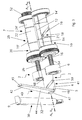
- Fig. 1 shows an isometric view of an embodiment of the vibration generator 1 according to the invention.
- the vibration exciter 1 comprises an exciter housing 3 with a housing head 5 which form a receiving space for excitation means 7, which allow the generation of a directed exciter oscillation.
- the vibration generator shown can be installed in a construction machine and in particular a vibration compressor.
- Fig. 2 shows the embodiment according to Fig. 1 , wherein the exciter housing 3 has been partially removed, so that now the exciter 7 can be seen clearly.
- the excitation means 7 are two imbalance shafts 10, 20, on which both movable imbalance masses 12, 22 and fixed imbalance masses 14, 24 are arranged.
- the movable imbalance masses 12, 22 are movable via an adjusting device 2, comprising an axial force element 40 relative to the fixed unbalanced masses 14, 24 and in particular rotatable about the respective imbalance shaft 10, 20, that during a rotation of the two unbalanced shafts 10, 20 Amplitude of the excitation oscillation changed.
- the vibration generator 1 has a rotational force element 30, which is designed here as a lifting cylinder 32 and is so eccentrically struck on the housing head 5 that it allows a rotation of the vibration exciter 1 about an axis A SE with a change in length, here coaxial with the main axis of extension of an actuating element 4 (see Fig. 3 ) runs.
- a rotational force element 30 which is designed here as a lifting cylinder 32 and is so eccentrically struck on the housing head 5 that it allows a rotation of the vibration exciter 1 about an axis A SE with a change in length, here coaxial with the main axis of extension of an actuating element 4 (see Fig. 3 ) runs.
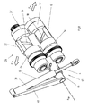
- Fig. 3 shows the presentation Fig. 2 now with completely removed exciter housing and in the interests of clarity slightly shifted force element 30th
- the two imbalance shafts 10, 20 which have the movable imbalance masses 12, 22 and the fixed imbalance masses 14, 24. When set in rotation, these imbalance masses cause the directed excitation oscillation.
- the drive of the two unbalanced shafts 10, 20 via a drive element and in particular drive gear 52, which is engageable with a motor (not shown) in operative connection.
- the two imbalance shafts 10, 20 are in operative connection with one another in such a way that an opposite rotational movement into the unbalanced shafts 10, 20 can be introduced via the drive gear wheel 52.
- the axial force element 40 is provided, which initiates an axial movement along an axis of symmetry A S , which runs between the two unbalanced shafts 10, 20, into two axial adjusting elements 16, 26.
- Axialstellelemente 16, 26 are with the movable imbalance masses 12, 22 in a helical groove-engaging engagement, so that upon axial movement of the Axialstellelemente 16, 26, a rotational movement of the movable imbalance masses 12, 22 relative to the fixed imbalance masses 14,24 results.
- the axial adjusting elements 16, 26 are connected via a yoke element 6 with the previously mentioned central control element 4, so that via this central control element 4 a synchronized axial movement of the two Axialstellelemente 16, 26 and thus a synchronized adjustment of the movable imbalance masses 12, 22 is possible ,
- the helical grooves 19 formed on the two unbalanced shafts 10, 20 are designed in opposite directions, as a result of which an opposing adjustment of the movable imbalance masses 12, 22 is achieved via the axial adjusting elements.
- the central control element 4 is designed such that a rotation of the vibration exciter 1 (see in particular Fig. 1 ) about the axis A SE of the central control element A SE is possible, so that not only an amplitude adjustment (by a movement of the movable unbalanced masses 10, 20) but also a vector adjustment (by a rotation of the excitation means 7 and des Vibration generator 1 about the axis A SE ) can take place.
- a rotational force element 30 with a lifting cylinder 32 is arranged on the vibration exciter 1, specifically eccentric to the axis A SE of the central actuating element 4, that upon extension or shortening of the lifting cylinder 32, a rotation of the vibration exciter 1 about this axis A SE results.
- the lifting cylinder 32 is struck with a mounting end 9 at a fixed point of the machine in which the vibration exciter is installed.
- the axial force element 40 is coupled, which is designed here as a passive axial force element 40 and is in direct operative connection with the rotational force element 30.
- the axial force element 40 has a coupling element 42 which can be arranged between the vibration exciter 1 and a further or the same external fixed point on the machine (not shown).
- the coupling element 42 is connected to the central actuating element 4 in a helical groove-engaging engagement 41 such that a rotational movement initiated by the rotational force element 30 on the vibration exciter 1 is converted about the axis A SE into an axial movement of the central actuating element 4 parallel to the axis A SE ,
- the central control element 4 is at least partially formed as a hollow shaft 38, wherein it has a helical groove 50 in its wall into which a driver 48 engages non-positively.
- a driver 48 engages non-positively.
- the interior of the hollow shaft 38 engages a complementarily formed coupling pin 46 a.
- this coupling pin 46 of the driver 48 is arranged, which is in operative connection with the helical groove 50.
- a coupling arm 44 is arranged, which is posted with its free end 45 at the fixed point of the machine (not shown). Due to the static coupling between the coupling element 42 or the coupling arm 44 and the fixed point, a rotation of the vibration exciter 1 about the axis A SE of the central control element 4 results in an axial displacement of the central control element 4 along the axis A SE . This means that a vector adjustment (causes the rotation about the axis A SE ) simultaneously also an amplitude adjustment.
- the result of the weiderum is that in the case of a vertically directed excitation oscillation, as is the case in the Fig.
- a maximum oscillation amplitude or a maximum excitation force acts, while at a substantially horizontally directed oscillation amplitude or excitation force, as for example in Fig. 8 acts, at the same time also reduces the vibration amplitude itself and so the loads on the vibration exciter 1 and the machine can be reduced.
- FIG. 4 and 5 show the embodiment as shown in Fig. 3 is shown in a partially sectioned view, wherein the representation of the lifting cylinder 32 has been omitted. Clear recognizable is the execution of the central control element 4 as a hollow shaft 38 and the spiral groove 50 disposed therein, which is in operative engagement with the coupling pin 46 and its driver 48.
- helical groove driver interventions 18, 28 in which also a helical groove 19 is on the movable imbalance mass 12, 22 with a driving pin 21 in operative engagement.
- the Fig. 6-8 show the course of the combined amplitude and vector adjustment.
- Fig. 6 the two unbalanced shafts 10, 20 are arranged substantially in a horizontal plane.
- the movable imbalance masses 12, 22 are moreover arranged relative to the fixed unbalanced masses 14, 24 such that a maximum oscillation amplitude or a maximum exciter force F V results in the vertical direction.
- the vibration exciter 1 can be rotated about the axis A SE so that the unbalanced shafts 10, 20 no longer run in a horizontal but in a vertical plane. This is in Fig. 8 shown.
- the lifting cylinder 32 is activated and changed in length and in particular extended, so that it is about his engagement with the eccentric pin 34 on the housing head 5 (see Fig. 2 ) the vibration exciter 1 is rotated about the axis A SE .
- an amplitude adjustment takes place via the functional coupling between the rotational force element 30 and the axial force element 40 in that the movable imbalance masses 12, 22 are rotated relative to the fixed imbalance masses 14, 24.
- the result is a substantially horizontally directed, reduced oscillation amplitude or excitation force F H , which in this embodiment corresponds to a fraction of the vertically acting exciter force F V.
- Fig. 9 shows a second embodiment of the vibration exciter according to the invention, which in its basic structure essentially the vibration generator described above according to the Fig. 1 - 8 equivalent.
- two imbalance shafts 10, 20 are arranged coaxially with one another and symmetrically about an axis of symmetry A S and are coupled to one another in such a way that they rotate in opposite directions to one another.
- the adjustment of the unbalanced shafts 10, 20 arranged movable imbalance masses 12, 22 also takes place again via two Axialstellelemente 16, 26, which are coupled together via a yoke member 6 and are centrally operated with a central control element 4.
- the central actuating element 4 two force elements formed separately from one another are arranged on the central actuating element 4, namely an axial force element 40 and a rotational force element 30, each of which can be activated individually for the amplitude adjustment or the vector adjustment.
- the axial force element 40 allows, for example by means of an integrated hydraulic cylinder (not shown), the axial displacement of the central control element 4 along its main extension axis A SE , which is coaxial to the axis of symmetry A S.
- the rotational force element 30 allows the rotation of the central control element 4 and thus the rotation of the excitation means 7 and the vibration exciter. 1
- both force elements 30, 40 are arranged on one side of the vibration exciter 1. This leads to a very compact and inexpensive vibration exciter.
- the coupling between amplitude adjustment and vector adjustment can also be produced in this embodiment, whereby this control device is designed in particular such that it controls the amplitude adjustment or the axial force element 40 simultaneously or as a function of the vector adjustment or rotational force element 30 , or the other way around.
Landscapes
- Engineering & Computer Science (AREA)
- Mechanical Engineering (AREA)
- Apparatuses For Generation Of Mechanical Vibrations (AREA)
- Road Paving Machines (AREA)
- Vibration Prevention Devices (AREA)
Applications Claiming Priority (1)
| Application Number | Priority Date | Filing Date | Title |
|---|---|---|---|
| DE102011112316.8A DE102011112316B4 (de) | 2011-09-02 | 2011-09-02 | Schwingungserreger zur Erzeugung einer gerichteten Erregerschwingung |
Publications (2)
| Publication Number | Publication Date |
|---|---|
| EP2564943A2 true EP2564943A2 (fr) | 2013-03-06 |
| EP2564943A3 EP2564943A3 (fr) | 2017-04-26 |
Family
ID=46548182
Family Applications (1)
| Application Number | Title | Priority Date | Filing Date |
|---|---|---|---|
| EP12005082.8A Withdrawn EP2564943A3 (fr) | 2011-09-02 | 2012-07-09 | Générateur de vibrations pour produire une vibration de source ciblée |
Country Status (5)
| Country | Link |
|---|---|
| US (1) | US9192962B2 (fr) |
| EP (1) | EP2564943A3 (fr) |
| JP (1) | JP5963615B2 (fr) |
| CN (1) | CN102979081B (fr) |
| DE (1) | DE102011112316B4 (fr) |
Families Citing this family (8)
| Publication number | Priority date | Publication date | Assignee | Title |
|---|---|---|---|---|
| CN103720378A (zh) * | 2013-12-20 | 2014-04-16 | 吴江市俊成精密机械有限公司 | 一种油炸用滤网 |
| KR101618944B1 (ko) * | 2014-02-24 | 2016-05-10 | 곽준영 | 진폭제어 진동발생기 및 그 방법 |
| FR3057786B1 (fr) * | 2016-10-21 | 2018-12-07 | Hutchinson | Generateur d'efforts dynamiques a balourd et un actionneur comprenant un tel generateur. |
| US10366958B2 (en) * | 2017-12-28 | 2019-07-30 | Texas Instruments Incorporated | Wire bonding between isolation capacitors for multichip modules |
| GB2570351B (en) | 2018-01-23 | 2021-03-31 | Terex Gb Ltd | Vibration generating mechanism for a vibrating screen box |
| US11420197B2 (en) * | 2018-11-05 | 2022-08-23 | Hycor Biomedical, Llc | Apparatus and method for mixing fluid or media by vibrating a pipette using nonconcentric masses |
| US12084873B2 (en) | 2020-08-11 | 2024-09-10 | Milwaukee Electric Tool Corporation | Vibrating screed |
| US11529652B1 (en) * | 2021-06-10 | 2022-12-20 | Xin Xiang San Yuan Tang Machinery Co., Ltd. | Double vibration source square oscillating sieve |
Citations (3)
| Publication number | Priority date | Publication date | Assignee | Title |
|---|---|---|---|---|
| DE10038206A1 (de) | 2000-08-04 | 2002-02-21 | Wacker Werke Kg | Regelbarer Schwingungserreger |
| DE10057807A1 (de) | 2000-11-22 | 2002-06-06 | Wacker Werke Kg | Verstelleinrichtung für Funktionsparameter bei einem Unwucht-Schwingungserreger |
| DE10241200A1 (de) | 2002-09-05 | 2004-03-25 | Wacker Construction Equipment Ag | Schwingungserreger für Bodenverdichtungsgeräte |
Family Cites Families (30)
| Publication number | Priority date | Publication date | Assignee | Title |
|---|---|---|---|---|
| US2206386A (en) * | 1938-10-25 | 1940-07-02 | Rudolf K Bernhard | Testing apparatus |
| US2248182A (en) * | 1940-03-27 | 1941-07-08 | Edward W Mateer | Vibratory motion producing apparatus |
| US2309172A (en) * | 1940-04-03 | 1943-01-26 | Kanski Leon M De | Vibrating processing machine |
| US2258217A (en) * | 1940-04-11 | 1941-10-07 | Robins Conveying Belt Co | Gyratory apparatus |
| FR894514A (fr) * | 1942-05-01 | 1944-12-27 | Dispositif générateur de vibrations dirigées | |
| US2627849A (en) * | 1950-01-03 | 1953-02-10 | Goodwin A Carlson | Gasoline hammer |
| NL102228C (fr) * | 1957-11-23 | |||
| NL277215A (fr) * | 1961-04-14 | |||
| US3287983A (en) * | 1963-01-25 | 1966-11-29 | Gen Mills Inc | Variable force oscillator |
| DE1758226A1 (de) * | 1968-04-26 | 1971-01-14 | Losenhausen Maschb Ag | Unwuchtruettler |
| US3640508A (en) * | 1969-06-25 | 1972-02-08 | All American Tool & Mfg Co | Vibration force generator |
| US3832080A (en) * | 1972-06-28 | 1974-08-27 | Heinrich Machinery & Tool Mfg | Vibrator, especially a self propelled reversible tamper |
| DE2409417A1 (de) * | 1974-02-27 | 1975-09-04 | Wacker Werke Kg | Schwingungserreger mit zwei relativ zueinander in der phasenlage kontinuierlich verstellbaren unwuchten |
| US4034246A (en) * | 1974-12-26 | 1977-07-05 | Akinobu Nakashima | Variable vibrating motor |
| DE2736264A1 (de) * | 1977-08-11 | 1979-03-01 | Schlosser & Co Gmbh | Schwingungserreger, insbesondere fuer verdichtungsruettler |
| DE3033476C2 (de) * | 1980-09-05 | 1985-03-21 | Delmag-Maschinenfabrik Reinhold Dornfeld Gmbh + Co, 7300 Esslingen | Vibrationsgerät zur Materialverdichtung |
| SE434550B (sv) * | 1983-01-26 | 1984-07-30 | Dynapac Maskin Ab | Anordning for lagring av stora exenterkrafter |
| DE3806897A1 (de) * | 1988-03-03 | 1989-09-14 | Wacker Werke Kg | Schwingungserreger |
| US5177386A (en) * | 1990-08-30 | 1993-01-05 | Kencho Kobe Co., Ltd. | Vibration generator adjustable during operation |
| CN2099742U (zh) * | 1991-08-15 | 1992-03-25 | 唐山冶金矿山机械厂第三联营厂 | 一种振动给料机 |
| DE4129182A1 (de) * | 1991-09-03 | 1993-03-04 | Bomag Gmbh | Verdichtungsgeraet |
| US6321610B1 (en) * | 1999-08-08 | 2001-11-27 | Kabushiki Kaisha Kei | Vibration apparatus for a variable amplitude type vibration table |
| DE10053446B4 (de) * | 2000-10-27 | 2006-03-02 | Wacker Construction Equipment Ag | Lenkbare Vibrationsplatte und fahrbares Vibrationsplattensystem |
| DE10147957B4 (de) * | 2001-09-28 | 2006-11-02 | Wacker Construction Equipment Ag | Schwingungserreger für eine Bodenverdichtungsvorrichtung |
| DE10306791A1 (de) * | 2003-02-18 | 2004-08-26 | Bomag Gmbh | Schwingungserregervorrichtung |
| SE525020C2 (sv) * | 2003-03-21 | 2004-11-09 | Metso Dynapac Ab | Ställdon för reglering av en vältvals excenteraxels excentermoment |
| DE102007018353A1 (de) * | 2007-04-18 | 2008-10-30 | Wacker Construction Equipment Ag | Schwingungserreger für Bodenverdichtungsvorrichtungen |
| DE102007049435A1 (de) * | 2007-10-16 | 2009-04-30 | Thyssenkrupp Gft Tiefbautechnik Gmbh | Vorrichtung zur Erzeugung von Schwingungen |
| DE102008050576A1 (de) * | 2008-10-06 | 2010-04-08 | Bomag Gmbh | Vorrichtung zur Erzeugung einer Kreisschwingung oder einer gerichteten Schwingung mit stufenlos verstellbarer Schwingungsamplitude bzw. Erregerkraft |
| DE102010010037B4 (de) * | 2010-03-03 | 2019-10-31 | Bomag Gmbh | Stufenlos verstellbarer Schwingungserreger |
-
2011
- 2011-09-02 DE DE102011112316.8A patent/DE102011112316B4/de active Active
-
2012
- 2012-07-09 EP EP12005082.8A patent/EP2564943A3/fr not_active Withdrawn
- 2012-08-03 US US13/565,899 patent/US9192962B2/en active Active
- 2012-08-21 CN CN201210298594.XA patent/CN102979081B/zh not_active Expired - Fee Related
- 2012-08-30 JP JP2012190221A patent/JP5963615B2/ja not_active Expired - Fee Related
Patent Citations (3)
| Publication number | Priority date | Publication date | Assignee | Title |
|---|---|---|---|---|
| DE10038206A1 (de) | 2000-08-04 | 2002-02-21 | Wacker Werke Kg | Regelbarer Schwingungserreger |
| DE10057807A1 (de) | 2000-11-22 | 2002-06-06 | Wacker Werke Kg | Verstelleinrichtung für Funktionsparameter bei einem Unwucht-Schwingungserreger |
| DE10241200A1 (de) | 2002-09-05 | 2004-03-25 | Wacker Construction Equipment Ag | Schwingungserreger für Bodenverdichtungsgeräte |
Also Published As
| Publication number | Publication date |
|---|---|
| DE102011112316B4 (de) | 2020-06-10 |
| US9192962B2 (en) | 2015-11-24 |
| CN102979081A (zh) | 2013-03-20 |
| CN102979081B (zh) | 2015-11-25 |
| JP2013053513A (ja) | 2013-03-21 |
| US20130055835A1 (en) | 2013-03-07 |
| JP5963615B2 (ja) | 2016-08-03 |
| DE102011112316A1 (de) | 2013-03-07 |
| EP2564943A3 (fr) | 2017-04-26 |
Similar Documents
| Publication | Publication Date | Title |
|---|---|---|
| EP2564943A2 (fr) | Générateur de vibrations pour produire une vibration de source ciblée | |
| EP2599918B1 (fr) | Procédé et dispositif de réglage des amplitudes d'une barre de dame d'une finisseuse de route | |
| EP2172279B1 (fr) | Dispositif de production d'une oscillation circulaire ou d'une oscillation orientée dotée d'une amplitude d'oscillation ou d'une force d'excitation réglable en continu | |
| DE3413091C2 (fr) | ||
| EP2390416B1 (fr) | Dispositif de vibration pour appareil de compactage du sol et appareil de compactage du sol | |
| DE2633578C2 (de) | Vibrator mit verstellbarer Schwungmasse | |
| EP3450631B1 (fr) | Vibreur en profondeur avec une masse non équilibrée réglable | |
| EP1305121B1 (fr) | Vibreur reglable | |
| EP3243573B1 (fr) | Dispositif de production de vibrations | |
| DE10147957B4 (de) | Schwingungserreger für eine Bodenverdichtungsvorrichtung | |
| EP2938442B1 (fr) | Generateur de vibrations pour dispositifs de compactage du sol dirigeables | |
| EP2242590B1 (fr) | Excitateur à balourds comprenant un ou plusieurs balourds rotatifs | |
| EP2732100A1 (fr) | Excitateur à balourd pour compacteur de sol | |
| EP2808161B1 (fr) | Dispositif de compacteur à rouleaux pour le compactage de déchets et de matières recyclables | |
| DE102014019139A1 (de) | Tiefenrüttler mit veränderbarer Unwucht | |
| EP1534439B1 (fr) | Oscillateur destine a des engins de compactage du sol | |
| WO2011160147A2 (fr) | Dispositif de forge | |
| EP2938441B1 (fr) | Générateur de vibrations pour dispositifs de compactage du sol | |
| EP3165290B1 (fr) | Dispositif de production de vibrations et procede d'introduction de profile dans un sol | |
| DE102013021494A1 (de) | Schwingungserreger für eine mobile Vibrationsplatte und Vibrationsplatte mit einem derartigen Schwingungserreger | |
| EP3472493B1 (fr) | Dispositif de transmission de force | |
| WO2017016794A1 (fr) | Dispositif de réglage d'une colonne de direction d'un véhicule à moteur et système de direction | |
| DE102004028715B3 (de) | Schwingungserreger und Verstellvorrichtung dafür | |
| DE102008006748B4 (de) | Unsymmetrischer Schwingungserreger für eine Vibrationsplatte | |
| DE102008017058B4 (de) | Seitensteuerung für eine Vibrationsplatte |
Legal Events
| Date | Code | Title | Description |
|---|---|---|---|
| PUAI | Public reference made under article 153(3) epc to a published international application that has entered the european phase |
Free format text: ORIGINAL CODE: 0009012 |
|
| AK | Designated contracting states |
Kind code of ref document: A2 Designated state(s): AL AT BE BG CH CY CZ DE DK EE ES FI FR GB GR HR HU IE IS IT LI LT LU LV MC MK MT NL NO PL PT RO RS SE SI SK SM TR |
|
| AX | Request for extension of the european patent |
Extension state: BA ME |
|
| PUAL | Search report despatched |
Free format text: ORIGINAL CODE: 0009013 |
|
| AK | Designated contracting states |
Kind code of ref document: A3 Designated state(s): AL AT BE BG CH CY CZ DE DK EE ES FI FR GB GR HR HU IE IS IT LI LT LU LV MC MK MT NL NO PL PT RO RS SE SI SK SM TR |
|
| AX | Request for extension of the european patent |
Extension state: BA ME |
|
| RIC1 | Information provided on ipc code assigned before grant |
Ipc: B06B 1/16 20060101AFI20170317BHEP |
|
| STAA | Information on the status of an ep patent application or granted ep patent |
Free format text: STATUS: REQUEST FOR EXAMINATION WAS MADE |
|
| 17P | Request for examination filed |
Effective date: 20171017 |
|
| RBV | Designated contracting states (corrected) |
Designated state(s): AL AT BE BG CH CY CZ DE DK EE ES FI FR GB GR HR HU IE IS IT LI LT LU LV MC MK MT NL NO PL PT RO RS SE SI SK SM TR |
|
| STAA | Information on the status of an ep patent application or granted ep patent |
Free format text: STATUS: EXAMINATION IS IN PROGRESS |
|
| 17Q | First examination report despatched |
Effective date: 20191004 |
|
| STAA | Information on the status of an ep patent application or granted ep patent |
Free format text: STATUS: EXAMINATION IS IN PROGRESS |
|
| STAA | Information on the status of an ep patent application or granted ep patent |
Free format text: STATUS: THE APPLICATION IS DEEMED TO BE WITHDRAWN |
|
| 18D | Application deemed to be withdrawn |
Effective date: 20210202 |