EP2022176B1 - Verfahren zur verringerung des stromverbrauchs für eine ablösbare karte und mobilkommunikationsendgerät dafür - Google Patents
Verfahren zur verringerung des stromverbrauchs für eine ablösbare karte und mobilkommunikationsendgerät dafür Download PDFInfo
- Publication number
- EP2022176B1 EP2022176B1 EP07746607.6A EP07746607A EP2022176B1 EP 2022176 B1 EP2022176 B1 EP 2022176B1 EP 07746607 A EP07746607 A EP 07746607A EP 2022176 B1 EP2022176 B1 EP 2022176B1
- Authority
- EP
- European Patent Office
- Prior art keywords
- card
- cards
- mobile communication
- communication terminal
- low voltage
- Prior art date
- Legal status (The legal status is an assumption and is not a legal conclusion. Google has not performed a legal analysis and makes no representation as to the accuracy of the status listed.)
- Not-in-force
Links
- 238000010295 mobile communication Methods 0.000 title claims description 84
- 238000000034 method Methods 0.000 title claims description 26
- 238000010586 diagram Methods 0.000 description 4
- 230000009977 dual effect Effects 0.000 description 3
- 230000006870 function Effects 0.000 description 3
- 238000004891 communication Methods 0.000 description 2
- 238000012986 modification Methods 0.000 description 2
- 230000004048 modification Effects 0.000 description 2
- 230000009849 deactivation Effects 0.000 description 1
- 239000004973 liquid crystal related substance Substances 0.000 description 1
- 238000005457 optimization Methods 0.000 description 1
- 239000004065 semiconductor Substances 0.000 description 1
- 238000004904 shortening Methods 0.000 description 1
Images


Classifications
-
- H—ELECTRICITY
- H04—ELECTRIC COMMUNICATION TECHNIQUE
- H04B—TRANSMISSION
- H04B1/00—Details of transmission systems, not covered by a single one of groups H04B3/00 - H04B13/00; Details of transmission systems not characterised by the medium used for transmission
- H04B1/06—Receivers
- H04B1/16—Circuits
- H04B1/1607—Supply circuits
- H04B1/1615—Switching on; Switching off, e.g. remotely
-
- H—ELECTRICITY
- H04—ELECTRIC COMMUNICATION TECHNIQUE
- H04B—TRANSMISSION
- H04B1/00—Details of transmission systems, not covered by a single one of groups H04B3/00 - H04B13/00; Details of transmission systems not characterised by the medium used for transmission
- H04B1/38—Transceivers, i.e. devices in which transmitter and receiver form a structural unit and in which at least one part is used for functions of transmitting and receiving
- H04B1/3816—Mechanical arrangements for accommodating identification devices, e.g. cards or chips; with connectors for programming identification devices
-
- H—ELECTRICITY
- H04—ELECTRIC COMMUNICATION TECHNIQUE
- H04W—WIRELESS COMMUNICATION NETWORKS
- H04W52/00—Power management, e.g. Transmission Power Control [TPC] or power classes
- H04W52/02—Power saving arrangements
- H04W52/0209—Power saving arrangements in terminal devices
- H04W52/0261—Power saving arrangements in terminal devices managing power supply demand, e.g. depending on battery level
-
- H—ELECTRICITY
- H04—ELECTRIC COMMUNICATION TECHNIQUE
- H04M—TELEPHONIC COMMUNICATION
- H04M2250/00—Details of telephonic subscriber devices
- H04M2250/14—Details of telephonic subscriber devices including a card reading device
-
- H—ELECTRICITY
- H04—ELECTRIC COMMUNICATION TECHNIQUE
- H04W—WIRELESS COMMUNICATION NETWORKS
- H04W8/00—Network data management
- H04W8/18—Processing of user or subscriber data, e.g. subscribed services, user preferences or user profiles; Transfer of user or subscriber data
- H04W8/183—Processing at user equipment or user record carrier
-
- Y—GENERAL TAGGING OF NEW TECHNOLOGICAL DEVELOPMENTS; GENERAL TAGGING OF CROSS-SECTIONAL TECHNOLOGIES SPANNING OVER SEVERAL SECTIONS OF THE IPC; TECHNICAL SUBJECTS COVERED BY FORMER USPC CROSS-REFERENCE ART COLLECTIONS [XRACs] AND DIGESTS
- Y02—TECHNOLOGIES OR APPLICATIONS FOR MITIGATION OR ADAPTATION AGAINST CLIMATE CHANGE
- Y02D—CLIMATE CHANGE MITIGATION TECHNOLOGIES IN INFORMATION AND COMMUNICATION TECHNOLOGIES [ICT], I.E. INFORMATION AND COMMUNICATION TECHNOLOGIES AIMING AT THE REDUCTION OF THEIR OWN ENERGY USE
- Y02D30/00—Reducing energy consumption in communication networks
- Y02D30/70—Reducing energy consumption in communication networks in wireless communication networks
Definitions
- the present disclosure relates to a method for supplying power to a detachable card, and more particularly, to a method for reducing power consumption of a detachable card.
- a mobile communication terminal is provided with a first detachable card called as a subscriber identity module (SIM) or a user identity module (UIM) therein.
- SIM subscriber identity module
- UIM user identity module
- the SIM card is a detachable card for a GSM-based mobile communication terminal, and consists of a microprocessor and a memory chip.
- the SIM card is largely classified into an IC card type and a plug-in type.
- the SIM card has all information therein necessary to operate the mobile communication terminal, and has encrypted data therein including not only a user's private information but also relevant information such as a phone number and a network number.
- the UIM card is a detachable smart card for a CDMA-based mobile communication terminal, and performs the same function as the SIM card. That is, the UIM card includes information regarding a network set, a priority, a user set, a phone number, and an access security.
- the mobile communication terminal may be provided with a second detachable card for storing a user's data, i.e., a sound file, a moving image file, a data file, etc.
- a user's data i.e., a sound file, a moving image file, a data file, etc.
- the first detachable card and the second detachable card are operated with the same driving voltage. That is, despite that the first detachable card can be operated with a voltage lower than that of the second detachable card, the first and second detachable cards are operated with the same high voltage. Accordingly, a power consumption of a battery for the mobile communication terminal is increased, thereby shortening a usage time.
- EP 1 239 400 discloses a dual smartcard controller configured to supply independent power to smartcard readers. Voltages are supplied to two smart cards independently based on their voltage requirements.
- EP 1 630 727 discloses a multi-interface card configured to manage power requirements of a terminal configured to host a SIM card and a memory card.
- WO 2006/048997 discloses a mobile terminal configured to supply power to an SD card only when a music application is launched.
- EP 0 562 295 discloses a pay TV decoder configured to operate different smart cards. Each smart card is suppled with individual voltages.
- an object of the present disclosure is to provide a method and a mobile communication terminal for supplying, if possible, a low voltage to at least one of a first detachable card and a second detachable card.
- another object of the present disclosure is to provide a method and a mobile communication terminal for supplying different voltages to each of the first and second detachable cards so that at least one of the first and second detachable cards may be provided with a low voltage though the other of them may be provided with a high voltage.
- a method for reducing power consumption of a detachable card for a mobile communication terminal comprises the steps of claim 1.
- a method for reducing power consumption of a detachable card for a mobile communication terminal may comprise the steps of: receiving a request for operating a first detachable card; operating the first detachable card with a low voltage, if the first detachable card can be operated with a low voltage; receiving a request for operating a second detachable card; operating the first and second detachable cards with a high voltage, when the second detachable card can not be operated with a low voltage.
- a method for reducing power consumption of a detachable card for a mobile communication terminal may comprise the steps of: operating first and second detachable cards with a high voltage; receiving a request for stopping the operation of one of the first and second detachable cards; operating another card with a low voltage if the another card can be operated with a low voltage.
- a mobile communication terminal comprises the features of claim 7.
- a mobile terminal may comprise: a first detachable card receiving unit for receiving a first detachable card; a second detachable card receiving unit for receiving a second detachable card; a power supply unit for supplying power to the first and second detachable cards each mountable at the first and second detachable card receiving units; and a controller for controlling the power supply unit so that voltage may be differently supplied, according to whether the first detachable card or the second detachable card is operated or not, to the first and second detachable cards.
- a first detachable card used in the present disclosure may be a subscriber identity module (SIM), a user identity module (UIM), a universal SIM (USIM), or a universal IC card (UICC).
- SIM subscriber identity module
- UIM user identity module
- USIM universal SIM
- UICC universal IC card
- the USIM is an extension module from the SIM and the UIM, and is mainly used in the 3 rd generation mobile communication, WCDMA mobile communication.
- the UICC is an extension module from the SIM or the UIM, and may be applied to a financial industry, a medical industry, etc.
- the first detachable card e.g., the UICC could be operated, according to various situations, with any one of voltages of the various types as followed.
- the first detachable card i.e., the UICC can be operated with any one of about 5V of a class A (not being currently used due to a very high voltage), about 3V of a class B, and about 1.8V of a class C Also, the first detachable card, i.e., the UICC may be operated with about 1V or less of a class D.
- the second detachable card may be a flash memory, more concretely, a multimedia card (MMC), further more particularly, at least one of an SD/MMC, an Mini-SD, or a Micro-SD (T-flash).
- MMC multimedia card
- the second detachable card serves to store a user's data including a multimedia file such as a sound file and a moving image file in a mobile communication terminal.
- the second detachable card may be operated with approximately 5V in a computer, and may be operated with approximately 3V in a mobile communication terminal.
- the enhanced second detachable card may be operated with two or more voltages according to each condition. That is, the enhanced second detachable card may be operated with 2.7-3.6V at a situation requiring a high voltage, and may be operated with 1.65-1.95V at a situation requiring a low voltage.
- the second detachable card operated with two voltages according to each circumstance is called as a dual voltage multimedia card (MMC).
- MMC dual voltage multimedia card
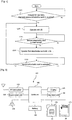
- FIG. 1 is a flowchart showing a method for reducing power consumption of a detachable card for a mobile communication terminal according to a first embodiment of the present disclosure.
- a power consumption of a battery is reduced by supplying a low voltage, if possible.
- the first detachable card is a UICC.
- the first detachable card is firstly operated than the second detachable card.
- the first detachable card can be operated with a low voltage, i.e., approximately 1.8V of the class C and the second detachable card can be operated with a high voltage, i.e., about 3V.
- a mobile communication terminal determines (or, checks) whether the first detachable card can be operated with a low voltage. When it is determined that the first detachable card can be operated with a low voltage, the mobile communication terminal operates the first detachable card with a low voltage (approximately 1.8V) (S 112).
- the request for operating the first detachable card may represent that the first detachable card is mounted at the mobile communication terminal.
- the request may represent that the mobile communication terminal establishes a session with the first detachable card after the first detachable card is mounted at the mobile communication terminal. That is, the request may represent that the mobile communication terminal accesses to (or, uses) the first detachable card.
- the mobile communication terminal determines (or, checks) whether the second detachable card can be operated with a low voltage.
- the mobile communication terminal operates the first and second detachable cards with a high voltage (i.e., about 3V) (S114).
- the request for operating the second detachable card indicates that the second detachable card is mounted at the mobile communication terminal, or the mobile communication terminal establishes a session with the second detachable card.
- the mobile communication terminal is returned to S112 for operating the first detachable card with a low voltage (1.8V).
- the request for stopping the operation of the second detachable card may represent that the second detachable card is separated from the mobile communication terminal, or is not used even if it is not separated from the mobile communication terminal.
- FIG. 2 is a flowchart showing a method for reducing power consumption of a detachable card for a mobile communication terminal according to another aspect of the first embodiment of the present disclosure.
- FIG. 2 in the same manner as FIG. 1 , power consumption of a battery is reduced by supplying a low voltage, if it is possible.
- FIG. 2 is different from FIG. 1 in that the second detachable card is firstly operated than the first detachable card.
- the mobile communication terminal determines whether or not the second detachable card can be operated with a low voltage. When it is determined that the second detachable card can not be operated with a low voltage, the mobile communication terminal operates the second detachable card with a high voltage (3V) (S122).
- the mobile communication terminal operates the first and second detachable cards with a high voltage (approximately 3V) (S124).
- a high voltage approximately 3V
- the second detachable card can not be operated with a low voltage
- the first and second detachable cards are operated with a high voltage (approximately 3V).
- the mobile communication terminal determines whether or not the first detachable card can be operated with a low voltage. When it is determined that the first detachable card can be operated with a low voltage, the mobile communication terminal operates the first detachable card with a low voltage (1.8V) (S126).
- the mobile communication terminal is returned to S124 for operating the first and second detachable cards with a high voltage (3V).
- FIG. 3 is a flowchart showing a method for reducing power consumption of a detachable card for a mobile communication terminal according to still another aspect of the first embodiment of the present disclosure.
- the second detachable card is firstly operated than the first detachable card.
- the second detachable card is a dual voltage MMC and is operated with a low voltage (1.65-1.95V) which is a low voltage between two or more voltages.
- the first detachable card is a UICC and is operated with a high voltage (approximately 3V) in the class B.
- the mobile communication terminal determines whether or not the second detachable card can be operated with a low voltage. When it is determined that the second detachable card can be operated with a low voltage, the mobile communication terminal operates the second detachable card with a low voltage (approximately 1.65-1.95V, preferably 1.8V) (S132).
- a low voltage approximately 1.65-1.95V, preferably 1.8V
- the mobile communication terminal determines whether or not the first detachable card can be operated with a low voltage. When it is determines that the first detachable card can not be operated with a low voltage, the mobile communication terminal operates the first and second detachable cards with a high voltage (3V) (S134).
- the mobile communication terminal is returned to S132 for operating the second detachable card with a low voltage.
- power consumption of a battery can be reduced by supplying a low voltage, if possible.
- FIG. 4 is a flowchart showing a method for reducing power consumption of a detachable card for a mobile communication terminal according to a second embodiment of the present disclosure.
- the deactivation may represent that the mobile communication terminal does not access to (use) one of the first and second detachable cards (i.e. temporarily deactivates a session with the card).
- the mobile communication terminal determines whether or not the first and the second detachable card can be operated with a low voltage. When it is determined that the first and the second detachable card can not be operated with a low voltage, the mobile communication terminal operates the first and second detachable cards with a high voltage (3V) (S202).
- the mobile communication terminal determines whether or not the first detachable card can be operated with a low voltage. When it is determined that the first detachable card can be operated with a low voltage, the mobile communication terminal operates the first detachable card with a low voltage (approximately 1.8V). Whether or not the second detachable card is temporarily deactivated may be determined by a timer. That is, if the second detachable card for the mobile communication terminal is determined not to have been used after lapse of a predetermined time set by the timer, it is determined that the second detachable card is deactivated.
- the predetermined time set by the timer may be optimized so as to minimize power consumption of the battery and to minimize the number of times that a voltage is changed. The optimization may be easily implemented by those skilled in the art, and thus is not numerically represented in the present disclosure.
- the mobile communication terminal is returned to S202 for operating the first and second detachable cards with a high voltage (3V).
- the second embodiment when one of the first and second detachable cards is temporarily deactivated, if another can be operated with a low voltage, a low voltage is supplied to the another card. Accordingly, power consumption of the battery is minimized.
- the method of the present disclosure may be implemented in a software manner, in a hardware manner, or in a combination manner therebetween.
- the method of the present disclosure may be implemented with a storage medium (e.g., an inner memory of a mobile communication terminal, a flash memory, a hard disc, etc.), or may be implemented by codes or commands inside a software program that can be executed by a processor (e.g, a microprocessor inside a mobile communication terminal).
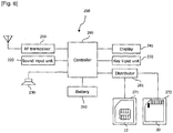
- FIG. 5 is a block diagram showing a mobile communication terminal according to the present disclosure.
- the mobile communication terminal 100 may comprise an RF transceiver 110, a sound input unit 120, a sound output unit 130, a display 140, a key input unit 150, a battery (power supply unit) 160, a first detachable card receiving unit 171 for receiving a first detachable card 10, a second detachable card receiving unit 172 for receiving a second detachable card 20, and a controller 180.
- the first detachable card 10 and the second detachable card 20 are the same cards as the aforementioned cards.
- the RF transceiver 110 may consist of electronic components for transceiving an electric wave.
- the RF transceiver 110 may consist of electronic components for supporting CDMA, GSM, GPRS, TDMA, IMT-2000, WCDMA, HSDPA, IEEE 802. 11, IEEE802. 16-based communication, etc.
- the RF transceiver 110 is electrically connected to the controller 180, and performs a communication under control of the controller 180.
- the sound input unit 120 receives a user's voice, and may be implemented as a microphone.
- the sound input unit 120 is controlled by the controller 180.
- the sound output unit 130 outputs another party's voice during a calling, or outputs each sound generated from the mobile communication terminal 100 (i.e., music, moving image, game, etc.).
- the sound output unit 130 is electrically connected to the controller 180 thus to be controlled.
- the display 140 may be implemented as a liquid crystal display (LCD) or an organic light emitting diode (OLED).
- the display 140 is electrically connected to the controller 180 thus to be controlled, and displays a screen according to each function of the mobile communication terminal 100.
- the key input unit 150 for receiving a signal inputted by a user is connected to the controller 180, and transmits the received signal to the controller 180.
- the battery 160 supplies a power to the RF transceiver 110, the sound input unit 120, the sound output unit 130, the display 140, the key input unit 150, the first detachable card 10, the second detachable card 20, and the controller 180.
- the controller 180 consists of a plurality of semiconductor devices, and is electrically connected to the RF transceiver 110, the sound input unit 120, the sound output unit 130, the display 140, the key input unit 150, the battery 160, the first detachable card receiving unit 10, and the second detachable card receiving unit 20.
- the controller 180 differently supplies voltage according to whether both of the first and the second detachable card 10 and 20 are operated, or any one of them is operated, more concretely, whether both the first and second detachable card 10 and 20 are mounted in each of the first and second detachable card receiving unit 171 and 172, or whether the mobile communication terminal 100 establishes sessions with both of them being mounted or one session with any one of them being mounted, thereby reducing power consumption of the battery 160.
- the controller 180 supplies a low voltage to the other card. Accordingly, power consumption of the battery 160 is reduced.
- the controller 180 may operate a timer provided therein so as to determine whether or not one of the first and second detachable cards is deactivated. That is, the controller 180 can monitor whether one of the first and second detachable cards has not been used after lapse of a predetermined time.
- FIG. 6 is a block diagram showing a mobile communication terminal according to another aspect of the present disclosure.
- a mobile communication terminal 200 supplies different voltages to first and second detachable cards 10 and 20 through a voltage distributor.
- the mobile communication terminal 200 may comprise an RF transceiver 210, a sound input unit 220, a sound output unit 230, a display 240, a key input unit 250, a battery (power supply unit) 260, a first detachable card receiving unit 271 for receiving the first detachable card 10, a second detachable card receiving unit 272 for receiving the second detachable card 20, a controller 280, and a voltage distributor 281.
- the first detachable card 10 and the second detachable card 20 are the same cards as the aforementioned cards. Explanation for components having the same function as those of FIG. 5 will be omitted.
- the voltage distributor 281 may receive a low voltage (1.8V) from the battery 260. Then, the voltage distributor 281 may provide the low voltage (1.8V) to the first detachable card 10, and a high voltage (3V which is obtained by boosting the 1.8V) to the second detachable card 20 according to a control signal from the controller 280.
- the voltage distributor 281 may receive a high voltage (3V) from the battery 260. Then, the voltage distributor 281 may provide a low voltage (1.8V which is obtained by reducing the 3V) to the first detachable card 10, and a high voltage (3V) to the second detachable card 20 according to a control signal from the controller 280.
- the voltage distributor 281 may not provide a voltage to a deactivated card according to a control signal from the controller 280.
- the controller 280 provides a control signal for boosting into 3V or reducing into 1.8V to the voltage distributor 281 according to an operation or non-operation state of the first detachable card or the second detachable card (i.e., according to whether the first detachable card 10 is mounted in the first detachable card receiving unit 271, whether the second detachable card 20 is mounted in the second detachable card receiving unit 272, or whether the mobile communication terminal 100 establishes sessions with them being mounted).
- the controller 280 may provide the voltage distributor 281 with a control signal for providing no voltage to a deactivated card.
- different voltages are supplied to the first and second detachable cards according to an operation or non-operation state of the first detachable card or the second detachable card, thereby reducing power consumption of the battery.
- first and second detachable cards when one of the first and second detachable cards is temporarily deactivated, if the other of them can be operated with a low voltage, a low voltage is supplied to the other card. Accordingly, power consumption of the battery is minimized.
Landscapes
- Engineering & Computer Science (AREA)
- Computer Networks & Wireless Communication (AREA)
- Signal Processing (AREA)
- Mobile Radio Communication Systems (AREA)
- Telephone Function (AREA)
Claims (10)
- Verfahren zum Reduzieren des Energieverbrauchs einer herausnehmbaren Karte für ein mobiles Kommunikationsendgerät (100), das ausgelegt ist, mit einer ersten und einer zweiten herausnehmbaren Karte (10, 20) zu arbeiten, wobei das Verfahren umfasst:Empfangen einer Anforderung zum Betreiben entweder der ersten oder der zweiten Karte;Ermitteln, ob die eine der ersten und der zweiten Karte, deren Betrieb angefordert wurde, mit einer niedrigen Spannung betrieben werden kann;
falls die eine der ersten und der zweiten Karte, deren Betrieb angefordert wurde, mit einer niedrigen Spannung betrieben werden kann, Betreiben der einen der ersten und der zweiten Karte mit einer niedrigen Spannung,Empfangen einer Anforderung zum Betreiben der anderen der ersten und der zweiten Karte;falls die andere der ersten und der zweiten Karte nicht mit einer niedrigen Spannung betrieben werden kann, Betreiben der ersten und der zweiten Karte mit einer hohen Spannung;falls die andere der ersten und der zweiten Karte mit einer niedrigen Spannung betrieben werden kann, Betreiben der ersten und der zweiten Karte mit einer niedrigen Spannung. - Verfahren nach Anspruch 1, ferner umfassend:eines von:Empfangen einer Anforderung zum Beenden des Betriebs entweder der ersten oder der zweiten Karte; undErmitteln, dass entweder die erste oder die zweite Karte nicht aktiviert ist, durch Prüfen, ob die eine der ersten oder der zweiten Karte für eine vorbestimmte Zeitspanne nicht verwendet wurde;Ermitteln, ob die andere der ersten und der zweiten Karte mit der niedrigen Spannung betrieben werden kann; undBetreiben der anderen der ersten und der zweiten Karte mit der niedrigen Spannung, wenn ermittelt wird, dass die andere der ersten und der zweiten Karte mit der niedrigen Spannung betrieben werden kann.
- Verfahren nach Anspruch 2, wobei, wenn die deaktivierte Karte, die nicht mit einer niedrigen Spannung betrieben werden kann, wieder aktiviert wird, Betreiben der ersten und der zweiten Karte mit der hohen Spannung.
- Verfahren nach einem der Ansprüche 1 bis 3, wobei die Anforderung zum Betreiben der ersten Karte mindestens eines darstellt von:Erkennen, durch das Endgerät, dass die erste Karte im mobilen Kommunikationsendgerät montiert wurde;Versuchen, durch das Endgerät, eine Sitzung mit der ersten Karte einzurichten, nachdem die erste Karte im mobilen Kommunikationsendgerät montiert wurde; Versuchen, durch das Endgerät, auf die erste Karte zuzugreifen, nachdem die erste Karte im mobilen Kommunikationsendgerät montiert wurde; und
Versuchen, durch das Endgerät, die erste Karte zu verwenden, nachdem die erste Karte im mobilen Kommunikationsendgerät montiert wurde. - Verfahren nach einem der Ansprüche 1 bis 4, wobei die Anforderung zum Betreiben der zweiten Karte mindestens eines darstellt von:Erkennen, durch das mobile Kommunikationsendgerät, dass die zweite Karte im mobilen Kommunikationsendgerät montiert ist;Versuchen, durch das mobile Kommunikationsendgerät, eine Sitzung mit der zweiten Karte einzurichten, nachdem die zweite Karte im mobilen Kommunikationsendgerät montiert wurde;Versuchen, durch das mobile Kommunikationsendgerät, auf die zweite Karte zuzugreifen, nachdem die zweite Karte im mobilen Kommunikationsendgerät montiert wurde; undVersuchen, durch das mobile Kommunikationsendgerät, die zweite Karte zu verwenden, nachdem die zweite Karte im mobilen Kommunikationsendgerät montiert wurde.
- Verfahren nach einem der Ansprüche 1 bis 5, wobei die erste Karte entweder ein Teilnehmeridentitätsmodul (SIM), ein Benutzeridentitätsmodul (UIM), ein Universal-SIM (USIM) oder eine universale IC-Karte (UICC) ist und die zweite Karte eine Multimediakarte (MMC) ist.
- Mobiles Kommunikationsendgerät (100), umfassend:eine Aufnahmeeinheit (171) für eine erste Karte zum Aufnehmen einer ersten Karte (10);eine Aufnahmeeinheit (172) für eine zweite Karte zum Aufnehmen einer zweiten Karte (20);eine Energieversorgungseinheit (160) zum Versorgen der ersten und der zweiten Karte mit Energie, die jeweils in den Aufnahmeeinheiten für die erste und die zweite Karte montierbar sind; undeine Steuerung (180), die ausgelegt ist zum:Empfangen einer Anforderung zum Betreiben entweder der ersten oder der zweiten Karte;Ermitteln, ob die eine der ersten und der zweiten Karte, deren Betrieb angefordert wurde, mit einer niedrigen Spannung betrieben werden kann;falls die eine der ersten und der zweiten Karte, deren Betrieb angefordert wurde, mit einer niedrigen Spannung betrieben werden kann, Steuern der Energieversorgung, um die eine der ersten und der zweiten Karte mit einer niedrigen Spannung zu versorgen,Empfangen einer Anforderung zum Betreiben der anderen der ersten und der zweiten Karte;falls die andere der ersten und der zweiten Karte nicht mit einer niedrigen Spannung betrieben werden kann, Steuern der Energieversorgung, um die erste und die zweite Karte mit einer hohen Spannung zu versorgen;falls die andere der ersten und der zweiten Karte mit einer niedrigen Spannung betrieben werden kann, Steuern der Energieversorgung, um die erste und die zweite Karte mit einer niedrigen Spannung zu versorgen.
- Endgerät nach Anspruch 7, wobei die Steuerung (180) ferner ausgelegt ist:eines von:Empfangen einer Anforderung zum Beenden des Betriebs entweder der ersten oder der zweiten Karte. undErmitteln, dass entweder die erste oder die zweite Karte nicht aktiviert ist, durch Prüfen, ob die eine der ersten oder der zweiten Karte für eine vorbestimmte Zeitspanne nicht verwendet wurde, wie durch einen Zeitgeber ermittelt;
Ermitteln, ob die andere der ersten und der zweiten Karte mit der niedrigen Spannung betrieben werden kann; undSteuern der Energieversorgung, um die andere der ersten und der zweiten Karte mit der niedrigen Spannung zu versorgen, wenn ermittelt wird, dass die andere der ersten und der zweiten Karte mit der niedrigen Spannung betrieben werden kann. - Endgerät nach Anspruch 8, wobei, wenn die deaktivierte Karte, die nicht mit einer niedrigen Spannung betrieben werden kann, wieder aktiviert wird, Steuern der Energieversorgung, um die erste und die zweite Karte mit der hohen Spannung zu versorgen.
- Endgerät nach einem der Ansprüche 7 bis 9, wobei die erste Karte entweder ein Teilnehmeridentitätsmodul (SIM), ein Benutzeridentitätsmodul (UIM), ein Universal-SIM (USIM) oder eine universale IC-Karte (UICC) ist und die zweite Karte eine Multimediakarte (MMC) ist.
Applications Claiming Priority (2)
| Application Number | Priority Date | Filing Date | Title |
|---|---|---|---|
| US80306006P | 2006-05-24 | 2006-05-24 | |
| PCT/KR2007/002459 WO2007136210A1 (en) | 2006-05-24 | 2007-05-21 | Method for reducing power consumption for detachable card and mobile communication terminal thereof |
Publications (3)
| Publication Number | Publication Date |
|---|---|
| EP2022176A1 EP2022176A1 (de) | 2009-02-11 |
| EP2022176A4 EP2022176A4 (de) | 2014-12-31 |
| EP2022176B1 true EP2022176B1 (de) | 2018-10-24 |
Family
ID=38723505
Family Applications (1)
| Application Number | Title | Priority Date | Filing Date |
|---|---|---|---|
| EP07746607.6A Not-in-force EP2022176B1 (de) | 2006-05-24 | 2007-05-21 | Verfahren zur verringerung des stromverbrauchs für eine ablösbare karte und mobilkommunikationsendgerät dafür |
Country Status (4)
| Country | Link |
|---|---|
| US (1) | US8060142B2 (de) |
| EP (1) | EP2022176B1 (de) |
| CN (1) | CN101454987B (de) |
| WO (1) | WO2007136210A1 (de) |
Families Citing this family (5)
| Publication number | Priority date | Publication date | Assignee | Title |
|---|---|---|---|---|
| JP5411425B2 (ja) * | 2007-12-25 | 2014-02-12 | 任天堂株式会社 | ゲームプログラム、ゲーム装置、ゲームシステム、およびゲーム処理方法 |
| US8649820B2 (en) | 2011-11-07 | 2014-02-11 | Blackberry Limited | Universal integrated circuit card apparatus and related methods |
| USD703208S1 (en) * | 2012-04-13 | 2014-04-22 | Blackberry Limited | UICC apparatus |
| US8936199B2 (en) | 2012-04-13 | 2015-01-20 | Blackberry Limited | UICC apparatus and related methods |
| USD701864S1 (en) * | 2012-04-23 | 2014-04-01 | Blackberry Limited | UICC apparatus |
Family Cites Families (19)
| Publication number | Priority date | Publication date | Assignee | Title |
|---|---|---|---|---|
| JPH01266695A (ja) * | 1988-04-18 | 1989-10-24 | Mitsubishi Electric Corp | メモリカードの電源制御回路 |
| JPH0439718A (ja) * | 1990-06-05 | 1992-02-10 | Mitsubishi Electric Corp | メモリカード電源通電装置 |
| EP0562295B1 (de) * | 1992-03-04 | 1997-05-02 | THOMSON multimedia | Methode und Vorrichtung zur Kontrolle mehrerer Chipkarten |
| JP2735435B2 (ja) * | 1992-06-01 | 1998-04-02 | 三菱電機株式会社 | メモリカードのメモリ制御用回路 |
| US5469399A (en) * | 1993-03-16 | 1995-11-21 | Kabushiki Kaisha Toshiba | Semiconductor memory, memory card, and method of driving power supply for EEPROM |
| EP0709002B1 (de) * | 1993-07-16 | 1997-04-02 | Ericsson Inc. | Verfahren und gerat zum steuern des betriebes einer sender-/empfangeranordnung in einem funkkommunikationsystem |
| JPH08505747A (ja) * | 1993-08-31 | 1996-06-18 | エリクソン ジーイー モービル コミュニケーションズ インコーポレイテッド | セルラ移動機端末内でのメッセージ格納装置 |
| US5867795A (en) * | 1996-08-23 | 1999-02-02 | Motorola, Inc. | Portable electronic device with transceiver and visual image display |
| FR2756400B1 (fr) * | 1996-11-28 | 1999-12-03 | Bornes De Distribution Sofabod | Procede et dispositif d'autorisation et de controle par carte a memoire pour la distribution et le comptage de consommation d'au moins un fluide ou energie |
| JP3058115B2 (ja) * | 1997-03-24 | 2000-07-04 | 日本電気株式会社 | 移動体通信装置、移動体通信装置の電源供給装置および電源供給方法、および、移動体通信装置に接続可能なデータ端末接続カード装置 |
| JP3134802B2 (ja) * | 1997-03-24 | 2001-02-13 | 日本電気株式会社 | 移動体通信装置、移動体通信装置の電源供給装置および電源供給方法、および、移動体通信装置に接続可能なデータ端末接続モデムカード |
| FI107973B (fi) * | 1999-03-11 | 2001-10-31 | Nokia Mobile Phones Ltd | Menetelmä ja välineet lisäkorttien käyttämiseksi matkaviestimessä |
| JP4261802B2 (ja) * | 2000-04-28 | 2009-04-30 | 株式会社ルネサステクノロジ | Icカード |
| JP3576977B2 (ja) * | 2001-01-12 | 2004-10-13 | 株式会社東芝 | 携帯端末 |
| EP1239400A1 (de) * | 2001-03-09 | 2002-09-11 | Semiconductor Components Industries, LLC | Lesegerät für zwei Chipkarten |
| US7376444B2 (en) * | 2004-02-27 | 2008-05-20 | Jigatek Corporation | Method and apparatus for radio frequency identification |
| KR100579053B1 (ko) * | 2004-08-26 | 2006-05-12 | 삼성전자주식회사 | 스마트 카드와 메모리 카드간의 멀티 인터페이스 방법 및멀티 인터페이스 카드 |
| US7196958B2 (en) * | 2004-08-31 | 2007-03-27 | Micron Technology, Inc. | Power efficient memory and cards |
| CN101040240B (zh) * | 2004-11-04 | 2010-05-12 | 松下电器产业株式会社 | 便携式终端 |
-
2007
- 2007-05-21 EP EP07746607.6A patent/EP2022176B1/de not_active Not-in-force
- 2007-05-21 US US12/301,964 patent/US8060142B2/en not_active Expired - Fee Related
- 2007-05-21 CN CN2007800190076A patent/CN101454987B/zh not_active Expired - Fee Related
- 2007-05-21 WO PCT/KR2007/002459 patent/WO2007136210A1/en not_active Ceased
Also Published As
| Publication number | Publication date |
|---|---|
| EP2022176A1 (de) | 2009-02-11 |
| EP2022176A4 (de) | 2014-12-31 |
| US8060142B2 (en) | 2011-11-15 |
| WO2007136210A1 (en) | 2007-11-29 |
| CN101454987A (zh) | 2009-06-10 |
| CN101454987B (zh) | 2012-07-04 |
| US20100285841A1 (en) | 2010-11-11 |
Similar Documents
| Publication | Publication Date | Title |
|---|---|---|
| US8160645B2 (en) | Apparatus and method for supporting SIM card in mobile communication terminal having multiple modems | |
| US8554276B2 (en) | Apparatus and method for controlling subscriber identity module card | |
| RU2357286C2 (ru) | Операционная система смарт-карты и способ ее работы | |
| US7137003B2 (en) | Subscriber identity module verification during power management | |
| EP3352325B1 (de) | Ladesteuerungsverfahren und elektronische vorrichtung | |
| US8777116B2 (en) | Display-enabled card with security authentication function | |
| JP5149516B2 (ja) | Icカード、携帯端末機及び携帯端末機の制御方法 | |
| EP2022176B1 (de) | Verfahren zur verringerung des stromverbrauchs für eine ablösbare karte und mobilkommunikationsendgerät dafür | |
| KR102590943B1 (ko) | 전력 전송 장치 및 전력 전송 방법 | |
| US8452330B2 (en) | Mobile terminal and method for providing terminal related information in power-off state | |
| US7945289B2 (en) | Implementing hardware/software reset using PC card W— disable line | |
| US20130225074A1 (en) | Non-volatile memory for nfc router | |
| CN109426324B (zh) | 上电控制方法、ap芯片及移动终端 | |
| EP1835770B1 (de) | Energieverwaltung für Teilnehmeridentitätsmodule | |
| US20110252172A1 (en) | System and method for concurrent operation of dual interfaces between uicc and mobile device | |
| US8341307B2 (en) | Semiconductor storage device, electronic apparatus, and mode setting method | |
| CN106465277B (zh) | 用于切换uicc的传输协议模式的方法和移动通信设备 | |
| US20060075270A1 (en) | Computer power control | |
| US20070119953A1 (en) | Portable device and method for setting a hardware identity code corresponding to the portable device | |
| JP5636008B2 (ja) | 携帯端末、プログラム、記録媒体 | |
| KR20110019830A (ko) | 스마트 카드용 동글 장치 및 전원 제어 방법 | |
| JP7424536B1 (ja) | 電子情報記憶媒体、icチップ、icカード、通信パラメータ送信方法、及びプログラム | |
| JP6863032B2 (ja) | 電子情報記憶媒体、icカード、活性化制御方法、及びプログラム | |
| JP2017090978A (ja) | 制御装置、電子機器、ブート方法、及びコンピュータプログラム | |
| US20120042370A1 (en) | Computer system and method of controlling computer |
Legal Events
| Date | Code | Title | Description |
|---|---|---|---|
| PUAI | Public reference made under article 153(3) epc to a published international application that has entered the european phase |
Free format text: ORIGINAL CODE: 0009012 |
|
| 17P | Request for examination filed |
Effective date: 20081127 |
|
| AK | Designated contracting states |
Kind code of ref document: A1 Designated state(s): AT BE BG CH CY CZ DE DK EE ES FI FR GB GR HU IE IS IT LI LT LU LV MC MT NL PL PT RO SE SI SK TR |
|
| AX | Request for extension of the european patent |
Extension state: AL BA HR MK RS |
|
| RAP1 | Party data changed (applicant data changed or rights of an application transferred) |
Owner name: LG ELECTRONICS INC. |
|
| RAP1 | Party data changed (applicant data changed or rights of an application transferred) |
Owner name: LG ELECTRONICS INC. |
|
| DAX | Request for extension of the european patent (deleted) | ||
| A4 | Supplementary search report drawn up and despatched |
Effective date: 20141127 |
|
| RIC1 | Information provided on ipc code assigned before grant |
Ipc: H04B 1/38 20060101ALI20141121BHEP Ipc: H04B 1/40 20060101AFI20141121BHEP |
|
| STAA | Information on the status of an ep patent application or granted ep patent |
Free format text: STATUS: EXAMINATION IS IN PROGRESS |
|
| 17Q | First examination report despatched |
Effective date: 20171127 |
|
| GRAP | Despatch of communication of intention to grant a patent |
Free format text: ORIGINAL CODE: EPIDOSNIGR1 |
|
| STAA | Information on the status of an ep patent application or granted ep patent |
Free format text: STATUS: GRANT OF PATENT IS INTENDED |
|
| INTG | Intention to grant announced |
Effective date: 20180410 |
|
| GRAJ | Information related to disapproval of communication of intention to grant by the applicant or resumption of examination proceedings by the epo deleted |
Free format text: ORIGINAL CODE: EPIDOSDIGR1 |
|
| STAA | Information on the status of an ep patent application or granted ep patent |
Free format text: STATUS: EXAMINATION IS IN PROGRESS |
|
| STAA | Information on the status of an ep patent application or granted ep patent |
Free format text: STATUS: GRANT OF PATENT IS INTENDED |
|
| INTC | Intention to grant announced (deleted) | ||
| GRAS | Grant fee paid |
Free format text: ORIGINAL CODE: EPIDOSNIGR3 |
|
| GRAA | (expected) grant |
Free format text: ORIGINAL CODE: 0009210 |
|
| STAA | Information on the status of an ep patent application or granted ep patent |
Free format text: STATUS: THE PATENT HAS BEEN GRANTED |
|
| AK | Designated contracting states |
Kind code of ref document: B1 Designated state(s): AT BE BG CH CY CZ DE DK EE ES FI FR GB GR HU IE IS IT LI LT LU LV MC MT NL PL PT RO SE SI SK TR |
|
| REG | Reference to a national code |
Ref country code: GB Ref legal event code: FG4D |
|
| REG | Reference to a national code |
Ref country code: CH Ref legal event code: EP |
|
| REG | Reference to a national code |
Ref country code: IE Ref legal event code: FG4D |
|
| REG | Reference to a national code |
Ref country code: AT Ref legal event code: REF Ref document number: 1057890 Country of ref document: AT Kind code of ref document: T Effective date: 20181115 |
|
| REG | Reference to a national code |
Ref country code: DE Ref legal event code: R096 Ref document number: 602007056589 Country of ref document: DE |
|
| REG | Reference to a national code |
Ref country code: NL Ref legal event code: MP Effective date: 20181024 |
|
| REG | Reference to a national code |
Ref country code: LT Ref legal event code: MG4D |
|
| REG | Reference to a national code |
Ref country code: AT Ref legal event code: MK05 Ref document number: 1057890 Country of ref document: AT Kind code of ref document: T Effective date: 20181024 |
|
| PG25 | Lapsed in a contracting state [announced via postgrant information from national office to epo] |
Ref country code: NL Free format text: LAPSE BECAUSE OF FAILURE TO SUBMIT A TRANSLATION OF THE DESCRIPTION OR TO PAY THE FEE WITHIN THE PRESCRIBED TIME-LIMIT Effective date: 20181024 |
|
| PG25 | Lapsed in a contracting state [announced via postgrant information from national office to epo] |
Ref country code: ES Free format text: LAPSE BECAUSE OF FAILURE TO SUBMIT A TRANSLATION OF THE DESCRIPTION OR TO PAY THE FEE WITHIN THE PRESCRIBED TIME-LIMIT Effective date: 20181024 Ref country code: AT Free format text: LAPSE BECAUSE OF FAILURE TO SUBMIT A TRANSLATION OF THE DESCRIPTION OR TO PAY THE FEE WITHIN THE PRESCRIBED TIME-LIMIT Effective date: 20181024 Ref country code: IS Free format text: LAPSE BECAUSE OF FAILURE TO SUBMIT A TRANSLATION OF THE DESCRIPTION OR TO PAY THE FEE WITHIN THE PRESCRIBED TIME-LIMIT Effective date: 20190224 Ref country code: BG Free format text: LAPSE BECAUSE OF FAILURE TO SUBMIT A TRANSLATION OF THE DESCRIPTION OR TO PAY THE FEE WITHIN THE PRESCRIBED TIME-LIMIT Effective date: 20190124 Ref country code: LT Free format text: LAPSE BECAUSE OF FAILURE TO SUBMIT A TRANSLATION OF THE DESCRIPTION OR TO PAY THE FEE WITHIN THE PRESCRIBED TIME-LIMIT Effective date: 20181024 Ref country code: FI Free format text: LAPSE BECAUSE OF FAILURE TO SUBMIT A TRANSLATION OF THE DESCRIPTION OR TO PAY THE FEE WITHIN THE PRESCRIBED TIME-LIMIT Effective date: 20181024 Ref country code: LV Free format text: LAPSE BECAUSE OF FAILURE TO SUBMIT A TRANSLATION OF THE DESCRIPTION OR TO PAY THE FEE WITHIN THE PRESCRIBED TIME-LIMIT Effective date: 20181024 Ref country code: PL Free format text: LAPSE BECAUSE OF FAILURE TO SUBMIT A TRANSLATION OF THE DESCRIPTION OR TO PAY THE FEE WITHIN THE PRESCRIBED TIME-LIMIT Effective date: 20181024 |
|
| PG25 | Lapsed in a contracting state [announced via postgrant information from national office to epo] |
Ref country code: SE Free format text: LAPSE BECAUSE OF FAILURE TO SUBMIT A TRANSLATION OF THE DESCRIPTION OR TO PAY THE FEE WITHIN THE PRESCRIBED TIME-LIMIT Effective date: 20181024 Ref country code: PT Free format text: LAPSE BECAUSE OF FAILURE TO SUBMIT A TRANSLATION OF THE DESCRIPTION OR TO PAY THE FEE WITHIN THE PRESCRIBED TIME-LIMIT Effective date: 20190224 Ref country code: GR Free format text: LAPSE BECAUSE OF FAILURE TO SUBMIT A TRANSLATION OF THE DESCRIPTION OR TO PAY THE FEE WITHIN THE PRESCRIBED TIME-LIMIT Effective date: 20190125 |
|
| REG | Reference to a national code |
Ref country code: DE Ref legal event code: R097 Ref document number: 602007056589 Country of ref document: DE |
|
| PG25 | Lapsed in a contracting state [announced via postgrant information from national office to epo] |
Ref country code: CZ Free format text: LAPSE BECAUSE OF FAILURE TO SUBMIT A TRANSLATION OF THE DESCRIPTION OR TO PAY THE FEE WITHIN THE PRESCRIBED TIME-LIMIT Effective date: 20181024 Ref country code: DK Free format text: LAPSE BECAUSE OF FAILURE TO SUBMIT A TRANSLATION OF THE DESCRIPTION OR TO PAY THE FEE WITHIN THE PRESCRIBED TIME-LIMIT Effective date: 20181024 Ref country code: IT Free format text: LAPSE BECAUSE OF FAILURE TO SUBMIT A TRANSLATION OF THE DESCRIPTION OR TO PAY THE FEE WITHIN THE PRESCRIBED TIME-LIMIT Effective date: 20181024 |
|
| PG25 | Lapsed in a contracting state [announced via postgrant information from national office to epo] |
Ref country code: SK Free format text: LAPSE BECAUSE OF FAILURE TO SUBMIT A TRANSLATION OF THE DESCRIPTION OR TO PAY THE FEE WITHIN THE PRESCRIBED TIME-LIMIT Effective date: 20181024 Ref country code: RO Free format text: LAPSE BECAUSE OF FAILURE TO SUBMIT A TRANSLATION OF THE DESCRIPTION OR TO PAY THE FEE WITHIN THE PRESCRIBED TIME-LIMIT Effective date: 20181024 Ref country code: EE Free format text: LAPSE BECAUSE OF FAILURE TO SUBMIT A TRANSLATION OF THE DESCRIPTION OR TO PAY THE FEE WITHIN THE PRESCRIBED TIME-LIMIT Effective date: 20181024 |
|
| PLBE | No opposition filed within time limit |
Free format text: ORIGINAL CODE: 0009261 |
|
| STAA | Information on the status of an ep patent application or granted ep patent |
Free format text: STATUS: NO OPPOSITION FILED WITHIN TIME LIMIT |
|
| 26N | No opposition filed |
Effective date: 20190725 |
|
| PG25 | Lapsed in a contracting state [announced via postgrant information from national office to epo] |
Ref country code: SI Free format text: LAPSE BECAUSE OF FAILURE TO SUBMIT A TRANSLATION OF THE DESCRIPTION OR TO PAY THE FEE WITHIN THE PRESCRIBED TIME-LIMIT Effective date: 20181024 |
|
| REG | Reference to a national code |
Ref country code: CH Ref legal event code: PL |
|
| GBPC | Gb: european patent ceased through non-payment of renewal fee |
Effective date: 20190521 |
|
| PG25 | Lapsed in a contracting state [announced via postgrant information from national office to epo] |
Ref country code: CH Free format text: LAPSE BECAUSE OF NON-PAYMENT OF DUE FEES Effective date: 20190531 Ref country code: LI Free format text: LAPSE BECAUSE OF NON-PAYMENT OF DUE FEES Effective date: 20190531 Ref country code: MC Free format text: LAPSE BECAUSE OF FAILURE TO SUBMIT A TRANSLATION OF THE DESCRIPTION OR TO PAY THE FEE WITHIN THE PRESCRIBED TIME-LIMIT Effective date: 20181024 |
|
| REG | Reference to a national code |
Ref country code: BE Ref legal event code: MM Effective date: 20190531 |
|
| PG25 | Lapsed in a contracting state [announced via postgrant information from national office to epo] |
Ref country code: LU Free format text: LAPSE BECAUSE OF NON-PAYMENT OF DUE FEES Effective date: 20190521 |
|
| PG25 | Lapsed in a contracting state [announced via postgrant information from national office to epo] |
Ref country code: TR Free format text: LAPSE BECAUSE OF FAILURE TO SUBMIT A TRANSLATION OF THE DESCRIPTION OR TO PAY THE FEE WITHIN THE PRESCRIBED TIME-LIMIT Effective date: 20181024 |
|
| PG25 | Lapsed in a contracting state [announced via postgrant information from national office to epo] |
Ref country code: GB Free format text: LAPSE BECAUSE OF NON-PAYMENT OF DUE FEES Effective date: 20190521 Ref country code: IE Free format text: LAPSE BECAUSE OF NON-PAYMENT OF DUE FEES Effective date: 20190521 |
|
| PG25 | Lapsed in a contracting state [announced via postgrant information from national office to epo] |
Ref country code: BE Free format text: LAPSE BECAUSE OF NON-PAYMENT OF DUE FEES Effective date: 20190531 |
|
| PG25 | Lapsed in a contracting state [announced via postgrant information from national office to epo] |
Ref country code: FR Free format text: LAPSE BECAUSE OF NON-PAYMENT OF DUE FEES Effective date: 20190531 |
|
| PGFP | Annual fee paid to national office [announced via postgrant information from national office to epo] |
Ref country code: DE Payment date: 20200406 Year of fee payment: 14 |
|
| PG25 | Lapsed in a contracting state [announced via postgrant information from national office to epo] |
Ref country code: CY Free format text: LAPSE BECAUSE OF FAILURE TO SUBMIT A TRANSLATION OF THE DESCRIPTION OR TO PAY THE FEE WITHIN THE PRESCRIBED TIME-LIMIT Effective date: 20181024 |
|
| PG25 | Lapsed in a contracting state [announced via postgrant information from national office to epo] |
Ref country code: HU Free format text: LAPSE BECAUSE OF FAILURE TO SUBMIT A TRANSLATION OF THE DESCRIPTION OR TO PAY THE FEE WITHIN THE PRESCRIBED TIME-LIMIT; INVALID AB INITIO Effective date: 20070521 Ref country code: MT Free format text: LAPSE BECAUSE OF FAILURE TO SUBMIT A TRANSLATION OF THE DESCRIPTION OR TO PAY THE FEE WITHIN THE PRESCRIBED TIME-LIMIT Effective date: 20181024 |
|
| REG | Reference to a national code |
Ref country code: DE Ref legal event code: R119 Ref document number: 602007056589 Country of ref document: DE |
|
| PG25 | Lapsed in a contracting state [announced via postgrant information from national office to epo] |
Ref country code: DE Free format text: LAPSE BECAUSE OF NON-PAYMENT OF DUE FEES Effective date: 20211201 |