EP2021892B1 - Stromventil - Google Patents
Stromventil Download PDFInfo
- Publication number
- EP2021892B1 EP2021892B1 EP07761509A EP07761509A EP2021892B1 EP 2021892 B1 EP2021892 B1 EP 2021892B1 EP 07761509 A EP07761509 A EP 07761509A EP 07761509 A EP07761509 A EP 07761509A EP 2021892 B1 EP2021892 B1 EP 2021892B1
- Authority
- EP
- European Patent Office
- Prior art keywords
- fluid
- restrictor
- assembly
- flow
- hole
- Prior art date
- Legal status (The legal status is an assumption and is not a legal conclusion. Google has not performed a legal analysis and makes no representation as to the accuracy of the status listed.)
- Not-in-force
Links
Images


Classifications
-
- F—MECHANICAL ENGINEERING; LIGHTING; HEATING; WEAPONS; BLASTING
- F16—ENGINEERING ELEMENTS AND UNITS; GENERAL MEASURES FOR PRODUCING AND MAINTAINING EFFECTIVE FUNCTIONING OF MACHINES OR INSTALLATIONS; THERMAL INSULATION IN GENERAL
- F16K—VALVES; TAPS; COCKS; ACTUATING-FLOATS; DEVICES FOR VENTING OR AERATING
- F16K47/00—Means in valves for absorbing fluid energy
- F16K47/04—Means in valves for absorbing fluid energy for decreasing pressure or noise level, the throttle being incorporated in the closure member
-
- G—PHYSICS
- G05—CONTROLLING; REGULATING
- G05D—SYSTEMS FOR CONTROLLING OR REGULATING NON-ELECTRIC VARIABLES
- G05D7/00—Control of flow
- G05D7/01—Control of flow without auxiliary power
- G05D7/0126—Control of flow without auxiliary power the sensing element being a piston or plunger associated with one or more springs
- G05D7/0133—Control of flow without auxiliary power the sensing element being a piston or plunger associated with one or more springs within the flow-path
- G05D7/014—Control of flow without auxiliary power the sensing element being a piston or plunger associated with one or more springs within the flow-path using sliding elements
-
- Y—GENERAL TAGGING OF NEW TECHNOLOGICAL DEVELOPMENTS; GENERAL TAGGING OF CROSS-SECTIONAL TECHNOLOGIES SPANNING OVER SEVERAL SECTIONS OF THE IPC; TECHNICAL SUBJECTS COVERED BY FORMER USPC CROSS-REFERENCE ART COLLECTIONS [XRACs] AND DIGESTS
- Y10—TECHNICAL SUBJECTS COVERED BY FORMER USPC
- Y10T—TECHNICAL SUBJECTS COVERED BY FORMER US CLASSIFICATION
- Y10T137/00—Fluid handling
- Y10T137/2496—Self-proportioning or correlating systems
- Y10T137/2559—Self-controlled branched flow systems
- Y10T137/2574—Bypass or relief controlled by main line fluid condition
- Y10T137/2579—Flow rate responsive
- Y10T137/2594—Choke
- Y10T137/2597—Variable choke resistance
-
- Y—GENERAL TAGGING OF NEW TECHNOLOGICAL DEVELOPMENTS; GENERAL TAGGING OF CROSS-SECTIONAL TECHNOLOGIES SPANNING OVER SEVERAL SECTIONS OF THE IPC; TECHNICAL SUBJECTS COVERED BY FORMER USPC CROSS-REFERENCE ART COLLECTIONS [XRACs] AND DIGESTS
- Y10—TECHNICAL SUBJECTS COVERED BY FORMER USPC
- Y10T—TECHNICAL SUBJECTS COVERED BY FORMER US CLASSIFICATION
- Y10T137/00—Fluid handling
- Y10T137/7722—Line condition change responsive valves
- Y10T137/7781—With separate connected fluid reactor surface
- Y10T137/7784—Responsive to change in rate of fluid flow
- Y10T137/7787—Expansible chamber subject to differential pressures
- Y10T137/7788—Pressures across fixed choke
-
- Y—GENERAL TAGGING OF NEW TECHNOLOGICAL DEVELOPMENTS; GENERAL TAGGING OF CROSS-SECTIONAL TECHNOLOGIES SPANNING OVER SEVERAL SECTIONS OF THE IPC; TECHNICAL SUBJECTS COVERED BY FORMER USPC CROSS-REFERENCE ART COLLECTIONS [XRACs] AND DIGESTS
- Y10—TECHNICAL SUBJECTS COVERED BY FORMER USPC
- Y10T—TECHNICAL SUBJECTS COVERED BY FORMER US CLASSIFICATION
- Y10T137/00—Fluid handling
- Y10T137/7722—Line condition change responsive valves
- Y10T137/7781—With separate connected fluid reactor surface
- Y10T137/7784—Responsive to change in rate of fluid flow
- Y10T137/7787—Expansible chamber subject to differential pressures
- Y10T137/7791—Pressures across flow line valve
-
- Y—GENERAL TAGGING OF NEW TECHNOLOGICAL DEVELOPMENTS; GENERAL TAGGING OF CROSS-SECTIONAL TECHNOLOGIES SPANNING OVER SEVERAL SECTIONS OF THE IPC; TECHNICAL SUBJECTS COVERED BY FORMER USPC CROSS-REFERENCE ART COLLECTIONS [XRACs] AND DIGESTS
- Y10—TECHNICAL SUBJECTS COVERED BY FORMER USPC
- Y10T—TECHNICAL SUBJECTS COVERED BY FORMER US CLASSIFICATION
- Y10T137/00—Fluid handling
- Y10T137/7722—Line condition change responsive valves
- Y10T137/7781—With separate connected fluid reactor surface
- Y10T137/7784—Responsive to change in rate of fluid flow
- Y10T137/7792—Movable deflector or choke
-
- Y—GENERAL TAGGING OF NEW TECHNOLOGICAL DEVELOPMENTS; GENERAL TAGGING OF CROSS-SECTIONAL TECHNOLOGIES SPANNING OVER SEVERAL SECTIONS OF THE IPC; TECHNICAL SUBJECTS COVERED BY FORMER USPC CROSS-REFERENCE ART COLLECTIONS [XRACs] AND DIGESTS
- Y10—TECHNICAL SUBJECTS COVERED BY FORMER USPC
- Y10T—TECHNICAL SUBJECTS COVERED BY FORMER US CLASSIFICATION
- Y10T137/00—Fluid handling
- Y10T137/8593—Systems
- Y10T137/86493—Multi-way valve unit
- Y10T137/86718—Dividing into parallel flow paths with recombining
- Y10T137/86734—With metering feature
-
- Y—GENERAL TAGGING OF NEW TECHNOLOGICAL DEVELOPMENTS; GENERAL TAGGING OF CROSS-SECTIONAL TECHNOLOGIES SPANNING OVER SEVERAL SECTIONS OF THE IPC; TECHNICAL SUBJECTS COVERED BY FORMER USPC CROSS-REFERENCE ART COLLECTIONS [XRACs] AND DIGESTS
- Y10—TECHNICAL SUBJECTS COVERED BY FORMER USPC
- Y10T—TECHNICAL SUBJECTS COVERED BY FORMER US CLASSIFICATION
- Y10T137/00—Fluid handling
- Y10T137/8593—Systems
- Y10T137/86493—Multi-way valve unit
- Y10T137/86718—Dividing into parallel flow paths with recombining
- Y10T137/86759—Reciprocating
- Y10T137/86791—Piston
- Y10T137/86799—With internal flow passage
- Y10T137/86807—Sequential opening or closing of serial ports in single flow line
-
- Y—GENERAL TAGGING OF NEW TECHNOLOGICAL DEVELOPMENTS; GENERAL TAGGING OF CROSS-SECTIONAL TECHNOLOGIES SPANNING OVER SEVERAL SECTIONS OF THE IPC; TECHNICAL SUBJECTS COVERED BY FORMER USPC CROSS-REFERENCE ART COLLECTIONS [XRACs] AND DIGESTS
- Y10—TECHNICAL SUBJECTS COVERED BY FORMER USPC
- Y10T—TECHNICAL SUBJECTS COVERED BY FORMER US CLASSIFICATION
- Y10T137/00—Fluid handling
- Y10T137/8593—Systems
- Y10T137/87917—Flow path with serial valves and/or closures
Definitions
- This invention relates to generally constant flow control valves. More particularly, several aspects of the invention are directed toward valves that maintain a substantially constant flow despite changes in the pressure drop across the valve.
- a known flow control valve is disclosed in US 5,000,219 .
- Other flow control valves are also know from US 4,893,649 or from US 5,143,116 .
- the fixed orifice method is robust since hole passage can be made to pass the largest debris for a given flow area and several holes cascading in series can be used to give the same resistance with as much as a twenty fold increase in the flow area reducing the filming and clogging tendencies.
- the consequences of varying the pressure drop across a fixed resistor is that the range of flow rate set point is limited and passages cannot be opened up to pass blockages as can be done with a mating needle and trim.
- Set point range of a valve is defined by its "turn down,” which equals the valve's highest flow rate divided by the lowest flow rate achievable.
- the turn down is calculated by taking the square root of the highest pressure drop across the orifice divided by the lowest pressure drop.
- a valve that offers a pressure drop across the orifice of 200psi at maximum flow and 2psi at minimum flow will have a turn down of 10:1.
- the flow rate range may need to be adjusted, which involves replacing an orifice. Sending personnel or equipment to remote locations to change an orifice represents a substantial expense, particularly if the valve location is under water.
- a constant-flow valve assembly is provided that overcomes drawbacks experienced in the prior art and provides other benefits. Said drawbacks are solved by the constant-flow valve assembly having the features of independent claim 1.
- a constant-flow valve assembly may comprise a first fluid passageway configured to carry fluid at a first fluid pressure, a chamber having at least a portion configured to receive fluid at a second fluid pressure less than the first fluid pressure; and a second fluid passageway connected to the portion of the piston chamber and configured to carry fluid at the second fluid pressure.
- a third fluid passageway is configured to carry fluid at a third fluid pressure less than the first and second fluid pressures.
- a piston is slideably disposed in the chamber, and an adjustable valve member is provided between the chamber and the third passageway.
- the adjustable valve member is configured to provide a substantially constant fluid flow to the third passageway substantially independent of the pressure differentials between the second and third fluid pressures.
- An adjustable restrictor assembly is between the first and second fluid passageways.
- the restrictor assembly has an inlet portion, an outlet portion, and a restrictor with a fluid pathway extending therebetween.
- the inlet portion is positioned to receive fluid at the first fluid pressure from the first fluid passageway and to direct the fluid to the restrictor.
- the outlet portion is positioned to receive fluid from the restrictor and direct fluid to the second fluid passageway at the second fluid pressure.
- the restrictor has an entry portion and an exit portion of the fluid pathway. The restrictor is movable to adjust the position of the entry and exit portions relative to the inlet and outlet portions to adjust a fluid flow rate of fluid through the fluid pathway to the second fluid passageway, thereby adjusting the flow rate through the valve assembly.
- a constant-flow valve assembly may comprise a first fluid passageway with fluid at a first fluid pressure, a chamber containing fluid at a second fluid pressure less than the first fluid pressure, and a second fluid passageway connected to the portion of the chamber and containing fluid at the second fluid pressure.
- a third fluid passageway has fluid at a third fluid pressure less than the first and second fluid pressures.
- a piston is slideably disposed in the chamber.
- a biased valve member having a biasing member and a valve body is coupled to the piston. The valve body is positioned between the chamber and the third passageway and configured to provide a substantially constant fluid flow to the third passageway substantially independent of pressure differentials between the second and third fluid pressures.
- a restrictor assembly is between the first and second fluid passageways.
- the restrictor assembly may have a first sealing pad, a second sealing pad, and a restrictor with a fluid pathway extending therebetween.
- the first sealing pad is positioned to receive fluid at the first fluid pressure from the first fluid passageway and to direct the fluid to the restrictor.
- the second sealing pad is positioned to receive fluid from the restrictor and direct fluid to the second fluid passageway at the second fluid pressure.
- the restrictor is movable to adjust the position of the fluid pathway relative to the inlet and outlet portions to adjust a fluid flow rate of fluid through the fluid pathway to the second fluid passageway, thereby adjusting the flow rate through the valve assembly.
- One embodiment provides a constant-flow valve assembly that comprises a body portion having a first fluid inlet, a piston chamber, and a first fluid outlet.
- the first fluid inlet receives fluid at a first fluid pressure.
- the piston chamber has a first portion exposed to the fluid at the first fluid pressure and has a second portion exposed to fluid having a second fluid pressure less than the first fluid pressure.
- the first fluid outlet is configured to carry fluid at a third fluid pressure less than the first and second fluid pressures.
- a piston is slideably disposed in the piston chamber.
- a seal in the piston chamber between the piston and the body separates one portion of the fluid at the first fluid pressure from another portion of the fluid at the second fluid pressure.
- a valve member is coupled to the piston in the second portion of the piston chamber and is configured to provide a substantially constant fluid flow from the second portion of the piston chamber toward the outlet substantially independent of the pressure differentials between the first, second, and third fluid pressures.
- a first fluid passageway is connected to the first portion of the piston chamber and configured to contain fluid at the first fluid pressure.
- a second fluid passageway is connected to the second portion of the piston chamber and configured to contain fluid at the second fluid pressure.
- An adjustable restrictor assembly is coupled to the body between the first and second fluid passageways.
- the restrictor assembly has a second inlet portion, a second outlet portion, and a restrictor body with a fluid pathway extending therebetween.
- the second inlet portion is positioned to receive fluid from the first fluid passageway.
- the second outlet portion is positioned to direct fluid to the second fluid passageway.
- the restrictor body has an entry portion and an exit portion of the fluid pathway, the restrictor body is movable relative to the second inlet portion to adjust how much of the entry portion is uncovered by the second inlet portion to receive fluid directly therefrom and how much of the entry portion is covered by the second inlet portion to restrict a flow rate through the entry portion to the exit portion, thereby adjusting the flow rate through the valve assembly independent of the differences in the first, second, and third fluid pressures.
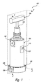
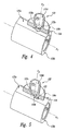
- Figure 1 is an isometric view of a constant flow valve assembly in accordance with an embodiment of the present invention.
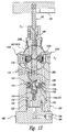
- FIG. 2 is an enlarged schematic cross-sectional view of the valve assembly taken substantially along lines 2-2 of Figure 1 .
- Figure 3 is an enlarged cross-sectional view of a portion of the valve assembly where indicated in Figure 2 and showing a restrictor assembly.
- Figure 4 is an enlarged isometric view and partial cutaway view of a geometry of a hollow cylinder and sealing pad shown removed from the restrictor assembly of Figures 2 and 3 and shown in an open-most condition.
- Figure 5 is an enlarged isometric view and partial cutaway view of the geometry of the hollow cylinder and sealing pad of Figure 4 and shown in a reduced flow position.
- Figure 6 is a schematic cross-sectional view of the valve assembly in accordance with another embodiment of the invention.
- Figure 7 an enlarged cross-sectional view of a portion of the valve assembly where indicated in Figure 6 and showing a restrictor assembly.
- Figure 8 is an enlarged isometric view and partial cutaway view of the geometry of a hollow cylinder and sealing pad shown removed from the restrictor assembly of Figures 6 and 7 and shown in the open-most condition and all flow through the receptacles and channels bypassed.
- Figure 9 is an enlarged isometric view of cascading notches and channels in the hollow cylinder of Figure 8 , with the sealing pad removed for purposes of clarity.
- Figure 10 is an enlarged isometric view and partial cutaway view of the geometry of the hollow cylinder and sealing pad of Figures 6 and 7 and in a reduced flow condition with three of the six notches bypassed.
- Figure 11 is an enlarged isometric view and partial cutaway view of the geometry of the hollow cylinder and sealing pad of Figures 6 and 7 shown with two of the six notches bypassed.
- Figure 12 is an enlarged isometric view and partial cutaway view of the geometry of the hollow cylinder and sealing pad of Figures 6 and 7 shown in the lowest flow condition with all flow passing through the six notches and interconnecting channels on each cylinder face in series.
- Figure 13 is a schematic cross-sectional view of the valve assembly in accordance with another embodiment of the invention.
- Figure 14 is an enlarged cross-sectional view of a portion of the valve assembly where indicated in Figure 13 and showing a restrictor assembly.
- Figure 15 is an enlarged isometric view and partial cutaway view of the geometry of the hollow cylinder and sealing pad shown removed from the valve assembly of Figures 13 and 14 for purposes of clarity and shown in the open-most condition.
- the present invention is directed toward flow control valves.
- numerous specific details are provided, such as particular valve configurations, to provide a thorough understanding of and an enabling description for embodiments of the invention.
- Those of ordinary skill in the art will recognize that the invention can be practiced without one or more of the specific details explained in the following description.
- well-known structures or operation are not shown or described in detail to avoid obscuring aspects of the invention.
- One aspect of the invention is directed to a flow control valve for providing a substantially constant flow of fluid through the valve.
- An aspect of the valve is to provide a substantially wide range of flow rate set points.
- the valve includes a valve body with a series of concentric bores and an end cap with an inlet in the end cap and an outlet in the valve body.
- the body contains a piston movably disposed in a piston bore and a shaft with a spool-shaped portion movably displaced in a second, third and fourth bore that are both concentric to the piston bore.
- a first flow passageway is provided between the inlet and a first restriction in a variable restrictor assembly, which share inlet fluid pressure (P1).
- the restrictor assembly is comprised of a first sealing pad with a hole in the center that slides over a face of a restrictor, and the face contains a notched opening.
- the sealing pad is urged against the face with a sealing pad spring.
- the notched opening is axially displaced relative to the sealing pad by moving the shaft's spool portion, which is powered by a handle turning a power screw.
- Another passageway is provided down stream of the first restriction and upstream of a mating cone-shaped pin and seat, which share intermediate fluid pressure (P2).
- P2 intermediate fluid pressure
- the cone-shaped pin is supported in the center of the piston with its shank concentric to the round opening in the seat, which is attached to the end of the shaft.
- An outlet passageway is provided down stream of the mating pin and seat to the outlet of the valve, which shares outlet fluid pressure (P3).
- a dynamic seal is positioned proximate to the piston and piston bore and separates the first passageway (with fluid pressure P1) from the second passageway (with fluid pressure P2).
- the dynamic seal defines a first effective area.
- the valve also includes a biasing member configured to urge the piston in a first direction toward the first passageway (P1).
- the inside diameter of the seat defines a second effective area which is substantially smaller than the first effective area.
- the valve is configured so that changes in pressure drop across the valve do not generally affect the flow rate of the fluid passing through the valve.
- the valve further includes an adjustable throttling member formed by the variable restrictor assembly comprised of the first restriction.
- the urging of the movably disposed piston and pin, which mates with the seat, creates a force balance across the piston that governs the pressure drop across the throttling member, which in turn maintains substantially constant flow with substantially large pressure drop fluctuations across the valve.
- the throttling member can be movable to vary the size of the opening in the first restriction.
- the movement of the shaft's distal end portion that creates a change in this opening also changes the force setting of the biasing member on the P2 side of the piston.
- the double purpose of the shaft's movement creates a substantially wide range of flow rate set point because, at the lowest flow rate, the smallest hole in the first restriction is exposed, and at this set point the lowest pressure drop across the first restriction exists.
- FIG 1 is an isometric view of valve assembly 100 for controlling the flow of a fluid in accordance with one embodiment of the invention.
- Figure 2 is an enlarged schematic cross-sectional view of the valve assembly 100 taken substantially along lines 2-2 of Figure 1 .
- Figure 3 is an enlarged schematic cross-sectional view of a portion of the valve assembly 100 where indicated in Figure 2 .
- the valve assembly 100 includes a valve body 102 and an inlet cap 108 that contains an inlet fitting 106 with an aperture defining a flow inlet 104.
- the valve body 102 contains an outlet fitting 110 with an aperture that defines a flow outlet 111.
- the valve body 102 contains a series of concentric bores common to longitudinal axis X1 that contain the piston 112, a piston biasing member 114, and a central shaft 125 with a spool portion 126. Attached to the lower end of the shaft 125 and axially aligned with the shaft is a seat 128 with a round inside diameter that mates with a cone-shaped end 119a of a pin 118 supported by the piston 112. A pin retainer 122 sitting atop the piston 112 centers the pin 118 and provides a shoulder 123a for a mating shoulder 119b of the pin 118 against which to slide.
- a pin spring 116 between the pin 118 and the piston 112 provides a force to keep the pin shoulder 119b in contact with the shoulder 123a and centered to the seat 128.
- the spring 116 also prevents the pin from "crashing" against the seat, as described in U.S. Patent No. 4,893,649 .
- the movement of the piston 112 and the pin 118 along the longitudinal axis X1 relative to the seat 128 is configured to maintain a constant fluid flow rate through the valve assembly 100 despite changes in the pressure drop across the valve 100, as described below in detail.
- a cup seal 124 is attached to the piston 112 and sealably engages the piston bore 130.
- the cup seal 124 separates fluid within the valve assembly's flow path, so inlet pressure (P1) is on one side of the cup seal (e.g., below the cup seal) and fluid at an intermediate pressure (P2) is on the other side of the cup seal (e.g., above the cup seal).
- inlet pressure (P1) is on one side of the cup seal (e.g., below the cup seal)
- fluid at an intermediate pressure (P2) is on the other side of the cup seal (e.g., above the cup seal).
- the fluid at intermediate pressure P2 is within a series of passageways down stream of a variable restrictor assembly 132 (discussed below).
- the cup seal 124 could be substituted with an "O" ring or other sealing member, such as a bellows or diaphragm.
- the piston 112 and pin 118 are urged away from the seat 128 along the longitudinal axis X1 with the biasing member 114.
- the biasing member 114 is a stack of disk springs, but other biasing devices, such as a coil spring mechanism, can be used to provide a biasing force against the piston 112 away from the seat 128.
- the arrangement of the spring-biased piston and pin mating with the seat 128 maintains substantially constant flow through the valve 100 independent of the pressure drop across the valve 100. assembly because the piston, pin and seat 128 maintain a substantially constant pressure drop across the variable restrictor assembly 132.
- the effective area A seat is enclosed by the mating inside diameter of the seat 128 and the cone-shaped end 119a of the pin 118.
- variable restrictor assembly 132 includes an inlet sealing pad portion 141, a restrictor 143, and an outlet sealing pad portion 145.
- the inlet sealing pad portion 141 includes a sealing pad 136a pressed against the restrictor 143 by a biasing member, such as a pad springs 140a.
- the pad spring 140a presses against a pad cap 142a, which is securely screwed into a threaded aperture in the valve body 102.
- the restrictor 143 includes a hollow cylinder 134 in the form of a sleeve fixed to the shaft 125 around the spool portion 126.
- the hollow cylinder 134 has a flat surface 135a against which the sealing pad 136a presses.
- the sealing pad 136a is urged along lateral axis X2 toward the first flat surface 135a on the hollow cylinder 134 by the pad springs 140a, which pushes on a pad pusher 138a between the pad springs and the sealing pad.
- the pad springs 140a can be of a spring design such as a Belleville washer, wave washer, coil spring, or other biasing device.
- the pad pusher 138a and the pad springs 140a are guided by the pad cap 142a.
- the sealing pad 136a is guided along the lateral axis X2 by the body 102 and a sealing pad guide 150a.
- the sealing pad guide 150a retains an inner seal 152a and an outer seal 154a which prevents fluid leakage and maintains the fluid flow at pressure P1 through the flow passageway 170, the inside diameter of the sealing pad 136a and the upstream side of the variable restrictor 143.
- the hollow cylinder 134 has a second flat engagement surface 135b.
- a second sealing pad 136b on the outlet side of the hollow cylinder 134 is pressed against the second flat surface 135b by second pad springs 140b, a second pad cap 142b, and a second pad pusher 138b.
- the pad pusher 138b and the sealing pad 136b are guided by a second sealing pad guide 150b so that the sealing pad 136b is also urged along the lateral axis x2 toward the restrictor 143.
- the fluid at pressure P1 flows from the lower portion of the piston bore 130 ( Figure 2 ) through the first flow passageway 170, into a central aperture 133d in the sealing pad 136a, and into the restrictor 143 via a through-hole 133a and associated surface restrictions on the first flat surface 135a to control flow rate, as discussed in detail below.
- the fluid exits the restrictor 143 via a through-hole 148 in the hollow cylinder 134 on the second flat surface 135b, and into a central aperture 136d in the second sealing pad 136b.
- the fluid entering the second sealing pad 136b is at a fluid pressure P2, which is less than the fluid pressure P1.
- the fluid flows from the second sealing pad 136b into a second flow passageway 174, which carries the fluid to the pin 118 and the seat 128 at the bottom portion of the shaft 125 ( Figure 2 ).
- the through-hole 148 on the outlet side is larger than the through-hole 133a on the inlet side, so surface restrictions on the second flat surface 135b are not needed for flow rate control. Because the restriction of through-hole 148 is quite small compared to the full flow condition of through-hole 133a, the pressure down stream of the through-hole 133a in the cavity 172 ( Figure 3 ) created between the inside of the hollow cylinder 134 and outer surface of the spool portion 126 and in the second sealing pad 136b is pressure P2. Because there is no meaningful pressure drop across the through-hole 148, additional seals are not needed around the second pad guide 150b.
- seals may be provided around the second pad guide 150b similar to the seals 152a and 154a discussed above.
- the fluid moving through the restrictor 143 is also blocked from migrating along the surface of the shaft 125 by upper and lower seals 156 and 158.
- the illustrated seals are groove seals disposed in annular grooves formed in the exterior of the shaft 125 above and below the hollow cylinder 134, such that the seals sealably engage the shaft and the valve body 102.
- the fluid at pressure P2 flows through the second flow passageway 174 into the upper portion of the piston bore 130 that contains the piston biasing member 114 and pin 118.
- the largest restriction in the valve assembly 100 is created by the cone-shaped end 119a of the pin 118 mating with seat 128 on the end of the shaft 125.
- the fluid flows through the restriction between the pin 118 and the seat 128, thereby creating another drop in fluid pressure from P2 to P3.
- Down stream of the mating pin 118 and seat 128 is the common fluid pressure P3, which is bound by the center and cross hole 175 in shaft 125, the seals 156 and 159 between the shaft and the valve body, and the outlet fitting 110, such that the pressure of the fluid exiting the valve assembly is at pressure P3.
- the hollow cylinder 134 is securely held on the shaft 125 about the spool portion 126, so that the hollow cylinder moves with the shaft as a unit along the longitudinal axis X1.
- one end of the hollow cylinder 134 is bound by a thrust washer 144 and snap ring 146, which is anchored to the spool portion 126.
- the opposite end of the hollow cylinder 134 is bound by a spring 160 that urges the hollow cylinder 134 toward the thrust washer 144.
- the spring 160 can be a coil spring, a wave washer, Belleville washer design, or other biasing member.
- the shaft 125 with the spool portion 126 is coupled to an adjustment handle 184 extending from the valve body 102.
- the handle 184 is coupled to a stem 182 and a power screw 180.
- the stem 182 and the power screw 180 rotate and move axially, thereby causing the spool portion 126, the cylinder 134, the snap ring 146, and the thrust washer 144 to move as a unit axially along longitudinal axis X1.
- This movement of the hollow cylinder 134 results in the first and second flat surfaces 135a and 135b moving longitudinally relative to the respective sealing pads 136a and 136b.
- the through-hole 133a on the inlet side of the hollow cylinder 134 and the through-hole 148 on the outlet side also move relative to the central apertures 133d and 136d in the sealing pads 136a and 136b, such that all or portions of the through-hole 133a may be exposed to the fluid flow through the sealing pad.
- Controlling the axial movement of the shaft 125 and the hollow cylinder 134 will control the position of the through-holes 133a and 148 relative to the sealing pads 136a and 136b, thereby controlling the fluid flow rate through the restrictor 143.
- the snap ring 146, thrust washer 144, and spring 160 provide a means of preventing backlash between the hollow cylinder 134 and the spool 126 during the axial movement.
- the product of thrust from turning of the end of the stem 182 against the end of the shaft 125 and the friction forces between these two surfaces cause the spool portion 126 to rotate as it moves along longitudinal axis X1.
- the hollow cylinder 134 allows the spool portion 126 to rotate, preventing the spool torque from overcoming the torque that the sealing pads 136a and 136b exert on the hollow cylinder 134, which in turn allows the sealing pads 136a and 136b to maintain contact with their mating flat surfaces 135a and 135b on the hollow cylinder 134. If the sealing pads 136a and 136b were to lose contact with the mating flat surfaces 135a and 135b respectively, the exposed flow area of the variable restrictor assembly 132 would dramatically increase causing an undesirable increase in the flow rate set point.
- Figure 4 and Figure 5 show an enlarged isometric view of the sealing pad 136a mating with the flat surface 135a on the inlet side of the hollow cylinder 134, wherein only half of the sealing pad 136a is shown for illustrative purposes.
- the footprint of the inside diameter of the sealing pad's central aperture 133d is shown as dashed line 133d relative to the through-hole 133a.
- the flat surface 135a of the hollow cylinder 134 also has a blind V-shaped notch 133b and a blind trench 133c recessed therein and coupled to the through-hole 133a.
- the trench 133c is configured to receive and direct fluid from the sealing pad's central aperture 133d to the notch 133b, and the notch directs the fluid into the through-hole 133a.
- the hollow cylinder 134 is shown in Figure 4 in a fully open position because the entire through-hole 133a is directly exposed to the sealing pad's central aperture 133d and fluid flowing there through. For this opening, the maximum spring tension in disk springs 114 ( Figure 2 ) exists, creating the maximum pressure drop through the through holes 133a and 133b, producing the maximum flow rate set point for the valve assembly 100.
- the sealing pad 136a and hollow cylinder 134 are illustrated in Figure 5 in a lower flow rate set point because a flange portion of the sealing pad 136a around the central aperture 133d is positioned to cover the entire through-hole 133a. In this position, only a portion of the V-shaped notch 133b and the trench 133c are within the footprint of the central aperture 133d and directly exposed to fluid flow there through. Accordingly, fluid will enter the exposed portions of the notch 133b and the trench 133c and will flow through the restriction created by the sealing pad 136a on the flat surface 135a over the notch 133b, and into the covered through-hole 133a for passage through the hollow cylinder 134.
- the through-hole 133a, the notch 133b, and the trench 133c are configured so that the fluid flow rate through the inlet side of the hollow cylinder 134 is directly related to how much of the trench, notch, and/or through-hole is within the footprint of the sealing pad's central aperture 133d and thereby directly exposed to the fluid flow there through. Accordingly, less exposed area of the trench/notch/through-hole provides a lower flow rate through the inlet side of the hollow cylinder, and more area exposed provides a greater flow rate.
- the minimum spring tension in disk springs 114 ( Figure 2 ) exists, creating the minimum pressure drop through the through hole 133b producing a lower flow rate set point than shown in Figure 4 .
- the restrictor 143 can have different configurations of trenches and/or notches to provide restrictions to fluid flow depending on the position of the shaft related to the sealing pads 136a and 136b.
- Figure 6 is a cross-sectional view of a valve assembly 100 in accordance with another embodiment
- Figure 7 is an enlarged cross-sectional view of a portion of the valve assembly where indicated in Figure 6 .
- the valve assembly 100 has generally the same components as those described above and shown in Figures 1-5 , so only the primary differences will be discussed.
- the restrictor 143 includes a flow restricting hollow cylinder 192 on the spool portion 126.
- the hollow cylinder 192 has a through-hole 198a in a flat surface 196a on the inlet side of the hollow cylinder 192.
- the sealing pad 136a on the inlet side is urged against the flat surface 196a as discussed above.
- the hollow cylinder 192 also has a through-hole 198b on a flat surface 196b on the outlet side of the hollow cylinder.
- the sealing pad 136b on the outlet side is urged against the flat surface 196b in the similar manner.
- the through-hole 198a on the inlet side has approximately the same diameter as the through-hole 198b on the outlet side.
- the hollow cylinder 192 includes a plurality of flow restricting members (discussed below) on the flat surface 196a on the inlet side and connected to the through-hole 198a, such that the flow rate through the restrictor can be adjusted by adjusting the position of the hollow cylinder 192 relative to central aperture 133d in the sealing pad 136a.
- flow restricting members can be provided on the flat surface 196b on the outlet side and connected to the through-hole 198b.
- the through-hole 198a is connected to a blind V-shaped notch 200a machined into the flat surface 196a on the outside of the hollow cylinder 192 on the inlet side.
- Figure 9 is an enlarged isometric view of the hollow cylinder 192 showing the flat surface 196a, the through-hole 198a, and the flow restricting members.
- These flow restricting members include a plurality of blind receptacles, referred to as trenches 202a and 206a, interconnected by a plurality of blind channels 204a.
- the trenches 202a in the illustrated embodiment are radially and longitudinally offset from each other and run generally parallel to the longitudinal axis X1.
- Each trench 202a is connected to an adjacent trench or to the through-hole 198a by a channel 204a, thereby forming a series of cascading flow restrictions configured to allow for fluid flow through each trench in series to the through-hole 198a.
- the trenches 202a in the illustrated embodiment are deeper than the connecting channels 204a.
- Figure 10 is an isometric view of the sealing pad 196a and the hollow cylinder 192 in a configuration wherein a portion of the V-shaped notch 200a, the through-hole 198a, and approximately three of the trenches 202a are covered by the flange portion of the sealing pad 136a. Three of the channels 204a are within the footprint of the central aperture 133d, and thereby bypassed from restricting the flow through the hollow cylinder. At this set point, the flow at flat surface 196a and into the through-hole has a parallel path. The majority of the flow passes into the through-hole 198a via the exposed portion of the V-shaped notch 200a.
- Another portion of the flow moves through the covered trenches 202a and channels 204a in series after the flow from the central aperture 133d into one of the trenches 202a that is exposed or only partially covered by the flange of the sealing pad 136a.
- the flow then passes through a channel 204a in the side of the partially covered trench 202a, then to the first completely covered trench 202a, then the next channel 204a, then to the next covered trench 202a, and to the next channel 204a where the flow enters through-hole 198a.
- This "in-series" restrictive flow path of channels 204a and trenches 202a is a parallel path to the flow passing through the partially exposed V-shaped notch and into the through-hole.
- Figure 10 illustrates a reduced flow set point as compared to the flow set point illustrated in Figure 8 , because less flow area is exposed on the flat surface 196a, and the piston springs 114 ( Figure 6 ) are loaded less than in the position shown in Figure 8 , thereby producing a smaller pressure drop across the inlet side of the hollow cylinder.
- Figure 11 is an isometric view of the sealing pad 196a and the hollow cylinder 192 in a configuration wherein the V-shaped notch 200a and the through-hole 198a are fully covered by the flange portion of the sealing pad 136a. Two of the channels 204a are bypassed and the remaining four channels and associated trenches are covered, thereby restricting the flow through the inlet side of the hollow cylinder 192. At this set point, the flow at the flat surface 196a has only an in-series path to the through-hole 198a, wherein the flow passes into a portion of a trench 202a only partially covered by the sealing pad 136a. The flow then passes through the four channels 204a and three trenches 202 in series.
- the configuration illustrated in Figure 11 provides a reduced flow set point compared to the configuration shown in Figure 10 , because there is less flow area exposed on the flat surface 196a.
- the piston springs 114 ( Figure 6 ) are loaded less than in the position shown in Figure 10 , thereby producing a smaller pressure drop across the inlet side of the hollow cylinder 192.
- Figure 12 is an isometric view of the sealing pad 196a and the hollow cylinder 192 in a set point configuration wherein the V-shaped notch 200a, the through-hole 198a, and all of the channels 204a are fully covered by the sealing pad.
- the flow at flat surface 196a has only a series path to the through-hole 198a where the flow passes into an uncovered portion of the longest trench 206a. The flow then passes in series through the six channels 204a and the five interspersed trenches 202a.
- Figure 12 provides a reduced flow set point compared to the set point illustrated in Figure 11 , because there is less flow area exposed on the flat surface 196a, and piston springs 114 ( Figure 6 ) are loaded less than in the position shown in Figure 11 , thereby producing a smaller pressure drop across the inlet side of the hollow cylinder 192.
- Figure 12 illustrates a configuration wherein the flow rate set point is changed entirely by changing the tension in the piston springs 114.
- the sealing pad 136b shown in Figures 6 and 7 on the outlet side of the hollow cylinder 192 mates with the flat surface 196b shown in Figure 8 .
- Channels 204b, trenches 202b, and a V-shaped groove 200b referenced in Figure 8 are substantially identical to the channels 204a, trenches 202a, and V-shaped notch 200a provided in the flat surface 196a on the inlet side of the hollow cylinder 192 discussed above.
- the channels 204b, notches 202a, and V-shaped groove 200b are positioned to be selectively exposed to the central aperture 133d in the sealing pad 136b or covered by the flange portion of the sealing pad, so as to provide a variable fluid resistor 194b that provides flow resistance to the fluid flow exiting hollow cylinder 192 and flowing into the sealing pad 136b and into the flow passageway 174 similar to the flow resistance configuration on the inlet side of the restrictor.
- the second fluid resistor 194b on the outlet side can substantially increase the fluid resistance for the lower flow rate set points, thereby allowing very low flow rates to be achieved with the largest cross-sectional flow passages.
- the fluid flows from the inlet pressure P1 then passes in series through part of the elongated trench 206a, five trenches 202a and the interspersed six channels 204a and then into the through-hole 198a.
- the flow then passes through the inlet side of the hollow cylinder 192, and through the cavity 172 created by the inside diameter of the hollow cylinder and the outside diameter of the recessed spool portion 126.
- the flow passes out the through-hole 198b, then through six channels 204b and the interspersed five trenches 202b, all in series, and then into the central aperture 133d in the sealing pad 136b.
- the combined effect of the channels and trenches on the hollow cylinder is to produce a sequence of multiple flow restrictions in series that steps the fluid pressure down from P1 to P2.
- the fluid resistance for a restrictor 194a can be, but does not have to be, substantially identical to the resistor 194b.
- seals 152b and 154b adjacent to the sealing pad 136b and the pad guide 150b. These additional seals help prevent leaks out of cavity 172 through the ends of the hollow cylinder 192 into cavity 172 which is at fluid pressure P2, thereby preventing an inadvertent bypass of any of the six fluid resistors that make up fluid resistor 194b.
- Figures 13 and 14 are cross-sectional views of another embodiment of the valve assembly 100.
- the sealing pads 136a and 136b are pressed into direct engagement with the shaft 125, rather than against the hollow cylinder 192 discussed above.
- the shaft has an aperture 266 extending there through between the sealing pads 136a and 136b. Accordingly, this portion of the shaft engaged by the sealing pads 136a and 136b does not rotate when the handle 184 and/or power screw 180.
- Figure 15 is an enlarged isometric view of the sealing pad 136a mating with the surface 262a on the inlet side of the shaft 125.
- a series of notches and channels are provided on the surface of the shaft 125, similar to those illustrated in Figure 9 and discussed above, but the aperture 266 passes completely through the shaft.
- the aperture 266 can communicate with a series of cascading notches and channels in the shaft adjacent to the sealing pad on the outlet side of the restrictor.
Landscapes
- Engineering & Computer Science (AREA)
- General Engineering & Computer Science (AREA)
- Physics & Mathematics (AREA)
- General Physics & Mathematics (AREA)
- Automation & Control Theory (AREA)
- Mechanical Engineering (AREA)
- Safety Valves (AREA)
- Magnetically Actuated Valves (AREA)
Claims (7)
- Konstantdurchfluss-Ventilanordnung, umfassend:einen ersten Fluidleitungsweg (170), der dazu eingerichtet ist, Fluid mit einem ersten Fluiddruck (P1) zu befördern;eine Kolbenkammer, die wenigstens einen Abschnitt hat, der dazu eingerichtet ist, Fluid mit einem zweiten Fluiddruck (P2) aufzunehmen, der geringer ist als der erste Fluiddruck (P1);einen zweiten Fluidleitungsweg (174), der mit dem Abschnitt der Kolbenkammer verbunden und dazu eingerichtet ist, Fluid mit dem zweiten Fluiddruck (P2) zu befördern;einen dritten Fluidleitungsweg (175), der dazu eingerichtet ist, Fluid mit einem dritten Fluiddruck (P3) zu befördern, der geringer ist als der erste und der zweite Fluiddruck (P1, P2); undeine einstellbare Begrenzeranordnung (132) zwischen dem ersten und dem zweiten Fluidleitungsweg (170, 174), wobei die Begrenzeranordnung (132) einen Einlassabschnitt (141), einen Auslassabschnitt (145) und einen Begrenzer (143) mit einem sich dazwischen erstreckenden Fluidleitungsweg hat, der Einlassabschnitt (141) so angeordnet ist, dass er Fluid mit dem ersten Fluiddruck (P1) aus dem ersten Fluidleitungsweg (170) aufnimmt und das Fluid zu dem Begrenzer (143) leitet, der Auslassabschnitt (145) derart angeordnet ist, dass er Fluid von dem Begrenzer (143) aufnimmt und das Fluid zu dem zweiten Fluidleitungsweg (174) mit dem zweiten Fluiddruck (P2) leitet, der Begrenzer (143) einen Eintrittsabschnitt und einen Austrittsabschnitt des Fluidleitungsweges hat und der Begrenzer (143) beweglich ist, um die Stellung des Eintritts- und des Austrittsabschnittes in Bezug auf den Einlass- und den Auslassabschnitt (141, 145) einzustellen, um eine Fluidfließrate des Fluides durch den Fluidleitungsweg zu dem zweiten Fluidleitungsweg (174) einzustellen und das vorgespannte Ventilelement für eine konstante Fließrate des Fluids durch die Ventilanordnung automatisch einzustellen;dadurch gekennzeichnet, dassdie Konstantdurchfluss-Ventilanordnung weiterhin umfasst:einen Kolben (112) der gleitfähig in der Kolbenkammer aufgenommen ist; undein vorgespanntes Ventilelement, das einen Ventilsitz (128) benachbart dem dritten Leitungsweg (175), einen Ventilkörper (118, 119a) und ein Vorspannelement (116) hat, das mit dem Kolben (112) gekoppelt ist, wobei der Ventilkörper (118, 119a) durch das Vorspannelement (116) auf den Ventilsitz (128) gedrückt wird und dazu eingerichtet ist, einen im wesentlichen konstanten Fluidfluss zu dem dritten Leitungsweg (175) über den Ventilsitz (128) im wesentlichen unabhängig von den Druckunterschieden zwischen dem zweiten und dem dritten Fluiddruck (P2, P3) bereitzustellen.
- Anordnung nach Anspruch 1, bei der der Begrenzer (143) eine Außenoberfläche (135a) hat, der Fluidleitungsweg den Eintrittsabschnitt umfasst, der durch wenigstens eine Blindvertiefung (133b) in der Außenoberfläche (135a) ausgebildet und in Fluidverbindung mit einem Durchgangsloch (133a) steht, und der Begrenzer (143) beweglich ist, um es dem Einlassabschnitt zu gestatten, mit wenigstens einem Abschnitt des Eintrittsabschnittes in Eingriff zu gelangen, um den Fluidfluss durch den Begrenzer (143) einstellbar zu begrenzen und die Fluidfließrate durch die einstellbare Begrenzeranordnung (132) zu steuern.
- Anordnung nach Anspruch 1, bei der der Begrenzer (143) eine Außenoberfläche (196a) hat, der Fluidleitungsweg den Eintrittsabschnitt umfasst, der durch eine Vielzahl von Blindvertiefungen (202a) ausgebildet ist, die durch wenigstens einen Blindkanal (204a) verbunden sind und mit einem Durchgangsloch (198a) in Fluidverbindung stehen, und der Begrenzer (143) beweglich ist, um es dem Einlassabschnitt zu gestatten, mit wenigstens einem Abschnitt des Eintrittsabschnittes in Eingriff zu gelangen, um den Fluidfluss in die Blindvertiefungen (202a), den Blindkanal (204a) oder das Durchgangsloch (198a) einstellbar zu begrenzen und die Fluidfließrate durch die einstellbare Begrenzeranordnung (132) zu steuern.
- Anordnung nach Anspruch 3, bei der der Begrenzerkörper beweglich ist, so dass wenigstens ein Abschnitt des Durchgangsloches (198a) unverdeckt bleibt und wenigstens eine Blindvertiefung (202a), die dem Durchgangsloch (198a) benachbart ist, vollständig verdeckt ist, wodurch das Durchgangsloch (198a) gleichzeitig parallel ein Fluid von der verdeckten Blindvertiefung (202a) und direkt von dem Einlassabschnitt aufnimmt.
- Anordnung nach Anspruch 1, bei der der Begrenzer (143) eine Außenoberfläche (262a) mit dem darauf befindlichen Eintrittsabschnitt (266) umfasst und der Einlassabschnitt ein Körpersegment (136a) mit einer Öffnung (133d) in Fluidverbindung mit dem ersten Fluidleitungsweg (170) und mit dem Eintrittsabschnitt umfasst, wobei das Körpersegment (136a) mit der Außenoberfläche (262a) des Begrenzerkörpers derart in Eingriff steht, dass wenigstens ein Abschnitt der Öffnung (133d) in direkter Fluidverbindung mit dem Eintrittsabschnitt steht.
- Anordnung nach Anspruch 1, weiterhin umfassend eine externe Einstellvorrichtung (180, 182, 184), die mit der Begrenzeranordnung gekoppelt ist, wobei die Einstellvorrichtung (180, 182, 184) derart betätigt werden kann, dass sie die Begrenzeranordnung (132) bewegt, um so die Stellung des Begrenzers (143) relativ zu dem Einlassabschnitt zu ändern.
- Anordnung nach Anspruch 1, bei der der Begrenzer (143) eine Außenoberfläche (196b) hat, der Fluidleitungsweg den Austrittsabschnitt umfasst, der durch wenigstens eine Blindvertiefung (200b) in der Außenoberfläche (196b) ausgebildet ist und mit einem Durchgangsloch (198b) in Fluidverbindung steht, und der Begrenzer (143) beweglich ist, um es dem Auslassabschnitt zu gestatten, mit wenigstens einem Abschnitt des Austrittsabschnittes in Eingriff zu gelangen, um den Fluidfluss durch den Begrenzer (143) einstellbar zu begrenzen und die Fluidfließrate durch die einstellbare Begrenzeranordnung (132) zu steuern.
Applications Claiming Priority (2)
| Application Number | Priority Date | Filing Date | Title |
|---|---|---|---|
| US79574806P | 2006-04-27 | 2006-04-27 | |
| PCT/US2007/067688 WO2007127949A2 (en) | 2006-04-27 | 2007-04-27 | Flow control valve |
Publications (3)
| Publication Number | Publication Date |
|---|---|
| EP2021892A2 EP2021892A2 (de) | 2009-02-11 |
| EP2021892A4 EP2021892A4 (de) | 2012-04-11 |
| EP2021892B1 true EP2021892B1 (de) | 2013-02-20 |
Family
ID=38656427
Family Applications (1)
| Application Number | Title | Priority Date | Filing Date |
|---|---|---|---|
| EP07761509A Not-in-force EP2021892B1 (de) | 2006-04-27 | 2007-04-27 | Stromventil |
Country Status (4)
| Country | Link |
|---|---|
| US (4) | US7770595B2 (de) |
| EP (1) | EP2021892B1 (de) |
| NO (1) | NO337256B1 (de) |
| WO (1) | WO2007127949A2 (de) |
Families Citing this family (10)
| Publication number | Priority date | Publication date | Assignee | Title |
|---|---|---|---|---|
| WO2007127949A2 (en) * | 2006-04-27 | 2007-11-08 | Sko Flo Industries, Inc. | Flow control valve |
| US9052715B2 (en) | 2010-10-05 | 2015-06-09 | Sko Flo Industries, Inc. | Flow rate controller for high flow rates and high pressure drops |
| CH708204A1 (de) * | 2013-06-12 | 2014-12-15 | Belimo Holding Ag | Druckausgleichseinsatz. |
| US9573808B2 (en) | 2013-07-31 | 2017-02-21 | Schlumberger Technology Corporation | Aqueous solution and method for use thereof |
| US9796490B2 (en) * | 2013-10-24 | 2017-10-24 | Schlumberger Technology Corporation | Aqueous solution and method for use thereof |
| US9920606B2 (en) | 2013-07-31 | 2018-03-20 | Schlumberger Technology Corporation | Preparation method, formulation and application of chemically retarded mineral acid for oilfield use |
| NO20131401A1 (no) * | 2013-10-05 | 2014-11-10 | Obs Tech As | Strømningskontrollventil |
| ITMI20132133A1 (it) * | 2013-12-19 | 2015-06-20 | Vir Valvoindustria Ing Rizzio S P A | Valvola di bilanciamento dinamico per controllo della portata indipendente dalla pressione |
| US10394254B2 (en) * | 2016-05-26 | 2019-08-27 | Sko Flo Industries, Inc. | Multi-stage flow control assemblies |
| US10126762B2 (en) | 2017-02-07 | 2018-11-13 | Woodward, Inc. | Velocity and pressure equalization ports |
Family Cites Families (176)
| Publication number | Priority date | Publication date | Assignee | Title |
|---|---|---|---|---|
| US988495A (en) | 1908-05-08 | 1911-04-04 | C P Power Company | Fluid-operated valve. |
| US1517877A (en) * | 1922-06-27 | 1924-12-02 | H S B W Cochrane Corp | Valve |
| US1586834A (en) | 1925-02-27 | 1926-06-01 | Augusta N Ormsby | Meter |
| US1777261A (en) | 1928-05-17 | 1930-09-30 | Grainger James Edward | Valve |
| US2071036A (en) * | 1930-08-30 | 1937-02-16 | Hobart Mfg Co | Washing machine |
| US2101356A (en) * | 1937-04-19 | 1937-12-07 | Zak William | Orifice dial valve |
| US2626810A (en) * | 1945-12-22 | 1953-01-27 | Galera Jose | Rotary and reciprocating multiple valve |
| US2650613A (en) * | 1948-05-15 | 1953-09-01 | Brumbaugh Isaac Vernon | Graduated universal valve for gas appliances with slitted sleeve |
| US2693701A (en) | 1949-08-25 | 1954-11-09 | Sprague Meter Company | Gas meter diaphragm |
| US2751935A (en) | 1954-12-13 | 1956-06-26 | Cutler Hammer Inc | Diaphragm elements |
| US3079953A (en) | 1962-03-19 | 1963-03-05 | Giannini Controls Corp | Pressure responsive element |
| US3434395A (en) | 1964-10-26 | 1969-03-25 | Holley Carburetor Co | Pressure responsive mechanism |
| US3344805A (en) | 1965-03-24 | 1967-10-03 | Fischer & Porter Co | Automatic flow rate control system |
| US3575088A (en) | 1968-08-30 | 1971-04-13 | Gen Motors Corp | Vacuum modulator |
| US3613517A (en) | 1970-03-18 | 1971-10-19 | Emery Co A H | Tension load cell |
| US3677288A (en) | 1970-10-08 | 1972-07-18 | Thomas B Martin | Flow control valve |
| US3853143A (en) | 1971-01-29 | 1974-12-10 | Danfoss As | Flexible diaphragm air damper |
| US3954124A (en) * | 1973-12-05 | 1976-05-04 | Self Richard E | High energy loss nested sleeve fluid control device |
| US3971411A (en) * | 1974-03-07 | 1976-07-27 | Masoneilan International, Inc. | Variable resistance type throttling trim |
| US3908698A (en) * | 1974-03-07 | 1975-09-30 | Hans D Baumann | Variable resistance type throttling trim |
| DE2441048C3 (de) | 1974-08-27 | 1978-06-29 | Robert Bosch Gmbh, 7000 Stuttgart | Membranventil |
| US3969991A (en) | 1975-03-03 | 1976-07-20 | Bellofram Corporation | Rolling diaphragm and rolling diaphragm devices |
| US4096747A (en) | 1975-10-14 | 1978-06-27 | Gilson Paul R | Digital output, positive displacement flow meter |
| FR2339203A1 (fr) | 1976-01-20 | 1977-08-19 | Bronzavia Sa | Dispositif de reglage de la pression differentielle entre deux points de pressions differentes d'un circuit de fluide |
| US4015626A (en) | 1976-01-22 | 1977-04-05 | Thordarson, Inc. | Constant flow valve for low flow rates |
| DE2615009C2 (de) | 1976-04-07 | 1983-08-11 | Fa. Ernst Flitsch, 7012 Fellbach | Antrieb für einen Durchflußregelhahn |
| IT1062952B (it) | 1976-05-26 | 1985-02-11 | Pirelli | Valvola regolatrice di flusso |
| US4055084A (en) | 1976-07-08 | 1977-10-25 | Hans Wilde | Liquid flow meter construction |
| IL50771A (en) | 1976-10-27 | 1988-08-31 | Bron Dan | Fluid flow-rate control device |
| DE2648955C2 (de) | 1976-10-28 | 1983-01-05 | Robert Bosch Gmbh, 7000 Stuttgart | Membranventil |
| US4177830A (en) | 1976-12-21 | 1979-12-11 | Bourns, Inc. | Valve assembly permitting independent peak flow and decay rate control of periodic gas flows |
| US4343305A (en) | 1977-10-14 | 1982-08-10 | Dan Bron | Adjustable-rate, constant output infusion set |
| JPS5471432A (en) * | 1977-11-17 | 1979-06-08 | Sotokazu Rikuta | Flow rate constant value automatic control valve |
| US4176686A (en) | 1977-11-19 | 1979-12-04 | Concordia Fluidtechnik Gmbh | Flow control valve for liquids |
| IT1113795B (it) | 1977-12-01 | 1986-01-20 | Pirelli | Valvola regolatrice di flusso perfezionata |
| US4361147A (en) | 1979-01-22 | 1982-11-30 | Master Medical Corporation | Flow control device for administration of intravenous fluids |
| US4228777A (en) | 1979-02-01 | 1980-10-21 | The Bendix Corporation | Fuel control |
| US4429708A (en) | 1979-03-22 | 1984-02-07 | Trw Inc. | Fluid flow control |
| US4241757A (en) | 1979-03-26 | 1980-12-30 | Dan Bron | Flow regulator |
| IL56948A0 (en) | 1979-03-26 | 1979-05-31 | Bron D | Flow rate regulator |
| US4234013A (en) | 1979-06-01 | 1980-11-18 | Sotokazu Rikuta | Control valve for keeping the rate of flow at a fixed value |
| DE2929389C2 (de) * | 1979-07-20 | 1984-05-17 | Machinefabriek Mokveld B.V., 2800 Gouda | Regelventil |
| US4278010A (en) | 1979-07-23 | 1981-07-14 | United Technologies Corporation | Fluid flow regulator valve |
| US4406442A (en) * | 1980-01-22 | 1983-09-27 | International Harvester Co. | Rotary valve |
| US6610830B1 (en) * | 1980-07-01 | 2003-08-26 | Hoffman-La Roche Inc. | Microbial production of mature human leukocyte interferons |
| US4319735A (en) * | 1980-07-22 | 1982-03-16 | Stanadyne, Inc. | Faucet valves |
| US4395018A (en) * | 1980-07-30 | 1983-07-26 | Stanadyne, Inc. | Valve member with fixed seal shutoff |
| US4372147A (en) | 1981-03-17 | 1983-02-08 | Waugh Controls Corporation | Flow meter prover apparatus and method |
| US4541454A (en) | 1981-12-07 | 1985-09-17 | Sturman Oded E | Pressure regulators |
| US4422470A (en) | 1982-07-01 | 1983-12-27 | The Cessna Aircraft Company | Flow limiting valve |
| US4449548A (en) | 1982-09-23 | 1984-05-22 | United Technologies Corporation | Flow control device |
| DE3246738A1 (de) | 1982-09-28 | 1984-03-29 | Dr. H. Tiefenbach Gmbh & Co, 4300 Essen | Mit eigenmedium gesteuertes hydraulikventil mit einstellbarem durchlassquerschnitt |
| GB8306852D0 (en) | 1983-03-12 | 1983-04-20 | Lucas Ind Plc | Hydraulic flow control valve |
| US4513777A (en) | 1983-08-22 | 1985-04-30 | General Motors Corporation | Pressure compensated flow control valve assembly for fluids containing finely divided solids |
| US4549426A (en) | 1983-10-28 | 1985-10-29 | Smith Meter, Inc. | Compact flow prover |
| FR2557947B1 (fr) | 1984-01-06 | 1988-04-15 | Sereg Soc | Diaphragme ondule pour capteur de pression |
| US4549572A (en) | 1984-09-24 | 1985-10-29 | General Motors Corporation | Pressure compensated fluid flow regulator |
| US4634095A (en) | 1985-07-26 | 1987-01-06 | Taylor Julian S | Multiple stage choke valve |
| DE3625428A1 (de) | 1985-08-10 | 1988-02-04 | Rexroth Mannesmann Gmbh | Proportional-drosselventil |
| US4679592A (en) | 1985-10-07 | 1987-07-14 | Teledyne Industries, Inc. | Valve seat design to reduce cavitation |
| DE3621746A1 (de) * | 1986-06-28 | 1988-01-21 | Hubert Skibowski | Absperrarmatur |
| US4699358A (en) * | 1986-08-15 | 1987-10-13 | Stanadyne, Inc. | Faucet valve with noise reduction structure |
| IN167170B (de) | 1987-05-14 | 1990-09-15 | Hitachi Construction Machinery | |
| US4829808A (en) | 1987-05-15 | 1989-05-16 | West Theodore V | Flow meter prover apparatus and method |
| US5450873A (en) | 1988-04-07 | 1995-09-19 | Palmer; David W. | System for controlling flow through a process region |
| DE3919299A1 (de) | 1988-06-28 | 1990-01-04 | Landis & Gyr Ag | Wellmembran |
| US5000219A (en) * | 1988-06-30 | 1991-03-19 | Systems Specialties | Fluid flow control regulator |
| US4893649A (en) * | 1988-09-30 | 1990-01-16 | Skoglund Paul K | Constant flow rate controller valve |
| DE3908377A1 (de) | 1989-03-15 | 1990-09-27 | Fluidtech Gmbh | 2-wege-stromventil |
| US5190075A (en) | 1989-03-28 | 1993-03-02 | Tentler Michael L | Viscosity-insensitive mechanical fluid flow regulator |
| US4987740A (en) | 1989-04-03 | 1991-01-29 | General Motors Corporation | Assured venting master cylinder diaphragm apparatus and method |
| US5061454A (en) | 1989-06-22 | 1991-10-29 | The United States Of America As Represented By The Secretary Of The Army | High pressure spray injector |
| IL90950A (en) | 1989-07-12 | 1992-08-18 | Bron Dan | Low-output flow regulator |
| US4921547A (en) | 1989-07-26 | 1990-05-01 | Vickers Incorporated | Proportional priority flow regulator |
| US5143116A (en) * | 1989-12-11 | 1992-09-01 | Skoglund Paul K | Flow regulating valve and system using the same |
| US5234025A (en) | 1989-12-11 | 1993-08-10 | Skoglund Paul K | Partitioned flow regulating valve |
| US5282490A (en) | 1989-12-18 | 1994-02-01 | Higgs Robert E | Flow metering injection controller |
| ES2077759T3 (es) | 1990-10-31 | 1995-12-01 | Inventio Ag | Barrera de luz de horquilla de doble canal con una construccion "failsafe". |
| US5408886A (en) | 1991-05-29 | 1995-04-25 | Gilian Instrument Corp. | Positive displacement piston flow meter with internal valve |
| US5299775A (en) | 1991-10-15 | 1994-04-05 | Kolze, Inc. | Flow modulating control valve assembly |
| US5214939A (en) | 1991-11-25 | 1993-06-01 | Carrier Corporation | Variable area refrigerant expansion device having a flexible orifice |
| NO178839C (no) | 1991-11-25 | 1996-06-12 | Ottestad Nils T | Strömningsregulator for opprettholdelse av en stabil strömningsmengde av et fluidum |
| FR2693248B1 (fr) * | 1992-07-03 | 1994-09-23 | Roger Bey | Vanne du type à bille ou à boisseau équipé d'un insert. |
| US5251655A (en) | 1992-07-06 | 1993-10-12 | Wilshire Partners | Flow control valves for post-mix beverage dispensers |
| US5255711A (en) | 1992-08-28 | 1993-10-26 | Hughes Aircraft Company | Spring-loaded pressure regulating valve including rolling diaphragm and compensation for variation of spring force with diaphragm displacement |
| GB9218593D0 (en) | 1992-09-02 | 1992-10-14 | Kinetrol Ltd | Flow control devices |
| US5249773A (en) | 1992-11-12 | 1993-10-05 | Kohler Co. | Fluid flow regulating valve |
| US5295506A (en) | 1992-12-14 | 1994-03-22 | Smith Allan L | Flow control apparatus |
| US5280805A (en) | 1993-01-19 | 1994-01-25 | Skoglund Paul K | Flow control valve having adjustable sleeve for varying flow rate |
| IL105071A (en) | 1993-03-16 | 1996-11-14 | Bron Dan | Adjustable rate flow regulator |
| AU667629B2 (en) | 1993-05-27 | 1996-03-28 | Sumitomo Electric Industries, Ltd. | Changeover valve and flow control valve assembly having the same |
| US5301713A (en) | 1993-06-01 | 1994-04-12 | Skoglund Paul K | Flow control valve having adjustable piston for varying flow rate |
| US5487405A (en) | 1993-06-01 | 1996-01-30 | Skoglund; Paul K. | Flow control valve having flow adjustable by variable ring |
| US5971012A (en) | 1993-06-01 | 1999-10-26 | Skoglund; Paul K. | Constant flow control valve having matable piston sleeve and outlet cover |
| US5642752A (en) | 1993-08-23 | 1997-07-01 | Kabushiki Kaisha Yokota Seisakusho | Controllable constant flow regulating lift valve |
| FR2710961B1 (fr) | 1993-10-05 | 1995-11-17 | Alliedsignal Europ Services | Valve à seuil à poussoir rétractile. |
| US5383489A (en) | 1993-10-26 | 1995-01-24 | Flow Design, Inc. | Flow control valve with enhanced flow control piston |
| US5727529A (en) | 1994-01-14 | 1998-03-17 | Walbro Corporation | Pressure control valve for a fuel system |
| US5377955A (en) * | 1994-02-15 | 1995-01-03 | Baker; Dwight | Gate valve |
| US5427139A (en) | 1994-05-06 | 1995-06-27 | A & H Enterprises, Inc. | Metering valve with adjustable floating piston and pin assembly |
| DE4427905A1 (de) | 1994-08-06 | 1996-02-08 | Teves Gmbh Alfred | Ventilvorrichtung, insbesondere für hydraulische Bremsanlagen mit Blockier- und/oder Antriebsschlupfregelung |
| US5718410A (en) | 1995-01-27 | 1998-02-17 | Baumann; Hans D. | Small flow control valve with cartridge type seating arrangement |
| US5562002A (en) | 1995-02-03 | 1996-10-08 | Sensidyne Inc. | Positive displacement piston flow meter with damping assembly |
| US5803119A (en) * | 1995-02-08 | 1998-09-08 | Control Components Inc. | Fluid flow control device |
| DE19507086C2 (de) | 1995-03-01 | 1997-01-30 | Danfoss As | Wasserhydraulik-Regelventil |
| DK0751448T3 (da) | 1995-06-28 | 2001-06-18 | Siemens Building Tech Ag | Gennemstrømnings-reguleringsventil |
| US5655568A (en) | 1995-08-08 | 1997-08-12 | Bhargava; Raj | Passive flow regulating device |
| US5662142A (en) | 1995-09-11 | 1997-09-02 | Gentex Corporation | Valve flapper with bands of different deflectibility |
| US5673607A (en) | 1995-10-19 | 1997-10-07 | Diacom Corporation | Rolling head diaphragm |
| US5615708A (en) | 1995-10-23 | 1997-04-01 | Fisher Controls International, Inc. | Flow control valve with non-plugging multi-stage valve trim |
| US5634491A (en) | 1995-10-23 | 1997-06-03 | Benedict; Charles | Flow control valve assembly |
| DE19539521C2 (de) | 1995-10-24 | 1999-01-07 | Mannesmann Rexroth Ag | Stromregelventil |
| US6026850A (en) | 1996-02-27 | 2000-02-22 | Global Agricultural Technology And Engineering, Llc | Pressure regulating valve |
| US5931186A (en) | 1996-03-01 | 1999-08-03 | Skoglund; Paul K. | Fluid flow control valve and actuator for changing fluid flow rate |
| US5853022A (en) | 1996-04-10 | 1998-12-29 | Fisher Controls International, Inc. | Valve actuator with instrument mounting manifold |
| KR100445944B1 (ko) | 1996-05-29 | 2004-11-03 | 가부시끼가이샤 요꼬따 세이사꾸쇼 | 자동 조정 밸브 장치 |
| US5695169A (en) * | 1996-06-28 | 1997-12-09 | Brass-Craft Manufacturing Company | Stop valve with sturdy handle connection |
| US5680889A (en) * | 1996-09-23 | 1997-10-28 | Dresser Industries, Inc. | Low noise ball valve assembly |
| US5904177A (en) | 1997-03-17 | 1999-05-18 | Marotta Scientific Controls, Inc. | Fluid flow control device |
| EP0872404B1 (de) | 1997-04-09 | 2004-01-02 | Toyoda Koki Kabushiki Kaisha | Strömungssteuereinrichtung für Servolenkung |
| US6062534A (en) | 1997-04-25 | 2000-05-16 | Fisher Controls International | Double acting rotary valve actuator |
| DE19725198A1 (de) | 1997-06-14 | 1998-12-17 | Bosch Gmbh Robert | Brennstoffeinspritzventil |
| US5964408A (en) | 1997-07-14 | 1999-10-12 | Musson; Cyril D. | Irrigation sprinkler and valve with flushing system |
| US5878766A (en) | 1997-10-20 | 1999-03-09 | Vickers, Incorporated | Pressure compensated flow control valve |
| EP0911714A1 (de) | 1997-10-20 | 1999-04-28 | Electrowatt Technology Innovation AG | Durchfluss-Regelventil mit integriertem Druckregler |
| US6298879B1 (en) | 1997-10-21 | 2001-10-09 | Masco Corporation Of Indiana | Stem valve stopper |
| US5979495A (en) | 1997-12-22 | 1999-11-09 | Taube; Frank A. | Adjustable low flow high pressure regulator |
| KR100396806B1 (ko) | 1998-02-24 | 2003-09-02 | 미쓰비시덴키 가부시키가이샤 | 전동식 유량제어 밸브 |
| US6824379B2 (en) | 1998-04-21 | 2004-11-30 | Synventive Molding Solutions, Inc. | Apparatus for utilizing an actuator for flow control valve gates |
| US6026849A (en) | 1998-06-01 | 2000-02-22 | Thordarson; Petur | High pressure regulated flow controller |
| US5988211A (en) | 1998-07-06 | 1999-11-23 | Randolph W. Cornell | I.V. flow controller |
| US6568656B1 (en) | 1998-07-09 | 2003-05-27 | Sporlan Valve Company | Flow control valve with lateral port balancing |
| US6167906B1 (en) | 1998-07-23 | 2001-01-02 | Hydraforce, Inc. | Bi-directional flow control valve |
| US6110427A (en) | 1998-08-14 | 2000-08-29 | Becton, Dickinson And Company | Flow regulator to maintain controllable volumetric flow rate |
| WO2000011530A1 (en) | 1998-08-24 | 2000-03-02 | Amhi Corporation | Metering valve |
| US6209578B1 (en) | 1998-12-23 | 2001-04-03 | Global Agricultural Technology And Engineering, Llc | Constant flow valve |
| US6244297B1 (en) * | 1999-03-23 | 2001-06-12 | Fisher Controls International, Inc. | Fluid pressure reduction device |
| SE516794C2 (sv) * | 1999-06-01 | 2002-03-05 | Naf Ab | Anordning och metod vid en ventil |
| ATE311623T1 (de) | 1999-08-17 | 2005-12-15 | Belimo Holding Ag | Druck unabhangiger regulierventil |
| KR100346464B1 (ko) * | 1999-09-18 | 2002-07-27 | 현대자동차주식회사 | 서지압력 발생을 방지하기 위하여 2중 솔레노이드를 이용한 리턴리스 연료공급방식의 인젝터 구조 |
| US6314980B1 (en) | 1999-09-21 | 2001-11-13 | Paul R. Beswick | Pressure compensator flow control |
| US6254576B1 (en) | 1999-11-18 | 2001-07-03 | Medrip Ltd. | Pressure-responsive flow regulator and drug delivery devices employing the same |
| US20010032675A1 (en) | 2000-02-29 | 2001-10-25 | Russell Keith M. | Bi-directional pressure relief valve |
| US6443174B2 (en) | 2000-07-08 | 2002-09-03 | Daniel T. Mudd | Fluid mass flow control valve and method of operation |
| AT411923B (de) | 2000-08-23 | 2004-07-26 | Weber Gisela | Hydraulikventil |
| GB2370096A (en) | 2000-12-18 | 2002-06-19 | Fluid Controls U K Ltd | Constant flow control valve |
| US6616837B2 (en) | 2001-01-03 | 2003-09-09 | Innovative Engineering Systems, Ltd. | Apparatus for the optimization of the rheological characteristics of viscous fluids |
| JP2002286162A (ja) | 2001-03-23 | 2002-10-03 | Megatorr Corp | 広帯域可変コンダクタンスバルブ |
| DE10123157C1 (de) | 2001-04-27 | 2002-11-14 | Demag Cranes & Components Gmbh | Pneumatikventil |
| US6601609B2 (en) | 2001-06-01 | 2003-08-05 | Shane S. Taylor | Fluid flow control valve |
| US6701957B2 (en) * | 2001-08-16 | 2004-03-09 | Fisher Controls International Llc | Fluid pressure reduction device |
| GB0121071D0 (en) | 2001-08-31 | 2001-10-24 | Ashe Morris Ltd | Multi-port flow control valves |
| US6408870B1 (en) | 2001-08-31 | 2002-06-25 | Research By Copperhead Hill, Inc. | Flow control valve |
| US7114700B2 (en) | 2001-09-13 | 2006-10-03 | Beswick Engineering | Metering and flow control valve |
| GB2379968B (en) | 2001-09-19 | 2003-08-27 | Kvaerner Oilfield Products Ltd | Liquid flow regulator |
| US6662823B2 (en) | 2001-11-05 | 2003-12-16 | Samyang Comprehensive Valve Co., Ltd. | Auto flow regulator |
| US6640830B2 (en) | 2001-12-12 | 2003-11-04 | Sun Hydraulics Corp. | Pilot operated pressure valve |
| US7484710B2 (en) | 2002-03-19 | 2009-02-03 | Fisher Controls International Llc | Fluid flow control valve with high temperature bi-directional shutoff |
| US6688319B2 (en) | 2002-04-10 | 2004-02-10 | Flow Design, Inc. | Flow regulating control valve and method for regulating fluid flow |
| US7011109B2 (en) * | 2002-04-12 | 2006-03-14 | Control Components, Inc. | Drag ball valve |
| US6751939B2 (en) | 2002-06-25 | 2004-06-22 | Honeywell International Inc. | Flow divider and ecology valve |
| US7036793B2 (en) * | 2002-07-31 | 2006-05-02 | Brass-Craft Manufacturing Company | Stop valve |
| US6966329B2 (en) | 2003-01-27 | 2005-11-22 | Hydraforce, Inc. | Proportional pilot-operated flow control valve |
| JP4422512B2 (ja) | 2003-04-09 | 2010-02-24 | 株式会社不二工機 | 可変容量型圧縮機用の制御弁 |
| US6932107B2 (en) | 2003-06-24 | 2005-08-23 | Flow Control Industries, Inc. | Flow control valves |
| FR2857719B1 (fr) * | 2003-07-17 | 2006-02-03 | Snecma Moteurs | Dispositif de vanne a longue course de regulation |
| US7225831B2 (en) | 2003-07-25 | 2007-06-05 | Gilmore Valve Co., Ltd. | Fluid flow control valve |
| GB0320170D0 (en) | 2003-08-28 | 2003-10-01 | Aesseal Plc | Applications for controlling flow through a seal barrier fluid support system |
| JP2005112280A (ja) | 2003-10-10 | 2005-04-28 | Kayaba Ind Co Ltd | パワーステアリング装置 |
| US7219690B2 (en) | 2004-03-11 | 2007-05-22 | Watkins Manufacturing Corporation | Flow control valve |
| US7156368B2 (en) | 2004-04-14 | 2007-01-02 | Cummins Inc. | Solenoid actuated flow controller valve |
| US7252143B2 (en) | 2004-05-25 | 2007-08-07 | Computalog Usa Inc. | Method and apparatus for anchoring tool in borehole conduit |
| ES1059642Y (es) * | 2005-02-10 | 2005-09-01 | Fagor S Coop | Valvula rotatoria montada en un aparato de coccion multi-gas |
| US7156122B2 (en) * | 2005-04-22 | 2007-01-02 | Mogas Industries, Inc. | Rotary ball valve assembly |
| US7234488B2 (en) * | 2005-08-09 | 2007-06-26 | Spx Corporation | Valve assembly and method with slotted plates and spherical ball plug |
| WO2007127949A2 (en) * | 2006-04-27 | 2007-11-08 | Sko Flo Industries, Inc. | Flow control valve |
-
2007
- 2007-04-27 WO PCT/US2007/067688 patent/WO2007127949A2/en active Application Filing
- 2007-04-27 EP EP07761509A patent/EP2021892B1/de not_active Not-in-force
- 2007-04-27 US US11/741,477 patent/US7770595B2/en active Active
-
2008
- 2008-11-26 NO NO20084955A patent/NO337256B1/no not_active IP Right Cessation
-
2010
- 2010-07-16 US US12/838,316 patent/US20100276013A1/en not_active Abandoned
-
2012
- 2012-04-06 US US13/441,281 patent/US8469053B2/en active Active
-
2013
- 2013-06-25 US US13/926,642 patent/US9383035B2/en active Active
Also Published As
| Publication number | Publication date |
|---|---|
| EP2021892A2 (de) | 2009-02-11 |
| US20140131598A1 (en) | 2014-05-15 |
| US20120279585A1 (en) | 2012-11-08 |
| EP2021892A4 (de) | 2012-04-11 |
| US7770595B2 (en) | 2010-08-10 |
| US8469053B2 (en) | 2013-06-25 |
| NO20084955L (no) | 2008-11-26 |
| US20070289640A1 (en) | 2007-12-20 |
| WO2007127949A2 (en) | 2007-11-08 |
| US9383035B2 (en) | 2016-07-05 |
| US20100276013A1 (en) | 2010-11-04 |
| WO2007127949A3 (en) | 2008-08-28 |
| NO337256B1 (no) | 2016-02-29 |
Similar Documents
| Publication | Publication Date | Title |
|---|---|---|
| EP2021892B1 (de) | Stromventil | |
| EP1197692B1 (de) | Vorgesteuertes Proportionalmehrwegventil | |
| EP0503188B1 (de) | Nach beiden Richtungen wirkendes patronenförmiges Ventil | |
| EP0681088B1 (de) | Vorrichtung zur Verwendung im Bohrloch, die durch Ringraumdruck betätigt wird | |
| US7575058B2 (en) | Incremental annular choke | |
| EP2189621B1 (de) | Bohrlockwerkzeugsystem und Verfahren zum Betreiben eines Bohrlochwerkzeugs | |
| US8668015B2 (en) | Dual check valve | |
| NO20120886A1 (no) | Reguleringsventil for strom i borestreng og fremgangsmater for anvendelse | |
| DE102008004591A1 (de) | Hydraulisches Steuerventil mit integriertem Rückschlagventil | |
| US4519574A (en) | Auxiliary controlled valve disposed in a drilling string | |
| US20130180592A1 (en) | Valve for Use in Chemical Injectors and the Like | |
| EP2348376A1 (de) | Stromregelventil mit Dämpfungskammer | |
| US10126758B2 (en) | Flow control valve | |
| US3896844A (en) | Fluid flow regulating apparatus | |
| US10394254B2 (en) | Multi-stage flow control assemblies | |
| EP3220026A1 (de) | Durchflussbegrenzerventil | |
| DE112016003486T5 (de) | Kombinationsventil und bidirektionales strombegrenzungsventil unter verwendung von diesem | |
| CN106838400B (zh) | 释放阀 | |
| KR102342222B1 (ko) | 유량 조정 밸브 및 밸브 구조체 | |
| DE102007054655B3 (de) | Verfahren zur Kompensation von Strömungskräften eines Fluids an einem Sitzventil, sowie Sitzventil | |
| DE10124154B4 (de) | Stromregelventil | |
| JP2019157949A (ja) | 制御弁 | |
| WO2015162099A1 (en) | Slow return check valve | |
| JP2003294002A (ja) | 制御弁および液圧制御装置 |
Legal Events
| Date | Code | Title | Description |
|---|---|---|---|
| PUAI | Public reference made under article 153(3) epc to a published international application that has entered the european phase |
Free format text: ORIGINAL CODE: 0009012 |
|
| 17P | Request for examination filed |
Effective date: 20081126 |
|
| AK | Designated contracting states |
Kind code of ref document: A2 Designated state(s): AT BE BG CH CY CZ DE DK EE ES FI FR GB GR HU IE IS IT LI LT LU LV MC MT NL PL PT RO SE SI SK TR |
|
| AX | Request for extension of the european patent |
Extension state: AL BA HR MK RS |
|
| DAX | Request for extension of the european patent (deleted) | ||
| A4 | Supplementary search report drawn up and despatched |
Effective date: 20120314 |
|
| RIC1 | Information provided on ipc code assigned before grant |
Ipc: G05D 7/01 20060101AFI20120307BHEP Ipc: F16K 3/24 20060101ALI20120307BHEP |
|
| GRAP | Despatch of communication of intention to grant a patent |
Free format text: ORIGINAL CODE: EPIDOSNIGR1 |
|
| GRAS | Grant fee paid |
Free format text: ORIGINAL CODE: EPIDOSNIGR3 |
|
| GRAA | (expected) grant |
Free format text: ORIGINAL CODE: 0009210 |
|
| AK | Designated contracting states |
Kind code of ref document: B1 Designated state(s): AT BE BG CH CY CZ DE DK EE ES FI FR GB GR HU IE IS IT LI LT LU LV MC MT NL PL PT RO SE SI SK TR |
|
| REG | Reference to a national code |
Ref country code: GB Ref legal event code: FG4D |
|
| REG | Reference to a national code |
Ref country code: CH Ref legal event code: EP |
|
| REG | Reference to a national code |
Ref country code: AT Ref legal event code: REF Ref document number: 597784 Country of ref document: AT Kind code of ref document: T Effective date: 20130315 |
|
| REG | Reference to a national code |
Ref country code: IE Ref legal event code: FG4D |
|
| REG | Reference to a national code |
Ref country code: DE Ref legal event code: R096 Ref document number: 602007028552 Country of ref document: DE Effective date: 20130418 |
|
| REG | Reference to a national code |
Ref country code: AT Ref legal event code: MK05 Ref document number: 597784 Country of ref document: AT Kind code of ref document: T Effective date: 20130220 |
|
| REG | Reference to a national code |
Ref country code: NL Ref legal event code: VDEP Effective date: 20130220 |
|
| REG | Reference to a national code |
Ref country code: LT Ref legal event code: MG4D |
|
| PG25 | Lapsed in a contracting state [announced via postgrant information from national office to epo] |
Ref country code: IS Free format text: LAPSE BECAUSE OF FAILURE TO SUBMIT A TRANSLATION OF THE DESCRIPTION OR TO PAY THE FEE WITHIN THE PRESCRIBED TIME-LIMIT Effective date: 20130620 Ref country code: LT Free format text: LAPSE BECAUSE OF FAILURE TO SUBMIT A TRANSLATION OF THE DESCRIPTION OR TO PAY THE FEE WITHIN THE PRESCRIBED TIME-LIMIT Effective date: 20130220 Ref country code: BG Free format text: LAPSE BECAUSE OF FAILURE TO SUBMIT A TRANSLATION OF THE DESCRIPTION OR TO PAY THE FEE WITHIN THE PRESCRIBED TIME-LIMIT Effective date: 20130520 Ref country code: AT Free format text: LAPSE BECAUSE OF FAILURE TO SUBMIT A TRANSLATION OF THE DESCRIPTION OR TO PAY THE FEE WITHIN THE PRESCRIBED TIME-LIMIT Effective date: 20130220 Ref country code: ES Free format text: LAPSE BECAUSE OF FAILURE TO SUBMIT A TRANSLATION OF THE DESCRIPTION OR TO PAY THE FEE WITHIN THE PRESCRIBED TIME-LIMIT Effective date: 20130531 Ref country code: SE Free format text: LAPSE BECAUSE OF FAILURE TO SUBMIT A TRANSLATION OF THE DESCRIPTION OR TO PAY THE FEE WITHIN THE PRESCRIBED TIME-LIMIT Effective date: 20130220 |
|
| PG25 | Lapsed in a contracting state [announced via postgrant information from national office to epo] |
Ref country code: PL Free format text: LAPSE BECAUSE OF FAILURE TO SUBMIT A TRANSLATION OF THE DESCRIPTION OR TO PAY THE FEE WITHIN THE PRESCRIBED TIME-LIMIT Effective date: 20130220 Ref country code: BE Free format text: LAPSE BECAUSE OF FAILURE TO SUBMIT A TRANSLATION OF THE DESCRIPTION OR TO PAY THE FEE WITHIN THE PRESCRIBED TIME-LIMIT Effective date: 20130220 Ref country code: GR Free format text: LAPSE BECAUSE OF FAILURE TO SUBMIT A TRANSLATION OF THE DESCRIPTION OR TO PAY THE FEE WITHIN THE PRESCRIBED TIME-LIMIT Effective date: 20130521 Ref country code: PT Free format text: LAPSE BECAUSE OF FAILURE TO SUBMIT A TRANSLATION OF THE DESCRIPTION OR TO PAY THE FEE WITHIN THE PRESCRIBED TIME-LIMIT Effective date: 20130620 Ref country code: SI Free format text: LAPSE BECAUSE OF FAILURE TO SUBMIT A TRANSLATION OF THE DESCRIPTION OR TO PAY THE FEE WITHIN THE PRESCRIBED TIME-LIMIT Effective date: 20130220 Ref country code: LV Free format text: LAPSE BECAUSE OF FAILURE TO SUBMIT A TRANSLATION OF THE DESCRIPTION OR TO PAY THE FEE WITHIN THE PRESCRIBED TIME-LIMIT Effective date: 20130220 Ref country code: FI Free format text: LAPSE BECAUSE OF FAILURE TO SUBMIT A TRANSLATION OF THE DESCRIPTION OR TO PAY THE FEE WITHIN THE PRESCRIBED TIME-LIMIT Effective date: 20130220 |
|
| PG25 | Lapsed in a contracting state [announced via postgrant information from national office to epo] |
Ref country code: EE Free format text: LAPSE BECAUSE OF FAILURE TO SUBMIT A TRANSLATION OF THE DESCRIPTION OR TO PAY THE FEE WITHIN THE PRESCRIBED TIME-LIMIT Effective date: 20130220 Ref country code: RO Free format text: LAPSE BECAUSE OF FAILURE TO SUBMIT A TRANSLATION OF THE DESCRIPTION OR TO PAY THE FEE WITHIN THE PRESCRIBED TIME-LIMIT Effective date: 20130220 Ref country code: CZ Free format text: LAPSE BECAUSE OF FAILURE TO SUBMIT A TRANSLATION OF THE DESCRIPTION OR TO PAY THE FEE WITHIN THE PRESCRIBED TIME-LIMIT Effective date: 20130220 Ref country code: NL Free format text: LAPSE BECAUSE OF FAILURE TO SUBMIT A TRANSLATION OF THE DESCRIPTION OR TO PAY THE FEE WITHIN THE PRESCRIBED TIME-LIMIT Effective date: 20130220 Ref country code: SK Free format text: LAPSE BECAUSE OF FAILURE TO SUBMIT A TRANSLATION OF THE DESCRIPTION OR TO PAY THE FEE WITHIN THE PRESCRIBED TIME-LIMIT Effective date: 20130220 Ref country code: DK Free format text: LAPSE BECAUSE OF FAILURE TO SUBMIT A TRANSLATION OF THE DESCRIPTION OR TO PAY THE FEE WITHIN THE PRESCRIBED TIME-LIMIT Effective date: 20130220 |
|
| PG25 | Lapsed in a contracting state [announced via postgrant information from national office to epo] |
Ref country code: MC Free format text: LAPSE BECAUSE OF FAILURE TO SUBMIT A TRANSLATION OF THE DESCRIPTION OR TO PAY THE FEE WITHIN THE PRESCRIBED TIME-LIMIT Effective date: 20130220 Ref country code: CY Free format text: LAPSE BECAUSE OF FAILURE TO SUBMIT A TRANSLATION OF THE DESCRIPTION OR TO PAY THE FEE WITHIN THE PRESCRIBED TIME-LIMIT Effective date: 20130220 |
|
| REG | Reference to a national code |
Ref country code: CH Ref legal event code: PL |
|
| PLBE | No opposition filed within time limit |
Free format text: ORIGINAL CODE: 0009261 |
|
| STAA | Information on the status of an ep patent application or granted ep patent |
Free format text: STATUS: NO OPPOSITION FILED WITHIN TIME LIMIT |
|
| PG25 | Lapsed in a contracting state [announced via postgrant information from national office to epo] |
Ref country code: IT Free format text: LAPSE BECAUSE OF FAILURE TO SUBMIT A TRANSLATION OF THE DESCRIPTION OR TO PAY THE FEE WITHIN THE PRESCRIBED TIME-LIMIT Effective date: 20130220 |
|
| 26N | No opposition filed |
Effective date: 20131121 |
|
| REG | Reference to a national code |
Ref country code: IE Ref legal event code: MM4A |
|
| PG25 | Lapsed in a contracting state [announced via postgrant information from national office to epo] |
Ref country code: LI Free format text: LAPSE BECAUSE OF NON-PAYMENT OF DUE FEES Effective date: 20130430 Ref country code: CH Free format text: LAPSE BECAUSE OF NON-PAYMENT OF DUE FEES Effective date: 20130430 |
|
| REG | Reference to a national code |
Ref country code: DE Ref legal event code: R097 Ref document number: 602007028552 Country of ref document: DE Effective date: 20131121 |
|
| PG25 | Lapsed in a contracting state [announced via postgrant information from national office to epo] |
Ref country code: IE Free format text: LAPSE BECAUSE OF NON-PAYMENT OF DUE FEES Effective date: 20130427 |
|
| PG25 | Lapsed in a contracting state [announced via postgrant information from national office to epo] |
Ref country code: MT Free format text: LAPSE BECAUSE OF FAILURE TO SUBMIT A TRANSLATION OF THE DESCRIPTION OR TO PAY THE FEE WITHIN THE PRESCRIBED TIME-LIMIT Effective date: 20130220 |
|
| PG25 | Lapsed in a contracting state [announced via postgrant information from national office to epo] |
Ref country code: TR Free format text: LAPSE BECAUSE OF FAILURE TO SUBMIT A TRANSLATION OF THE DESCRIPTION OR TO PAY THE FEE WITHIN THE PRESCRIBED TIME-LIMIT Effective date: 20130220 |
|
| PG25 | Lapsed in a contracting state [announced via postgrant information from national office to epo] |
Ref country code: LU Free format text: LAPSE BECAUSE OF NON-PAYMENT OF DUE FEES Effective date: 20130427 Ref country code: HU Free format text: LAPSE BECAUSE OF FAILURE TO SUBMIT A TRANSLATION OF THE DESCRIPTION OR TO PAY THE FEE WITHIN THE PRESCRIBED TIME-LIMIT; INVALID AB INITIO Effective date: 20070427 |
|
| REG | Reference to a national code |
Ref country code: FR Ref legal event code: PLFP Year of fee payment: 10 |
|
| REG | Reference to a national code |
Ref country code: FR Ref legal event code: PLFP Year of fee payment: 11 |
|
| REG | Reference to a national code |
Ref country code: FR Ref legal event code: PLFP Year of fee payment: 12 |
|
| PGFP | Annual fee paid to national office [announced via postgrant information from national office to epo] |
Ref country code: GB Payment date: 20180329 Year of fee payment: 12 |
|
| PGFP | Annual fee paid to national office [announced via postgrant information from national office to epo] |
Ref country code: FR Payment date: 20180315 Year of fee payment: 12 |
|
| PGFP | Annual fee paid to national office [announced via postgrant information from national office to epo] |
Ref country code: DE Payment date: 20180417 Year of fee payment: 12 |
|
| REG | Reference to a national code |
Ref country code: DE Ref legal event code: R119 Ref document number: 602007028552 Country of ref document: DE |
|
| GBPC | Gb: european patent ceased through non-payment of renewal fee |
Effective date: 20190427 |
|
| PG25 | Lapsed in a contracting state [announced via postgrant information from national office to epo] |
Ref country code: GB Free format text: LAPSE BECAUSE OF NON-PAYMENT OF DUE FEES Effective date: 20190427 Ref country code: DE Free format text: LAPSE BECAUSE OF NON-PAYMENT OF DUE FEES Effective date: 20191101 |
|
| PG25 | Lapsed in a contracting state [announced via postgrant information from national office to epo] |
Ref country code: FR Free format text: LAPSE BECAUSE OF NON-PAYMENT OF DUE FEES Effective date: 20190430 |