EP2348376A1 - Stromregelventil mit Dämpfungskammer - Google Patents
Stromregelventil mit Dämpfungskammer Download PDFInfo
- Publication number
- EP2348376A1 EP2348376A1 EP20110000251 EP11000251A EP2348376A1 EP 2348376 A1 EP2348376 A1 EP 2348376A1 EP 20110000251 EP20110000251 EP 20110000251 EP 11000251 A EP11000251 A EP 11000251A EP 2348376 A1 EP2348376 A1 EP 2348376A1
- Authority
- EP
- European Patent Office
- Prior art keywords
- valve
- piston
- pressure
- valve housing
- axial
- Prior art date
- Legal status (The legal status is an assumption and is not a legal conclusion. Google has not performed a legal analysis and makes no representation as to the accuracy of the status listed.)
- Granted
Links
- 238000013016 damping Methods 0.000 title claims abstract description 31
- 230000000694 effects Effects 0.000 claims description 3
- 239000012530 fluid Substances 0.000 description 5
- 238000011144 upstream manufacturing Methods 0.000 description 3
- 238000006073 displacement reaction Methods 0.000 description 2
- 241001295925 Gegenes Species 0.000 description 1
- 230000002238 attenuated effect Effects 0.000 description 1
- 230000004323 axial length Effects 0.000 description 1
- 238000010276 construction Methods 0.000 description 1
- 230000001419 dependent effect Effects 0.000 description 1
- 230000018109 developmental process Effects 0.000 description 1
- 230000003993 interaction Effects 0.000 description 1
- 238000003754 machining Methods 0.000 description 1
- 238000004519 manufacturing process Methods 0.000 description 1
- 230000002093 peripheral effect Effects 0.000 description 1
- 238000007639 printing Methods 0.000 description 1
- 230000001105 regulatory effect Effects 0.000 description 1
- 238000007789 sealing Methods 0.000 description 1
Images
Classifications
-
- G—PHYSICS
- G05—CONTROLLING; REGULATING
- G05D—SYSTEMS FOR CONTROLLING OR REGULATING NON-ELECTRIC VARIABLES
- G05D7/00—Control of flow
- G05D7/005—Control of flow characterised by the use of auxiliary non-electric power combined with the use of electric means
-
- Y—GENERAL TAGGING OF NEW TECHNOLOGICAL DEVELOPMENTS; GENERAL TAGGING OF CROSS-SECTIONAL TECHNOLOGIES SPANNING OVER SEVERAL SECTIONS OF THE IPC; TECHNICAL SUBJECTS COVERED BY FORMER USPC CROSS-REFERENCE ART COLLECTIONS [XRACs] AND DIGESTS
- Y10—TECHNICAL SUBJECTS COVERED BY FORMER USPC
- Y10T—TECHNICAL SUBJECTS COVERED BY FORMER US CLASSIFICATION
- Y10T137/00—Fluid handling
- Y10T137/2496—Self-proportioning or correlating systems
- Y10T137/2559—Self-controlled branched flow systems
- Y10T137/2574—Bypass or relief controlled by main line fluid condition
- Y10T137/2579—Flow rate responsive
- Y10T137/2594—Choke
- Y10T137/2597—Variable choke resistance
-
- Y—GENERAL TAGGING OF NEW TECHNOLOGICAL DEVELOPMENTS; GENERAL TAGGING OF CROSS-SECTIONAL TECHNOLOGIES SPANNING OVER SEVERAL SECTIONS OF THE IPC; TECHNICAL SUBJECTS COVERED BY FORMER USPC CROSS-REFERENCE ART COLLECTIONS [XRACs] AND DIGESTS
- Y10—TECHNICAL SUBJECTS COVERED BY FORMER USPC
- Y10T—TECHNICAL SUBJECTS COVERED BY FORMER US CLASSIFICATION
- Y10T137/00—Fluid handling
- Y10T137/2496—Self-proportioning or correlating systems
- Y10T137/2559—Self-controlled branched flow systems
- Y10T137/2574—Bypass or relief controlled by main line fluid condition
- Y10T137/2605—Pressure responsive
- Y10T137/2612—Common sensor for both bypass or relief valve and other branch valve
- Y10T137/2615—Bypass or relief valve opens as other branch valve closes
-
- Y—GENERAL TAGGING OF NEW TECHNOLOGICAL DEVELOPMENTS; GENERAL TAGGING OF CROSS-SECTIONAL TECHNOLOGIES SPANNING OVER SEVERAL SECTIONS OF THE IPC; TECHNICAL SUBJECTS COVERED BY FORMER USPC CROSS-REFERENCE ART COLLECTIONS [XRACs] AND DIGESTS
- Y10—TECHNICAL SUBJECTS COVERED BY FORMER USPC
- Y10T—TECHNICAL SUBJECTS COVERED BY FORMER US CLASSIFICATION
- Y10T137/00—Fluid handling
- Y10T137/2496—Self-proportioning or correlating systems
- Y10T137/2559—Self-controlled branched flow systems
- Y10T137/2574—Bypass or relief controlled by main line fluid condition
- Y10T137/2605—Pressure responsive
- Y10T137/263—Plural sensors for single bypass or relief valve
- Y10T137/2632—Sensors interconnected by timing or restrictive orifice
-
- Y—GENERAL TAGGING OF NEW TECHNOLOGICAL DEVELOPMENTS; GENERAL TAGGING OF CROSS-SECTIONAL TECHNOLOGIES SPANNING OVER SEVERAL SECTIONS OF THE IPC; TECHNICAL SUBJECTS COVERED BY FORMER USPC CROSS-REFERENCE ART COLLECTIONS [XRACs] AND DIGESTS
- Y10—TECHNICAL SUBJECTS COVERED BY FORMER USPC
- Y10T—TECHNICAL SUBJECTS COVERED BY FORMER US CLASSIFICATION
- Y10T137/00—Fluid handling
- Y10T137/7722—Line condition change responsive valves
- Y10T137/7781—With separate connected fluid reactor surface
- Y10T137/7784—Responsive to change in rate of fluid flow
- Y10T137/7787—Expansible chamber subject to differential pressures
- Y10T137/7788—Pressures across fixed choke
-
- Y—GENERAL TAGGING OF NEW TECHNOLOGICAL DEVELOPMENTS; GENERAL TAGGING OF CROSS-SECTIONAL TECHNOLOGIES SPANNING OVER SEVERAL SECTIONS OF THE IPC; TECHNICAL SUBJECTS COVERED BY FORMER USPC CROSS-REFERENCE ART COLLECTIONS [XRACs] AND DIGESTS
- Y10—TECHNICAL SUBJECTS COVERED BY FORMER USPC
- Y10T—TECHNICAL SUBJECTS COVERED BY FORMER US CLASSIFICATION
- Y10T137/00—Fluid handling
- Y10T137/7722—Line condition change responsive valves
- Y10T137/7837—Direct response valves [i.e., check valve type]
- Y10T137/7904—Reciprocating valves
Definitions
- the invention relates to a valve, in particular a flow control valve according to the preamble of patent claim 1.
- flow control valves are valves that serve to regulate the flow rate of a fluid used.
- a throttle valve as a subset of a flow control valve, is an adjustable valve-threaded restriction in line flow.
- the volume flow also changes as a function of the pressure gradient that occurs across the valve.
- a flow control valve as a further subgroup of a flow control valve is in addition to the aforementioned throttle valve additionally equipped with a pressure compensation. As a result, a set volume flow remains unchanged even when a pressure gradient that changes across the valve is changed, i. the volume flow is independent of the actual pressure drop across the valve.
- an adjustable metering orifice is associated with a pressure compensator, which is acted upon by a spring force and a pressure prevailing downstream of the metering orifice in the opening direction and by a pressure prevailing in the closing direction upstream of the metering orifice.
- This pressure compensator can in principle be directly upstream or downstream of the variable orifice plate, as well as integrated in the metering orifice.
- a dosing guide member In the compensating piston is mounted a dosing guide member, wherein a control piston is slidably disposed within the guide member.
- a damping guide member In the axial distance to the metering-guide member, a damping guide member is further provided slidably within the compensation piston, which forms a damper chamber in the compensation piston.
- a biasing spring is used, which biases the damping guide member in one direction to come into contact with the metering-guide member frontally and biases the compensation piston in an opposite direction to the housing end face in Plant to come.
- a control spring In the hollow control piston, a control spring is used, which presses the control piston end face against the damping guide element.
- a cartridge housing is provided in which a pilot valve assembly is housed and which is mounted via an adapter on the valve housing.
- An object of the present invention to provide a valve of this type, which has a simpler structure.
- An object of the invention is to reduce the susceptibility to interference and to make the valve more flexible for individual application requirements by providing a system tuning capability.
- valve preferably for setting a pressure medium volume flow with the features of patent claim 1.
- Advantageous embodiments are the subject of the dependent claims.
- the basic principle of the invention is accordingly to form a damping chamber by a directly on the valve housing mounted valve piston under the interaction of these two components, ie, the damping chamber is formed between the valve piston and the valve housing (cartridge). This simplifies the entire design of the valve.
- the damping effect is set or adjustable by a throttle opening fluidly connected to the damping chamber.
- the damping chamber is further preferably formed at an axial end portion of the valve piston between the valve piston, the valve housing and an axial end plate, in which the valve piston is guided in the axial direction.
- the throttle opening is advantageously formed by an annular gap between the cover disk and the valve piston and / or by at least one bore in the cover disk. This results in a very compact and at the same time simple construction, whereby manufacturing costs are reduced. At the same time, it is possible to prepare end plates with different bore diameters and thus different throttle values and to install them as required. In this way, the damping effect of the valve can be easily adapted to the characteristics of a fluid system in which the valve according to the invention is to be installed. This increases the functionality and flexibility of the valve.
- cover plate is held by a securing ring, which is preferably designed as a spring ring and engages positively in an inner circumferential groove in the valve housing.
- valve piston has a sliding portion, which is in sliding contact with the valve housing and which is bounded at the one axial end portion of the valve piston by a radial recess which is slidably received in the cover plate and thereby the damping chamber axially between the cover disc and the sliding portion of the valve piston and radially defined between the valve piston and the valve housing.
- the volume of the damping chamber can be adjusted by small machining measures individually to the conditions of the respective fluid system.
- the flow control valve according to the invention has a cartridge-shaped housing in the form of a sleeve, which is formed on its outer circumferential surface with a number of axially spaced radial stages 2.
- the sleeve 1 has at an axial end portion a radially projecting stop ring 4, which is directly upstream of a male threaded portion 6, so that the sleeve 1 can be screwed, for example, in a valve block, not shown.
- an axial port P is preferably provided for the connection of a (not shown) Druckstoffzuclass issued.
- the sleeve 1 is formed with an inner circumferential groove 8, which is followed by a circumferential inner radial shoulder with a smaller diameter at a small axial distance.
- a cover plate 12 is inserted, which is held by a retaining ring 14 (spring ring) as axially as possible without play, which is snapped into the circumferential groove 8.
- a hollow / sleeve-shaped pressure balance piston 16 is inserted axially displaceable, which has an axially extending sliding portion 16a, which is directly in sliding contact with the sleeve 1 at the inner wall.
- this has a radial outer recess 16b, which extends from the sliding portion 16a to the end plate 12 facing the end face of the pressure compensator piston 16.
- a through hole or opening is formed, such that the pressure balance piston 16 in the region of its outer radial recess 16a in the cover plate 12 slidably (centrally) can be introduced.
- an annular space 18 is formed between the pressure piston 16, the inner sleeve wall and the cover plate 12, which defines a damping chamber 18 described below.
- at least one further decentral through-bore 20 with a predetermined (small) diameter is formed in the cover disk 16, which connects the damping chamber with the axial port P and defines a throttle nozzle to be described below.
- the housing sleeve 1 has at least one radial through-bore 22 in an axial middle section, which constitutes an outlet connection A of the valve according to the invention.
- the pressure compensator piston 16 has an axial length which is defined such that the pressure balance piston 16 completely closes the radial bore 22 in the housing sleeve in a first retracted position (at a maximum distance to the end disk 12). In this position, the damping chamber 18 has a maximum volume of space.
- the inner axial end face of the pressure compensating piston 16 forms with the housing sleeve 1 in the region of the radial bore 22 formed therein a control diaphragm R of the valve.
- the pressure balance piston 16 is further biased by a biasing spring 24 in the direction of the cover plate 12 for opening the radial bore 22 in the housing sleeve 1.
- this biasing spring 24 is inserted in the hollow pressure compensating piston 16 and for this purpose is axially supported on a radially inwardly projecting circumferential projection 16c on the pressure compensating piston 16.
- a counter-aligned spring seat is further formed by a guide sleeve 26 which is slidably inserted into the pressure compensating piston 16 at an end portion facing away from the end plate 12 and at the same time forms an axial stop for the pressure compensating piston 16 for defining the first position of the pressure compensating piston 16 described above.
- the guide sleeve 26 has at one end portion a radially outer shoulder 26a, which can be brought into operative engagement with the pressure balance piston 16 for an axial stop.
- the guide sleeve 26 further has at least at its other end portion an outer peripheral surface 26b, which is preferably in sealing contact with the housing sleeve 1 on the inner wall thereof.
- an axially extending circumferential annular space 28 is formed, which is axially bounded by the pressure balance piston 16.
- an actuating piston 34 in the form of a sleeve is slidably and sealingly inserted from its side facing away from the pressure compensator piston 16.
- This actuating piston 34 has in a central portion a number of radial bores 36 which form an adjustable orifice plate M with the at least one radial bore 30 in the guide sleeve 26. That is, depending on the axial relative position between the actuating piston 34 and the guide sleeve 26, the orifice M formed by the respective radial bores 30, 36 partially opens in a predetermined manner, whereby the annular space formed by the radially outer periphery of the guide sleeve 26 provides fluid access receives to the axial port P of the valve.
- the actuating piston 34 is in the present embodiment according to the Fig. 1 directly controlled, ie preferably operated by means of an electromagnetic actuator 38 in the axial direction, wherein the actuating piston 34 additionally by means of a spring 40 in a according to the Fig. 1 illustrated closing position is biased, in which the through the radial bores 30, 36 formed in the actuating piston 34 and the surrounding guide sleeve 26 measuring orifice M is completely closed.
- the pressure balance piston 16 is formed in an axial portion immediately behind the damping chamber 18 with a number of radial bores 42 which can be connected in dependence on the axial position of the pressure compensator piston 16 with respect to the housing sleeve 1 with a further radial bore 44 in the housing sleeve 1, thereby to open a bypass circuit T, as will be described below.
- the preferably electromagnetic actuator 38 is actuated, this exerts an axial force on the actuating piston 34, against the Stellfederkraft, and moves it in the axial direction to the cover plate 12.
- formed between the guide sleeve 26 and the actuating piston 34 orifice M is set according to the Control value of the actuating piston 34 is opened and thus created a restricted access between the axial port P of the valve and between the guide sleeve 26 and the housing sleeve 1 forming annular space 28.
- the resulting annular space pressure causes an axial displacement of the pressure compensating piston in the direction of the end plate 12, wherein this displacement movement is damped by a throttled outflow of pressure medium from the damping chamber 18 via the axial throttle bore 20 (or annular gap).
- the regulating diaphragm R which is formed between the pressure compensating piston 16 and the housing sleeve 1, opens, whereby a throttled opening is created between the annular space 28 and the outlet port A of the valve.
- the connection between the axial connection P and the bypass circuit T is closed by the axial movement of the pressure compensating piston 16. Therefore, now pressure medium via the axial connection P, the measuring orifice M, the annular space 28 and the control panel R flow into the outlet port A of the valve.
- the flow control valve with integrated pressure compensator and damping chamber can also be modified by replacing the above-described direct control of the actuating piston 34 by a pilot mechanism.
- the preferably electromagnetic drive 38 confirms a pilot valve, via which the actuating piston 34 is axially adjustable.
Landscapes
- Engineering & Computer Science (AREA)
- Power Engineering (AREA)
- Physics & Mathematics (AREA)
- General Physics & Mathematics (AREA)
- Automation & Control Theory (AREA)
- Safety Valves (AREA)
- Control Of Fluid Pressure (AREA)
Abstract
Description
- Die Erfindung betrifft ein Ventil insbesondere ein Stromregelventil gemäß dem Oberbegriff des Patentanspruchs 1.
- Grundsätzlich sind Stromventile Ventile, die zur Regulierung des Mengenstroms eines verwendeten Fluids dienen. Ein Drosselventil als eine Untergruppe eines Stromventils ist eine verstellbare, durch das Ventil bewirkte Verengung im Leitungsdurchfluss. Durch den hierbei sich erhöhenden Durchflusswiderstand ändert sich auch der Volumenstrom in Abhängigkeit des über das Ventil sich einstellenden Druckgefälles. Ein Stromregelventil als eine weitere Untergruppe eines Stromventils ist im Unterscheid zum vorstehend genannten Drosselventil zusätzlich mit einer Druckkompensation ausgerüstet. Hierdurch bleibt ein eingestellter Volumenstrom auch bei Veränderung eines über das Ventil sich einstellenden Druckgefälles unverändert, d.h. der Volumenstrom ist von dem am Ventil aktuell vorhandenen Druckgefälle unabhängig. Konkreter ausgedrückt wird dies prinzipiell dadurch erreicht, indem einer einstellbaren Messblende eine Druckwaage zugeordnet ist, die von einer Federkraft sowie einem stromab zur Messblende vorherrschenden Druck in Öffnungsrichtung und von einem stromauf zur Messblende vorherrschenden Druck in Schließrichtung beaufschlagt wird. Diese Druckwaage kann dabei der veränderbaren Messblende grundsätzlich unmittelbar vor- oder nachgeschaltet, sowie in der Messblende integriert sein.
- Aus dem Stand der Technik beispielsweise gemäß der
US 6,966,329 B2 ist ein Stromregelventil dieser Gattung bekannt. - Hierbei handelt es sich um ein vorgesteuertes Proportional-Stromregelventil mit einem Gehäuse, in dem ein hohler Kompensationskolben axial verschieblich angeordnet ist. In dem Kompensationskolben ist ein Dosierungs-Führungs-Bauteil gelagert, wobei ein Regelkolben gleitfähig innerhalb des Führungs-Bauteils angeordnet ist. Im Axialabstand zum Dosierungs-Führungs-Bauteil ist innerhalb des Kompensationskolbens ferner ein Dämpfungs-Führungs-Element gleitfähig vorgesehen, das eine Dämpferkammer im Kompensationskolben ausbildet. In die Dämpferkammer ist eine Vorspannfeder eingesetzt, die das Dämpfungs-Führungs-Element in eine Richtung vorspannt, um mit dem Dosierungs-Führungs-Bauteil stirnseitig in Anlage zu kommen und die den Kompensationskolben in eine entgegen gesetzte Richtung vorspannt, um mit dem Gehäuse stirnseitig in Anlage zu kommen. In den hohlen Regelkolben ist eine Regelfeder eingesetzt, die den Regelkolben stirnseitig gegen das Dämpfungs-Führungs-Element drückt. Schließlich ist ein Patronengehäuse vorgesehen, in dem eine Vorsteuerventilbaugruppe untergebracht ist und das über einen Adapter am Ventilgehäuse montiert ist.
- Obgleich gemäß diesem Stand der Technik die Axialbewegung des Regelkolbens durch das Dämpfungs-Führungs-Element grundsätzlich gedämpft wird, erweist sich die gesamte Ventilkonstruktion als äußerst aufwändig und damit störanfällig insbesondere im Kleinsignalbereich.
- Demzufolge ist es eine Aufgabe der vorliegenden Erfindung, ein Ventil dieser Gattung zu schaffen, das einen einfacheren Aufbau hat. Ein Ziel der Erfindung ist es dabei, die Störanfälligkeit zu reduzieren und das Ventil flexibler für individuelle Einsatzanforderungen durch Bereitstellung einer Systemabstimmungsmöglichkeit zu machen.
- Diese Aufgabe wird durch ein Ventil, vorzugsweise zur Einstellung eines Druckmittelvolumenstroms mit den Merkmalen des Patentanspruchs 1 gelöst. Vorteilhafte Ausgestaltungen sind Gegenstand der Unteransprüche.
- Das Grundprinzip der Erfindung besteht demzufolge darin, eine Dämpfungskammer durch einen unmittelbar am Ventilgehäuse gelagerten Ventilkolben unter Zusammenwirkung dieser beiden Bauteile auszubilden, d.h. die Dämpfungskammer ist zwischen dem Ventilkolben und dem Ventilgehäuse (Patrone) ausgebildet. Damit vereinfacht sich die gesamte Konstruktion des Ventils.
- Vorzugsweise ist die Dämpfungswirkung durch eine mit der Dämpfungskammer fluidverbundene Drosselöffnung eingestellt oder einstellbar. Zu diesem Zweck ist die Dämpfungskammer weiter vorzugsweise an einem axialen Endabschnitt des Ventilkolbens zwischen dem Ventilkolben, dem Ventilgehäuse und einer axialen Abschlussscheibe ausgebildet, in der der Ventilkolben in Axialrichtung geführt ist. Dabei ist die Drosselöffnung in vorteilhafter Weise durch einen Ringspalt zwischen der Abschlussscheibe und dem Ventilkolben und/oder durch zumindest eine Bohrung in der Abschlussscheibe ausgebildet. Dies ergibt eine äußerst kompakte und gleichzeitig einfache Bauweise, wodurch Herstellungskosten verringert werden. Gleichzeitig besteht die Möglichkeit, Abschlussscheiben mit unterschiedlichen Bohrungsdurchmessern und damit unterschiedlichen Drosselwerten vorzubereiten und diese bedarfsgerecht zu verbauen. Auf diese Weise kann die Dämpfungswirkung des Ventils an die Kenngrößen einer Fluidanlage einfach angepasst werden, in der das erfindungsgemäße Ventil eingebaut werden soll. Dies erhöht die Funktionalität und Flexibilität des Ventils.
- Eine vorteilhafte Weiterbildung der Erfindung sieht vor, dass die Abschlussscheibe durch einen Sicherungsring gehalten ist, der vorzugsweise als Federring ausgebildet ist und in eine innere Umfangsnut im Ventilgehäuse formschlüssig eingreift. Hierdurch ist kein axiales Spiel zwischen dem Ventilgehäuse und der Anschlussscheibe und es verbessert sich das Ansprechverhalten des Ventils.
- Ferner ist es vorteilhaft, dass der Ventilkolben einen Gleitabschnitt hat, der mit dem Ventilgehäuse in Gleitkontakt steht und der an dem einen axialen Endabschnitt des Ventilkolbens von einem radialen Rücksprung begrenzt ist, der in der Abschlussscheibe gleitend aufgenommen ist und dabei die Dämpfungskammer axial zwischen der Abschlussscheibe und dem Gleitabschnitt des Ventilkolbens sowie radial zwischen dem Ventilkolben und dem Ventilgehäuse definiert. Auf diese Weise kann das Volumen der Dämpfungskammer durch geringe bearbeitungstechnische Maßnahmen individuell an die Rahmenbedingungen der jeweiligen Fluidanlage angepasst werden.
- Die Erfindung wird nachstehend anhand eines bevorzugten Ausführungsbeispiels unter Bezugnahme auf die begleitende Figur näher erläutert.
- Es zeigt
-
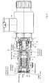
Fig. 1 ein direkt betätigtes Stromregelventil gemäß einem ersten bevorzugten Ausführungsbeispiel der Erfindung mit integrierter Druckwaage und Druckwaagekolben-Dämpfung. - In der
Fig. 1 ist ein vorzugsweise direkt betätigtes Stromregelventil gemäß dem bevorzugten Ausführungsbeispiel der Erfindung in cartridge-Bauweise dargestellt. Demzufolge hat das erfindungsgemäße Stromregelventil ein patronenförmiges Gehäuse in der Form einer Hülse, die an Ihrer äußeren Mantelfläche mit einer Anzahl von axial beabstandeten Radialstufen 2 ausgeformt ist. Die Hülse 1 hat an einem axialen Endabschnitt einen radial vorstehenden Anschlagsring 4, dem unmittelbar ein Außengewindeabschnitt 6 vorgeordnet ist, damit die Hülse 1 beispielsweise in einen nicht gezeigten Ventilblock eingeschraubt werden kann. - Auf der dem Anschlagring 4 gegenüberliegenden axialen Endseite der Hülse 1 ist ein Axialanschluss P vorzugsweise für das Anschließen einer (nicht gezeigten) Druckmittelzuführeinrichtung vorgesehen. An dieser axialen Endseite ist die Hülse 1 mit einer inneren Umfangsnut 8 ausgeformt, an die sich in einem geringen Axialabstand ein umlaufender innerer Radialabsatz mit geringerem Durchmesser anschließt. Zwischen diesem Radialabsatz 10 und der Umfangsnut 8 ist eine Abschlussscheibe 12 eingesetzt, die von einem Sicherungsring 14 (Federring) axial möglichst spielfrei gehalten wird, der in die Umfangsnut 8 eingeschnappt ist.
- Des Weiteren ist in die Hülse 1 ein hohler/hülsenförmiger Druckwagekolben 16 axial verschieblich eingesetzt, der einen axial sich erstreckenden Gleitabschnitt 16a hat, welcher unmittelbar mit der Hülse 1 an deren Innenwandung in Gleitkontakt steht. An dem zur Abschlussscheibe 12 zugewandten axialen Endabschnitt des Druckwagenkolbens 16 weist dieser einen radialen äußeren Rücksprung 16b auf, der sich ausgehend vom Gleitabschnitt 16a bis zu der der Abschlussscheibe 12 zugewandten Stirnseite des Druckwaagekolbens 16 erstreckt. In der Abschlussscheibe 12 ist eine Durchgangsbohrung oder Durchbruch ausgeformt, derart, dass der Druckwaagekolben 16 im Bereich seines äußeren radialen Rücksprungs 16a in die Abschlussscheibe 12 gleitend (zentral) eingeführt werden kann. Hierdurch bildet sich zwischen dem Druckwagenkolben 16, der inneren Hülsenwandung und der Abschlussscheibe 12 ein ringförmiger Raum 18 aus, der eine nachfolgend beschriebene Dämpfungskammer 18 definiert. Des Weiteren ist in der Abschlussscheibe 16 zumindest eine weitere dezentrale Durchgangsbohrung 20 mit vorbestimmtem (kleinem) Durchmesser ausgeformt, welche die Dämpfungskammer mit dem Axialanschluss P verbindet und eine nachfolgend noch beschriebene Drosseldüse definiert.
- Die Gehäusehülse 1 hat in einem axialen Mittenabschnitt zumindest eine radiale Durchgangsbohrung 22, die einen Auslassanschluss A des erfindungsgemäßen Ventils darstellt. Der Druckwaagekolben 16 hat dabei eine axiale Länge, die derart definiert ist, dass der Druckwaagekolben 16 in einer ersten zurückgezogenen Position (maximal zur Abschlussscheibe 12 beabstandet) die Radialbohrung 22 in der Gehäusehülse vollständig verschließt. In dieser Position hat die Dämpfungskammer 18 ein maximales Raumvolumen.
- Die innere axiale Stirnseite des Druckwaagekolbens 16 bildet dabei mit der Gehäusehülse 1 im Bereich der darin ausgeformten Radialbohrung 22 eine Regelblende R des Ventils.
- Der Druckwaagekolben 16 ist ferner mittels einer Vorspannfeder 24 in Richtung zur Abschlussscheibe 12 für ein Öffnen der Radialbohrung 22 in der Gehäusehülse 1 vorgespannt. Diese Vorspannfeder 24 ist hierfür in den hohlen Druckwaagekolben 16 eingesetzt und stützt sich hierfür an einem radial nach Innen vorstehenden Umfangsvorsprung 16c am Druckwaagekolben 16 axial ab. Ein gegengerichteter Federsitz wird ferner durch eine Führungshülse 26 gebildet, die an einem zur Abschlussscheibe 12 abgewandten Endabschnitt in den Druckwaagekolben 16 gleitend eingeführt ist und dabei gleichzeitig einen Axialanschlag für den Druckwaagekolben 16 zur Definition der ersten vorstehend beschriebenen Position des Druckwaagekolbens 16 bildet. Hierfür hat der Führungshülse 26 an einem Endabschnitt einen radial äußeren Absatzvorsprung 26a, der mit dem Druckwaagekolben 16 für einen Axialanschlag in Wirkeingriff bringbar ist. Die Führungshülse 26 hat des Weiteren zumindest an ihrem anderen Endabschnitt eine äußere Umfangsfläche 26b, die vorzugsweise dichtend mit der Gehäusehülse 1 an deren Innenwandung in Anlage ist. In einem axialen Mittenabschnitt 26c der Führungshülse 26 axial zwischen dem Druckwaagekolben 16 bzw. dem Absatzvorsprung 26a sowie der Anlagefläche 26b mit der Gehäusehülse 1 ist eine axial sich erstreckender umlaufender Ringraum 28 ausgebildet, welcher vom Druckwaagekolben 16 axial begrenzt wird. In diesen umlaufenden Ringraum 28 zwischen dem Druckwaagekolben 16 der Gehäusehülse 1 und der Führungshülse 26 mündet zumindest eine Radialbohrung 30 im Führungskolben 26 an einer axialen Stelle, die vom Druckwaagekolben 16 nicht überdeckt werden kann. Schließlich ist die Führungshülse 26 axial an seinem inneren, dem Druckwaagekolben 16 abgewandten Endabschnitt durch einen an der Gehäusehülse 1 sich abstützenden Endanschlag 32 gehalten.
- In der Führungshülse 26 ist von ihrer dem Druckwaagekolben 16 abgewandten Seite her eine Betätigungskolben 34 in Form einer Hülse gleitend sowie dichtend eingesetzt. Dieser Betätigungskolben 34 hat in einem Mittenabschnitt eine Anzahl von Radialbohrungen 36, die mit der zumindest einen Radialbohrung 30 in der Führungshülse 26 eine einstellbare Messblende M ausbilden. Das heißt, in Abhängigkeit von der axialen Relativposition zwischen dem Betätigungskolben 34 und der Führungshülse 26 wird die durch die jeweiligen Radialbohrungen 30, 36 sich ausbildende Messblende M in vorbestimmter Weise teilgeöffnet, wodurch der durch den radial äußeren Umfang der Führungshülse 26 sich ausbildende Ringraum einen Fluidzugang zu dem Axialanschluss P des Ventils erhält. Der Betätigungskolben 34 wird dabei in dem vorliegenden Ausführungsbeispiel gemäß der
Fig. 1 direkt gesteuert, d. h. vorzugsweise mittels eines elektromagnetischen Stellantriebs 38 in Axialrichtung betätigt, wobei der Betätigungskolben 34 zusätzlich mittels einer Stellfeder 40 in eine gemäß derFig. 1 dargestellte Schließposition vorgespannt ist, in welcher die durch die Radialbohrungen 30, 36 in dem Betätigungskolben 34 und der diese umgebenden Führungshülse 26 ausgebildete Messblende M vollständig geschlossen ist. - Schließlich ist an dem Druckwaagekolben 16 in einem axialen Abschnitt unmittelbar hinter dem Dämpfungsraum 18 mit einer Anzahl von Radialbohrungen 42 ausgebildet, welche in Abhängigkeit der Axialposition des Druckwaagekolbens 16 bezüglich der Gehäusehülse 1 mit einer weiteren Radialbohrung 44 in der Gehäusehülse 1 verbunden werden können, um hierdurch einen Bypasskreis T zu öffnen, wie dies nachfolgend noch beschrieben wird.
- Die Funktionsweise des vorstehend konstruktiv beschriebenen Stromregelventils mit integrierter Druckwaage und Dämpfungskammer wird nachfolgend genauer beschrieben:
- In der gemäß der
Fig. 1 dargestellten Schaltposition ist der Betätigungskolben 34 unbetätigt, d. h. der vorzugsweise elektromagnetische Stellantrieb 38 ist in einem entregten Zustand. In diesem Fall wird der Betätigungskolben 34 durch die Stellfeder 40 in eine gemäß derFig. 1 rechte Anschlagsposition gedrückt, in welcher die zwischen den Radialbohrungen 36 in dem Betätigungskolben 34 und der zumindest einen Radialbohrung 30 in der diese umgebenden Führungshülse 26 sich ausbildenden Messblende M völlig geschlossen ist. Demzufolge gelangt kein Druckmittel, welches über den Axialanschluss P des Ventils in den Innenraum des Druckwaagekolbens 16, der Führungshülse 26 sowie dem Betätigungskolben 34 gefördert wird, in dem an der radialen Außenseite der Führungshülse 26 sich ausbildenden Ringraum 28. In dieser Schaltposition wird folglich der Druckwaagekolben 16 lediglich durch die Vorspannfeder 24 in Richtung zur Abschlussscheibe 12 gedrückt, wobei sich ein über die (Drossel-)Bohrung 20 in der Abschlusshülse 12 aufbauende Gegendruck den Druckwaagekolben 16 gegen die Vorspannkraft der Vorspannfeder 24 in Richtung zum von der Führungshülse 26 ausgebildeten Axialanschlag 26a drückt. Das heißt, dass in dieser Schaltposition der Druckwaagekolben 16 die erste Axialposition einnimmt, in welcher die zwischen dem Druckwaagekolben 16 und der Gehäusehülse 1 ausgebildeten Regelblende R vollständig geschlossen und damit der Ausgangsanschluss A gesperrt wird. Des Weiteren wird in dieser Schaltposition eine Verbindung zwischen dem Axialanschluss P und dem Bypasskreis T geöffnet, sodass Druckmittel über das Stromregelventil gemäß dem bevorzugten Ausführungsbeispiel zirkulieren kann. - Wird nunmehr der vorzugsweise elektromagnetische Stellantrieb 38 betätigt, übt dieser eine axiale Stellkraft auf den Betätigungskolben 34, entgegen der Stellfederkraft aus, und verschiebt diesen in Axialrichtung zur Abschlussscheibe 12. Hierbei wird die zwischen der Führungshülse 26 und dem Betätigungskolben 34 ausgebildete Messblende M entsprechend dem eingestellten Stellwert des Betätigungskolben 34 geöffnet und somit ein gedrosselter Zugang zwischen dem Axialanschluss P des Ventils und dem zwischen der Führungshülse 26 und der Gehäusehülse 1 sich ausbildenden Ringraum 28 geschaffen. Der sich dadurch aufbauende Ringraumdruck bewirkt eine axiale Verschiebung des Druckwaagekolbens in Richtung Abschlussscheibe 12, wobei diese Verschiebebewegung durch ein gedrosseltes Abströmen von Druckmittel aus der Dämpfungskammer 18 über die Axialdrosselbohrung 20 (oder Ringspalt) gedämpft wird.
- Infolge der gedämpften Axialbewegung des Druckwaagekolbens 16 öffnet sich die zwischen dem Druckwaagekolben 16 und der Gehäusehülse 1 ausgebildeten Regelblende R, wodurch eine gedrosselte Öffnung zwischen dem Ringraum 28 und dem Ausgangsanschluss A des Ventils geschaffen wird. Gleichzeitig wird durch die axiale Bewegung des Druckwaagekolbens 16 die Verbindung zwischen dem Axialanschluss P und dem Bypasskreis T geschlossen. Daher kann nunmehr Druckmittel über den Axialanschluss P, die Messblende M, den Ringraum 28 sowie die Regelblende R in den Ausgangsanschluss A des Ventils strömen.
- Anschließend sei darauf hingewiesen, dass das Stromregelventil mit integrierter Druckwaage und Dämpfungskammer, auch so abgewandelt werden kann, indem die vorstehend beschriebene Direktansteuerung des Betätigungskolben 34 durch einen Vorsteuermechanismus ersetzt ist. In diesem Fall bestätigt der vorzugsweise elektromagnetischer Antrieb 38 ein Vorsteuerventil, über welches der Betätigungskolben 34 axial verstellbar ist.
-
- 1
- Gehäusehülse
- 2
- Radialstufen
- 4
- Anschlagring
- 6
- Außengewindeabschnitt
- P
- Axialanschluss
- 8
- innere Umfangsnut
- 10
- Radialabsatz
- 12
- Abschlussscheibe
- 14
- Sicherungsring
- 16
- Druckwaage-Kolben
- 16a
- Gleitabschnitt
- 16b
- radial äußerer Rücksprung
- 16c
- nach innen vorstehenden Umfangsvorsprung
- 18
- Dämpfungskammer
- 20
- Drosseldüse
- 22
- radiale Durchgangsbohrung in Gehäusehülse
- A
- Auslassanschluss
- R
- Regelblende
- 24
- Vorspannfeder
- 26
- Führungshülse
- 26a
- radial äußerer Absatzvorsprung
- 26b
- radial äußere Anlagefläche
- 26c
- radial zurückgesetzter äußerer Axial-Mitteabschnitt
- 28
- Ringraum
- 30
- Radialbohrung(en) in Führungshülse
- 32
- Endanschlag
- 34
- Betätigungskolben
- 36
- Radialbohrung(en) im Betätigungskolben
- M
- Messblende
- 38
- elektrischer Stellantrieb / Vorsteuermechanismus
- 40
- Stellfeder
- 42
- Radialbohrung(en) in Druckwaage-Kolben
- 44
- Radialbohrung(en) in Gehäusehülse 1
- T
- Bypass-Anschluss
Claims (12)
- Ventil mit einem Druckwaage-Kolben (16), der axialverschieblich in einem Ventilgehäuse (1) gelagert ist, dadurch gekennzeichnet, dass der Druckwaage-Kolben (16) zusammen mit dem Ventilgehäuse (1) eine Dämpfungskammer (18) zur Bewegungsdämpfung des Druckwaage-Kolbens (16) ausbilden.
- Ventil nach Anspruch 1, dadurch gekennzeichnet, dass die Dämpfungswirkung durch eine mit der Dämpfungskammer (18) fluidverbundene Drosselöffnung (20) eingestellt oder einstellbar ist.
- Ventil nach einem der vorstehenden Ansprüche, dadurch gekennzeichnet, dass die Dämpfungskammer (18) an einem axialen Endabschnitt des Druckwaage-Kolbens (16) zwischen dem Druckwaage-Kolben (16), dem Ventilgehäuse (1) und einer am Ventilgehäuse (1) dichtend fixierten axialen Abschlussscheibe (12) ausgebildet ist, in der der Druckwaage-Kolben (16) axial geführt ist.
- Ventil nach Anspruch 2 und 3, dadurch gekennzeichnet, dass die Drosselöffnung (20) durch einen Ringspalt zwischen der Abschlussscheibe (12) und dem Druckwaage-Kolben (16) und/oder zumindest eine Bohrung in der Abschlussscheibe (12) und/oder dem Ventilgehäuse (1) gebildet ist.
- Ventil nach einem der Ansprüche 3 und 4, dadurch gekennzeichnet, dass die Abschlussscheibe (12) durch einen Sicherungsring (14) gehalten ist, der vorzugsweise als Federring ausgebildet ist und in eine innere Umfangsnut (8) im Ventilgehäuse (1) formschlüssig eingreift.
- Ventil nach einem der vorstehenden Ansprüche 3-5, dadurch gekennzeichnet, dass der Druckwaage-Kolben (16) einen Gleitabschnitt (16a) hat, der mit dem Ventilgehäuse (1) in Gleitkontakt steht und der an dem einen axialen Endabschnitt des Druckwaage-Kolben (16) von einem radialen Rücksprung (16b) begrenzt ist, der in der Abschlussscheibe (12) gleitend aufgenommen ist und dabei die Dämpfungskammer (18) axial zwischen der Abschlussscheibe (12) und dem Gleitabschnitt (16a) des Druckwaage-Kolben (16) definiert.
- Ventil nach einem der vorstehenden Ansprüche 3 - 6 dadurch gekennzeichnet, dass an dem einen axialen Endabschnitt des Druckwaage-Kolben (16) ein Axialanschluss (P) des Ventils zur Druckmittelzufuhr ausgebildet ist, in den die Drosselöffnung (20) einmündet.
- Ventil nach einem der vorstehenden Ansprüche 3-7, dadurch gekennzeichnet, dass das Ventil ein Stromregelventil und der Ventilkolben (16) ein Druckwaagekolben ist.
- Ventil nach Anspruch 8, dadurch gekennzeichnet, dass der Druckwaagekolben (16) eine Gleithülse ist, die an ihrem anderen axialen Endabschnitt mit dem Ventilgehäuse eine Regelblende (R) der Druckwaage bildet, zum geregelten Öffnen eines Auslassanschlusses (A) des Ventils, wofür am Ventilgehäuse (1) zumindest eine vom Druckwaagekolben (16) verschließbare radiale Durchgangsbohrung (22) ausgebildet ist.
- Ventil nach Anspruch 9, gekennzeichnet durch eine Führungshülse (26), die in axialer Verlängerung zum Druckwaagekolben (16) sowohl in diesem als auch am Ventilgehäuse (1) gelagert ist und zwischen sich und dem Ventilgehäuse (1) einen den Druckwaagekolben (16) stirnseitig Druck-beaufschlagenden Ringraum (28) ausbildet.
- Ventil nach Anspruch 10, gekennzeichnet durch eine direkt- oder vorgesteuerte, hülsenförmigen Betätigungskoben (34), die axial verschieblich in der Führungshülse (26) geführt ist und mit dieser eine einstellbare Messblende (M) zur eingestellten Zufuhr an Druckmittel in den Ringraum (28) bildet.
- Ventil nach Anspruch 11, dadurch gekennzeichnet, dass die Messblende (M) durch eine Anzahl von Radialbohrungen (36) in dem Betätigungskolben (34) und diese in Abhängigkeit der axialen Relativlage überlappenden Radialbohrungen (30) in der Führungshülse (26) definiert ist.
Applications Claiming Priority (1)
| Application Number | Priority Date | Filing Date | Title |
|---|---|---|---|
| DE102010005524A DE102010005524A1 (de) | 2010-01-23 | 2010-01-23 | Stromregelventil mit Dämpfungskammer |
Publications (2)
| Publication Number | Publication Date |
|---|---|
| EP2348376A1 true EP2348376A1 (de) | 2011-07-27 |
| EP2348376B1 EP2348376B1 (de) | 2013-05-29 |
Family
ID=43646470
Family Applications (1)
| Application Number | Title | Priority Date | Filing Date |
|---|---|---|---|
| EP20110000251 Active EP2348376B1 (de) | 2010-01-23 | 2011-01-14 | Stromregelventil mit Dämpfungskammer |
Country Status (3)
| Country | Link |
|---|---|
| US (1) | US8662097B2 (de) |
| EP (1) | EP2348376B1 (de) |
| DE (1) | DE102010005524A1 (de) |
Families Citing this family (9)
| Publication number | Priority date | Publication date | Assignee | Title |
|---|---|---|---|---|
| JP5453918B2 (ja) * | 2009-05-18 | 2014-03-26 | トヨタ自動車株式会社 | 流量制御弁 |
| DE102009049548A1 (de) * | 2009-10-16 | 2011-04-21 | Hydac Fluidtechnik Gmbh | Ventilanordnung |
| US9091355B2 (en) * | 2013-03-15 | 2015-07-28 | David Albrecht | Main stage in-line pressure control cartridge with optional reverse flow function |
| US9518670B2 (en) * | 2013-03-15 | 2016-12-13 | David E Albrecht | Main stage in-line pressure control cartridge with stepped retainer collar |
| US9777865B2 (en) * | 2014-04-15 | 2017-10-03 | Fema Corporation Of Michigan | Balanced electronically controlled pressure regulating valve |
| CN107965488A (zh) * | 2017-11-25 | 2018-04-27 | 宁波文泽机电技术开发有限公司 | 一种插装式比例流量阀 |
| CN107965490A (zh) * | 2017-11-25 | 2018-04-27 | 宁波文泽机电技术开发有限公司 | 比例调速阀 |
| CN107763000A (zh) * | 2017-11-25 | 2018-03-06 | 宁波文泽机电技术开发有限公司 | 反比例流量阀 |
| DE102018122437A1 (de) * | 2018-09-13 | 2020-03-19 | Eto Magnetic Gmbh | Proportionalventil |
Citations (4)
| Publication number | Priority date | Publication date | Assignee | Title |
|---|---|---|---|---|
| US3724485A (en) * | 1971-05-12 | 1973-04-03 | Servo Labs Inc | Flow controller |
| WO1986000731A1 (en) * | 1984-07-06 | 1986-01-30 | Brunswick Valve And Control, Inc. | Liquid flow controller having pressure balanced piston for delivering constant flow |
| US6966329B2 (en) | 2003-01-27 | 2005-11-22 | Hydraforce, Inc. | Proportional pilot-operated flow control valve |
| US20080230729A1 (en) * | 2005-10-20 | 2008-09-25 | Dominique Costaz | Valve With Cushioned Opening System |
Family Cites Families (11)
| Publication number | Priority date | Publication date | Assignee | Title |
|---|---|---|---|---|
| US4576200A (en) * | 1985-03-26 | 1986-03-18 | Applied Power Inc. | Hydraulic pressure reducing control valve |
| US4630640A (en) * | 1985-06-10 | 1986-12-23 | Sun Hydraulics Corp. | Pressure compensated restrictive flow regulator cartridge |
| US5184644A (en) * | 1991-05-30 | 1993-02-09 | Coltec Industries Inc. | Solenoid operated pressure regulating valve |
| US5836335A (en) * | 1991-08-19 | 1998-11-17 | Fluid Power Industries, Inc. | Proportional pressure control valve |
| DE4129828C1 (de) * | 1991-09-07 | 1993-04-29 | Mercedes-Benz Aktiengesellschaft, 7000 Stuttgart, De | |
| US5639066A (en) * | 1995-06-15 | 1997-06-17 | Applied Power Inc. | Bidirectional flow control valve |
| US6029703A (en) * | 1998-12-18 | 2000-02-29 | Borg-Warner Automotive, Inc. | Pressure solenoid control valve with flux shunt |
| DE10037793B4 (de) * | 2000-08-03 | 2007-05-24 | Hydraulik-Ring Gmbh | Magnetventil, insbesondere Druckregelventil |
| US6615869B2 (en) * | 2001-03-26 | 2003-09-09 | Denso Corporation | Solenoid valve |
| JP4030491B2 (ja) * | 2003-10-15 | 2008-01-09 | 株式会社ケーヒン | 常開型油圧制御弁 |
| US7717128B2 (en) * | 2005-11-07 | 2010-05-18 | Arpad Matyas Pataki | Pressure balanced three-way valve for motion control |
-
2010
- 2010-01-23 DE DE102010005524A patent/DE102010005524A1/de not_active Withdrawn
-
2011
- 2011-01-14 EP EP20110000251 patent/EP2348376B1/de active Active
- 2011-01-20 US US13/010,645 patent/US8662097B2/en active Active
Patent Citations (4)
| Publication number | Priority date | Publication date | Assignee | Title |
|---|---|---|---|---|
| US3724485A (en) * | 1971-05-12 | 1973-04-03 | Servo Labs Inc | Flow controller |
| WO1986000731A1 (en) * | 1984-07-06 | 1986-01-30 | Brunswick Valve And Control, Inc. | Liquid flow controller having pressure balanced piston for delivering constant flow |
| US6966329B2 (en) | 2003-01-27 | 2005-11-22 | Hydraforce, Inc. | Proportional pilot-operated flow control valve |
| US20080230729A1 (en) * | 2005-10-20 | 2008-09-25 | Dominique Costaz | Valve With Cushioned Opening System |
Also Published As
| Publication number | Publication date |
|---|---|
| DE102010005524A1 (de) | 2011-07-28 |
| US8662097B2 (en) | 2014-03-04 |
| US20110197979A1 (en) | 2011-08-18 |
| EP2348376B1 (de) | 2013-05-29 |
Similar Documents
| Publication | Publication Date | Title |
|---|---|---|
| EP2348376B1 (de) | Stromregelventil mit Dämpfungskammer | |
| EP2382520B1 (de) | Proportional-druckregelventil und seine verwendung für hydraulisch betätigbare kupplungen | |
| EP1781953B1 (de) | Pilotventil, insbesondere für servoventile | |
| EP1629336B1 (de) | Ventil | |
| DE102007058620B3 (de) | Kolbenschieberventil | |
| EP1826649A2 (de) | Wege- oder Stromventil | |
| DE102009019554B3 (de) | Proportional-Drosselventil | |
| EP1996821B1 (de) | Ludv-ventilanordnung | |
| EP2558758B1 (de) | Stromregelventil | |
| EP3295065B1 (de) | Ventil, insbesondere proportional-druckregelventil | |
| EP3230618B1 (de) | Verstellbare dämpfventileinrichtung | |
| EP2669528A2 (de) | Hydrostatische Ventilanordnung und hydrostatische Steueranordnung mit der Ventilanordnung | |
| EP2880315B1 (de) | Ventil, insbesondere vorgesteuertes proportional-wegesitzventil | |
| DE3015830A1 (de) | Sperrvorrichtung fuer kolben-zylinder-einheiten | |
| DE102012015356A1 (de) | Ventil, insbesondere vorgesteuertes Proportional-Wegesitzventil | |
| DE102014007475B4 (de) | Ventilanordnung zur gesteuerten Druckentlastung fluidgefüllter Leitungen unter erhöhten Sicherheitsanforderungen | |
| EP3392505B1 (de) | Mischventilanordnung für ein hydraulisches system, sowie ölkühlsystem und kompressoranlage mit dieser | |
| EP1452744B1 (de) | Hydraulische Steueranordnung | |
| EP1703185A1 (de) | Coaxialventil | |
| WO2005106611A1 (de) | Stromregelventil | |
| DE102008000296A1 (de) | Elektromagnetisch betätigbares Sitzventil | |
| DE102011117086A1 (de) | UND-Ventil | |
| DE10245836B4 (de) | LS-Wegeventilanordnung | |
| WO2003091576A1 (de) | Ls-wegeventilanordnung | |
| DE19960885B4 (de) | Stromregelventil |
Legal Events
| Date | Code | Title | Description |
|---|---|---|---|
| PUAI | Public reference made under article 153(3) epc to a published international application that has entered the european phase |
Free format text: ORIGINAL CODE: 0009012 |
|
| AK | Designated contracting states |
Kind code of ref document: A1 Designated state(s): AL AT BE BG CH CY CZ DE DK EE ES FI FR GB GR HR HU IE IS IT LI LT LU LV MC MK MT NL NO PL PT RO RS SE SI SK SM TR |
|
| AX | Request for extension of the european patent |
Extension state: BA ME |
|
| 17P | Request for examination filed |
Effective date: 20120127 |
|
| 17Q | First examination report despatched |
Effective date: 20120330 |
|
| GRAP | Despatch of communication of intention to grant a patent |
Free format text: ORIGINAL CODE: EPIDOSNIGR1 |
|
| GRAS | Grant fee paid |
Free format text: ORIGINAL CODE: EPIDOSNIGR3 |
|
| GRAA | (expected) grant |
Free format text: ORIGINAL CODE: 0009210 |
|
| AK | Designated contracting states |
Kind code of ref document: B1 Designated state(s): AL AT BE BG CH CY CZ DE DK EE ES FI FR GB GR HR HU IE IS IT LI LT LU LV MC MK MT NL NO PL PT RO RS SE SI SK SM TR |
|
| REG | Reference to a national code |
Ref country code: GB Ref legal event code: FG4D Free format text: NOT ENGLISH |
|
| REG | Reference to a national code |
Ref country code: CH Ref legal event code: EP |
|
| REG | Reference to a national code |
Ref country code: AT Ref legal event code: REF Ref document number: 614780 Country of ref document: AT Kind code of ref document: T Effective date: 20130615 |
|
| REG | Reference to a national code |
Ref country code: IE Ref legal event code: FG4D Free format text: LANGUAGE OF EP DOCUMENT: GERMAN |
|
| REG | Reference to a national code |
Ref country code: DE Ref legal event code: R096 Ref document number: 502011000775 Country of ref document: DE Effective date: 20130725 |
|
| REG | Reference to a national code |
Ref country code: LT Ref legal event code: MG4D |
|
| PG25 | Lapsed in a contracting state [announced via postgrant information from national office to epo] |
Ref country code: IS Free format text: LAPSE BECAUSE OF FAILURE TO SUBMIT A TRANSLATION OF THE DESCRIPTION OR TO PAY THE FEE WITHIN THE PRESCRIBED TIME-LIMIT Effective date: 20130929 Ref country code: NO Free format text: LAPSE BECAUSE OF FAILURE TO SUBMIT A TRANSLATION OF THE DESCRIPTION OR TO PAY THE FEE WITHIN THE PRESCRIBED TIME-LIMIT Effective date: 20130829 Ref country code: ES Free format text: LAPSE BECAUSE OF FAILURE TO SUBMIT A TRANSLATION OF THE DESCRIPTION OR TO PAY THE FEE WITHIN THE PRESCRIBED TIME-LIMIT Effective date: 20130909 Ref country code: FI Free format text: LAPSE BECAUSE OF FAILURE TO SUBMIT A TRANSLATION OF THE DESCRIPTION OR TO PAY THE FEE WITHIN THE PRESCRIBED TIME-LIMIT Effective date: 20130529 Ref country code: PT Free format text: LAPSE BECAUSE OF FAILURE TO SUBMIT A TRANSLATION OF THE DESCRIPTION OR TO PAY THE FEE WITHIN THE PRESCRIBED TIME-LIMIT Effective date: 20130930 Ref country code: SE Free format text: LAPSE BECAUSE OF FAILURE TO SUBMIT A TRANSLATION OF THE DESCRIPTION OR TO PAY THE FEE WITHIN THE PRESCRIBED TIME-LIMIT Effective date: 20130529 Ref country code: LT Free format text: LAPSE BECAUSE OF FAILURE TO SUBMIT A TRANSLATION OF THE DESCRIPTION OR TO PAY THE FEE WITHIN THE PRESCRIBED TIME-LIMIT Effective date: 20130529 Ref country code: GR Free format text: LAPSE BECAUSE OF FAILURE TO SUBMIT A TRANSLATION OF THE DESCRIPTION OR TO PAY THE FEE WITHIN THE PRESCRIBED TIME-LIMIT Effective date: 20130830 Ref country code: SI Free format text: LAPSE BECAUSE OF FAILURE TO SUBMIT A TRANSLATION OF THE DESCRIPTION OR TO PAY THE FEE WITHIN THE PRESCRIBED TIME-LIMIT Effective date: 20130529 |
|
| REG | Reference to a national code |
Ref country code: NL Ref legal event code: VDEP Effective date: 20130529 |
|
| PG25 | Lapsed in a contracting state [announced via postgrant information from national office to epo] |
Ref country code: HR Free format text: LAPSE BECAUSE OF FAILURE TO SUBMIT A TRANSLATION OF THE DESCRIPTION OR TO PAY THE FEE WITHIN THE PRESCRIBED TIME-LIMIT Effective date: 20130529 Ref country code: PL Free format text: LAPSE BECAUSE OF FAILURE TO SUBMIT A TRANSLATION OF THE DESCRIPTION OR TO PAY THE FEE WITHIN THE PRESCRIBED TIME-LIMIT Effective date: 20130529 Ref country code: RS Free format text: LAPSE BECAUSE OF FAILURE TO SUBMIT A TRANSLATION OF THE DESCRIPTION OR TO PAY THE FEE WITHIN THE PRESCRIBED TIME-LIMIT Effective date: 20130529 Ref country code: BG Free format text: LAPSE BECAUSE OF FAILURE TO SUBMIT A TRANSLATION OF THE DESCRIPTION OR TO PAY THE FEE WITHIN THE PRESCRIBED TIME-LIMIT Effective date: 20130829 |
|
| PG25 | Lapsed in a contracting state [announced via postgrant information from national office to epo] |
Ref country code: LV Free format text: LAPSE BECAUSE OF FAILURE TO SUBMIT A TRANSLATION OF THE DESCRIPTION OR TO PAY THE FEE WITHIN THE PRESCRIBED TIME-LIMIT Effective date: 20130529 |
|
| PG25 | Lapsed in a contracting state [announced via postgrant information from national office to epo] |
Ref country code: EE Free format text: LAPSE BECAUSE OF FAILURE TO SUBMIT A TRANSLATION OF THE DESCRIPTION OR TO PAY THE FEE WITHIN THE PRESCRIBED TIME-LIMIT Effective date: 20130529 Ref country code: SK Free format text: LAPSE BECAUSE OF FAILURE TO SUBMIT A TRANSLATION OF THE DESCRIPTION OR TO PAY THE FEE WITHIN THE PRESCRIBED TIME-LIMIT Effective date: 20130529 Ref country code: CZ Free format text: LAPSE BECAUSE OF FAILURE TO SUBMIT A TRANSLATION OF THE DESCRIPTION OR TO PAY THE FEE WITHIN THE PRESCRIBED TIME-LIMIT Effective date: 20130529 Ref country code: DK Free format text: LAPSE BECAUSE OF FAILURE TO SUBMIT A TRANSLATION OF THE DESCRIPTION OR TO PAY THE FEE WITHIN THE PRESCRIBED TIME-LIMIT Effective date: 20130529 |
|
| PG25 | Lapsed in a contracting state [announced via postgrant information from national office to epo] |
Ref country code: NL Free format text: LAPSE BECAUSE OF FAILURE TO SUBMIT A TRANSLATION OF THE DESCRIPTION OR TO PAY THE FEE WITHIN THE PRESCRIBED TIME-LIMIT Effective date: 20130529 Ref country code: RO Free format text: LAPSE BECAUSE OF FAILURE TO SUBMIT A TRANSLATION OF THE DESCRIPTION OR TO PAY THE FEE WITHIN THE PRESCRIBED TIME-LIMIT Effective date: 20130529 |
|
| PLBE | No opposition filed within time limit |
Free format text: ORIGINAL CODE: 0009261 |
|
| STAA | Information on the status of an ep patent application or granted ep patent |
Free format text: STATUS: NO OPPOSITION FILED WITHIN TIME LIMIT |
|
| 26N | No opposition filed |
Effective date: 20140303 |
|
| REG | Reference to a national code |
Ref country code: DE Ref legal event code: R097 Ref document number: 502011000775 Country of ref document: DE Effective date: 20140303 |
|
| BERE | Be: lapsed |
Owner name: ROBERT BOSCH G.M.B.H. Effective date: 20140131 |
|
| PG25 | Lapsed in a contracting state [announced via postgrant information from national office to epo] |
Ref country code: LU Free format text: LAPSE BECAUSE OF FAILURE TO SUBMIT A TRANSLATION OF THE DESCRIPTION OR TO PAY THE FEE WITHIN THE PRESCRIBED TIME-LIMIT Effective date: 20140114 |
|
| REG | Reference to a national code |
Ref country code: CH Ref legal event code: PL |
|
| PG25 | Lapsed in a contracting state [announced via postgrant information from national office to epo] |
Ref country code: CH Free format text: LAPSE BECAUSE OF NON-PAYMENT OF DUE FEES Effective date: 20140131 Ref country code: LI Free format text: LAPSE BECAUSE OF NON-PAYMENT OF DUE FEES Effective date: 20140131 |
|
| REG | Reference to a national code |
Ref country code: FR Ref legal event code: ST Effective date: 20140930 |
|
| REG | Reference to a national code |
Ref country code: IE Ref legal event code: MM4A |
|
| PG25 | Lapsed in a contracting state [announced via postgrant information from national office to epo] |
Ref country code: FR Free format text: LAPSE BECAUSE OF NON-PAYMENT OF DUE FEES Effective date: 20140131 |
|
| PG25 | Lapsed in a contracting state [announced via postgrant information from national office to epo] |
Ref country code: BE Free format text: LAPSE BECAUSE OF NON-PAYMENT OF DUE FEES Effective date: 20140131 Ref country code: IE Free format text: LAPSE BECAUSE OF NON-PAYMENT OF DUE FEES Effective date: 20140114 |
|
| PG25 | Lapsed in a contracting state [announced via postgrant information from national office to epo] |
Ref country code: MC Free format text: LAPSE BECAUSE OF FAILURE TO SUBMIT A TRANSLATION OF THE DESCRIPTION OR TO PAY THE FEE WITHIN THE PRESCRIBED TIME-LIMIT Effective date: 20130529 |
|
| PG25 | Lapsed in a contracting state [announced via postgrant information from national office to epo] |
Ref country code: MT Free format text: LAPSE BECAUSE OF FAILURE TO SUBMIT A TRANSLATION OF THE DESCRIPTION OR TO PAY THE FEE WITHIN THE PRESCRIBED TIME-LIMIT Effective date: 20130529 |
|
| PG25 | Lapsed in a contracting state [announced via postgrant information from national office to epo] |
Ref country code: SM Free format text: LAPSE BECAUSE OF FAILURE TO SUBMIT A TRANSLATION OF THE DESCRIPTION OR TO PAY THE FEE WITHIN THE PRESCRIBED TIME-LIMIT Effective date: 20130529 |
|
| PG25 | Lapsed in a contracting state [announced via postgrant information from national office to epo] |
Ref country code: CY Free format text: LAPSE BECAUSE OF FAILURE TO SUBMIT A TRANSLATION OF THE DESCRIPTION OR TO PAY THE FEE WITHIN THE PRESCRIBED TIME-LIMIT Effective date: 20130529 |
|
| PG25 | Lapsed in a contracting state [announced via postgrant information from national office to epo] |
Ref country code: TR Free format text: LAPSE BECAUSE OF FAILURE TO SUBMIT A TRANSLATION OF THE DESCRIPTION OR TO PAY THE FEE WITHIN THE PRESCRIBED TIME-LIMIT Effective date: 20130529 Ref country code: HU Free format text: LAPSE BECAUSE OF FAILURE TO SUBMIT A TRANSLATION OF THE DESCRIPTION OR TO PAY THE FEE WITHIN THE PRESCRIBED TIME-LIMIT; INVALID AB INITIO Effective date: 20110114 |
|
| REG | Reference to a national code |
Ref country code: AT Ref legal event code: MM01 Ref document number: 614780 Country of ref document: AT Kind code of ref document: T Effective date: 20160114 |
|
| PG25 | Lapsed in a contracting state [announced via postgrant information from national office to epo] |
Ref country code: AT Free format text: LAPSE BECAUSE OF NON-PAYMENT OF DUE FEES Effective date: 20160114 |
|
| PG25 | Lapsed in a contracting state [announced via postgrant information from national office to epo] |
Ref country code: MK Free format text: LAPSE BECAUSE OF FAILURE TO SUBMIT A TRANSLATION OF THE DESCRIPTION OR TO PAY THE FEE WITHIN THE PRESCRIBED TIME-LIMIT Effective date: 20130529 |
|
| PG25 | Lapsed in a contracting state [announced via postgrant information from national office to epo] |
Ref country code: AL Free format text: LAPSE BECAUSE OF FAILURE TO SUBMIT A TRANSLATION OF THE DESCRIPTION OR TO PAY THE FEE WITHIN THE PRESCRIBED TIME-LIMIT Effective date: 20130529 |
|
| PGFP | Annual fee paid to national office [announced via postgrant information from national office to epo] |
Ref country code: IT Payment date: 20230131 Year of fee payment: 13 |
|
| PGFP | Annual fee paid to national office [announced via postgrant information from national office to epo] |
Ref country code: DE Payment date: 20240322 Year of fee payment: 14 Ref country code: GB Payment date: 20240117 Year of fee payment: 14 |