EP2880315B1 - Ventil, insbesondere vorgesteuertes proportional-wegesitzventil - Google Patents
Ventil, insbesondere vorgesteuertes proportional-wegesitzventil Download PDFInfo
- Publication number
- EP2880315B1 EP2880315B1 EP13739146.2A EP13739146A EP2880315B1 EP 2880315 B1 EP2880315 B1 EP 2880315B1 EP 13739146 A EP13739146 A EP 13739146A EP 2880315 B1 EP2880315 B1 EP 2880315B1
- Authority
- EP
- European Patent Office
- Prior art keywords
- valve
- control
- pilot
- piston
- aperture
- Prior art date
- Legal status (The legal status is an assumption and is not a legal conclusion. Google has not performed a legal analysis and makes no representation as to the accuracy of the status listed.)
- Active
Links
- 239000012530 fluid Substances 0.000 claims description 55
- 230000001419 dependent effect Effects 0.000 claims description 6
- 230000001105 regulatory effect Effects 0.000 description 4
- 238000004519 manufacturing process Methods 0.000 description 3
- 238000010276 construction Methods 0.000 description 2
- 238000001914 filtration Methods 0.000 description 2
- 230000010354 integration Effects 0.000 description 2
- 230000007935 neutral effect Effects 0.000 description 2
- 239000002245 particle Substances 0.000 description 2
- 230000002411 adverse Effects 0.000 description 1
- 230000000903 blocking effect Effects 0.000 description 1
- 238000006073 displacement reaction Methods 0.000 description 1
- 230000000694 effects Effects 0.000 description 1
- 238000009434 installation Methods 0.000 description 1
- 238000007789 sealing Methods 0.000 description 1
- 230000007704 transition Effects 0.000 description 1
- 230000003313 weakening effect Effects 0.000 description 1
Images
Classifications
-
- F—MECHANICAL ENGINEERING; LIGHTING; HEATING; WEAPONS; BLASTING
- F16—ENGINEERING ELEMENTS AND UNITS; GENERAL MEASURES FOR PRODUCING AND MAINTAINING EFFECTIVE FUNCTIONING OF MACHINES OR INSTALLATIONS; THERMAL INSULATION IN GENERAL
- F16K—VALVES; TAPS; COCKS; ACTUATING-FLOATS; DEVICES FOR VENTING OR AERATING
- F16K1/00—Lift valves or globe valves, i.e. cut-off apparatus with closure members having at least a component of their opening and closing motion perpendicular to the closing faces
- F16K1/32—Details
- F16K1/52—Means for additional adjustment of the rate of flow
- F16K1/526—Means for additional adjustment of the rate of flow for limiting the maximum flow rate, using a second valve
-
- F—MECHANICAL ENGINEERING; LIGHTING; HEATING; WEAPONS; BLASTING
- F15—FLUID-PRESSURE ACTUATORS; HYDRAULICS OR PNEUMATICS IN GENERAL
- F15B—SYSTEMS ACTING BY MEANS OF FLUIDS IN GENERAL; FLUID-PRESSURE ACTUATORS, e.g. SERVOMOTORS; DETAILS OF FLUID-PRESSURE SYSTEMS, NOT OTHERWISE PROVIDED FOR
- F15B13/00—Details of servomotor systems ; Valves for servomotor systems
- F15B13/01—Locking-valves or other detent i.e. load-holding devices
- F15B13/015—Locking-valves or other detent i.e. load-holding devices using an enclosed pilot flow valve
-
- F—MECHANICAL ENGINEERING; LIGHTING; HEATING; WEAPONS; BLASTING
- F16—ENGINEERING ELEMENTS AND UNITS; GENERAL MEASURES FOR PRODUCING AND MAINTAINING EFFECTIVE FUNCTIONING OF MACHINES OR INSTALLATIONS; THERMAL INSULATION IN GENERAL
- F16K—VALVES; TAPS; COCKS; ACTUATING-FLOATS; DEVICES FOR VENTING OR AERATING
- F16K21/00—Fluid-delivery valves, e.g. self-closing valves
- F16K21/04—Self-closing valves, i.e. closing automatically after operation
-
- F—MECHANICAL ENGINEERING; LIGHTING; HEATING; WEAPONS; BLASTING
- F16—ENGINEERING ELEMENTS AND UNITS; GENERAL MEASURES FOR PRODUCING AND MAINTAINING EFFECTIVE FUNCTIONING OF MACHINES OR INSTALLATIONS; THERMAL INSULATION IN GENERAL
- F16K—VALVES; TAPS; COCKS; ACTUATING-FLOATS; DEVICES FOR VENTING OR AERATING
- F16K31/00—Actuating devices; Operating means; Releasing devices
- F16K31/12—Actuating devices; Operating means; Releasing devices actuated by fluid
- F16K31/122—Actuating devices; Operating means; Releasing devices actuated by fluid the fluid acting on a piston
-
- F—MECHANICAL ENGINEERING; LIGHTING; HEATING; WEAPONS; BLASTING
- F16—ENGINEERING ELEMENTS AND UNITS; GENERAL MEASURES FOR PRODUCING AND MAINTAINING EFFECTIVE FUNCTIONING OF MACHINES OR INSTALLATIONS; THERMAL INSULATION IN GENERAL
- F16K—VALVES; TAPS; COCKS; ACTUATING-FLOATS; DEVICES FOR VENTING OR AERATING
- F16K31/00—Actuating devices; Operating means; Releasing devices
- F16K31/12—Actuating devices; Operating means; Releasing devices actuated by fluid
- F16K31/36—Actuating devices; Operating means; Releasing devices actuated by fluid in which fluid from the circuit is constantly supplied to the fluid motor
- F16K31/40—Actuating devices; Operating means; Releasing devices actuated by fluid in which fluid from the circuit is constantly supplied to the fluid motor with electrically-actuated member in the discharge of the motor
- F16K31/406—Actuating devices; Operating means; Releasing devices actuated by fluid in which fluid from the circuit is constantly supplied to the fluid motor with electrically-actuated member in the discharge of the motor acting on a piston
- F16K31/408—Actuating devices; Operating means; Releasing devices actuated by fluid in which fluid from the circuit is constantly supplied to the fluid motor with electrically-actuated member in the discharge of the motor acting on a piston the discharge being effected through the piston and being blockable by an electrically-actuated member making contact with the piston
-
- Y—GENERAL TAGGING OF NEW TECHNOLOGICAL DEVELOPMENTS; GENERAL TAGGING OF CROSS-SECTIONAL TECHNOLOGIES SPANNING OVER SEVERAL SECTIONS OF THE IPC; TECHNICAL SUBJECTS COVERED BY FORMER USPC CROSS-REFERENCE ART COLLECTIONS [XRACs] AND DIGESTS
- Y10—TECHNICAL SUBJECTS COVERED BY FORMER USPC
- Y10T—TECHNICAL SUBJECTS COVERED BY FORMER US CLASSIFICATION
- Y10T137/00—Fluid handling
- Y10T137/7722—Line condition change responsive valves
- Y10T137/7754—Line flow effect assisted
- Y10T137/7755—Reactor surface normal to flow
Definitions
- the invention relates to a valve, in particular a pilot operated proportional directional seat valve, having the features in the preamble of claim 1.
- the proportional load lowering of forks on forklifts is often caused by seat valves with a constant opening behavior.
- the poppet valves can be directly operated or pilot operated.
- the use of poppet valves is particularly necessary because of the forklift manufacturers a so-called "stacker-proof" load behavior is required, which allows only very small leaks. By avoiding leaks in the hydraulic circuit, it is ensured that the forks can not fall down with or without loading, which would be a safety problem.
- a load-independent maximum volume flow limitation is adopted in known solutions of a connected in series with the other components of the hydraulic circuit constant volumetric flow controller. In this way, the requirement is met that a maximum lowering speed of a fork may not be exceeded regardless of the applied load pressure.
- the well-known control devices are disadvantageous in that when lowering the fork without load only the weight of the moving parts, especially in the form of Load fork, available on the mast to promote the hydraulic fluid from the working cylinder (plunger cylinder) back to the tank as part of the hydraulic circuit.
- the pressure at the cylinder may drop to values ⁇ 10 bar. The more components that have to be flowed through when lowering, the lower the volume flow will be.
- the known constant volume flow controller is a particularly high hurdle, because its inlet orifice must be chosen so small that a control pressure difference of at least 7 bar can be set. Smaller control pressures would lead to unstable behavior in the hydraulic circuit of the work equipment and can not be tolerated for safety reasons. Moreover, even with small control pressure differences, there must be no significant drop in sinking speed.
- the use of a maximum volumetric flow limitation has the additional disadvantage that the transition from the maximum volumetric flow limitation back into the proportional characteristic an adverse return occurs, which manifests itself in a discontinuous movement of a fork, which may represent another security problem.
- a series-connected current regulator causes a considerable pressure loss, which slows down the lowering of the load.
- the DE 199 55 522 A1 describes a valve, in particular pilot-operated proportional directional seat valve, comprising a valve housing having a fluid inlet and a fluid outlet, wherein the fluid flow between the fluid inlet and fluid outlet is regulated by a master piston, wherein on a rear side of the main piston, a pilot valve chamber with a pilot valve closing member movable by an actuator is provided, with which the fluid flow between the pilot valve chamber and the fluid outlet is regulated, wherein between the fluid inlet and the pilot valve chamber, a single inlet orifice is arranged, wherein the opening cross-section of the inlet orifice can be reduced by a control.
- a generic proportional directional seat valve is off DE 197 55 120 A1 known.
- the invention is therefore based on the object, a valve, in particular a pilot-operated proportional directional seat valve, show that is substantially leak-free, the lowering speed is independent of the upcoming load pressure, which operates at less than 10 bar pressure difference without significant sinking rate loss, which is also inexpensive and that takes up little space.
- valve in particular a pilot-operated proportional directional seat valve, having the features of claim 1.
- Advantageous embodiments of the valve will become apparent from the dependent claims.
- the inlet aperture has a plurality of aperture bores and that the opening cross section of at least one of the aperture bores can be reduced by the control element.
- the core idea of the invention is to integrate a current regulator in the valve. According to the invention, therefore, the opening cross section of the inlet aperture can be reduced by a control element.
- the reduced inlet cross-section causes the pressure in the pilot valve chamber to drop.
- the current control function is enabled.
- this solution saves an additional constant-volume flow controller connected in series or a pressure scale also connected in series. This results in lower manufacturing costs and a significantly reduced required space.
- the opening stroke of the main piston dependent on the differential pressure of the valve.
- a flow control function is possible in which an inlet orifice plate works alone without additional flow control edge.
- a differently sized diaphragm cross section must be used, depending on the differential pressure be opened.
- the load-dependent, variable opening cross section of the inlet orifice plate is a prerequisite for a load-independent volume flow through the valve.
- control is associated with the pilot valve closing member.
- control may be formed as a radial projection on the pilot valve closing member. Consequently, can be changed by an axial or rotary movement of the pilot valve closing member of the opening cross-section of the inlet aperture. Thus, no separate control device for the control must be provided.
- control is designed as a collar on the pilot valve closing member, wherein the collar has at least one pressure relief hole.
- a collar is a circumferential projection or flange on the pilot valve closure member.
- the aperture holes also preferably have the same diameter.
- the diaphragm bores can also have different diameters in order to additionally adapt the regulating behavior of the valve to the different load pressures involved and to give the control a characteristic deviating from the linearity.
- the diaphragm bores are arranged axially and / or circumferentially offset from one another in the main piston.
- This arrangement of the aperture bores additionally facilitates the reduction of the opening cross-section with the aid of the pilot valve closing member.
- the pilot valve closing member By the axial displacement of the pilot valve closing member relative to the main piston
- one or more aperture bores lying one behind the other in the axial direction can be closed.
- Over the circumference distributed aperture holes are about easier to manufacture, since the aperture holes have sections with different diameters.
- overlapping diaphragm bores or weakenings of the wall of the main piston are avoided by a plurality of concentrically arranged diaphragm bores.
- a slit diaphragm is provided between the fluid inlet and the inlet orifice, which slit is preferably designed in the form of an annular gap between the valve housing and the main valve piston.
- the slit diaphragm has a filtration function. It is intended to prevent particles of the fluid from entering the downstream units of the pilot valve. This can lead to blockages of the pilot valve and thus the failure of the valve as a whole.
- a maximum volume flow regulator is provided in the main piston in a sequence between the pilot control valve chamber and the fluid outlet.
- the maximum volume flow controller By the maximum volume flow controller, the flow of the expiring pilot fluid can be advantageously set independent of the load. In this way, the pressure in the pilot valve chamber is increased, so that the opening stroke of the main piston is reduced load pressure independent.
- the valve opens at a high load pressure, for example due to a high load on a fork of a forklift lower. The sinking speed of the fork is thus advantageously reduced.
- the integration of the maximum volume flow controller in the main piston virtually no additional space is required. Thus, compared to the solutions of the prior art with downstream control elements results in a considerable savings in space.
- the maximum volumetric flow controller preferably has a control piston, which is acted upon by a pressure on the front of the pilot chamber and on a rear side of a spring on a front side.
- the control piston can be acted upon by the pressure in the spring chamber (this is the pressure reduced by means of the inlet orifice).
- a fluid passage can be provided in the control piston, and control edges of the maximum volume flow regulator can be formed by bores in the control piston and in the main piston, the size of the opening cross section bounded by the control edges being dependent on the position of the control piston.
- the throttle function of the maximum volume flow controller is provided in a particularly simple manner.
- the fluid passage has a lateral inlet opening on the control piston.
- the control piston may be inserted into an axial bore of the main piston and preferably held in the axial bore by an end cap. This arrangement is particularly efficient to produce and space-saving feasible.
- the main piston is acted upon by the pilot valve closing member by a spring in a closed position.
- the load pressure at the fluid inlet acts on the rear side of the control piston, which increases the closing force of the main piston and a very good sealing effect between fluid inlet and fluid outlet is achieved.
- the pilot valve closure member is retractable from the actuator by a pilot valve seat.
- the pulling design of the actuator is also advantageous in the above safety aspect.
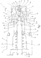
- Fig. 1 to 3 show the valve according to the invention in three switching states.
- Fig. 1 the valve is shown in the closed neutral position.
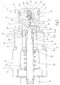
- Fig. 2 shows the valve the Fig. 1 in a working position with a low applied load pressure and
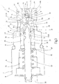
- Fig. 3 shows the valve the Fig. 1 in a working position at a high applied load pressure, in which the opening stroke of the main piston adjusted, ie reduced, is.
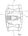
- Fig. 4 shows a section of the main piston in the region of the fluid inlet in longitudinal section.
- valve 1 is designed as a pilot-operated proportional directional control valve in cartridge design.
- the construction is based on a conventional proportional directional seat valve, in which a shrinkable inlet orifice 3 and a maximum volume flow regulator 5 have been integrated.
- the valve 1 can be used in a valve block, not shown.
- the valve housing 7 is designed to taper stepwise on the circumferential side 9, wherein the individual stages are designed as a hexagonal step 11, as a threaded step 13 and a simple step 15 and are sealed by circumferential ring seals 17, 19.
- the valve housing 7 has a lateral fluid inlet 21 and a bottom-side fluid outlet 23.
- a main piston 27 is inserted in an axial bore 25 of the valve housing 7. By the main piston 27, the fluid flow between the fluid inlet 21 and the fluid outlet 23 is controllable.
- the pilot valve 31 On a rear side 29 of the main piston 27, a pilot valve 31 is provided.
- the pilot valve 31 includes a pilot valve closing member 33, which cooperates with a pilot valve seat 35 in the main piston 27.
- the inlet orifice 3 is provided in the main piston 27.
- the inlet aperture 3 has a plurality of aperture bores 39, 41.
- Each aperture bore 39, 41 comprises two sections 43, 45. In a radially outer section 43, the diameter of the aperture bores 39, 41 is greater than in an inner section 45.
- the aperture bores 39, 41 are arranged axially and circumferentially offset in the main piston 27 , All orifices 39, 41 are supplied via a circumferential circumferential groove 47 of the main piston 27 evenly with pilot fluid.
- a control element 49 in the form of a collar is provided on the pilot valve closing element 33, by means of which the diaphragm bores 39, 41 can be reduced or completely closed relative to the main piston 27 as a function of the axial position of the pilot valve closing element 33.
- the collar 49 has pressure relief holes 51 which are provided distributed over the circumference. Due to this design, the control behavior of the pilot valve closing member 33 is changed only imperceptibly due to the collar 49.
- the inlet aperture 3 may be provided near or at a greater axial distance from the pilot valve seat 35.
- the inlet aperture 3 is additionally assigned a slit aperture 53.
- the slit diaphragm 53 is located between the fluid inlet 21 and the inlet orifice 3 and is formed by an annular gap 55 between the main piston 27 and the valve housing 7.
- the slit diaphragm 53 has a filtration function. It is to be prevented that larger particles of the fluid can penetrate into the pilot valve 31 and clog it. This would inevitably lead to a failure of the valve 1.
- the pilot valve closing member 33 has a pointed cone 57 and cooperates with the adapted thereto pilot valve seat 35 at one end 59 of an axial bore 61 of the main piston 27.
- the pilot valve closing member 33 is acted upon by a stiff spring 63, which is supported via a disc 65 and a snap ring 67 on the pilot valve closing member 33.
- a stiff spring 63 which is supported via a disc 65 and a snap ring 67 on the pilot valve closing member 33.
- the actuator 69 is designed as a pulling actuator 69 to pull the pilot valve closing member 33 when energized from the pilot valve seat 35.
- the maximum volume flow regulator 5 Downstream of the pilot valve seat 35 is located in the main piston 27 of the maximum volume flow controller 5.
- the maximum volume flow regulator 5 is disposed in a drain 71 between the pilot chamber 37 and the fluid outlet 23.
- the maximum volume flow regulator 5 comprises a control piston 73, which is acted upon by the pilot fluid flow on the front side 75 and by a spring 79 in the opposite direction on a rear side 77.
- the control piston 73 has a fluid passage 81 with a lateral, serving as a metering orifice inlet opening 83. Consequently, the pilot fluid can penetrate into the control piston 73 and drain into the fluid outlet 23 through radial bores 85, 87 forming a control diaphragm in the control piston 73 and in the main piston 27.
- the metering orifice has a flow control function.
- the rear side 77 of the control piston 73 is acted upon by the pressure reduced by means of the control diaphragm.
- the bores 85, 87 in the control piston 73 and the main piston 27 thereby form control edges of the maximum volume flow regulator 5, which limit the opening cross section as a function of the position of the control piston 73.
- the spring 79 is positioned between a recess 89 of the control piston 73 and a recess 91 of an end cap 93 fixed in the main piston 27.
- the control piston 73 is inserted into the axial bore 61 of the main piston 27.
- the end cap 93 is screwed into an internal thread 95 of the axial bore 61 or clamped in the axial bore 61.
- an adjustable maximum limit of the opening stroke of the main piston 27 is provided.
- a mechanically adjustable maximum stroke limitation on the actuating device 69 it is possible to mechanically set the maximum volume flow of the valve 1 independently of the magnetic force of the actuating device 69.
- a section of the main piston 27 in the region of the fluid inlet 21 is shown.
- the main piston 27 is provided immediately adjacent to a conical main valve surface 97 in the direction of the fluid outlet 23 with a circumferential constriction 99 which is V-shaped.
- a valve 1 is provided, whose opening stroke is dependent on the one hand on the actuator 69 and on the other hand of at the fluid inlet 21 pending load pressure.
- a high load pressure causes the opening stroke to be lower. If the load pressure is too low, the opening stroke can be increased by increasing the inlet orifice 3.
- the solution according to the invention also requires less installation space than the known solutions in which a conventional proportional directional seat valve is followed by a maximum volume flow controller or a pressure compensator, whether or not the integration of the volume flow control. Ultimately, it is also cheaper to produce.
Landscapes
- Engineering & Computer Science (AREA)
- General Engineering & Computer Science (AREA)
- Mechanical Engineering (AREA)
- Physics & Mathematics (AREA)
- Fluid Mechanics (AREA)
- Fluid-Driven Valves (AREA)
- Safety Valves (AREA)
- Lift Valve (AREA)
Description
- Die Erfindung betrifft ein Ventil, insbesondere ein vorgesteuertes Proportional-Wegesitzventil, mit den Merkmalen im Oberbegriff von Anspruch 1.
- Das proportionale Lastabsenken von Lastgabeln bei Gabelstaplern wird häufig von Sitzventilen mit stetigem Öffnungsverhalten mit veranlasst. Die dahingehenden Sitzventile können direkt betätigt oder vorgesteuert sein. Der Einsatz von Sitzventilen ist insbesondere deshalb geboten, weil von den Gabelstaplerherstellern ein sogenanntes "staplerdichtes" Lastverhalten gefordert wird, welches nur sehr geringe Leckagen zulässt. Durch das Vermeiden von Leckagen im hydraulischen Kreis ist sichergestellt, dass die Lastgabel mit oder ohne Beladung nicht eigenmächtig absinken kann, was ein Sicherheitsproblem darstellen würde.
- Eine lastunabhängige Maximal-Volumenstrombegrenzung wird bei bekannten Lösungen von einem in Reihe mit den anderen Komponenten des hydraulischen Kreises geschalteten Konstant-Volumenstromregler übernommen. Auf diese Weise wird die Forderung erfüllt, dass eine maximale Senkgeschwindigkeit einer Lastgabel unabhängig vom anstehenden Lastdruck nicht überschritten werden darf. Die dahingehend bekannten Steuervorrichtungen sind insofern nachteilig, als beim Absenken der Lastgabel ohne Last nur das Eigengewicht der bewegten Teile, insbesondere in Form der Lastgabel, am Hubmast zur Verfügung steht, um das Hydraulikfluid vom Arbeitszylinder (Plunger-Zylinder) zurück zum Tank als Bestandteil des hydraulischen Kreises zu fördern. Bei bestimmten Hubmastausführungen kann der Druck am Zylinder auf Werte < 10 bar abfallen. Je mehr Komponenten nun beim Absenken durchströmt werden müssen, desto geringer wird der sich einstellende Volumenstrom ausfallen. Dabei stellt der bekannte Konstant-Volumenstromregler eine besonders hohe Hürde dar, weil seine Zulaufblende so klein gewählt werden muss, dass sich eine Regeldruckdifferenz von mindestens 7 bar einstellen kann. Kleinere Regeldrücke würden zu instabilem Verhalten im hydraulischen Kreis der Arbeitseinrichtung führen und können gleichfalls aus Sicherheitsgründen nicht hingenommen werden. Darüber hinaus darf es auch bei kleinen Regeldruckdifferenzen keine merklichen Sinkgeschwindigkeitseinbußen geben. Der Einsatz einer Maximal-Volumenstrombegrenzung hat darüber hinaus den Nachteil, dass beim Übergang von der Maximal-Volumenstrombegrenzung zurück in die proportionale Kennlinie ein nachteiliger Rücksprung auftritt, der sich in einer diskontinuierlichen Bewegung einer Lastgabel bemerkbar macht, was ein weiteres Sicherheitsproblem darstellen kann. Letztlich verursacht ein in Reihe geschalteter Stromregler einen nicht unerheblichen Druckverlust, der das Senken der Last stark verlangsamt.
- Zusätzlich wird von den Kunden eine fallende Kennlinie für den Volumenstromregler gefordert. So soll aus Sicherheits- und Praktikabilitätsgründen gewährleistet sein, dass mit größer werdender Last die Senkgeschwindigkeit gleich oder geringer ausfällt. Wird dies bei den bekannten Steuervorrichtungen über den Konstant-Volumenstromregler durchgeführt, führt dies gleichfalls prinzipiell zu einer erhöhten Instabilität innerhalb des hydraulischen Kreises.
- Als Alternative zur Lösung mit einem in Reihe geschalteten Maximalvolumenstromregler wurde von der Anmelderin in der
DE 101 02 409 A1 eine Steuervorrichtung offenbart, bei der in einem hydraulischen Kreis ein Proportional-Wegesitzventil und eine Druckwaage in Reihe geschaltet sind. Seitens der Anwender dieser Lösungen gibt es nun die weitergehende Forderung nach einem noch kostengünstigeren und Bauraum sparenden Ventil. DieDE 199 55 522 A1 beschreibt ein Ventil, insbesondere vorgesteuertes Proportional-Wegesitzventil, mit einem Ventilgehäuse, das einen Fluideinlass und einen Fluidauslass aufweist, wobei der Fluidstrom zwischen Fluideinlass und Fluidauslass durch einen Hauptkolben regelbar ist, wobei auf einer Rückseite des Hauptkolbens eine Vorsteuerventilkammer mit einem durch eine Betätigungseinrichtung bewegbaren Vorsteuerventilschließglied vorgesehen ist, mit welchem der Fluidstrom zwischen der Vorsteuerventilkammer und dem Fluidauslass regelbar ist, wobei zwischen dem Fluideinlass und der Vorsteuerventilkammer eine einzige Zulaufblende angeordnet ist, wobei der Öffnungsquerschnitt der Zulaufblende durch ein Steuerelement verkleinerbar ist. Ein gattungsgemäßes Proportional-Wegesitzventil ist ausDE 197 55 120 A1 bekannt. Der Erfindung liegt daher die Aufgabe zugrunde, ein Ventil, insbesondere ein vorgesteuertes Proportional-Wegesitzventil, aufzuzeigen, das im Wesentlichen leckagefrei ist, dessen Senkgeschwindigkeit unabhängig vom anstehenden Lastdruck ist, das bei weniger als 10 bar Druckdifferenz ohne merkliche Sinkgeschwindigkeitseinbuße arbeitet, das zudem kostengünstig ist und das wenig Bauraum beansprucht. - Diese Aufgabe wird durch ein Ventil, insbesondere ein vorgesteuertes Proportional-Wegesitzventil, mit den Merkmalen von Anspruch 1 gelöst. Vorteilhafte Ausführungsformen des Ventils gehen aus den Unteransprüchen hervor.
- Gemäß dem Kennzeichen von Anspruch 1 ist vorgesehen, dass die Zulaufblende mehrere Blendenbohrungen aufweist und dass der Öffnungsquerschnitt von wenigstens einer der Blendenbohrungen durch das Steuerelement verkleinerbar ist.
- Die Aufspaltung der Zulaufblende in mehrere Blendenbohrungen ermöglicht es, die Zulaufblende sehr einfach in mehreren Öffnungsstufen zu schalten.
- Der Kerngedanke der Erfindung ist, einen Stromregler in das Ventil zu integrieren. Erfindungsgemäß ist deshalb der Öffnungsquerschnitt der Zulaufblende durch ein Steuerelement verkleinerbar. Der verkleinerte Zulaufblendenquerschnitt bewirkt, dass der Druck in der Vorsteuerventilkammer sinkt. Mit dieser Maßnahme ist es möglich, den Öffnungshub des Hauptkolbens zusätzlich zur Regulierung am Vorsteuerventilsitz aktiv zu regeln. Je kleiner der Differenzdruck zwischen Fluideinlass und Fluidauslass, desto größer kann der Öffnungshub des Ventils eingeregelt werden. Somit ist die Stromregelfunktion ermöglicht.
- Vorteilhaft wird durch diese Lösung ein zusätzlicher in Reihe geschalteter Konstant-Volumenstromregler oder eine ebenfalls in Reihe geschaltete Druckwaage eingespart. Dadurch ergeben sich geringere Herstellkosten und ein wesentlich verringerter erforderlicher Bauraum.
- Dadurch, dass nur noch das die Vorsteuerventilkammer passierende Fluid hinsichtlich des Volumenstroms geregelt wird, anstelle des gesamten Fluidstroms, wie bei den bekannten Lösungen mit einem nachgeschalteten Volumenstromregler oder eine Druckwaage, ergibt sich auch ein geringerer Druckverlust und damit eine erhöhte Effizienz.
- Mithin ist es möglich, den Öffnungshub des Hauptkolbens vom Differenzdruck des Ventils abhängig zu machen. Je größer der Differenzdruck, desto kleiner kann der Öffnungshub des Ventils eingestellt werden. Somit ist eine Stromregelfunktion möglich, bei der eine Zulaufmessblende alleine ohne zusätzliche Stromregelkante auskommt. Damit die vom Konstant-Stromregler vorgegebene Vorsteuerfluidmenge die Zulaufmessblende passieren kann, muss je nach Differenzdruck ein verschieden großer Blendenquerschnitt geöffnet werden. Der lastabhängige, variable Öffnungsquerschnitt der Zulaufmessblende ist eine Voraussetzung für einen lastunabhängigen Volumenstrom durch das Ventil.
- Bevorzugt ist das Steuerelement dem Vorsteuerventilschließglied zugeordnet. Beispielsweise kann das Steuerelement als radialer Vorsprung am Vorsteuerventilschließglied ausgebildet sein. Mithin kann durch eine axiale oder rotierende Bewegung des Vorsteuerventilschließgliedes der Öffnungsquerschnitt der Zulaufblende verändert werden. Somit muss keine separate Steuereinrichtung für das Steuerelement vorgesehen werden.
- Besonders vorteilhaft ist das Steuerelement als Bund am Vorsteuerventilschließglied ausgebildet, wobei der Bund wenigstens eine Druckentlastungsbohrung aufweist. Ein Bund ist ein umlaufender Vorsprung oder Flansch am Vorsteuerventilschließglied. Diese Gestaltung hat den Vorteil, dass das Vorsteuerventilschließglied zusätzlich gegenüber dem Hauptkolben zentriert wird und der Vorsprung am Vorsteuerventilschließglied stets auf die Zulaufblende hin ausgerichtet ist. Es können auch mehrere Druckentlastungsbohrungen vorgesehen sein, die über den Umfang verteilt angeordnet sind.
- Die Blendenbohrungen weisen darüber hinaus vorzugsweise gleiche Durchmesser auf. Die Blendenbohrungen können aber auch unterschiedliche Durchmesser haben, um das Regelverhalten des Ventils zusätzlich an die unterschiedlichen anstehenden Lastdrücke anzupassen und um der Regelung eine von der Linearität abweichende Charakteristik zu geben.
- Zweckmäßigerweise sind die Blendenbohrungen axial und/oder über den Umfang zueinander versetzt im Hauptkolben angeordnet. Diese Anordnung der Blendenbohrungen erleichtert zusätzlich das Verkleinern des Öffnungsquerschnitts mit Hilfe des Vorsteuerventilschließgliedes. Durch die axiale Verlagerung des Vorsteuerventilschließgliedes relativ zum Hauptkolben können so eine oder mehrere in axialer Richtung hintereinander liegende Blendenbohrungen verschlossen werden. Über den Umfang verteilte Blendenbohrungen sind darüber einfacher herzustellen, da die Blendenbohrungen Abschnitte mit unterschiedlichen Durchmessern aufweisen. Somit werden überlappende Blendenbohrungen oder Schwächungen der Wand des Hauptkolbens durch mehrere, konzentriert angeordnete Blendenbohrungen vermieden.
- Zweckmäßigerweise ist zwischen dem Fluideinlass und der Zulaufblende eine Spaltblende vorgesehen, die vorzugsweise in Form eines Ringspalts zwischen Ventilgehäuse und Hauptventilkolben ausgebildet ist. Die Spaltblende hat eine Filtrationsfunktion. Es soll verhindert werden, dass Partikel des Fluids in die stromabwärts gelegenen Einheiten des Vorsteuerventils eindringen. Dies kann zu Verstopfungen des Vorsteuerventils und damit zum Ausfall des Ventils insgesamt führen.
- In einer besonders bevorzugten Ausführungsform ist im Hauptkolben in einem Ablauf zwischen Vorsteuerventilkammer und Fluidauslass ein Maximalvolumenstromregler vorgesehen. Durch den Maximalvolumenstromregler kann der Strom des ablaufenden Vorsteuerfluids vorteilhaft lastunabhängig eingestellt werden. Auf diese Weise wird der Druck in der Vorsteuerventilkammer erhöht, so dass der Öffnungshub des Hauptkolbens lastdruckunabhängig verringert wird. Mithin öffnet das Ventil bei einem hohen anstehenden Lastdruck beispielsweise infolge einer hohen Last auf einer Lastgabel eines Gabelstaplers geringer. Die Sinkgeschwindigkeit der Lastgabel wird somit vorteilhaft reduziert. Durch die Integration des Maximalvolumenstromreglers in den Hauptkolben wird praktisch kein zusätzlicher Bauraum benötigt. Mithin ergibt sich gegenüber den Lösungen des Standes der Technik mit nachgeschalteten Regelelementen eine erhebliche Einsparung an Bauraum.
- Der Maximalvolumenstromregler weist bevorzugt einen Regelkolben auf, der auf einer Vorderseite vom Druck des aus der Vorsteuerkammer auslaufenden Fluids und auf einer Rückseite von einer Feder beaufschlagt ist. Zusätzlich kann der Regelkolben vom Druck in der Federkammer (dieser ist der mittels der Zulaufblende geminderte Druck) beaufschlagt sein. Diese Konstruktion hat den Vorteil, dass sie mit einer minimalen Anzahl von Teilen auskommt, die sich vorteilhaft nur in einer Richtung bewegen. Ein solcher Maximalvolumenstromregler ist daher einfach herstellbar und einstellbar.
- Weiterhin kann im Regelkolben ein Fluiddurchlass vorgesehen sein und durch Bohrungen im Regelkolben und im Hauptkolben können Regelkanten des Maximalvolumenstromreglers gebildet sein, wobei die Größe des durch die Regelkanten begrenzten Öffnungsquerschnitts von der Position des Regelkolbens abhängig ist. Mithin wird die Drosselfunktion des Maximalvolumenstromreglers auf besonders einfache Weise bereitgestellt.
- Vorteilhaft weist der Fluiddurchlass eine seitliche Einlassöffnung am Regelkolben auf.
- Der Regelkolben kann in eine axiale Bohrung des Hauptkolbens eingesetzt und vorzugsweise durch eine Endkappe in der axialen Bohrung gehalten sein. Diese Anordnung ist besonders effizient herstellbar und bauraumsparend realisierbar.
- Vorteilhaft ist vorgesehen, dass der Hauptkolben über das Vorsteuerventilschließglied durch eine Feder in eine Schließstellung beaufschlagt ist. Dies gewährleistet, dass das Ventil in der Neutralstellung weitgehend leckagefrei ist, so dass es während einer längeren Stillstandszeit beispielsweise nicht zu einem Absinken einer Lastgabel kommt. Darüber hinaus wirkt bei unterbrochenem Vorsteuerfluidstrom auf die Rückseite des Regelkolbens der Lastdruck am Fluideinlass, wodurch die Schließkraft des Hauptkolbens verstärkt und eine sehr gute Dichtungswirkung zwischen Fluideinlass und Fluidauslass erreicht wird.
- Das Vorsteuerventilschließglied ist von der Betätigungseinrichtung von einem Vorsteuerventilsitz wegziehbar. Die ziehende Ausführung der Betätigungseinrichtung ist ebenfalls unter dem oben genannten Sicherheitsaspekt vorteilhaft.
- Die Erfindung ist nachfolgend anhand von einem in den Figuren dargestellten Ausführungsbeispiel näher erläutert. Die
Fig. 1 bis 3 zeigen das erfindungsgemäße Ventil in drei Schaltzuständen. InFig. 1 ist das Ventil in der geschlossenen Neutralstellung gezeigt.Fig. 2 zeigt das Ventil derFig. 1 in einer Arbeitsstellung bei einem geringen anstehenden Lastdruck undFig. 3 zeigt das Ventil derFig. 1 in einer Arbeitsstellung bei einem hohen anstehenden Lastdruck, bei dem der Öffnungshub des Hauptkolbens eingeregelt, d.h. verringert, ist.Fig. 4 zeigt einen Ausschnitt des Hauptkolbens im Bereich des Fluideinlasses im Längsschnitt. - In den
Fig. 1 bis 3 ist das Ventil 1 als vorgesteuertes Proportional-Wegeventil in Cartridge-Bauweise ausgeführt. Die Konstruktion geht von einem herkömmlichen proportionalen Wege-Sitzventil aus, in das eine verkleinerbare Zulaufblende 3 und ein Maximalvolumenstromregler 5 integriert wurden. - Das Ventil 1 ist in einen nicht näher dargestellten Ventilblock einsetzbar. Das Ventilgehäuse 7 ist dazu auf der Umfangsseite 9 stufenweise verjüngt ausgeführt, wobei die einzelnen Stufen als Sechskantstufe 11, als Gewindestufe 13 und als einfache Stufe 15 ausgeführt sind sowie über umlaufende Ringdichtungen 17, 19 abgedichtet sind. Das Ventilgehäuse 7 weist einen seitlichen Fluideinlass 21 und einen bodenseitigen Fluidauslass 23 auf. In eine axiale Bohrung 25 des Ventilgehäuses 7 ist ein Hauptkolben 27 eingesetzt. Durch den Hauptkolben 27 ist der Fluidstrom zwischen dem Fluideinlass 21 und dem Fluidauslass 23 regelbar.
- Auf einer Rückseite 29 des Hauptkolbens 27 ist ein Vorsteuerventil 31 vorgesehen. Das Vorsteuerventil 31 umfasst ein Vorsteuerventilschließglied 33, welches mit einem Vorsteuerventilsitz 35 im Hauptkolben 27 zusammenwirkt.
- Zur Begrenzung des Zuflusses von Vorsteuerfluid zur Vorsteuerventilkammer 37 ist im Hauptkolben 27 die Zulaufblende 3 vorgesehen. Die Zulaufblende 3 weist mehrere Blendenbohrungen 39, 41 auf. Jede Blendenbohrung 39, 41 umfasst zwei Abschnitte 43, 45. In einem radial äußeren Abschnitt 43 ist der Durchmesser der Blendenbohrungen 39, 41 größer als in einem inneren Abschnitt 45. Die Blendenbohrungen 39, 41 sind axial und über den Umfang versetzt im Hauptkolben 27 angeordnet. Alle Blendenbohrungen 39, 41 werden über eine umlaufende Umfangsnut 47 des Hauptkolbens 27 gleichmäßig mit Vorsteuerfluid versorgt. Zur Verkleinerung des Öffnungsquerschnitts der Zulaufblende 3 ist am Vorsteuerventilschließglied 33 ein Steuerelement 49 in Form eines Bundes vorgesehen, durch welchen die Blendenbohrungen 39, 41 in Abhängigkeit von der axialen Stellung des Vorsteuerventilschließgliedes 33 relativ zum Hauptkolben 27 verkleinerbar oder ganz verschließbar sind. Je weiter das Vorsteuerventilschließglied 33 aus dem Hauptkolben 27 herausgezogen wird, desto mehr wird der Öffnungsquerschnitt der Zulaufblende 3 reduziert. Der Bund 49 weist Druckentlastungsbohrungen 51 auf, die über den Umfang verteilt vorgesehen sind. Durch diese Gestaltung wird das Regelverhalten des Vorsteuerventilschließgliedes 33 aufgrund des Bundes 49 nur unmerklich verändert. Die Zulaufblende 3 kann in der Nähe oder in einem größeren axialen Abstand zum Vorsteuerventilsitz 35 vorgesehen sein. Wenn die Zulaufblende 3 hinreichend nahe am Vorsteuerventilsitz 35 angeordnet ist, überlappen sich die Regelungsbereiche des Vorsteuerventils 31 und der Steuerung des Öffnungsquerschnittes der Zulaufblende 3. Bei ausreichend großem Abstand muss sich das Vorsteuerventilschließglied 33 zunächst soweit vom Vorsteuerventilsitz 35 entfernen, dass dieses vollständig geöffnet ist, ehe es zu einer Verkleinerung des Öffnungsquerschnittes der Zulaufblende 3 kommt.
- Der Zulaufblende 3 ist zusätzlich eine Spaltblende 53 zugeordnet. Die Spaltblende 53 befindet sich zwischen dem Fluideinlass 21 und der Zulaufblende 3 und ist durch einen Ringspalt 55 zwischen dem Hauptkolben 27 und dem Ventilgehäuse 7 ausgebildet. Die Spaltblende 53 hat eine Filtrationsfunktion. Es soll verhindert werden, dass größere Partikel des Fluids in das Vorsteuerventil 31 eindringen und es verstopfen können. Dies würde unweigerlich zu einem Ausfall des Ventils 1 führen.
- Das Vorsteuerventilschließglied 33 hat einen Spitzkegel 57 und wirkt mit dem daran angepassten Vorsteuerventilsitz 35 an einem Ende 59 einer axialen Bohrung 61 des Hauptkolbens 27 zusammen. Das Vorsteuerventilschließglied 33 ist durch eine steife Feder 63, die sich über eine Scheibe 65 und einen Sprengring 67 am Vorsteuerventilschließglied 33 abstützt, beaufschlagt. Somit ist bei einer inaktiven Betätigungseinrichtung 69 das Ventil 1 in die Sperrstellung (
Fig. 1 ) vorgespannt. - Die Betätigungseinrichtung 69 ist als ziehende Betätigungseinrichtung 69 ausgeführt, um das Vorsteuerventilschließglied 33 bei Bestromung vom Vorsteuerventilsitz 35 wegzuziehen.
- Stromab des Vorsteuerventilsitzes 35 befindet sich im Hauptkolben 27 der Maximalvolumenstromregler 5. Der Maximalvolumenstromregler 5 ist in einem Ablauf 71 zwischen der Vorsteuerkammer 37 und dem Fluidauslass 23 angeordnet. Der Maximalvolumenstromregler 5 umfasst einen Regelkolben 73, der auf der Vorderseite 75 vom Vorsteuerfluidstrom und auf einer Rückseite 77 durch eine Feder 79 in entgegengesetzter Richtung beaufschlagt ist. Der Regelkolben 73 weist einen Fluiddurchlass 81 mit einer seitlichen, als Messblende dienenden Einlassöffnung 83 auf. Mithin kann das Vorsteuerfluid in den Regelkolben 73 eindringen und durch radiale, eine Regelblende bildende Bohrungen 85, 87 im Regelkolben 73 und im Hauptkolben 27 in den Fluidauslass 23 abfließen. Die Messblende hat eine Stromregelfunktion. Abhängig von der Öffnungsstellung der durch die Bohrungen 85, 87 gebildeten Regelblende ist die Rückseite 77 des Regelkolbens 73 vom mittels der Regelblende reduzierten Druckes beaufschlagt. Die Bohrungen 85, 87 in dem Regelkolben 73 und dem Hauptkolben 27 bilden dabei Regelkanten des Maximalvolumenstromreglers 5 aus, die den Öffnungsquerschnitt in Abhängigkeit von der Position des Regelkolbens 73 begrenzen. Die Feder 79 ist zwischen einer Ausnehmung 89 des Regelkolbens 73 und einer Ausnehmung 91 einer im Hauptkolben 27 befestigten Endkappe 93 positioniert. Um die Konstruktion so einfach wie möglich zu halten, ist der Regelkolben 73 in die axiale Bohrung 61 des Hauptkolbens 27 eingesetzt. Die Endkappe 93 ist in ein Innengewinde 95 der axialen Bohrung 61 eingeschraubt oder in der axialen Bohrung 61 klemmend gehalten.
- Zusätzlich ist eine einstellbare maximale Begrenzung des Öffnungshubes des Hauptkolbens 27 vorgesehen. Mit Hilfe einer mechanisch einstellbaren Maximal-Hubbegrenzung an der Betätigungseinrichtung 69 ist es möglich, den maximalen Volumenstrom des Ventils 1 unabhängig von der Magnetkraft der Betätigungseinrichtung 69 mechanisch einzustellen.
- In der
Fig. 4 ist ein Ausschnitt des Hauptkolbens 27 im Bereich des Fluideinlasses 21 gezeigt. Der Hauptkolben 27 ist unmittelbar angrenzend an eine kegelförmige Hauptventilfläche 97 in Richtung auf den Fluidauslass 23 mit einer umlaufenden Einschnürung 99 versehen, die V-förmig ausgebildet ist. - Auf diese Weise wird ein Ventil 1 bereitgestellt, dessen Öffnungshub einerseits abhängig ist von der Betätigungseinrichtung 69 und andererseits vom am Fluideinlass 21 anstehenden Lastdruck. Ein hoher Lastdruck bewirkt, dass der Öffnungshub geringer ausfällt. Ist der Lastdruck zu gering kann durch Vergrößern der Zulaufblende 3 der Öffnungshub vergrößert werden. Damit werden die Forderungen nach einem leckagefreien Ventil 1, das auch bei einer geringen Druckdifferenz einen gleichmäßigen Volumenstrom gewährleistet und das unabhängig vom anstehenden Lastdruck ist, erfüllt.
- Die erfindungsgemäße Lösung benötigt ob der Integration der Volumenstromregelung zudem weniger Bauraum als die bekannten Lösungen, bei denen einem herkömmlichen Proportional-Wegesitzventil ein Maximalvolumenstromregler oder eine Druckwaage nachgeschaltet ist. Letztlich ist es auch kostengünstiger herstellbar.
Claims (14)
- Ventil, insbesondere vorgesteuertes Proportional-Wegesitzventil, mit einem Ventilgehäuse (7), das einen Fluideinlass (21) und einen Fluidauslass (23) aufweist, wobei der Fluidstrom zwischen Fluideinlass (21) und Fluidauslass (23) durch einen Hauptkolben (27) regelbar ist, wobei auf einer Rückseite (29) des Hauptkolbens (27) eine Vorsteuerventilkammer (37) vorgesehen ist mit einem durch eine Betätigungseinrichtung (69) bewegbaren Vorsteuerventilschließglied (33), mit welchem der Fluidstrom zwischen der Vorsteuerventilkammer (37) und dem Fluidauslass (23) regelbar ist, wobei zwischen dem Fluideinlass (21) und der Vorsteuerventilkammer (37) eine Zulaufblende (3) angeordnet ist, wobei der Öffnungsquerschnitt der Zulaufblende (3) durch ein Steuerelement (49) verkleinerbar ist, dadurch gekennzeichnet, dass die Zulaufblende (3) mehrere Blendenbohrungen (39, 41) aufweist und dass der Öffnungsquerschnitt von wenigstens einer der Blendenbohrungen (39, 41) durch das Steuerelement (49) verkleinerbar ist, wobei es die Aufspaltung der Zulaufblende (3) in mehrere Blendenbohrungen ermöglicht, die Zulaufblende (3) in mehreren Öffnungsstufen zu schalten.
- Ventil nach Anspruch 1, dadurch gekennzeichnet, dass das Steuerelement (49) dem Vorsteuerventilschließglied (33) zugeordnet ist.
- Ventil nach Anspruch 2, dadurch gekennzeichnet, dass das Steuerelement (49) als radialer Vorsprung am Vorsteuerventilschließglied (33) ausgebildet ist.
- Ventil nach Anspruch 3, dadurch gekennzeichnet, dass das Steuerelement (49) als Bund am Vorsteuerventilschließglied (33) ausgebildet ist, wobei der Bund (49) wenigstens eine Druckentlastungsbohrung (51) aufweist.
- Ventil nach einem der vorhergehenden Ansprüche, dadurch gekennzeichnet, dass die Blendenbohrungen (39, 41) gleiche Durchmesser aufweisen.
- Ventil nach einem der vorhergehenden Ansprüche, dadurch gekennzeichnet, dass die Blendenbohrungen (39, 41) axial und/oder über den Umfang zueinander versetzt im Hauptkolben (27) angeordnet sind.
- Ventil nach einem der vorhergehenden Ansprüche, dadurch gekennzeichnet, dass zwischen Fluideinlass (21) und Zulaufblende (3) eine Spaltblende (53) vorgesehen ist, die vorzugsweise in Form eines Ringspalts (55) zwischen Ventilgehäuse (7) und Hauptventilkolben ausgebildet (27) ist.
- Ventil nach einem der vorhergehenden Ansprüche, dadurch gekennzeichnet, dass im Hauptkolben (27) in einem Ablauf zwischen Vorsteuerventilkammer (37) und Fluidauslass (23) ein Maximalvolumenstromregler (5) vorgesehen ist.
- Ventil nach Anspruch 8, dadurch gekennzeichnet, dass der Maximalvolumenstromregler (5) einen Regelkolben (73) aufweist, der auf einer Vorderseite (75) vom Druck des aus der Vorsteuerkammer ablaufenden Fluids und auf einer Rückseite (77) von einer Feder (79) beaufschlagt ist.
- Ventil nach Anspruch 9, dadurch gekennzeichnet, dass im Regelkolben (73) ein Fluiddurchlass (81) vorgesehen ist und durch Bohrungen (85, 87) im Regelkolben (73) und im Hauptkolben (27) Regelkanten des Maximalvolumenstromreglers (5) gebildet sind, wobei die Größe des durch die Regelkanten begrenzten Öffnungsquerschnitts von der Position des Regelkolbens (73) abhängig ist.
- Ventil nach Anspruch 10, dadurch gekennzeichnet, dass der Fluiddurchlass (81) eine seitliche Einlassöffnung (83) am Regelkolben (73) aufweist.
- Ventil nach einem der Ansprüche 9 bis 11, dadurch gekennzeichnet, dass der Regelkolben (73) in eine axiale Bohrung (61) des Hauptkolbens (27) eingesetzt ist und vorzugsweise durch eine Endkappe (93) in der axialen Bohrung (61) gehalten ist.
- Ventil nach einem der vorhergehenden Ansprüche, dadurch gekennzeichnet, dass der Hauptkolben (27) über das Vorsteuerventilschließglied (33) durch eine Feder (63) in eine Sperrstellung beaufschlagt ist.
- Ventil nach einem der vorhergehenden Ansprüche, dadurch gekennzeichnet, dass das Vorsteuerventilschließglied (33) von der Betätigungseinrichtung (69) von einem Vorsteuerventilsitz (35) wegziehbar ist.
Applications Claiming Priority (2)
| Application Number | Priority Date | Filing Date | Title |
|---|---|---|---|
| DE102012015354.6A DE102012015354A1 (de) | 2012-08-03 | 2012-08-03 | Ventil, insbesondere vorgesteuertes Proportional-Wegesitzventil |
| PCT/EP2013/002129 WO2014019647A1 (de) | 2012-08-03 | 2013-07-18 | Ventil, insbesondere vorgesteuertes proportional-wegesitzventil |
Publications (2)
| Publication Number | Publication Date |
|---|---|
| EP2880315A1 EP2880315A1 (de) | 2015-06-10 |
| EP2880315B1 true EP2880315B1 (de) | 2017-09-20 |
Family
ID=48803498
Family Applications (1)
| Application Number | Title | Priority Date | Filing Date |
|---|---|---|---|
| EP13739146.2A Active EP2880315B1 (de) | 2012-08-03 | 2013-07-18 | Ventil, insbesondere vorgesteuertes proportional-wegesitzventil |
Country Status (5)
| Country | Link |
|---|---|
| US (1) | US9664291B2 (de) |
| EP (1) | EP2880315B1 (de) |
| JP (1) | JP6294318B2 (de) |
| DE (1) | DE102012015354A1 (de) |
| WO (1) | WO2014019647A1 (de) |
Cited By (1)
| Publication number | Priority date | Publication date | Assignee | Title |
|---|---|---|---|---|
| WO2023166075A1 (de) | 2022-03-04 | 2023-09-07 | Hydac Fluidtechnik Gmbh | Ventil |
Families Citing this family (4)
| Publication number | Priority date | Publication date | Assignee | Title |
|---|---|---|---|---|
| DE102012015356A1 (de) * | 2012-08-03 | 2014-05-15 | Hydac Fluidtechnik Gmbh | Ventil, insbesondere vorgesteuertes Proportional-Wegesitzventil |
| CN105081245A (zh) * | 2015-08-21 | 2015-11-25 | 重庆煜琨珑冶金材料有限公司 | 粉末物料流量调节器 |
| DE102022004033A1 (de) | 2022-10-28 | 2024-05-08 | Hydac Fluidtechnik Gmbh | Ventil |
| DE102023000400A1 (de) * | 2023-02-09 | 2024-08-29 | Hydac Fluidtechnik Gmbh | Ventil |
Family Cites Families (13)
| Publication number | Priority date | Publication date | Assignee | Title |
|---|---|---|---|---|
| US3604446A (en) * | 1969-05-26 | 1971-09-14 | Garrett Corp | Valve |
| CH661107A5 (de) * | 1985-03-22 | 1987-06-30 | Sulzer Ag | Vorgesteuertes ventil. |
| CH671080A5 (de) | 1986-10-01 | 1989-07-31 | Sulzer Ag | |
| JP3145233B2 (ja) * | 1992-08-07 | 2001-03-12 | 株式会社鷺宮製作所 | 双方向電磁弁 |
| DE19755120A1 (de) | 1997-02-27 | 1998-09-03 | Mannesmann Rexroth Ag | Vorgesteuertes Sperrventil |
| DE19955522A1 (de) | 1999-11-18 | 2001-05-23 | Bosch Gmbh Robert | Vorrichtung zur Steuerung eines hydraulischen Volumenstroms |
| DE10039936A1 (de) * | 2000-08-16 | 2002-03-07 | Fluidtech Gmbh | Ventil |
| IT1316974B1 (it) * | 2000-12-21 | 2003-05-13 | Edi System S P A | Valvola a due vie ad azionamento elettromagnetico. |
| DE10102409A1 (de) | 2001-01-15 | 2002-07-25 | Hydac Fluidtechnik Gmbh | Steuervorrichtung für eine an einen hydraulischen Kreis angeschlossene Arbeitseinrichtung |
| DE102008006380A1 (de) | 2008-01-29 | 2009-07-30 | Hydac Fluidtechnik Gmbh | Vorgesteuertes Ventil, insbesondere Proportional-Drosselventil |
| DE102010001881B4 (de) * | 2010-02-12 | 2012-08-30 | Reinhold Schulte | Agrarspritzen-Ventileinheit |
| DE102012015356A1 (de) * | 2012-08-03 | 2014-05-15 | Hydac Fluidtechnik Gmbh | Ventil, insbesondere vorgesteuertes Proportional-Wegesitzventil |
| DE102012107278A1 (de) * | 2012-08-08 | 2014-02-13 | Nordischer Maschinenbau Rud. Baader Gmbh + Co. Kg | Verfahren und Vorrichtung zur Überwachung einer Fleischverarbeitungsmaschine |
-
2012
- 2012-08-03 DE DE102012015354.6A patent/DE102012015354A1/de not_active Withdrawn
-
2013
- 2013-07-18 EP EP13739146.2A patent/EP2880315B1/de active Active
- 2013-07-18 JP JP2015524658A patent/JP6294318B2/ja not_active Expired - Fee Related
- 2013-07-18 US US14/417,912 patent/US9664291B2/en active Active
- 2013-07-18 WO PCT/EP2013/002129 patent/WO2014019647A1/de active Application Filing
Non-Patent Citations (1)
| Title |
|---|
| None * |
Cited By (4)
| Publication number | Priority date | Publication date | Assignee | Title |
|---|---|---|---|---|
| WO2023166075A1 (de) | 2022-03-04 | 2023-09-07 | Hydac Fluidtechnik Gmbh | Ventil |
| WO2023166073A1 (de) | 2022-03-04 | 2023-09-07 | Hydac Fluidtechnik Gmbh | Ventil |
| DE102022000767A1 (de) | 2022-03-04 | 2023-09-07 | Hydac Fluidtechnik Gmbh | Ventil |
| WO2023165745A1 (de) | 2022-03-04 | 2023-09-07 | Hydac Fluidtechnik Gmbh | Vorgesteuertes elektromagnetventil |
Also Published As
| Publication number | Publication date |
|---|---|
| JP6294318B2 (ja) | 2018-03-14 |
| JP2015523524A (ja) | 2015-08-13 |
| US20150323083A1 (en) | 2015-11-12 |
| WO2014019647A1 (de) | 2014-02-06 |
| EP2880315A1 (de) | 2015-06-10 |
| DE102012015354A1 (de) | 2014-05-15 |
| US9664291B2 (en) | 2017-05-30 |
Similar Documents
| Publication | Publication Date | Title |
|---|---|---|
| EP0864794B1 (de) | Proportional-Drosselventil | |
| EP2880315B1 (de) | Ventil, insbesondere vorgesteuertes proportional-wegesitzventil | |
| EP2348376B1 (de) | Stromregelventil mit Dämpfungskammer | |
| DE102012220863A1 (de) | Steueranordnung | |
| EP2880316B1 (de) | Ventil, insbesondere vorgesteuertes proportional-wegesitzventil | |
| DE19855187A1 (de) | Verfahren und Steueranordnung zur Ansteuerung eines hydraulischen Verbrauchers | |
| DE102014017801A1 (de) | Druckbegrenzungsventil | |
| EP1984629B1 (de) | Hydraulische steueranordnung mit regeneration und senkbremsventil | |
| DE102012208944A1 (de) | Hydrostatische Ventilanordnung und hydrostatische Steueranordnung mit der Ventilanordnung | |
| EP1736671B1 (de) | LS-Steueranordnung und LS-Wegeventil | |
| DE10216119A1 (de) | Hydraulische Steueranordnung in Load-Sensing Technik | |
| DE19632368A1 (de) | Elektrohydraulisches Regelwegeventil | |
| EP2891805A2 (de) | Steueranordnung und Steuerventil für eine derartige Steueranordnung | |
| EP1381779B1 (de) | Wegeventil mit innenliegender druckwaage | |
| DE10107532A1 (de) | Wegeventil zur lastunabhängigen Steuerung eines hydraulischen Verbrauchers hinsichtlich Richtung und Geschwindigkeit | |
| EP1452744B1 (de) | Hydraulische Steueranordnung | |
| EP3679254B1 (de) | Ventil | |
| EP3309644B1 (de) | Ventilvorrichtung sowie druckregelsystem mit einer solchen ventilvorrichtung | |
| DE102008064138A1 (de) | Hydraulische Steueranordnung | |
| EP3258116B1 (de) | Hydraulikmodul mit druckgesteuertem 2-wege-stromregelventil | |
| DE3211545A1 (de) | Hydraulikventil zur druckmittelversorgung eines verbrauchers, insbesondere mengenregelventil | |
| DE3228430A1 (de) | Stetig verstellbares 2-wege-einbauventil | |
| EP0624732A1 (de) | Hydraulische Steuereinrichtung | |
| EP1481167A1 (de) | Ventilanordnung | |
| EP2908013A1 (de) | Hydraulisches Kippsystem für einen mittels eines Kippventils stetig steuerbaren, in der Senkgeschwindigkeit nicht durch das Kippventil begrenzten Senkbetrieb |
Legal Events
| Date | Code | Title | Description |
|---|---|---|---|
| PUAI | Public reference made under article 153(3) epc to a published international application that has entered the european phase |
Free format text: ORIGINAL CODE: 0009012 |
|
| 17P | Request for examination filed |
Effective date: 20150127 |
|
| AK | Designated contracting states |
Kind code of ref document: A1 Designated state(s): AL AT BE BG CH CY CZ DE DK EE ES FI FR GB GR HR HU IE IS IT LI LT LU LV MC MK MT NL NO PL PT RO RS SE SI SK SM TR |
|
| AX | Request for extension of the european patent |
Extension state: BA ME |
|
| DAX | Request for extension of the european patent (deleted) | ||
| GRAP | Despatch of communication of intention to grant a patent |
Free format text: ORIGINAL CODE: EPIDOSNIGR1 |
|
| INTG | Intention to grant announced |
Effective date: 20170419 |
|
| GRAS | Grant fee paid |
Free format text: ORIGINAL CODE: EPIDOSNIGR3 |
|
| GRAA | (expected) grant |
Free format text: ORIGINAL CODE: 0009210 |
|
| AK | Designated contracting states |
Kind code of ref document: B1 Designated state(s): AL AT BE BG CH CY CZ DE DK EE ES FI FR GB GR HR HU IE IS IT LI LT LU LV MC MK MT NL NO PL PT RO RS SE SI SK SM TR |
|
| REG | Reference to a national code |
Ref country code: GB Ref legal event code: FG4D Free format text: NOT ENGLISH |
|
| REG | Reference to a national code |
Ref country code: CH Ref legal event code: EP |
|
| REG | Reference to a national code |
Ref country code: AT Ref legal event code: REF Ref document number: 930393 Country of ref document: AT Kind code of ref document: T Effective date: 20171015 |
|
| REG | Reference to a national code |
Ref country code: IE Ref legal event code: FG4D Free format text: LANGUAGE OF EP DOCUMENT: GERMAN |
|
| REG | Reference to a national code |
Ref country code: DE Ref legal event code: R096 Ref document number: 502013008404 Country of ref document: DE |
|
| REG | Reference to a national code |
Ref country code: NL Ref legal event code: MP Effective date: 20170920 |
|
| PG25 | Lapsed in a contracting state [announced via postgrant information from national office to epo] |
Ref country code: SE Free format text: LAPSE BECAUSE OF FAILURE TO SUBMIT A TRANSLATION OF THE DESCRIPTION OR TO PAY THE FEE WITHIN THE PRESCRIBED TIME-LIMIT Effective date: 20170920 Ref country code: HR Free format text: LAPSE BECAUSE OF FAILURE TO SUBMIT A TRANSLATION OF THE DESCRIPTION OR TO PAY THE FEE WITHIN THE PRESCRIBED TIME-LIMIT Effective date: 20170920 Ref country code: LT Free format text: LAPSE BECAUSE OF FAILURE TO SUBMIT A TRANSLATION OF THE DESCRIPTION OR TO PAY THE FEE WITHIN THE PRESCRIBED TIME-LIMIT Effective date: 20170920 Ref country code: NO Free format text: LAPSE BECAUSE OF FAILURE TO SUBMIT A TRANSLATION OF THE DESCRIPTION OR TO PAY THE FEE WITHIN THE PRESCRIBED TIME-LIMIT Effective date: 20171220 Ref country code: FI Free format text: LAPSE BECAUSE OF FAILURE TO SUBMIT A TRANSLATION OF THE DESCRIPTION OR TO PAY THE FEE WITHIN THE PRESCRIBED TIME-LIMIT Effective date: 20170920 |
|
| REG | Reference to a national code |
Ref country code: LT Ref legal event code: MG4D |
|
| PG25 | Lapsed in a contracting state [announced via postgrant information from national office to epo] |
Ref country code: RS Free format text: LAPSE BECAUSE OF FAILURE TO SUBMIT A TRANSLATION OF THE DESCRIPTION OR TO PAY THE FEE WITHIN THE PRESCRIBED TIME-LIMIT Effective date: 20170920 Ref country code: LV Free format text: LAPSE BECAUSE OF FAILURE TO SUBMIT A TRANSLATION OF THE DESCRIPTION OR TO PAY THE FEE WITHIN THE PRESCRIBED TIME-LIMIT Effective date: 20170920 Ref country code: BG Free format text: LAPSE BECAUSE OF FAILURE TO SUBMIT A TRANSLATION OF THE DESCRIPTION OR TO PAY THE FEE WITHIN THE PRESCRIBED TIME-LIMIT Effective date: 20171220 Ref country code: GR Free format text: LAPSE BECAUSE OF FAILURE TO SUBMIT A TRANSLATION OF THE DESCRIPTION OR TO PAY THE FEE WITHIN THE PRESCRIBED TIME-LIMIT Effective date: 20171221 |
|
| PG25 | Lapsed in a contracting state [announced via postgrant information from national office to epo] |
Ref country code: NL Free format text: LAPSE BECAUSE OF FAILURE TO SUBMIT A TRANSLATION OF THE DESCRIPTION OR TO PAY THE FEE WITHIN THE PRESCRIBED TIME-LIMIT Effective date: 20170920 |
|
| PG25 | Lapsed in a contracting state [announced via postgrant information from national office to epo] |
Ref country code: RO Free format text: LAPSE BECAUSE OF FAILURE TO SUBMIT A TRANSLATION OF THE DESCRIPTION OR TO PAY THE FEE WITHIN THE PRESCRIBED TIME-LIMIT Effective date: 20170920 Ref country code: PL Free format text: LAPSE BECAUSE OF FAILURE TO SUBMIT A TRANSLATION OF THE DESCRIPTION OR TO PAY THE FEE WITHIN THE PRESCRIBED TIME-LIMIT Effective date: 20170920 Ref country code: ES Free format text: LAPSE BECAUSE OF FAILURE TO SUBMIT A TRANSLATION OF THE DESCRIPTION OR TO PAY THE FEE WITHIN THE PRESCRIBED TIME-LIMIT Effective date: 20170920 Ref country code: CZ Free format text: LAPSE BECAUSE OF FAILURE TO SUBMIT A TRANSLATION OF THE DESCRIPTION OR TO PAY THE FEE WITHIN THE PRESCRIBED TIME-LIMIT Effective date: 20170920 |
|
| PG25 | Lapsed in a contracting state [announced via postgrant information from national office to epo] |
Ref country code: EE Free format text: LAPSE BECAUSE OF FAILURE TO SUBMIT A TRANSLATION OF THE DESCRIPTION OR TO PAY THE FEE WITHIN THE PRESCRIBED TIME-LIMIT Effective date: 20170920 Ref country code: SM Free format text: LAPSE BECAUSE OF FAILURE TO SUBMIT A TRANSLATION OF THE DESCRIPTION OR TO PAY THE FEE WITHIN THE PRESCRIBED TIME-LIMIT Effective date: 20170920 Ref country code: IS Free format text: LAPSE BECAUSE OF FAILURE TO SUBMIT A TRANSLATION OF THE DESCRIPTION OR TO PAY THE FEE WITHIN THE PRESCRIBED TIME-LIMIT Effective date: 20180120 Ref country code: SK Free format text: LAPSE BECAUSE OF FAILURE TO SUBMIT A TRANSLATION OF THE DESCRIPTION OR TO PAY THE FEE WITHIN THE PRESCRIBED TIME-LIMIT Effective date: 20170920 |
|
| REG | Reference to a national code |
Ref country code: FR Ref legal event code: PLFP Year of fee payment: 6 |
|
| REG | Reference to a national code |
Ref country code: DE Ref legal event code: R097 Ref document number: 502013008404 Country of ref document: DE |
|
| PLBE | No opposition filed within time limit |
Free format text: ORIGINAL CODE: 0009261 |
|
| STAA | Information on the status of an ep patent application or granted ep patent |
Free format text: STATUS: NO OPPOSITION FILED WITHIN TIME LIMIT |
|
| PG25 | Lapsed in a contracting state [announced via postgrant information from national office to epo] |
Ref country code: DK Free format text: LAPSE BECAUSE OF FAILURE TO SUBMIT A TRANSLATION OF THE DESCRIPTION OR TO PAY THE FEE WITHIN THE PRESCRIBED TIME-LIMIT Effective date: 20170920 |
|
| 26N | No opposition filed |
Effective date: 20180621 |
|
| PG25 | Lapsed in a contracting state [announced via postgrant information from national office to epo] |
Ref country code: MT Free format text: LAPSE BECAUSE OF FAILURE TO SUBMIT A TRANSLATION OF THE DESCRIPTION OR TO PAY THE FEE WITHIN THE PRESCRIBED TIME-LIMIT Effective date: 20170920 |
|
| PG25 | Lapsed in a contracting state [announced via postgrant information from national office to epo] |
Ref country code: SI Free format text: LAPSE BECAUSE OF FAILURE TO SUBMIT A TRANSLATION OF THE DESCRIPTION OR TO PAY THE FEE WITHIN THE PRESCRIBED TIME-LIMIT Effective date: 20170920 |
|
| REG | Reference to a national code |
Ref country code: CH Ref legal event code: PL |
|
| GBPC | Gb: european patent ceased through non-payment of renewal fee |
Effective date: 20180718 |
|
| PG25 | Lapsed in a contracting state [announced via postgrant information from national office to epo] |
Ref country code: MC Free format text: LAPSE BECAUSE OF FAILURE TO SUBMIT A TRANSLATION OF THE DESCRIPTION OR TO PAY THE FEE WITHIN THE PRESCRIBED TIME-LIMIT Effective date: 20170920 Ref country code: LU Free format text: LAPSE BECAUSE OF NON-PAYMENT OF DUE FEES Effective date: 20180718 |
|
| REG | Reference to a national code |
Ref country code: BE Ref legal event code: MM Effective date: 20180731 |
|
| REG | Reference to a national code |
Ref country code: IE Ref legal event code: MM4A |
|
| PG25 | Lapsed in a contracting state [announced via postgrant information from national office to epo] |
Ref country code: CH Free format text: LAPSE BECAUSE OF NON-PAYMENT OF DUE FEES Effective date: 20180731 Ref country code: LI Free format text: LAPSE BECAUSE OF NON-PAYMENT OF DUE FEES Effective date: 20180731 Ref country code: GB Free format text: LAPSE BECAUSE OF NON-PAYMENT OF DUE FEES Effective date: 20180718 Ref country code: IE Free format text: LAPSE BECAUSE OF NON-PAYMENT OF DUE FEES Effective date: 20180718 |
|
| PG25 | Lapsed in a contracting state [announced via postgrant information from national office to epo] |
Ref country code: BE Free format text: LAPSE BECAUSE OF NON-PAYMENT OF DUE FEES Effective date: 20180731 |
|
| REG | Reference to a national code |
Ref country code: AT Ref legal event code: MM01 Ref document number: 930393 Country of ref document: AT Kind code of ref document: T Effective date: 20180718 |
|
| PG25 | Lapsed in a contracting state [announced via postgrant information from national office to epo] |
Ref country code: AT Free format text: LAPSE BECAUSE OF NON-PAYMENT OF DUE FEES Effective date: 20180718 |
|
| PG25 | Lapsed in a contracting state [announced via postgrant information from national office to epo] |
Ref country code: TR Free format text: LAPSE BECAUSE OF FAILURE TO SUBMIT A TRANSLATION OF THE DESCRIPTION OR TO PAY THE FEE WITHIN THE PRESCRIBED TIME-LIMIT Effective date: 20170920 |
|
| PG25 | Lapsed in a contracting state [announced via postgrant information from national office to epo] |
Ref country code: HU Free format text: LAPSE BECAUSE OF FAILURE TO SUBMIT A TRANSLATION OF THE DESCRIPTION OR TO PAY THE FEE WITHIN THE PRESCRIBED TIME-LIMIT; INVALID AB INITIO Effective date: 20130718 Ref country code: PT Free format text: LAPSE BECAUSE OF FAILURE TO SUBMIT A TRANSLATION OF THE DESCRIPTION OR TO PAY THE FEE WITHIN THE PRESCRIBED TIME-LIMIT Effective date: 20170920 |
|
| PG25 | Lapsed in a contracting state [announced via postgrant information from national office to epo] |
Ref country code: CY Free format text: LAPSE BECAUSE OF FAILURE TO SUBMIT A TRANSLATION OF THE DESCRIPTION OR TO PAY THE FEE WITHIN THE PRESCRIBED TIME-LIMIT Effective date: 20170920 Ref country code: MK Free format text: LAPSE BECAUSE OF NON-PAYMENT OF DUE FEES Effective date: 20170920 |
|
| PG25 | Lapsed in a contracting state [announced via postgrant information from national office to epo] |
Ref country code: AL Free format text: LAPSE BECAUSE OF FAILURE TO SUBMIT A TRANSLATION OF THE DESCRIPTION OR TO PAY THE FEE WITHIN THE PRESCRIBED TIME-LIMIT Effective date: 20170920 |
|
| PGFP | Annual fee paid to national office [announced via postgrant information from national office to epo] |
Ref country code: FR Payment date: 20200603 Year of fee payment: 8 |
|
| PGFP | Annual fee paid to national office [announced via postgrant information from national office to epo] |
Ref country code: IT Payment date: 20200708 Year of fee payment: 8 |
|
| PG25 | Lapsed in a contracting state [announced via postgrant information from national office to epo] |
Ref country code: FR Free format text: LAPSE BECAUSE OF NON-PAYMENT OF DUE FEES Effective date: 20210731 |
|
| PG25 | Lapsed in a contracting state [announced via postgrant information from national office to epo] |
Ref country code: IT Free format text: LAPSE BECAUSE OF NON-PAYMENT OF DUE FEES Effective date: 20210718 |
|
| PGFP | Annual fee paid to national office [announced via postgrant information from national office to epo] |
Ref country code: DE Payment date: 20230731 Year of fee payment: 11 |