EP2021268B1 - Appareil pour incliner des conteneurs de fret - Google Patents
Appareil pour incliner des conteneurs de fret Download PDFInfo
- Publication number
- EP2021268B1 EP2021268B1 EP07793951A EP07793951A EP2021268B1 EP 2021268 B1 EP2021268 B1 EP 2021268B1 EP 07793951 A EP07793951 A EP 07793951A EP 07793951 A EP07793951 A EP 07793951A EP 2021268 B1 EP2021268 B1 EP 2021268B1
- Authority
- EP
- European Patent Office
- Prior art keywords
- container
- tilt
- arms
- tilting
- arm
- Prior art date
- Legal status (The legal status is an assumption and is not a legal conclusion. Google has not performed a legal analysis and makes no representation as to the accuracy of the status listed.)
- Active
Links
Images


Classifications
-
- B—PERFORMING OPERATIONS; TRANSPORTING
- B65—CONVEYING; PACKING; STORING; HANDLING THIN OR FILAMENTARY MATERIAL
- B65G—TRANSPORT OR STORAGE DEVICES, e.g. CONVEYORS FOR LOADING OR TIPPING, SHOP CONVEYOR SYSTEMS OR PNEUMATIC TUBE CONVEYORS
- B65G65/00—Loading or unloading
- B65G65/23—Devices for tilting and emptying of containers
-
- B—PERFORMING OPERATIONS; TRANSPORTING
- B65—CONVEYING; PACKING; STORING; HANDLING THIN OR FILAMENTARY MATERIAL
- B65G—TRANSPORT OR STORAGE DEVICES, e.g. CONVEYORS FOR LOADING OR TIPPING, SHOP CONVEYOR SYSTEMS OR PNEUMATIC TUBE CONVEYORS
- B65G67/00—Loading or unloading vehicles
- B65G67/02—Loading or unloading land vehicles
- B65G67/24—Unloading land vehicles
- B65G67/32—Unloading land vehicles using fixed tipping installations
- B65G67/34—Apparatus for tipping wagons or mine cars
- B65G67/36—Apparatus for tipping wagons or mine cars endwise
- B65G67/40—Apparatus for tipping wagons or mine cars endwise toward one end only
Definitions
- This invention relates to a freight container tilting apparatus.
- this invention may be adapted to allow truck or trailer units to be driven into the apparatus, allowing the invention to engage the side walls of a container to lift and tilt the container for a gravity driven loading or unloading operation.
- trucks or trailer units may be driven into the apparatus, allowing the invention to engage the side walls of a container to lift and tilt the container for a gravity driven loading or unloading operation.
- present invention may not necessarily be configured to work directly with truck or trailer units.
- Standard dimension containers are used for transporting numerous types of materials. Shipping containers in particular are formed with a fixed height and width but with lengths between 20 or 40 feet. The transport industry uses a significant amount of infrastructure to handle and transport these standard size shipping containers.
- tip the container For particulate materials or other types of loads which could be poured, it is preferable to tip the container to facilitate a gravity fed loading operation. Tipping a container allows materials to be poured into it and fill the container efficiently.
- Such particulates or pourable materials can also be unloaded from a container through a gravity driven unloading operation if the container is tilted.
- Such containers may be quickly unloaded when their rear doors are open and the container is tilted.
- tilting shipping containers is a difficult operation due to the size of such containers and their final weight once loaded. It is possible to tip a shipping container using a forklift acting on the front open end of a container. However this is a slow and unstable process requiring a large, expensive and high capacity forklift. Furthermore such forklifts are limited with respect to the maximum angle to which they can tilt a container.
- Container lifting arms have been developed to lift and lower containers from the beds of trucks or similar vehicles. However, these systems are focussed towards only displacing a container sideways and down to unload a container or the reverse operation to load a container onto a truck or trailer bed.
- Cranes do have the potential to lift one end of a container, allowing the opposite end to swing freely in the air as the container is lifted. As can be appreciated by the skilled in the art, this is a dangerous operation as gusts of wind or knocks to the container may cause it to swing around wildly.
- a container tilting apparatus which addressed any or all the above problems.
- a container tilting apparatus which could tilt a container to a high angle of inclination both safely and quickly would be of advantage.
- Documents BE 1014698 A6 and DE 195 23 225 A1 disclose a freight container tilting apparatus for tilting a freight container between a horizontal position and a tilted position, the apparatus comprising a base section, a pair of tilt arms directly pivotably connected to the base section at a pivot point, and a tilt arm drive to pivot the tilt arms relative to the base section, wherein each of the tilt arms is provided with a container lock at both ends to engage an end of the tilt arm with a corner fitting of the freight container, wherein the pivot point is offset from the centre of the tilt arm and the position of the pivot point relative to the base is fixed while the freight container is being tilted.
- the pivot point is at one end of the tilt arm.
- WO2005/03062 discloses a saddle-like container holder which holds a container in the middle and allows it to move between horizontal and vertical positions.
- GB 1 485 641 discloses a handling apparatus for long containers which allows the containers to be stored in a vertical position.
- US 4,095,708 discloses a reversing device for hoisting and tipping freight containers which discloses a tipping arrangement having a number of pivot points.
- This apparatus may be used to engage with a freight container and to tilt this container so its open front end is elevated. Tilting a container allows materials to be poured or dropped directly into the container. Furthermore, such loaded containers may also be quickly unloaded through again tilting the container and letting its contents run from doors opened in its bottom end.
- the front of the container may be elevated through a tilting operation by pivoting the front end of the container upwards relative to its opposite end, where the front end is left open during a loading operation or the bottom end is left open during an unloading operation.
- the container tilting apparatus being formed from a pair of opposed assemblies, each consisting of a single base section, tilt arm and tilt arm drive. This pair of assemblies may be spaced apart from one another by approximately the width of a container to be tilted, allowing the tilt arms to grasp and engage with the side walls of a container.
- the present invention includes at least two tilt arms which are to be engaged with the side walls of a container to be tilted. These tilt arms may provide a linkage system to allow a further drive assembly to apply a force to the container to lift the container's open front end and subsequently tilt the container.
- A- tilt arm may consist of a substantially straight length of material which can be placed into contact with the majority of a sidewall of a container.
- a tilt arm may include such a length of material in addition to a mounting sleeve or housing in which this length of material is located.
- a tilt arm may be implemented through a two part hinged arrangement which can allow the same tilt arm to tilt two different lengths of containers.
- the hinged connection of these two lengths may then be used to configure the effective length of the tilt arm with either the second section of the arm folded back on the first for short containers, or extend it out in front of the first section for long containers.
- tilt arms with adjustable effective lengths may also be provided without the hinge based arrangement discussed above.
- a hydraulically driven telescopic or extending arm may be provided which can have a range of effective lengths.
- tilt arm configurations are available for use with the present invention.
- a tilt arm may also include a hinge lock and arm support system used to ensure that the second section of the arm is secured in the correct orientation during use of the tilting apparatus.
- Such systems may preferably be configured so that the hinge may only be used to adjust the relative positions of the two sections of the tilt arm when an arm is lowered to lie substantially horizontal to the ground. This configuration will minimise the loading forces applied on the apparatus when the second end of the tilt arm is pivoted out to its side.
- a further support post or pin may be engaged with the hinged end of the first section of the arm to support the weight of the second arm section as it is pivoted around.
- each of the tilt arms may be linked together at their bottom or rear ends by a transverse cross member.
- This cross member may act to balance or synchronise the tilting action of both the tilt arms when operated.
- Each tilt arm provided is pivotally connected to the base section.
- the base section may provide a stable platform or foundation for a tilt arm.
- a base section may be permanently mounted to a support surface, such as for example, a flat section ground, roadway, tarmac or concrete which readily allows a container to be positioned between two tilt arms.
- a base section may also form or define a wheel guide.
- a pair of base sections may be disposed at the edges of an area which a truck or trailer unit may be driven into.
- the base sections provided on either side of this area may be used to guide the motion of a vehicle or its trailer into alignment with the tilt apparatus's tilt arms.
- a base section may form or define a side wall which extends up from the surface on which a vehicle's wheels are to run, trapping the vehicles wheels between the side walls defined by two opposed base sections.
- a container may be received from or delivered to the bed of a railway carriage.
- Such carriages may be shunted between the tilt arms of the apparatus where tracks on which the carriage runs can eliminate the need to use a base section to define a wheel guide.
- the tilting apparatus may be configured to receive a container from or deliver a container to a forklift or fork hoist.
- a container may be delivered to or received from a hoist positioned to one side of a tilt arm.
- a hollow or recess may be formed in at least one of the tilt arms which allows the loading forks of the hoist to be dropped down into the tilt arm when supporting a container. This will allow the bottom surface of a container to lie at substantially the same position as which it would normally sit when located on a truck, trailer or railway carriage bed.
- the tilt arms may then be engaged or disengaged from the side walls of the container to unload or load the container onto the hoist forks.
- tilting apparatus may be configured to work with a range of different types of vehicles.
- rail lines may run into the tilt apparatus, where this apparatus may also include wheel guides, and also a recess in one or more of the tilt arms to accommodate the forks of a fork hoist or lift.
- different implementations may be provided to service only one type of vehicle if required.
- a tilt arm may include a pivoting connection to a base section displaced from both ends of the tilt arm. By displacing the pivot connection of an arm from its ends, this allows substantially the same components to be employed to form a container tilting apparatus which can deal with different lengths of containers.
- the present invention may be configured to tilt either 20 ft or 40 ft long containers. In such instances either 20 ft or 40 ft long tilt arms may then be selected to engage with a side wall of a container where the remaining components of the apparatus remain the same.
- Each tilt arm is pivotably connected to a base section at a point offset from the centre of the tilt arm. This centre offset pivot of each tilt arm allows for high container tilting angles to be achieved without requiring both of the tilt arms to be lifted to give ground clearance to the bottom of a tilted container.
- the height of a tilt arm's pivotal connection to a base section above the support surface used to support the base section is greater than the distance between the pivoting connection and the rear end of the tilt arm.
- the rear end of a tilt arm may be the end of the arm closest to the arms pivoting connection to a base section, where this rear end is lowered when a container is tilted upwards.
- pivotable connection between a tilt arm and base section is stationary during the tilting of a container.
- all elements of the base remain fixed in place during operation of the apparatus in addition to the base's pivotable connection to a tilt arm.
- These pivotable connections to tilt arms may be defined as fixed, static or stationary pivot points which stay in the same location when a tilt arm is pivoted to tilt an engaged container.
- Each tilt arm is directly pivotably connected to the base section.
- This arrangement of the container tilting apparatus minimises the number of individual components and connection points which may fail under load as a container is tilted.
- By directly pivotably connecting a tilt arm to a base section using single pivoting connection this provides a robust and strong design for the apparatus.
- the direct connection of a tilt arm to a base section allows for the provision of a single pivot point in the apparatus while still allowing adequate ground clearance to tilting containers.
- the container tilting apparatus includes container locks at both ends of each tilt arm. Each of these container locks is configured to engage a tilt arm with a side wall of a container. This arrangement of container locks allows a container on a truck or trailer bed to be driven between each of the tilt arms, with these arms subsequently being engaged with the side walls of the container to enable the tilt arms to lift and tilt the container.
- the front lock may engage with the front end of a container's side wall adjacent to a door through which the container is loaded.
- the rear container lock may engage with the opposite rear end of the container side walls.
- each container tilt arm may employ a single rear lock and pair of front locks.
- a front lock may be associated with the end of both hinged sections of the tilt arm, allowing each of these sections to individually engage the side wall of a container adjacent to the front end of the container.
- a front lock may consist of or incorporate a pivoting hook section disposed on the front end of a tilt arm. This pivoting hook section may be pivoted into a position to lie substantially parallel to a side wall of a container which the tilt arm is to engage.
- Such a front lock may engage the container through the use of an L-section bolt where a short projecting end of this bolt can be located within a cavity formed in the front wall or end of the container. The main body or length of the bolt will then project out perpendicular to the container side wall and can be trapped within the hook section of the front lock. A nut component may then be threaded or screwed on to the projecting free end of this bolt to clamp the hook section firmly up against the side wall of the container.
- a rear container lock may include an alignment shaft and a separate screw clamp.
- This alignment shaft may project towards the rear end of the container to be engaged, and when used can project into an aperture or cavity in the rear wall of the container.
- This alignment shaft can be used to correctly align and position a container as it is initially moved back into the tilting apparatus.
- Such a rear connector may also include a screw clamp which may use a threaded shaft turned by an operator to pull a clamping surface into contact with an interior section or surface of a container side wall. This clamp arrangement may then be used to pull the rear end of a tilt arm firmly into contact with the rear end of a container side wall.
- front and rear container locks may be employed in embodiments where containers are to be reversed or driven into the tilting apparatus starting from the front ends of the tilt arms and moving towards and finally stopping at the rear ends of the tilt arms. In such embodiments, as the container is moved back into the apparatus the container will be manoeuvred onto the alignment shafts of the rear container locks.
- the tilting apparatus may be arranged so as to allow a container to be driven or reversed into the tilting apparatus starting from the rear ends of the tilt arms and finally stopping at the front end of the tilt arms.
- This arrangement may be provided to allow for variation in the positioning of a container on a vehicle bed, depending on whether the doors of the container face towards the rear of the vehicle or the front of vehicle.
- a container may be manoeuvred from the rear to the front ends of the tilt arms when the container's doors face towards the rear of the vehicle used.
- a front container lock may be formed from an alignment shaft and a separate screw clamp, whereas a rear container lock may incorporate a pivoting hook disposed at the rear end of the tilt arm involved.
- a tilt arm drive may be provided by a hydraulic ram.
- Hydraulic rams can provide or apply high levels of force in a controlled manner using well known technology.
- the tilt apparatus may also include a tilt angle indicator and a tilt angle control mechanism associated with same.
- This angle indicator can preferably provide information with respect to the current angle at which a container is tilted, and also may incorporate control systems which allow for adjustment in the final tilt angle which a container is to be pivoted to.
- the fitting apparatus provided may also include a door closing mechanism.
- a door closing mechanism may be employed to close the doors of a container when held in a tilted orientation.
- the open end of a tilted container can be located at some height above the ground and will require a significant degree of manual strength to pivot an open door of the container closed through its full range of motion.
- a pair of door closing mechanisms may be provided, with a mechanism associated with the end of each section of the hinged tilt arm.
- a door closing mechanism may be formed by a combination of a drive ram and a pivoting contact head mounted on an angled body.
- a drive ram may act on the angled junction of this body to force the contact head into engagement with the exterior side of a door.
- This contact head can force the door to swing up parallel with the length of the container body, thereby allowing gravity to allow the door to fall into its closed position.
- each base section provided may also include a jack system configured to adjust the height or displacement of a base section.
- a jack system configured to adjust the height or displacement of a base section.
- Such jack systems may be employed to adjust the relative height of tilt arms to different heights of truck, trailer or railway carriage beds for different applications or as used in different countries.
- the container tilting apparatus may be configured to engage with a freight container which has been driven into the apparatus on the bed of a truck or trailer unit.
- a truck may back a container into the apparatus using the base sections provided as wheel guides.
- the rear container locks may then be engaged with the container, and the tilt arms involved initially can be pivoted downwards to lift the bottom surface of the container from its supporting bed.
- the front container locks may then be engaged and the tilt arms pivoted back slightly to raise the entire bottom surface of the container off its supporting bed.
- the truck or trailer unit involved may then be driven out of the apparatus to allow the container to be tilted to a high angle of inclination.
- the opposite process may be executed, with the front locks being released first followed by the rear locks. This will then place the loaded container back on to a truck or trailer bed and allow the truck to drive off with the loaded container.
- railway carriages and forklifts or fork hoists may also work with railway carriages and forklifts or fork hoists if required.
- Railway carriages may be unloaded and loaded in substantially the same manner as that discussed above with respect to truck or trailer units.
- fork hoists may load or unload a container from the side of the apparatus provided.
- the present invention may provide many potential advantages over prior art container lifting systems.
- the present invention may be optimised or adapted to engage with freight containers supported on the bed of a truck or trailer unit.
- a truck can be used to drive a container into the apparatus and immediately receive a loaded container out of the apparatus once this container has been tilted for filling.
- the present invention may be used to quickly and safely tilt a container to a high angle of inclination. This can in turn result in an efficient gravity fed loading operation, allowing the majority of the internal volume of the container to be filled operation, allowing the majority of the internal volume of the container to be filled with particulate materials of flows of other types of fluids.
- the present invention may also be employed to allow containers to transport an increased variety of materials.
- food materials may also be transported efficiently without the need for packaging.
- the present invention may be implemented with a robust and strong design with a minimum number of pivot points between a set of tilt arms and associated base sections.
- a tilt arm By preferably directly coupling a tilt arm to a base section at a point offset from the centre of the tilt arm, containers can be tilted to high angles with adequate ground clearance underneath the container as it is pivoted.
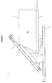
- Figure 1 shows a side view of a freight container tilting apparatus (1) provided in accordance with a preferred embodiment of the present invention.
- the side view of the apparatus (1) shows one of two left and right handed tilting assemblies displaced by the width of a container to be tilted.
- Each assembly includes a tilt arm (2) pivotally mounted on a base section (3) via a pivot connection (4).
- the arm (2) can be tilted relative to the base section (3) by a tilt arm drive (9).
- this pivoting connection (4) of a tilt arm to a base section (3) is located offset from the centre of the tilt arm (2) and displaced from the ends of the tilt arm (2).
- a tilt arm (2) is directly connected to a base section (3) without any intermediate extension arms or additional pivoting connections. This direct coupling of these components allows for a strong robust design which is less likely to fail under load when tilting a container.
- the pivoting connection (4) provides or defines a stationary, fixed pivot point for the tilt arm (2) as the pivot point (4) remains in the same place when the tilt arm (2) is pivoted to tilt an engaged container.
- the height of this pivoting connection (4) above a support surface on which the base section (3) is located is greater than the distance between the pivoting connection (4) and the rear end of the tilt arm (shown to the left hand side of the page). This arrangement of the height of the pivoting connection with respect to its distance from the rear end of the tilt arm allows the tilt arm sufficient ground clearance to pivot an engaged container from an entirely horizontal to an entirely vertical orientation.
- Each tilt arm (2) is formed by a main arm section (2a) which is mounted on a support section (2b).
- the arm section (2a) may be swapped for a different component of a shorter or longer length depending on the length of the container to be tilted.
- a tilt arm (2) Associated with each end of a tilt arm (2) is a set of container locks, being a front container lock (5a) and a rear container lock (5b).
- a front container lock (5a) Associated with each end of a tilt arm (2) is a set of container locks, being a front container lock (5a) and a rear container lock (5b).
- the rear end of the tilt arm (2) is shown at the left hand side of the page in association with the rear container lock (5b).
- the front end of the tilt arm (2) is shown at the right hand side of the page in association with the front container lock (5a).
- the pivoting connection (4) is closer to the rear end of the tilt arm (2) than the front end of the tilt arm.
- each of the base sections (3) act as one of a set of wheel guides which correctly align and position the trailer and associated container (7) as it is backed into the apparatus (1).
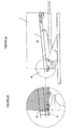
- Figures 3a and 3b show the next stage of this engagement process where the rear end of the tilt arm (2) is orientated downwards to allow the rear container lock (5b) to be engaged with the rear side wall of the container (7).
- the rear container lock incorporates an alignment shaft (5c) and a separate screw clamp (5d).
- the trailer and associated container (7) is backed on to this alignment shaft to correctly position the container within the tilting apparatus (1).
- the screw clamp (5d) is engaged to pull the rear end of the tilt arm (2) into engagement with the rear of the container's side wall.
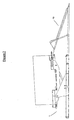
- FIG 4 shows the next stage of the engagement process where the front container locks (5a) are next engaged with the front side wall of the container (7).
- the tilt arm (2) is tilted back in the opposite direction to raise the rear end of the container (7) engaged by the rear container lock (5b) off the bed of the trailer (8).
- a pivoting hook section of the front lock is pivoted into alignment with the side wall of a container (7).
- An L-section bolt then has its short end introduced into a cavity in the front wall of the container with the remaining body of this bolt being threaded through the hook end of the front connector.
- a nut is then threaded onto the free end of the L-section bolt to clamp the pivoting hook surface of the connector into contact with the side wall of the container.
- Figure 6 shows a container tilting apparatus provided in accordance with a further embodiment which can be loaded by a forklift or fork hoist.
- the tilting apparatus (1) illustrated with respect to figure 6 is essentially the same as that disclosed with respect to figures 1 through 5 with the exception of the provision of a recess (9) within the tilt arm (2) shown.
- This recess (9) is provided to allow the tilt apparatus (1) to be loaded with a container or unloaded using a forklift or fork hoist positioned adjacent to and to one side of the apparatus.
- the fork hoist may balance a container on its loading forks and then raise the container up and over the tilt arm shown to position the container within or between the two tilt arms.
- the hoist's forks may then be dropped downwards to position the container side walls between the two tilt arms, allowing the container to be engaged and for the fork hoist's forks to be removed from the recess (9).
- the opposite process may then be completed when the container is to be removed from the tilting apparatus (1).
- Figure 7 shows an alternative loading ramp system used in conjunction with the tilting apparatus illustrated in figure 6 .
- a loading ramp (10) is also provided as part of the tilting apparatus (1). As can be seen from figure 7 this loading ramp may be used to eliminate the need for a stand alone loading dock in some applications.
- the container shown can be unloaded into the tilting apparatus and then the ramp (10) raised to allow material to be loaded via this ramp directly into the interior of the container.
- Figures 8 and 9 show side views of a container tilting apparatus configured in accordance with an additional embodiment which employs a hinged two section tilt arm assembly.
- the tilt apparatus (1) includes a hinged two section tilt arm (20).
- This tilt arm includes a first section (20a) connected by a hinge (11) to a second section (20b).
- the projecting second section (20b) can also be supported using a support post (12) when the arm is positioned in the lowered in the configuration shown with respect to figure 8 .
- the two section tilt arm (20) includes a pair of front container locks (15a, 15b) and a single rear container lock (15c).
- the end of each section (20a, 20b) also employs its own independent door closing mechanism (16a, 16b).
- Figure 8 shows the tilt arm (20) provided in a lowered configuration whereas figure 9 shows the same tilt arm (20) in a raised configuration.
- the tilt arm is also illustrated in an extended configuration where the second section (20b) of the tilt arm is orientated to project out and away from the first section (20a). In this configuration the tilt arm may be used to engage comparatively long containers.
- the tilt arm is lowered onto the support post (12) and a locking system associated with the hinge (11) is released.
- the second section (20b) may then be pivoted back towards the first section until both sections sit adjacent and parallel to one another.
- the second section may then be locked in place in this position and a short length container may subsequently be engaged and lifted.
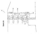
- Figures 10a, 10b and 10c show components of the hinge and hinge locking system employed within the hinged two section tilt arm illustrated with respect to figures 8 and 9 .
- Figures 10a and 10b show more clearly the operation of the hinge system (11) discussed with respect to figures 8 and 9 .
- Figure 10a illustrates the configuration of the hinge when the tilt arm is placed in the arrangement shown with respect to figures 8 and 9 .
- figure 10b illustrates the arrangement of these two arm sections when folded back on one another to engage with a comparatively short container.
- Figures 10a and 10b also show elements of a hinge locking system (13) more clearly illustrated with respect to figure 10c .
- latch elements (13a) are linked to or associated with a drive ram (13b). These latch elements can be driven by the ram to engage with eyelet elements (13c) associated with the opposite tilt arm section. The operation of the drive ram (13b) will then latch or unlatch this locking system to allow or prevent the hinge (11) from being operated.
Claims (13)
- Appareil d'inclinaison de conteneur de fret (1) destiné à incliner un conteneur de fret entre une position horizontale et une position inclinée en vue du chargement ou du déchargement du conteneur, l'appareil comprenant :une section de base (3),des premier et second bras d'inclinaison (2), chacun des bras d'inclinaison étant connecté de façon pivotante à la section de base, et chacun des bras d'inclinaison étant configuré ou configurable pour s'étendre le long de sensiblement toute la longueur du conteneur à incliner, des première et seconde extrémités de chacun des premier et second bras d'inclinaison correspondant à des extrémités opposées du conteneur,un verrou de conteneur (5a, 5b ; 15a, 15b, 15c) au niveau des première et seconde extrémités de chacun des premier et second bras d'inclinaison, chaque verrou de conteneur étant configuré pour engager une extrémité du bras d'inclinaison avec une paroi latérale du conteneur, etau moins un entraînement de bras d'inclinaison (9) configuré pour faire pivoter chaque bras d'inclinaison par rapport à la section de base,dans lequel chaque bras d'inclinaison est connecté directement de façon pivotante à la section de base au niveau d'un point pivot (4) entre les verrous de conteneur au niveau des première et seconde extrémités du bras d'inclinaison et décalé du centre du bras d'inclinaison, et la position du point pivot par rapport à la base est fixe durant l'inclinaison du conteneur ; etla hauteur du point pivot au-dessus d'une surface de support utilisée pour supporter la section de base est supérieure à la distance entre le point pivot et l'extrémité du bras d'inclinaison la plus proche du point pivot.
- Appareil d'inclinaison de conteneur selon la revendication 1, formé à partir d'une paire d'ensembles opposés, chacun consistant en une section de base unique, un bras d'inclinaison et un entraînement de bras d'inclinaison.
- Appareil d'inclinaison de conteneur selon la revendication 2, dans lequel les ensembles opposés de ladite paire d'ensembles opposés sont espacés l'un de l'autre par approximativement la largeur du conteneur à incliner.
- Appareil d'inclinaison de conteneur selon l'une quelconque des revendications précédentes, dans lequel la section de base définit un guide-roues.
- Appareil d'inclinaison de conteneur selon l'une quelconque des revendications précédentes, dans lequel le bras d'inclinaison consiste en une longueur sensiblement droite de matériau actionnable pour être mise en contact avec la majorité d'une paroi latérale du conteneur.
- Appareil d'inclinaison de conteneur selon l'une quelconque des revendications précédentes, dans lequel un évidement est formé dans au moins l'un des bras d'inclinaison pour permettre le chargement latéral du conteneur par un chariot élévateur à fourche ou un palan à fourche.
- Appareil d'inclinaison de conteneur selon l'une quelconque des revendications précédentes, dans lequel le bras d'inclinaison est mis en oeuvre par le biais d'un agencement articulé en deux parties.
- Appareil d'inclinaison de conteneur selon l'une quelconque des revendications précédentes, lequel comporte :les verrous de conteneur avant ou arrière formés à partir d'une section de crochet pivotante disposée sur l'extrémité avant du bras d'inclinaison, et/oules verrous de conteneur avant ou arrière formés, respectivement, à partir d'un arbre d'alignement (5c) et d'une vis de serrage séparée (5d).
- Appareil d'inclinaison de conteneur selon l'une quelconque des revendications précédentes, lequel comporte un indicateur d'angle d'inclinaison et un mécanisme de commande d'angle d'inclinaison.
- Appareil d'inclinaison de conteneur selon l'une quelconque des revendications précédentes, lequel comporte un mécanisme de fermeture de porte (6).
- Appareil d'inclinaison de conteneur selon l'une quelconque des revendications précédentes, dans lequel la section de base comporte un système de vérin configuré pour ajuster la hauteur de la section de base.
- Procédé d'inclinaison d'un conteneur de fret au moyen d'un appareil d'inclinaison de conteneur de fret selon l'une quelconque des revendications précédentes, caractérisé par les étapes suivantes :i) positionnement d'un conteneur de fret entre les deux bras d'inclinaison opposés, etii) inclinaison vers le bas de l'extrémité arrière desdits bras d'inclinaison et vers le haut de l'extrémité avant des bras d'inclinaison, etiii) engagement des extrémités arrière des bras d'inclinaison avec les parois latérales du conteneur de fret au moyen des deux verrous arrière de conteneur, etiv) inclinaison vers le haut des extrémités arrière des bras d'inclinaison et vers le bas des extrémités avant des bras d'inclinaison, etv) engagement des extrémités avant des bras d'inclinaison avec les parois latérales du conteneur de fret au moyen de la paire de verrous avant de conteneur, etiv) levage des extrémités avant des bras d'inclinaison et descente des extrémités arrière des bras d'inclinaison afin d'incliner le conteneur de fret engagé avec les bras d'inclinaison.
- Procédé d'inclinaison d'un conteneur de fret au moyen d'un appareil d'inclinaison de conteneur de fret selon l'une quelconque des revendications 1 à 11, caractérisé par les étapes suivantes :i) positionnement d'un conteneur de fret entre les deux bras d'inclinaison opposés, etii) inclinaison vers le haut des extrémités arrière desdits bras d'inclinaison et vers le bas des extrémités avant des bras d'inclinaison, etiii) engagement des extrémités avant des bras d'inclinaison avec les parois latérales du conteneur de fret au moyen de la paire de verrous avant de conteneur, etiv) inclinaison vers le bas des extrémités arrière des bras d'inclinaison et vers le haut des extrémités avant des bras d'inclinaison, etv) engagement des extrémités arrière des bras d'inclinaison avec les parois latérales du conteneur de fret au moyen des deux verrous arrière de conteneur, etiv) levage des extrémités avant des bras d'inclinaison et descente des extrémités arrière des bras d'inclinaison afin d'incliner le conteneur de fret engagé avec les bras d'inclinaison.
Priority Applications (4)
| Application Number | Priority Date | Filing Date | Title |
|---|---|---|---|
| EP12160427A EP2492223A1 (fr) | 2006-05-26 | 2007-05-25 | Appareil d'inclinaison de conteneurs |
| EP09166835A EP2128053B1 (fr) | 2006-05-26 | 2007-05-25 | Appareil d'inclinaison de conteneurs |
| PL09166835T PL2128053T3 (pl) | 2006-05-26 | 2007-05-25 | Urządzenie do przechylania kontenera |
| DK09166835.0T DK2128053T3 (da) | 2006-05-26 | 2007-05-25 | Containervippeapparat |
Applications Claiming Priority (2)
| Application Number | Priority Date | Filing Date | Title |
|---|---|---|---|
| NZ547544A NZ547544A (en) | 2006-05-26 | 2006-05-26 | Container tilting apparatus |
| PCT/NZ2007/000126 WO2007139398A2 (fr) | 2006-05-26 | 2007-05-25 | Appareil pour incliner des conteneurs |
Related Child Applications (3)
| Application Number | Title | Priority Date | Filing Date |
|---|---|---|---|
| EP12160427A Division EP2492223A1 (fr) | 2006-05-26 | 2007-05-25 | Appareil d'inclinaison de conteneurs |
| EP09166835A Division EP2128053B1 (fr) | 2006-05-26 | 2007-05-25 | Appareil d'inclinaison de conteneurs |
| EP09166835.0 Division-Into | 2009-07-30 |
Publications (3)
| Publication Number | Publication Date |
|---|---|
| EP2021268A2 EP2021268A2 (fr) | 2009-02-11 |
| EP2021268A4 EP2021268A4 (fr) | 2009-11-11 |
| EP2021268B1 true EP2021268B1 (fr) | 2011-05-11 |
Family
ID=38779107
Family Applications (3)
| Application Number | Title | Priority Date | Filing Date |
|---|---|---|---|
| EP07793951A Active EP2021268B1 (fr) | 2006-05-26 | 2007-05-25 | Appareil pour incliner des conteneurs de fret |
| EP12160427A Withdrawn EP2492223A1 (fr) | 2006-05-26 | 2007-05-25 | Appareil d'inclinaison de conteneurs |
| EP09166835A Active EP2128053B1 (fr) | 2006-05-26 | 2007-05-25 | Appareil d'inclinaison de conteneurs |
Family Applications After (2)
| Application Number | Title | Priority Date | Filing Date |
|---|---|---|---|
| EP12160427A Withdrawn EP2492223A1 (fr) | 2006-05-26 | 2007-05-25 | Appareil d'inclinaison de conteneurs |
| EP09166835A Active EP2128053B1 (fr) | 2006-05-26 | 2007-05-25 | Appareil d'inclinaison de conteneurs |
Country Status (13)
| Country | Link |
|---|---|
| US (2) | US8708633B2 (fr) |
| EP (3) | EP2021268B1 (fr) |
| AT (1) | ATE508972T1 (fr) |
| AU (1) | AU2007268365B2 (fr) |
| CA (1) | CA2654173C (fr) |
| DK (1) | DK2128053T3 (fr) |
| ES (1) | ES2401003T3 (fr) |
| MX (1) | MX2008015068A (fr) |
| NZ (1) | NZ547544A (fr) |
| PL (1) | PL2128053T3 (fr) |
| RU (1) | RU2008151384A (fr) |
| WO (1) | WO2007139398A2 (fr) |
| ZA (1) | ZA200810090B (fr) |
Cited By (2)
| Publication number | Priority date | Publication date | Assignee | Title |
|---|---|---|---|---|
| IT201900019994A1 (it) | 2019-10-29 | 2021-04-29 | Gianguido Corvi | Apparecchiatura semovente per la movimentazione di contenitori per trasporto di merci |
| TWI761531B (zh) * | 2018-02-28 | 2022-04-21 | 大陸商蔚來(安徽)控股有限公司 | 升降機 |
Families Citing this family (13)
| Publication number | Priority date | Publication date | Assignee | Title |
|---|---|---|---|---|
| US20100239404A1 (en) * | 2009-03-23 | 2010-09-23 | Bert Joseph Blanchard | Storage and deployment system |
| GB0909120D0 (en) * | 2009-05-28 | 2009-07-01 | Dunn Bros 1995 Ltd | Container loading apparatus |
| US20130177378A1 (en) * | 2010-08-19 | 2013-07-11 | Ahkera Smart Tech Oy | Method and system for the automatic loading of air transport units |
| BR112013022604A2 (pt) * | 2011-03-04 | 2016-12-06 | Rodrigo Graf Fernandez | método e sistema para girar um recipiente, estrutura de viga de reforço ou similares e aparelhos para tal rotação |
| WO2013008211A1 (fr) * | 2011-07-14 | 2013-01-17 | Nortje Gerhard Peter | Appareil et procédé d'inclinaison de contenant |
| CN103196328B (zh) * | 2012-01-10 | 2015-07-22 | 中国人民解放军63908部队 | 组合式炮塔支架 |
| CN105217331A (zh) * | 2014-06-03 | 2016-01-06 | 王同建 | 一种移动式集装箱翻转机 |
| US10399477B2 (en) | 2015-06-26 | 2019-09-03 | Batesville Services, Inc. | Method and apparatus for loading and/or unloading caskets |
| CN104986583A (zh) * | 2015-07-17 | 2015-10-21 | 武汉电力设备厂 | 一种集装箱翻转车 |
| WO2018087529A1 (fr) * | 2016-11-08 | 2018-05-17 | Dunn Bros Machinery Ltd. | Appareil de chargement de conteneur portable, procédé de déploiement dudit appareil et procédé de fonctionnement dudit appareil |
| CN113525207B (zh) * | 2021-06-24 | 2023-03-21 | 中车齐齐哈尔车辆有限公司 | 翻转装置及具有其的车辆 |
| CN113291852B (zh) * | 2021-06-24 | 2022-08-23 | 中车齐齐哈尔车辆有限公司 | 翻转装置 |
| JP2023178116A (ja) * | 2022-06-03 | 2023-12-14 | 株式会社共立物流システム | パレット |
Family Cites Families (33)
| Publication number | Priority date | Publication date | Assignee | Title |
|---|---|---|---|---|
| US375911A (en) * | 1888-01-03 | Apparatus for handling brick | ||
| US2603366A (en) * | 1952-07-15 | Truck unloading apparatus | ||
| US691341A (en) * | 1901-04-17 | 1902-01-14 | Charles Gore | Life-preserver. |
| US2576048A (en) * | 1949-08-18 | 1951-11-20 | Allison Parsons | Truck for handling cylinders of compressed gas or the like |
| US2603501A (en) * | 1950-05-09 | 1952-07-15 | Graves James Renex | Boat trailer |
| US2638236A (en) * | 1950-11-22 | 1953-05-12 | Joseph H Prowinsky | Hand truck |
| US2714461A (en) * | 1953-04-17 | 1955-08-02 | Harry H Walker | Oil drum carrier |
| US2748962A (en) * | 1953-07-17 | 1956-06-05 | Oscar H Murray | Boat trailer |
| US2786586A (en) * | 1953-09-02 | 1957-03-26 | Halver R Straight | Car dumping apparatus |
| US2870928A (en) * | 1955-12-19 | 1959-01-27 | Delphi Products Company Inc | Combination vehicle |
| FR2240883B1 (fr) * | 1973-08-14 | 1977-05-13 | Poirier Jean Claude | |
| DE2450420A1 (de) * | 1974-10-23 | 1976-04-29 | Westerwaelder Eisen Gerhard | Umschlaggeraet zum heben und kippen von frachtcontainern |
| AU498347B2 (en) * | 1974-10-31 | 1979-03-08 | G. F McKENZIE | Container lifting & conveying trailer |
| US4447185A (en) * | 1979-10-11 | 1984-05-08 | Mhlume (Swaziland) Sugar Company Limited | Container tipping apparatus |
| CA1167395A (fr) | 1980-03-14 | 1984-05-15 | Bert Sonnenberg | Bac de stockage autoverseur |
| US4411448A (en) * | 1981-06-17 | 1983-10-25 | Juichiro Takada | Passive type vehicle occupant restraint belt system with electrical braking |
| FI163U1 (fi) | 1992-03-06 | 1992-07-09 | Lindholm Ventola Jukka | Tippanordning |
| GB2269374A (en) * | 1992-08-08 | 1994-02-09 | David Perry | Tilting storage rack for beer barrels |
| GB9425717D0 (en) | 1994-12-20 | 1995-02-22 | Inn Profit Systems Limited | Tilting apparatus |
| DE19523225A1 (de) * | 1995-06-27 | 1997-01-02 | Metallgesellschaft Ag | Vorrichtung zum automatischen Entleeren eines Behälters |
| US5755816A (en) * | 1996-06-21 | 1998-05-26 | Kelley Atlantic Ltd. | Tilt carriage |
| US6027297A (en) * | 1996-12-02 | 2000-02-22 | Dungan; Richard O. | Material handling trailer system |
| FR2785969B1 (fr) | 1998-11-17 | 2001-01-26 | Peugeot | Dispositif de support pour caisse de transport |
| AU759428B2 (en) | 1999-02-08 | 2003-04-17 | Chep Technology Pty Limited | Tilting stand for bulk container |
| WO2001005692A1 (fr) | 1999-07-16 | 2001-01-25 | Taylors Engineering (Blenheim) Limited | Dispositif de vidage d'un receptacle |
| US6394736B1 (en) * | 1999-12-22 | 2002-05-28 | The University Of The State Of New York, State Education Department | Bulk mail container unloading system, apparatus and method |
| CA2293752A1 (fr) | 1999-12-23 | 2001-06-23 | Sylvain Vezina | Systeme de dechargement de blocs de ciment |
| US6913431B2 (en) * | 2001-04-16 | 2005-07-05 | Southworth Products Corporation | Container unloading apparatus |
| BE1014698A6 (nl) * | 2002-03-12 | 2004-03-02 | Eeckhoutte Peter Van | Beweegbaar chassis voor een container. |
| AU2003288889A1 (en) * | 2003-09-30 | 2005-04-14 | Metin Erozlu | A method and system for filling the entire volume of 20 feet steel shipping containers |
| NZ532375A (en) | 2004-04-16 | 2007-08-31 | Nz Express Customs Ltd | Container loader |
| US20070065260A1 (en) * | 2005-08-23 | 2007-03-22 | Chapman Don K | Trailer tipper backstop and safety hoop |
| US8152432B2 (en) | 2008-01-25 | 2012-04-10 | Kylan Cooper | Container unloading device |
-
2006
- 2006-05-26 NZ NZ547544A patent/NZ547544A/en unknown
-
2007
- 2007-05-25 AU AU2007268365A patent/AU2007268365B2/en active Active
- 2007-05-25 MX MX2008015068A patent/MX2008015068A/es active IP Right Grant
- 2007-05-25 EP EP07793951A patent/EP2021268B1/fr active Active
- 2007-05-25 PL PL09166835T patent/PL2128053T3/pl unknown
- 2007-05-25 WO PCT/NZ2007/000126 patent/WO2007139398A2/fr active Application Filing
- 2007-05-25 EP EP12160427A patent/EP2492223A1/fr not_active Withdrawn
- 2007-05-25 ES ES09166835T patent/ES2401003T3/es active Active
- 2007-05-25 DK DK09166835.0T patent/DK2128053T3/da active
- 2007-05-25 RU RU2008151384/11A patent/RU2008151384A/ru unknown
- 2007-05-25 US US12/302,501 patent/US8708633B2/en active Active
- 2007-05-25 EP EP09166835A patent/EP2128053B1/fr active Active
- 2007-05-25 CA CA2654173A patent/CA2654173C/fr active Active
- 2007-05-25 AT AT07793951T patent/ATE508972T1/de not_active IP Right Cessation
-
2008
- 2008-11-26 ZA ZA200810090A patent/ZA200810090B/xx unknown
-
2014
- 2014-04-29 US US14/265,329 patent/US9457969B2/en active Active
Cited By (2)
| Publication number | Priority date | Publication date | Assignee | Title |
|---|---|---|---|---|
| TWI761531B (zh) * | 2018-02-28 | 2022-04-21 | 大陸商蔚來(安徽)控股有限公司 | 升降機 |
| IT201900019994A1 (it) | 2019-10-29 | 2021-04-29 | Gianguido Corvi | Apparecchiatura semovente per la movimentazione di contenitori per trasporto di merci |
Also Published As
| Publication number | Publication date |
|---|---|
| WO2007139398A3 (fr) | 2008-01-24 |
| EP2492223A1 (fr) | 2012-08-29 |
| WO2007139398A2 (fr) | 2007-12-06 |
| EP2128053B1 (fr) | 2013-01-09 |
| PL2128053T3 (pl) | 2013-08-30 |
| DK2128053T3 (da) | 2013-04-15 |
| ATE508972T1 (de) | 2011-05-15 |
| ES2401003T3 (es) | 2013-04-16 |
| EP2021268A4 (fr) | 2009-11-11 |
| AU2007268365B2 (en) | 2013-05-02 |
| EP2021268A2 (fr) | 2009-02-11 |
| RU2008151384A (ru) | 2010-07-10 |
| CA2654173A1 (fr) | 2007-12-06 |
| US20090311081A1 (en) | 2009-12-17 |
| EP2128053A1 (fr) | 2009-12-02 |
| US9457969B2 (en) | 2016-10-04 |
| ZA200810090B (en) | 2009-10-28 |
| CA2654173C (fr) | 2014-05-13 |
| NZ547544A (en) | 2008-05-30 |
| AU2007268365A1 (en) | 2007-12-06 |
| US20150016929A1 (en) | 2015-01-15 |
| US8708633B2 (en) | 2014-04-29 |
| MX2008015068A (es) | 2009-03-05 |
Similar Documents
| Publication | Publication Date | Title |
|---|---|---|
| EP2021268B1 (fr) | Appareil pour incliner des conteneurs de fret | |
| US5391043A (en) | Truck mounted lifting mechanism for lifting and transporting containers | |
| US8152432B2 (en) | Container unloading device | |
| US8226343B2 (en) | Apparatus and methods for loading and transporting containers | |
| US6799935B1 (en) | Lifting apparatus for user in the bed of a pickup truck | |
| KR101495261B1 (ko) | 수직식 리프트 게이트 | |
| CN114194860A (zh) | 一种集装箱运输装卸系统及方法 | |
| US10131264B2 (en) | Hooklift trailer | |
| CN111204593A (zh) | 一种能自动开关箱门的集装箱翻转设备 | |
| US6966741B2 (en) | Tipping apparatus for intermodal container | |
| WO2015011685A2 (fr) | Système de déchargement de conteneur, conteneur et procédé permettant de décharger un tel conteneur | |
| JP3193459U (ja) | テールゲートリフタ装置 | |
| US20120070257A1 (en) | Container loading method and apparatus | |
| GB2472730A (en) | Large container loading | |
| US20090317218A1 (en) | Container tilter | |
| US6027297A (en) | Material handling trailer system | |
| JP4212145B2 (ja) | コンテナ積載用貨物自動車 | |
| JP2016022869A (ja) | テールゲートリフタ装置 | |
| GB2168025A (en) | Handling device | |
| CA2642515C (fr) | Appareillage et methodes de chargement et de transport de conteneurs | |
| KR20240017264A (ko) | 스프레더를 이용한 컨테이너 내용물 하역장치 | |
| KR100836320B1 (ko) | 트럭의 테일 게이트 승하강 장치 | |
| WO2023227825A1 (fr) | Dispositif de manutention de charge pour une unité de transport et unité de transport | |
| KR960003529Y1 (ko) | 화물 차량용 하적장치 | |
| GB2470639A (en) | Large container loading |
Legal Events
| Date | Code | Title | Description |
|---|---|---|---|
| PUAI | Public reference made under article 153(3) epc to a published international application that has entered the european phase |
Free format text: ORIGINAL CODE: 0009012 |
|
| 17P | Request for examination filed |
Effective date: 20081204 |
|
| AK | Designated contracting states |
Kind code of ref document: A2 Designated state(s): AT BE BG CH CY CZ DE DK EE ES FI FR GB GR HU IE IS IT LI LT LU LV MC MT NL PL PT RO SE SI SK TR |
|
| AX | Request for extension of the european patent |
Extension state: AL BA HR MK RS |
|
| RAP1 | Party data changed (applicant data changed or rights of an application transferred) |
Owner name: A WARD ATTACHMENTS LIMITED |
|
| RIN1 | Information on inventor provided before grant (corrected) |
Inventor name: WARD, SIMON ROBERT |
|
| DAX | Request for extension of the european patent (deleted) | ||
| RIC1 | Information provided on ipc code assigned before grant |
Ipc: B66F 9/12 20060101ALI20090828BHEP Ipc: B65G 7/08 20060101ALI20090828BHEP Ipc: B65G 65/23 20060101AFI20080219BHEP Ipc: B65D 88/56 20060101ALI20090828BHEP |
|
| RA4 | Supplementary search report drawn up and despatched (corrected) |
Effective date: 20090915 |
|
| A4 | Supplementary search report drawn up and despatched |
Effective date: 20090915 |
|
| 17Q | First examination report despatched |
Effective date: 20100311 |
|
| RIC1 | Information provided on ipc code assigned before grant |
Ipc: B65D 88/56 20060101ALI20101221BHEP Ipc: B65G 7/08 20060101ALI20101221BHEP Ipc: B65G 65/23 20060101AFI20101221BHEP Ipc: B66F 9/12 20060101ALI20101221BHEP |
|
| RTI1 | Title (correction) |
Free format text: FREIGHT CONTAINER TILTING APPARATUS |
|
| GRAP | Despatch of communication of intention to grant a patent |
Free format text: ORIGINAL CODE: EPIDOSNIGR1 |
|
| GRAS | Grant fee paid |
Free format text: ORIGINAL CODE: EPIDOSNIGR3 |
|
| GRAA | (expected) grant |
Free format text: ORIGINAL CODE: 0009210 |
|
| AK | Designated contracting states |
Kind code of ref document: B1 Designated state(s): AT BE BG CH CY CZ DE DK EE ES FI FR GB GR HU IE IS IT LI LT LU LV MC MT NL PL PT RO SE SI SK TR |
|
| REG | Reference to a national code |
Ref country code: GB Ref legal event code: FG4D |
|
| REG | Reference to a national code |
Ref country code: CH Ref legal event code: EP |
|
| REG | Reference to a national code |
Ref country code: IE Ref legal event code: FG4D |
|
| REG | Reference to a national code |
Ref country code: DE Ref legal event code: R096 Ref document number: 602007014515 Country of ref document: DE Effective date: 20110622 |
|
| REG | Reference to a national code |
Ref country code: NL Ref legal event code: VDEP Effective date: 20110511 |
|
| PG25 | Lapsed in a contracting state [announced via postgrant information from national office to epo] |
Ref country code: PT Free format text: LAPSE BECAUSE OF FAILURE TO SUBMIT A TRANSLATION OF THE DESCRIPTION OR TO PAY THE FEE WITHIN THE PRESCRIBED TIME-LIMIT Effective date: 20110912 Ref country code: LT Free format text: LAPSE BECAUSE OF FAILURE TO SUBMIT A TRANSLATION OF THE DESCRIPTION OR TO PAY THE FEE WITHIN THE PRESCRIBED TIME-LIMIT Effective date: 20110511 Ref country code: SE Free format text: LAPSE BECAUSE OF FAILURE TO SUBMIT A TRANSLATION OF THE DESCRIPTION OR TO PAY THE FEE WITHIN THE PRESCRIBED TIME-LIMIT Effective date: 20110511 |
|
| PG25 | Lapsed in a contracting state [announced via postgrant information from national office to epo] |
Ref country code: GR Free format text: LAPSE BECAUSE OF FAILURE TO SUBMIT A TRANSLATION OF THE DESCRIPTION OR TO PAY THE FEE WITHIN THE PRESCRIBED TIME-LIMIT Effective date: 20110812 Ref country code: BE Free format text: LAPSE BECAUSE OF FAILURE TO SUBMIT A TRANSLATION OF THE DESCRIPTION OR TO PAY THE FEE WITHIN THE PRESCRIBED TIME-LIMIT Effective date: 20110511 Ref country code: CY Free format text: LAPSE BECAUSE OF FAILURE TO SUBMIT A TRANSLATION OF THE DESCRIPTION OR TO PAY THE FEE WITHIN THE PRESCRIBED TIME-LIMIT Effective date: 20110511 Ref country code: IS Free format text: LAPSE BECAUSE OF FAILURE TO SUBMIT A TRANSLATION OF THE DESCRIPTION OR TO PAY THE FEE WITHIN THE PRESCRIBED TIME-LIMIT Effective date: 20110911 Ref country code: FI Free format text: LAPSE BECAUSE OF FAILURE TO SUBMIT A TRANSLATION OF THE DESCRIPTION OR TO PAY THE FEE WITHIN THE PRESCRIBED TIME-LIMIT Effective date: 20110511 Ref country code: AT Free format text: LAPSE BECAUSE OF FAILURE TO SUBMIT A TRANSLATION OF THE DESCRIPTION OR TO PAY THE FEE WITHIN THE PRESCRIBED TIME-LIMIT Effective date: 20110511 Ref country code: SI Free format text: LAPSE BECAUSE OF FAILURE TO SUBMIT A TRANSLATION OF THE DESCRIPTION OR TO PAY THE FEE WITHIN THE PRESCRIBED TIME-LIMIT Effective date: 20110511 Ref country code: LV Free format text: LAPSE BECAUSE OF FAILURE TO SUBMIT A TRANSLATION OF THE DESCRIPTION OR TO PAY THE FEE WITHIN THE PRESCRIBED TIME-LIMIT Effective date: 20110511 Ref country code: ES Free format text: LAPSE BECAUSE OF FAILURE TO SUBMIT A TRANSLATION OF THE DESCRIPTION OR TO PAY THE FEE WITHIN THE PRESCRIBED TIME-LIMIT Effective date: 20110822 |
|
| PG25 | Lapsed in a contracting state [announced via postgrant information from national office to epo] |
Ref country code: MT Free format text: LAPSE BECAUSE OF FAILURE TO SUBMIT A TRANSLATION OF THE DESCRIPTION OR TO PAY THE FEE WITHIN THE PRESCRIBED TIME-LIMIT Effective date: 20110511 Ref country code: MC Free format text: LAPSE BECAUSE OF NON-PAYMENT OF DUE FEES Effective date: 20110531 Ref country code: NL Free format text: LAPSE BECAUSE OF FAILURE TO SUBMIT A TRANSLATION OF THE DESCRIPTION OR TO PAY THE FEE WITHIN THE PRESCRIBED TIME-LIMIT Effective date: 20110511 |
|
| REG | Reference to a national code |
Ref country code: CH Ref legal event code: PL |
|
| PG25 | Lapsed in a contracting state [announced via postgrant information from national office to epo] |
Ref country code: CH Free format text: LAPSE BECAUSE OF NON-PAYMENT OF DUE FEES Effective date: 20110531 Ref country code: LI Free format text: LAPSE BECAUSE OF NON-PAYMENT OF DUE FEES Effective date: 20110531 Ref country code: EE Free format text: LAPSE BECAUSE OF FAILURE TO SUBMIT A TRANSLATION OF THE DESCRIPTION OR TO PAY THE FEE WITHIN THE PRESCRIBED TIME-LIMIT Effective date: 20110511 Ref country code: CZ Free format text: LAPSE BECAUSE OF FAILURE TO SUBMIT A TRANSLATION OF THE DESCRIPTION OR TO PAY THE FEE WITHIN THE PRESCRIBED TIME-LIMIT Effective date: 20110511 |
|
| PG25 | Lapsed in a contracting state [announced via postgrant information from national office to epo] |
Ref country code: SK Free format text: LAPSE BECAUSE OF FAILURE TO SUBMIT A TRANSLATION OF THE DESCRIPTION OR TO PAY THE FEE WITHIN THE PRESCRIBED TIME-LIMIT Effective date: 20110511 Ref country code: RO Free format text: LAPSE BECAUSE OF FAILURE TO SUBMIT A TRANSLATION OF THE DESCRIPTION OR TO PAY THE FEE WITHIN THE PRESCRIBED TIME-LIMIT Effective date: 20110511 Ref country code: DK Free format text: LAPSE BECAUSE OF FAILURE TO SUBMIT A TRANSLATION OF THE DESCRIPTION OR TO PAY THE FEE WITHIN THE PRESCRIBED TIME-LIMIT Effective date: 20110511 Ref country code: PL Free format text: LAPSE BECAUSE OF FAILURE TO SUBMIT A TRANSLATION OF THE DESCRIPTION OR TO PAY THE FEE WITHIN THE PRESCRIBED TIME-LIMIT Effective date: 20110511 |
|
| REG | Reference to a national code |
Ref country code: IE Ref legal event code: MM4A |
|
| PLBE | No opposition filed within time limit |
Free format text: ORIGINAL CODE: 0009261 |
|
| STAA | Information on the status of an ep patent application or granted ep patent |
Free format text: STATUS: NO OPPOSITION FILED WITHIN TIME LIMIT |
|
| 26N | No opposition filed |
Effective date: 20120214 |
|
| PG25 | Lapsed in a contracting state [announced via postgrant information from national office to epo] |
Ref country code: IE Free format text: LAPSE BECAUSE OF NON-PAYMENT OF DUE FEES Effective date: 20110525 |
|
| PG25 | Lapsed in a contracting state [announced via postgrant information from national office to epo] |
Ref country code: IT Free format text: LAPSE BECAUSE OF FAILURE TO SUBMIT A TRANSLATION OF THE DESCRIPTION OR TO PAY THE FEE WITHIN THE PRESCRIBED TIME-LIMIT Effective date: 20110511 |
|
| REG | Reference to a national code |
Ref country code: DE Ref legal event code: R097 Ref document number: 602007014515 Country of ref document: DE Effective date: 20120214 |
|
| PG25 | Lapsed in a contracting state [announced via postgrant information from national office to epo] |
Ref country code: LU Free format text: LAPSE BECAUSE OF NON-PAYMENT OF DUE FEES Effective date: 20110525 |
|
| PG25 | Lapsed in a contracting state [announced via postgrant information from national office to epo] |
Ref country code: BG Free format text: LAPSE BECAUSE OF FAILURE TO SUBMIT A TRANSLATION OF THE DESCRIPTION OR TO PAY THE FEE WITHIN THE PRESCRIBED TIME-LIMIT Effective date: 20110811 |
|
| PG25 | Lapsed in a contracting state [announced via postgrant information from national office to epo] |
Ref country code: TR Free format text: LAPSE BECAUSE OF FAILURE TO SUBMIT A TRANSLATION OF THE DESCRIPTION OR TO PAY THE FEE WITHIN THE PRESCRIBED TIME-LIMIT Effective date: 20110511 |
|
| PG25 | Lapsed in a contracting state [announced via postgrant information from national office to epo] |
Ref country code: HU Free format text: LAPSE BECAUSE OF FAILURE TO SUBMIT A TRANSLATION OF THE DESCRIPTION OR TO PAY THE FEE WITHIN THE PRESCRIBED TIME-LIMIT Effective date: 20110511 |
|
| REG | Reference to a national code |
Ref country code: FR Ref legal event code: PLFP Year of fee payment: 10 |
|
| REG | Reference to a national code |
Ref country code: FR Ref legal event code: PLFP Year of fee payment: 11 |
|
| REG | Reference to a national code |
Ref country code: FR Ref legal event code: PLFP Year of fee payment: 12 |
|
| REG | Reference to a national code |
Ref country code: GB Ref legal event code: S72Z Free format text: COUNTERCLAIM LODGED; COUNTERCLAIM FOR REVOCATION LODGED AT THE INTELLECTUAL PROPERTY ENTERPRISE COURT ON 12 FEBRUARY 2020 (IP-2019-000102) |
|
| REG | Reference to a national code |
Ref country code: GB Ref legal event code: S72Z Free format text: COUNTERCLAIM FOR REVOCATION DISMISSED; COUNTERCLAIM FOR REVOCATION LODGED AT THE INTELLECTUAL PROPERTY ENTERPRISE COURT ON 12 FEBRUARY 2020, DISMISSED BY ORDER OF THE INTELLECTUAL PROPERTY ENTERPRISE COURT ON 1 AUGUST 2021 (IP-2019-000102) |
|
| PGFP | Annual fee paid to national office [announced via postgrant information from national office to epo] |
Ref country code: FR Payment date: 20230525 Year of fee payment: 17 Ref country code: DE Payment date: 20230519 Year of fee payment: 17 |
|
| PGFP | Annual fee paid to national office [announced via postgrant information from national office to epo] |
Ref country code: GB Payment date: 20230517 Year of fee payment: 17 |