EP2019308A2 - Vorrichtung zur spektroskopischen Charakterisierung von an einer Elecktrode gebildeten elektrochemischen Reaktionsprodukten - Google Patents
Vorrichtung zur spektroskopischen Charakterisierung von an einer Elecktrode gebildeten elektrochemischen Reaktionsprodukten Download PDFInfo
- Publication number
- EP2019308A2 EP2019308A2 EP08007799A EP08007799A EP2019308A2 EP 2019308 A2 EP2019308 A2 EP 2019308A2 EP 08007799 A EP08007799 A EP 08007799A EP 08007799 A EP08007799 A EP 08007799A EP 2019308 A2 EP2019308 A2 EP 2019308A2
- Authority
- EP
- European Patent Office
- Prior art keywords
- electrode
- light guide
- mirror
- guide system
- spectroscopic
- Prior art date
- Legal status (The legal status is an assumption and is not a legal conclusion. Google has not performed a legal analysis and makes no representation as to the accuracy of the status listed.)
- Granted
Links
- 238000012512 characterization method Methods 0.000 title claims description 7
- 238000005259 measurement Methods 0.000 claims abstract description 29
- 238000002848 electrochemical method Methods 0.000 claims abstract description 11
- 238000000034 method Methods 0.000 claims description 17
- 238000003487 electrochemical reaction Methods 0.000 claims description 14
- 239000013307 optical fiber Substances 0.000 claims description 8
- 239000007795 chemical reaction product Substances 0.000 claims description 6
- 229910052751 metal Inorganic materials 0.000 claims description 4
- 239000002184 metal Substances 0.000 claims description 4
- 239000012777 electrically insulating material Substances 0.000 claims description 2
- 239000000463 material Substances 0.000 claims description 2
- 239000000047 product Substances 0.000 description 21
- 239000000243 solution Substances 0.000 description 14
- 238000006243 chemical reaction Methods 0.000 description 6
- 239000000543 intermediate Substances 0.000 description 6
- 238000004611 spectroscopical analysis Methods 0.000 description 5
- 239000007858 starting material Substances 0.000 description 4
- 230000005540 biological transmission Effects 0.000 description 3
- 238000001514 detection method Methods 0.000 description 3
- 238000000840 electrochemical analysis Methods 0.000 description 3
- 239000000835 fiber Substances 0.000 description 3
- 230000003595 spectral effect Effects 0.000 description 3
- 238000001228 spectrum Methods 0.000 description 3
- 238000005260 corrosion Methods 0.000 description 2
- 230000007797 corrosion Effects 0.000 description 2
- 238000013461 design Methods 0.000 description 2
- 238000003411 electrode reaction Methods 0.000 description 2
- 239000000203 mixture Substances 0.000 description 2
- BASFCYQUMIYNBI-UHFFFAOYSA-N platinum Chemical compound [Pt] BASFCYQUMIYNBI-UHFFFAOYSA-N 0.000 description 2
- 239000010453 quartz Substances 0.000 description 2
- VYPSYNLAJGMNEJ-UHFFFAOYSA-N silicon dioxide Inorganic materials O=[Si]=O VYPSYNLAJGMNEJ-UHFFFAOYSA-N 0.000 description 2
- 239000000126 substance Substances 0.000 description 2
- 238000002835 absorbance Methods 0.000 description 1
- 229910052782 aluminium Inorganic materials 0.000 description 1
- XAGFODPZIPBFFR-UHFFFAOYSA-N aluminium Chemical compound [Al] XAGFODPZIPBFFR-UHFFFAOYSA-N 0.000 description 1
- 238000013459 approach Methods 0.000 description 1
- 238000004364 calculation method Methods 0.000 description 1
- 239000000919 ceramic Substances 0.000 description 1
- 229920001940 conductive polymer Polymers 0.000 description 1
- 238000011161 development Methods 0.000 description 1
- 238000009792 diffusion process Methods 0.000 description 1
- 239000003792 electrolyte Substances 0.000 description 1
- 238000005516 engineering process Methods 0.000 description 1
- PCHJSUWPFVWCPO-UHFFFAOYSA-N gold Chemical compound [Au] PCHJSUWPFVWCPO-UHFFFAOYSA-N 0.000 description 1
- 229910052737 gold Inorganic materials 0.000 description 1
- 239000010931 gold Substances 0.000 description 1
- 238000007654 immersion Methods 0.000 description 1
- 238000011835 investigation Methods 0.000 description 1
- 238000004519 manufacturing process Methods 0.000 description 1
- 238000001465 metallisation Methods 0.000 description 1
- 238000012986 modification Methods 0.000 description 1
- 230000004048 modification Effects 0.000 description 1
- 230000003287 optical effect Effects 0.000 description 1
- 229910052697 platinum Inorganic materials 0.000 description 1
- 229920000128 polypyrrole Polymers 0.000 description 1
- 239000000523 sample Substances 0.000 description 1
- 230000035945 sensitivity Effects 0.000 description 1
- 229910052709 silver Inorganic materials 0.000 description 1
- 239000004332 silver Substances 0.000 description 1
- 229910001220 stainless steel Inorganic materials 0.000 description 1
- 239000010935 stainless steel Substances 0.000 description 1
- 238000001392 ultraviolet--visible--near infrared spectroscopy Methods 0.000 description 1
Images

Classifications
-
- G—PHYSICS
- G01—MEASURING; TESTING
- G01N—INVESTIGATING OR ANALYSING MATERIALS BY DETERMINING THEIR CHEMICAL OR PHYSICAL PROPERTIES
- G01N21/00—Investigating or analysing materials by the use of optical means, i.e. using sub-millimetre waves, infrared, visible or ultraviolet light
- G01N21/84—Systems specially adapted for particular applications
- G01N21/85—Investigating moving fluids or granular solids
- G01N21/8507—Probe photometers, i.e. with optical measuring part dipped into fluid sample
-
- G—PHYSICS
- G01—MEASURING; TESTING
- G01N—INVESTIGATING OR ANALYSING MATERIALS BY DETERMINING THEIR CHEMICAL OR PHYSICAL PROPERTIES
- G01N21/00—Investigating or analysing materials by the use of optical means, i.e. using sub-millimetre waves, infrared, visible or ultraviolet light
- G01N21/17—Systems in which incident light is modified in accordance with the properties of the material investigated
- G01N21/25—Colour; Spectral properties, i.e. comparison of effect of material on the light at two or more different wavelengths or wavelength bands
- G01N21/31—Investigating relative effect of material at wavelengths characteristic of specific elements or molecules, e.g. atomic absorption spectrometry
-
- G—PHYSICS
- G01—MEASURING; TESTING
- G01N—INVESTIGATING OR ANALYSING MATERIALS BY DETERMINING THEIR CHEMICAL OR PHYSICAL PROPERTIES
- G01N21/00—Investigating or analysing materials by the use of optical means, i.e. using sub-millimetre waves, infrared, visible or ultraviolet light
- G01N21/84—Systems specially adapted for particular applications
- G01N21/85—Investigating moving fluids or granular solids
- G01N21/8507—Probe photometers, i.e. with optical measuring part dipped into fluid sample
- G01N2021/8528—Immerged light conductor
-
- G—PHYSICS
- G01—MEASURING; TESTING
- G01N—INVESTIGATING OR ANALYSING MATERIALS BY DETERMINING THEIR CHEMICAL OR PHYSICAL PROPERTIES
- G01N21/00—Investigating or analysing materials by the use of optical means, i.e. using sub-millimetre waves, infrared, visible or ultraviolet light
- G01N21/17—Systems in which incident light is modified in accordance with the properties of the material investigated
- G01N21/25—Colour; Spectral properties, i.e. comparison of effect of material on the light at two or more different wavelengths or wavelength bands
- G01N21/31—Investigating relative effect of material at wavelengths characteristic of specific elements or molecules, e.g. atomic absorption spectrometry
- G01N21/33—Investigating relative effect of material at wavelengths characteristic of specific elements or molecules, e.g. atomic absorption spectrometry using ultraviolet light
-
- G—PHYSICS
- G01—MEASURING; TESTING
- G01N—INVESTIGATING OR ANALYSING MATERIALS BY DETERMINING THEIR CHEMICAL OR PHYSICAL PROPERTIES
- G01N21/00—Investigating or analysing materials by the use of optical means, i.e. using sub-millimetre waves, infrared, visible or ultraviolet light
- G01N21/17—Systems in which incident light is modified in accordance with the properties of the material investigated
- G01N21/25—Colour; Spectral properties, i.e. comparison of effect of material on the light at two or more different wavelengths or wavelength bands
- G01N21/31—Investigating relative effect of material at wavelengths characteristic of specific elements or molecules, e.g. atomic absorption spectrometry
- G01N21/35—Investigating relative effect of material at wavelengths characteristic of specific elements or molecules, e.g. atomic absorption spectrometry using infrared light
- G01N21/3563—Investigating relative effect of material at wavelengths characteristic of specific elements or molecules, e.g. atomic absorption spectrometry using infrared light for analysing solids; Preparation of samples therefor
Definitions
- the invention relates to a device and a method for the spectroscopic characterization of electrochemical reaction products formed on an electrode.
- the device and method according to the invention enable the spectroscopic characterization of products and intermediates formed by electrochemical reactions on a rotating disc electrode. Such reactions may be the reaction of solutes at the disk electrode or electrochemical reactions of the disk electrode itself, for example corrosion. Furthermore, this method can also be used to characterize subsequent chemical reactions of electrochemically formed products and intermediates.
- spectroelectrochemistry A combined electrochemical and spectroscopic analysis is called spectroelectrochemistry [ AJ Bard, LR Faulkner, Electrochemical Methods, Wiley, New York (2001), p. 680 et seq ]. It is known to use a rotating ring-disc electrode (RRSE) to characterize the products of electrochemical reactions on the rotating disc electrode by means of electrochemical analysis on the ring electrode [ AJ Bard, LR Faulkner, Electrochemical Methods, Wiley, New York (2001), pp. 350 ff ].
- RRSE rotating ring-disc electrode
- a first rotating disc electrode with spectroscopic detection was described by JE McClure [ JE McClure, Analytical Chemistry, 42 (1970) 551f .]. In this arrangement, transmission is measured. The monochromatic measuring light is guided from below to the rotating disk electrode with the aid of a light guide. Around the rotating disk electrode, a bundle of rotating optical fiber fibers is glued, with which the measuring light is guided to a detector, which is separated from the rotating unit by a gap. The problem with this design was the low intensity of the measured signals due to the lock-in technique used. In addition, the rotating optical fiber bundle causes strong noise in the measurement signal.
- the spectroscopic measurement in reflection at an electrode is described in the German patent specification DE 3737489 by H. Meyer et al. described. It is a method to control and control metallization processes by means of a laser beam, which reflects off the surface of an electrode to be coated and the intensity of the reflected beam is measured. The laser beam traverses the entire solution twice. In the case of a rotating disk electrode, the electrochemically formed products are found in sufficient concentration only in a thin layer of a few micrometers in front of the electrode. The method described by H. Meyer would only detect the starting materials spectroscopically due to the long path of the light through the solution. The comparatively thin solution layer containing the products could not be detected spectroscopically. Furthermore a monochromatic laser would be of limited use for spectroscopic analysis. Therefore, the method described by H. Meyer is unsuitable for the purpose of the present invention.
- the known, rotating disk electrode [ AJ Bard, LR Faulkner, Electrochemical Methods, Wiley, New York (2001), p. 335 et seq ] combined with a spectroscopic analysis in the ultraviolet, visible and near infrared spectral range, UV-Vis-NIR.
- the spectroscopic measurement can be carried out with monochromatic or polychromatic light.
- This method allows the spectroscopic characterization of products and intermediates formed by electrochemical reactions on a rotating disc electrode. Such reactions may include the reaction of solutes at the disk electrode or electrochemical reactions of the disk electrode itself, e.g. As corrosion, his. Of Furthermore, this method can also be used to characterize subsequent chemical reactions of electrochemically formed products and intermediates.
- the principle of the known, rotating ring-disk electrode [ AJ Bard, LR Faulkner, Electrochemical Methods, Wiley, New York (2001), pp. 350 ff ], in which the products of electrochemical reactions at the rotating disc electrode are characterized by means of an electrochemical analysis at the ring electrode, further developed and the electrochemical replaced by a spectroscopic analysis.
- the disc and ring electrodes are coaxially mounted on a support and electronically isolated from each other by a dielectric. During operation, the electrodes rotate in the solution, which usually consists of an electrolyte and a substance that is to be characterized electrochemically.
- the rotation of the electrodes results in a defined convection from the solution to the disk electrode and at this radially outward. As a consequence of this, a diffusion layer with a defined layer thickness arises in front of the electrodes.
- These defined mass transport conditions allow the determination of kinetic data and transport quantities from the measured currents as a function of the respective rotational speeds of the rotating disk electrode.
- electrochemical analyzes with the RRSE do not provide information on the structure of the products formed and little information on the composition of product mixtures. This disadvantage of the RRSE is offset by the replacement of the ring electrode by spectroscopic detection. In addition to quantitative determinations, the spectroscopic analysis also allows the elucidation of the structure of the products formed.
- the solution-side end of the light guide system is positioned below the disc electrode or under the mirror.
- annular, electrically insulated mirror is mounted coaxially around the disk electrode and plane-parallel to its bottom surface.
- the mirror is a reflective metal layer or metal plate made of a highly reflective material.
- the mirror can be made of silver, platinum, stainless steel, aluminum or gold.
- the components of the light guide system are housed in a housing and the incidence and reflection angle of the light is 0 ° relative to the perpendicular of the mirror surface.
- the incoming and outgoing light beam is deflected by a total of 180 ° by means of one or more prisms or mirrors and / or by a bend in the light guide system.
- the apparatus cost of the device according to the invention is also so low because the optical fiber system is immersed in the solution to be examined from above. This makes flexible use possible even with existing measuring cells or containers.
- the optical fiber system can be positioned manually or by motor in the x-direction and z-direction with the aid of a positioning unit.
- the distance between the light guide system and the mirror can be adjusted and thus the irradiated layer thickness a can be set.
- the simple and user-friendly adjustment of the light guide system using an x, z positioning unit is possible.
- a Haber-Luggin capillary as a reference electrode can be routed along the outside of the light guide system and positioned together with it.
- a constant or variable DC or AC voltage or a constant or variable DC or AC current may be applied to the disc electrode.
- the electrochemical part of the device forms the known rotating disk electrode, which is usually mounted as an exchange electrode on a disk electrode drive.
- the rotating disk electrode can be operated with constant or variable DC or AC voltage or with constant or variable DC or AC.
- a conventional disk electrode drive can be used for the system according to the invention without significant changes.
- the disk electrode however, needs to be modified.
- the disc electrode is coaxial and plane-parallel surrounded by a few millimeters wide, annular mirror.
- the mirror must be electrically isolated from the disc electrode, otherwise electrochemical reactions would take place at the surface of the mirror and falsify the spectroscopic measurement. This can be achieved by an electrically insulating ring, for.
- plastic or ceramic can be realized, which is mounted between the disc electrode and the mirror.
- the distance between disc electrode and annular mirror can be from a few hundred microns to a few millimeters.
- the mirror on which the measuring light is reflected should be embedded flat in order to minimize the noise of the spectroscopic measurement during rotation of the mirror.
- the spectroscopic part of the device consists of two components: the aforementioned rotating mirror, which coaxially surrounds the disk electrode, and a non-rotating optical fiber system which guides the measuring light from a light source to the mirror and resumes the light reflected from the mirror and the detector Directs spectrometer.
- the detector may be, for example, a diode array or a photomultiplier.
- the light guide system consists of at least two, preferably of exactly two, substantially parallel guided beam paths. The incidence and reflection angle is 0 ° relative to the perpendicular of the mirror surface.
- the connection between the light guides which come from the light source or from the spectrometer and the light guide system via corresponding connection options (adapter).
- the incoming and outgoing light beam are deflected by a total of 180 ° with the aid of one or more prisms or mirrors.
- the exiting light beam is directed parallel before entering the solution and the reflected light beam is focused onto the inlet opening of the light guide.
- the light passes twice through the solution between the light guide system and the mirror. This increases the measuring sensitivity.
- the structure of the light guide system is similar to the structure of known immersion probes, as they are for example in DE 9319750 U1 describe is. Unlike these, however, the mirror that reflects the measuring light is not firmly connected to the light guide system. All components of the fiber optic system are housed in a curved housing.
- the light guide system is mounted on the non-rotating part of the disc electrode drive or on parts of the measuring cell and positioned manually or by motor in the x-direction and z-direction with the aid of a positioning unit.
- the positioning in the z-direction serves to adjust the distance between the light guide system and the mirror in the range of about 1 to 10 mm, which corresponds to an irradiated layer thickness of about 2 to 20 mm. By this adjustment, the ratio of the spectroscopic measurement signals of product and unreacted starting material can be optimized.
- Positioning in the x-direction defines the point at which the light is reflected, so that the reflection conditions and thus the measurement can also be optimized by means of adjustment in the x-direction. The reflection measurement is usually done on the mirror.
- the surface of the disk electrode may also be the surface of the disk electrode.
- layers such as conductive polymers such as polypyrrole, which have formed as a result of electrochemical reactions on the disk electrode, are investigated.
- the light guide system is positioned under the disc electrode so that the measuring beam is reflected at the edge of the disc electrode. After recording one or more spectra, the light guide system is displaced by a defined distance along the diagonal in the direction of the opposite edge of the disc electrode in order again to record one or more spectra. The repetition of this process along the entire diagonal of the disk electrode provides a spatially resolved spectroscopic image of the surface of the disk electrode.
- the spectroscopic measurement can be carried out with a rotating or stationary disk electrode.
- the device described above is further characterized by the following advantages:
- the invention described here replaces the previously used, spectroscopic determination of the products formed on a rotating disk electrode in transmission by a reflection measurement and uses optical fiber technology for this purpose.
- the main advantages compared to the devices mentioned lie in the significant simplification of the entire measuring arrangement and in the adjustability of the thickness of the irradiated layer.
- no complex and costly modification of existing disk electrode drives is required.
- These can easily be retrofitted with the light guide and positioning system.
- the light guide system is inserted into the measuring cell from the top so that no or only minor changes to the measuring cell are required.
- the light guide system can be coupled to a variety of commercially available light sources and spectrometers, or detector systems.
- the cell structure and the positioning of the capillary can be simplified by mounting the capillary on the outside of the light guide system and positioning it together with it.
- a further innovation is the possibility, in addition to the spectroscopic measurement of the products in the vicinity of the disk electrode, also changes on the disk electrode itself, which occur as a result of electrochemical reactions. be detected spectroscopically.
- the light guide system can also be positioned directly under the rotating disc electrode.
- the device according to the invention allows the spectroscopic identification of electrochemically formed products and intermediates and any chemical derived products on the basis of the position and shape of characteristic bands as well as on the basis of the respective rotational speed of a rotating disc electrode and of the applied voltage or of the applied current at this disc electrode for a calibration also the quantitative determination of the mentioned products on the basis of the intensity of the bands at certain wavelengths.
- the half-lives of unstable intermediates can be determined by varying the mentioned parameters.
- the system according to the invention is very suitable for kinetic and mechanistic investigations.
- the light guide system fundamentally disturbs the flow conditions in front of the rotating disk electrode. Due to its small diameter of about 6 mm, this disturbance is low.
- the Haber-Luggin capillary of the reference electrode must be positioned under the rotating disc electrode. In order to simplify the cell structure and facilitate the adjustment, this capillary can be mounted on the outside of the light guide system and positioned together with it.
- the device according to the invention can be used particularly advantageously for a method for the spectroscopic determination of the reaction products formed on a rotating disk electrode, the spectroscopic measurement taking place in reflection and the layer thickness irradiated thereby being adjustable.
- a method for the spectroscopic determination of the reaction products formed on a rotating disk electrode the spectroscopic measurement taking place in reflection and the layer thickness irradiated thereby being adjustable.
- Such a method is also an object of the present invention.
- the spectroscopic reflection measurement can also be carried out in a spatially resolved manner on the rotating disk electrode with the aid of the positioning system.
- a rotating ring disk electrode is used and the spectroscopic measurement then takes place in reflection on the electroless ring electrode.
- the position at which the reflection of the measuring light takes place can be adjusted with the aid of a positioning system.
- the positioning system With the help of the positioning system, the distance between the light guide system and the mirror adjusted and thus the thickness of the irradiated layer can be adjusted.
- the spectroscopic measurement can be carried out with a rotating or stationary disk electrode.
- the spectroscopic measurement can be carried out with monochromatic or polychromatic light in the ultraviolet, visible and near infrared spectral range.
- a constant or variable DC or AC voltage or a constant or variable DC or AC current can be applied to the rotating disc electrode.
- the electrochemically formed products can be qualitatively and quantitatively characterized.
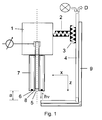
- Fig. 1 schematically shows a cross section of the system according to the invention, consisting of a disk electrode drive 1 with pantograph, a positioning with a positioning system in the x-direction 2 and a positioning system in the z-direction 3, a light guide system 4, a rotating disk electrode 5 and the rotating shroud 7 of the disk electrode 5 with the attached rotating annular mirror 6.
- the rotating disk electrode 5 is used as a working electrode.
- the measuring cell and a counter electrode of any kind is not shown in the drawing.
- the two arrows marked hv show the path of the light from the light guide system to the mirror and, after the reflection at the mirror, back to the light guide system.
- the irradiated layer thickness a is marked accordingly.
- the light is guided by a light source into the light guide system and leaves the light guide system in the direction of a detector D of a spectrometer.
- a Haber-Luggin capillary 9 may be connected to the fiber optic system for any reference electrode.
- the lower part of the rotating disk electrode and the optical fiber system immerse during the measurement in a solution not shown in the drawing.
- the absorbance is a spectroscopic reference measurement, i. H. the inclusion of a spectrum without electrochemical products required. This can be done in a measurement in that no current flows during the reference measurement on the disk electrode and thus no products are formed.
- Fig. 2 shows a bottom view of the modified with an annular mirror 6, rotating disk electrode 5. Between the mirror and the disk electrode is a ring 8 of electrically insulating material.
Landscapes
- Physics & Mathematics (AREA)
- Biochemistry (AREA)
- Health & Medical Sciences (AREA)
- Life Sciences & Earth Sciences (AREA)
- Chemical & Material Sciences (AREA)
- Analytical Chemistry (AREA)
- Spectroscopy & Molecular Physics (AREA)
- General Health & Medical Sciences (AREA)
- General Physics & Mathematics (AREA)
- Immunology (AREA)
- Pathology (AREA)
- Investigating Or Analysing Materials By Optical Means (AREA)
- Investigating, Analyzing Materials By Fluorescence Or Luminescence (AREA)
- Optical Measuring Cells (AREA)
Abstract
Description
- Gegenstand der Erfindung ist eine Vorrichtung und ein Verfahren zur spektroskopischen Charakterisierung von an einer Elektrode gebildeten elektrochemischen Reaktionsprodukten. Die erfindungsgemäße Vorrichtung und Methode ermöglicht die spektroskopische Charakterisierung von Produkten und Zwischenprodukten, die durch elektrochemische Reaktionen an einer rotierenden Scheibenelektrode gebildet wurden. Solche Reaktionen können die Umsetzung von gelösten Stoffen an der Scheibenelektrode oder elektrochemische Reaktionen der Scheibenelektrode selbst, beispielsweise Korrosion, sein. Des Weiteren können mit dieser Methode auch chemische Folgereaktionen von elektrochemisch gebildeten Produkten und Zwischenprodukten charakterisiert werden.
- Eine kombinierte elektrochemische und spektroskopische Analyse wird als Spektroelektrochemie bezeichnet [A. J. Bard, L. R. Faulkner, Electrochemical Methods, Wiley, New York (2001), S. 680 ff]. Es ist bekannt, eine rotierende Ring-Scheiben-Elektrode (RRSE) zu verwenden, um die Produkte elektrochemischer Reaktionen an der rotierenden Scheibenelektrode mit Hilfe einer elektrochemischen Analyse an der Ringelektrode zu charakterisieren [A. J. Bard, L. R. Faulkner, Electrochemical Methods, Wiley, New York (2001), S. 350 ff].
- Eine erste rotierende Scheibenelektrode mit spektroskopischer Detektion wurde von J. E. McClure beschrieben [J. E. McClure, Analytical Chemistry, 42 (1970) 551f.]. Bei dieser Anordnung wird in Transmission gemessen. Das monochromatische Messlicht wird mit Hilfe eines Lichtleiters von unten an die rotierende Scheibenelektrode herangeführt. Um die rotierende Scheibenelektrode herum wird ein Bündel aus rotierenden Lichtleiterfasern geklebt, mit denen das Messlicht zu einem Detektor, der von der rotierenden Einheit durch einen Spalt getrennt ist, geführt wird. Problematisch bei dieser Ausführung war die geringe Intensität der gemessenen Signale aufgrund der verwendeten Lock-in-Technik. Außerdem verursacht das rotierende Lichtleiterbündel starkes Rauschen im Messsignal.
- In der deutschen Patentschrift
DE 2735247 wurde der Ansatz, die Reaktionsprodukte in Transmisson zu messen, von K. Heusler aufgegriffen und durch die Verwendung einer Ringleuchte, die das Messlicht von unten an die rotierende Scheibenelektrode heranführt, sowie einer veränderten Lichtführung an der Scheibenelektrode weiterentwickelt. In der Mitte der Ringleuchte befindet sich eine kreisförmige Aussparung, um die Strömung zur rotierenden Scheibenelektrode nicht zu unterbrechen. Die Scheibenelektrode ist von einem Quarzring umgeben, der über der Ringleuchte angeordnet ist. Nachdem das Messlicht ausgehend von der Ringleuchte die Lösung und den Quarzring durchquert hat, wird es von einem ringförmigen Empfänger zu einem Lichtleiter und schließlich zum Detektor geführt. Der Strahlengang wird durch zwei Blenden an der Ringleuchte und am Empfänger begrenzt. Obgleich mit diesem System einige elektrochemische Reaktionen qualitativ und quantitativ charakterisiert werden konnten [H. Debrodt, Dissertation, Clausthal (1978)], wurde es kommerziell nicht umgesetzt. Die Ursachen hierfür dürften in der komplizierten und zeitaufwändigen Justierung von Ringleuchte und Empfänger sowie dem konstruktiv aufwändigen Design der gesamten Messzelle und den damit verbundenen hohen Herstellungskosten liegen. Des Weiteren ist die kanalartige Strömungsführung zur Scheibenelektrode durch die Aussparung der Ringleuchte, durch die zusätzlich noch die Haber-Luggin-Kapillare der Bezugselektrode geführt wird, ungünstig. Außerdem kann mit den Vorrichtungen nach Heusler und nach McClure die Dicke der durchstrahlten Schicht nicht verändert werden, was bei hohen Konzentrationen an Ausgangsstoffen nachteilig ist. - Die spektroskopische Messung in Reflexion an einer Elektrode wird in der deutschen Patentschrift
DE 3737489 von H. Meyer et al. beschrieben. Dabei handelt es sich um ein Verfahren zur Kontrolle und Steuerung von Metallisierungsprozessen mit Hilfe eines Laserstrahles, der von der Oberfläche einer zu beschichtenden Elektrode reflektiert und die Intensität des reflektierten Strahles gemessen wird. Der Laserstrahl durchquert die gesamte Lösung zweimal. Im Falle einer rotierenden Scheibenelektrode findet man die elektrochemisch gebildeten Produkte in ausreichender Konzentration nur in einer dünnen Schicht von wenigen Mikrometern vor der Elektrode. Das von H. Meyer beschriebene Verfahren würde aufgrund des langen Weges des Lichtes durch die Lösung nur die Ausgangsstoffe spektroskopisch erfassen. Die vergleichsweise dünne Lösungs-Schicht, die die Produkte enthält, könnte spektroskopisch nicht erfasst werden. Außerdem wäre ein monochromatischer Laser für spektroskopische Analysen nur sehr eingeschränkt nutzbar. Deshalb ist das von H. Meyer beschriebene Verfahren für den Einsatzzweck der vorliegenden Erfindung ungeeignet. - Es stellte sich somit die Aufgabe, eine alternative Apparatur mit einfachem Aufbau und flexiblen Einsatzmöglichkeiten für die qualitative und quantitative Charakterisierung elektrochemischer Reaktionen bereitzustellen.
- Die Aufgabe wurde durch eine Vorrichtung zur spektroskopischen Charakterisierung von an einer Elektrode gebildeten elektrochemischen Reaktionsprodukten gelöst, wobei die Vorrichtung
- zur elektrochemischen Messung eine um ihre Längsachse drehbar gelagerte Scheibenelektrode mit einem Scheibenelektrodenantrieb und
- zur spektroskopischen Reflexionsmessung ein am nicht rotierenden Teil des Scheibenelektrodenantriebs oder an Teilen der Messzelle, vorzugsweise dem Deckel der Zelle, montiertes Lichtleitersystem enthält, wobei das genannte Lichtleitersystem mindestens mit einer Anschlussmöglichkeit für eine Lichtquelle und einer Anschlussmöglichkeit für einen Detektor ausgestattet ist sowie aus mindestens zwei Strahlengängen besteht und die dabei durchstrahlte Schichtdicke a einer zu charakterisierenden Lösung einstellbar ist.
- Dabei wird die bekannte, rotierende Scheibenelektrode [A. J. Bard, L. R. Faulkner, Electrochemical Methods, Wiley, New York (2001), S. 335 ff] mit einer spektroskopischen Analyse im ultravioletten, sichtbaren und nahen infraroten Spektralbereich, UV-Vis-NIR, kombiniert. Die spektroskopische Messung kann mit monochromatischem oder mit polychromatischem Licht durchgeführt werden. Diese Methode ermöglicht die spektroskopische Charakterisierung von Produkten und Zwischenprodukten, die durch elektrochemische Reaktionen an einer rotierenden Scheibenelektrode gebildet wurden. Solche Reaktionen können die Umsetzung von gelösten Stoffen an der Scheibenelektrode oder elektrochemische Reaktionen der Scheibenelektrode selbst, z. B. Korrosion, sein. Des Weiteren können mit dieser Methode auch chemische Folgereaktionen von elektrochemisch gebildeten Produkten und Zwischenprodukten charakterisiert werden.
- Für die vorliegende Erfindung wird das Prinzip der bekannten, rotierenden Ring-Scheiben-Elektrode (RRSE) [A. J. Bard, L. R. Faulkner, Electrochemical Methods, Wiley, New York (2001), S. 350 ff], bei der die Produkte elektrochemischer Reaktionen an der rotierenden Scheibenelektrode mit Hilfe einer elektrochemischen Analyse an der Ringelektrode charakterisiert werden, weiterentwickelt und die elektrochemische durch eine spektroskopische Analyse ersetzt. Bei der RRSE sind die Scheiben- und die Ringelektrode koaxial auf einer Halterung montiert und durch ein Dielektrikum elektronisch voneinander isoliert. Während des Betriebs drehen sich die Elektroden in der Lösung, die in der Regel aus einem Elektrolyten und einem Stoff, der elektrochemisch charakterisiert werden soll, besteht. Aus der Rotation der Elektroden resultiert eine definierte Konvektion aus der Lösung zur Scheibenelektrode und an dieser radial nach außen. Als Folge davon stellt sich eine Diffusionsschicht mit definierter Schichtdicke vor den Elektroden ein. Diese definierten Massentransportbedingungen ermöglichen die Bestimmung von kinetischen Daten und Transportgrößen aus den gemessenen Strömen in Abhängigkeit von den jeweiligen Umdrehungsgeschwindigkeiten der rotierenden Scheibenelektrode. Elektrochemische Analysen mit der RRSE liefern jedoch keine Informationen über die Struktur der gebildeten Produkte und nur wenige Informationen über die Zusammensetzung von Produktgemischen. Dieser Nachteil der RRSE wird durch den Ersatz der Ringelektrode durch eine spektroskopische Detektion aufgehoben. Zusätzlich zu quantitativen Bestimmungen ermöglicht die spektroskopische Analyse auch die Aufklärung der Struktur der gebildeten Produkte.
- Bei einer vorteilhaften Ausgestaltung der Vorrichtung ist das lösungsseitige Ende des Lichtleitersystems unter der Scheibenelektrode oder unter dem Spiegel positioniert.
- Von besonderem Vorteil ist es ferner, wenn im Bodenbereich der Ummantelung der Scheibenelektrode ein ringförmiger, elektrisch isolierter Spiegel koaxial um die Scheibenelektrode herum und planparallel zu deren Bodenfläche angebracht ist.
- Weiterhin ist es von Vorteil, wenn der Spiegel eine reflektierende Metallschicht oder Metallplatte aus einem gut reflektierenden Werkstoff ist. Dabei kann der Spiegel aus Silber, Platin, Edelstahl, Aluminium oder Gold bestehen.
- Im Zuge einer vorteilhaften Weiterentwicklung sind die Komponenten des Lichtleitersystems in einem Gehäuse untergebracht und der Einfalls- und Reflexionswinkel des Lichts beträgt 0° bezogen auf das Lot der Spiegelfläche.
- Ferner ist es von Vorteil, wenn der ein- und austretende Lichtstrahl mit Hilfe eines oder mehrerer Prismen oder Spiegel und/oder durch eine Biegung im Lichtleitersystem jeweils um insgesamt 180° umgelenkt wird. Der apparative Aufwand der erfindungsgemäßen Vorrichtung ist auch deshalb so gering, weil das Lichtleitersystem von oben in die zu untersuchende Lösung eintaucht. Dadurch wird ein flexibler Einsatz auch bei bereits vorhandenen Messzellen oder Behältern möglich.
- Das Lichtleitersystem kann mit Hilfe einer Positioniereinheit manuell oder motorisch in x-Richtung und z-Richtung positioniert werden. Dabei kann insbesondere mit Hilfe dieser Positioniereinheit der Abstand zwischen dem Lichtleitersystem und dem Spiegel justiert und somit die durchstrahlte Schichtdicke a eingestellt werden. Somit ist die einfache und bedienerfreundliche Justierung des Lichtleitersystems mit Hilfe einer x,z-Positioniereinheit möglich. Mit Hilfe der z-Positioniereinheit kann die Dicke der durchstrahlten Lösungs-Schicht eingestellt werden. Diese Einstellungsmöglichkeit ermöglicht die selektive, spektroskopische Erfassung der gebildeten Produkte vor dem Hintergrund der vergleichsweise hohen Konzentration an Ausgangsstoffen in der Lösung durch Positionierung des Lichtleitersystems nahe der rotierenden Scheibenelektrode.
- Für elektrochemische Messungen mit Bezugselektrode kann eine Haber-Luggin-Kapillare als Bezugselektrode außen am Lichtleitersystem entlang geführt und zusammen mit diesem positioniert werden.
- Besondere Flexibilität ergibt sich für die Vorrichtung, wenn die Scheibenelektrode als Wechselelektrode auf dem Scheibenelektrodenantrieb montiert ist.
- Für die spektroskopische Messung kann insbesondere monochromatisches oder polychromatisches Licht im ultravioletten, sichtbaren und nahen infraroten Spektralbereich verwendet werden. Dazu ist eine entsprechende Verbindung zu einer Lichtquelle über die oben genannte Anschlussmöglichkeit des Lichtleitersystems herzustellen.
- An der Scheibenelektrode kann eine konstante oder veränderliche Gleichspannung oder Wechselspannung oder ein konstanter oder veränderlicher Gleichstrom oder Wechselstrom angelegt werden.
- Somit weist die Vorrichtung folgende Komponenten auf: Den elektrochemischen Teil der Vorrichtung bildet die bekannte rotierende Scheibenelektrode, die in der Regel als Wechselelektrode auf einem Scheibenelektrodenantrieb montiert ist. Die rotierende Scheibenelektrode kann mit konstanter oder veränderlicher Gleichspannung oder Wechselspannung oder mit konstantem oder veränderlichem Gleichstrom oder Wechselstrom betrieben werden. Ein konventioneller Scheibenelektrodenantrieb kann für das erfindungsgemäße System ohne wesentliche Veränderungen verwendet werden. Die Scheibenelektrode muss jedoch modifiziert werden. Die Scheibenelektrode ist koaxial und planparallel von einem, einigen Millimetern breiten, ringförmigen Spiegel umgeben. Der Spiegel muss von der Scheibenelektrode elektrisch isoliert sein, da sonst an der Fläche des Spiegels elektrochemische Umsetzungen stattfinden und die spektroskopische Messung verfälschen würden. Dies kann durch einen elektrisch isolierenden Ring, z. B. aus Kunststoff oder Keramik, realisiert werden, der zwischen der Scheibenelektrode und dem Spiegel angebracht wird. Der Abstand zwischen Scheibenelektrode und ringförmigen Spiegel kann von einigen hundert Mikrometern bis zu einigen Millimetern betragen. Der Spiegel, an dem das Messlicht reflektiert wird, sollte plan eingebettet sein, um das Rauschen der spektroskopischen Messung während der Rotation des Spiegels zu minimieren. Alternativ zu diesem Spiegel können auch kommerziell erhältliche, rotierende Ring-Scheibenelektroden verwendet werden. In diesem Fall dient die reflektierende Ringelektrode als Spiegel und wird während der spektroskopischen Messung stromlos gehalten. Dies setzt jedoch einen ausreichenden Reflexionsgrad der Ringelektrode voraus.
- Der spektroskopische Teil der Vorrichtung besteht aus zwei Komponenten: Dem genannten, rotierenden Spiegel, der die Scheibenelektrode koaxial umgibt, und einem nicht rotierenden Lichtleitersystem, das das Messlicht von einer Lichtquelle an den Spiegel führt und das vom Spiegel reflektierte Licht wieder aufnimmt und zum Detektor eines Spektrometers leitet. Der Detektor kann beispielsweise ein Diodenarray oder ein Photomultiplier sein. Dazu besteht das Lichtleitersystem aus mindestens zwei, vorzugsweise aus genau zwei, im Wesentlichen parallel geführten Strahlengängen. Der Einfalls- und Reflexionswinkel beträgt 0° bezogen auf das Lot der Spiegelfläche. Die Verbindung zwischen den Lichtleitern, die von der Lichtquelle oder vom Spektrometer kommen und dem Lichtleitersystem erfolgt über entsprechende Anschlussmöglichkeiten (Adapter). Im Lichtleitersystem werden der ein- und austretende Lichtstrahl mit Hilfe eines oder mehrerer Prismen oder Spiegel jeweils um insgesamt 180° umgelenkt. Der austretende Lichtstrahl wird vor dem Eintritt in die Lösung parallel gerichtet und der reflektierte Lichtstrahl auf die Eintrittsöffnung des Lichtleiters gebündelt. Das Licht durchquert zweimal die Lösung zwischen Lichtleitersystem und Spiegel. Dies erhöht die Messempfindlichkeit. Der Aufbau des Lichtleitersystems ist dem Aufbau von bekannten Tauchsonden ähnlich, wie sie beispielsweise in
DE 9319750 U1 beschreiben ist. Im Gegensatz zu diesen, ist der Spiegel, der das Messlicht reflektiert, jedoch mit dem Lichtleitersystem nicht fest verbunden. Alle Komponenten des Lichtleitersystems sind in einem gebogenen Gehäuse untergebracht. Das Lichtleitersystem wird am nicht rotierenden Teil des Scheibenelektrodenantriebs oder an Teilen der Messzelle montiert und mit Hilfe einer Positioniereinheit manuell oder motorisch in x-Richtung und z-Richtung positioniert. Die Positionierung in z-Richtung dient zur Einstellung des Abstandes zwischen dem Lichtleitersystem und dem Spiegel im Bereich von ca. 1 bis 10 mm, was einer durchstrahlten Schichtdicke von ca. 2 bis 20 mm entspricht. Durch diese Justierung kann das Verhältnis der spektroskopischen Messsignale von Produkt und nicht umgesetzten Ausgangsstoff optimiert werden. Die Positionierung in x-Richtung definiert die Stelle, an der das Licht reflektiert wird, sodass auch mittels Justierung in x-Richtung die Reflexionsbedingungen und damit die Messung optimiert werden kann. Die Reflexionsmessung wird in der Regel am Spiegel erfolgen. Es kann jedoch auch die Oberfläche der Scheibenelektrode sein. Somit könnten auch Schichten, z. B. leitfähige Polymere wie Polypyrrol, die sich in Folge von elektrochemischen Reaktionen auf der Scheibenelektrode gebildet haben, untersucht werden. Mit einer geeigneten Positionierungseinheit, die kleine Schrittweiten in x-Richtung ermöglicht, kann auch ein ortsaufgelöstes, spektroskopisches Profil der Scheibenelektrode erstellt werden. Dazu wird beispielsweise das Lichtleitersystem so unter der Scheibenelektrode positioniert, dass der Messstrahl am Rand der Scheibenelektrode reflektiert wird. Nach Aufnahme eines oder mehrerer Spektren wird das Lichtleitersystem um eine definierte Strecke entlang der Diagonale in Richtung des gegenüberliegenden Randes der Scheibenelektrode verschoben um dort wieder ein oder mehrere Spektren aufzunehmen. Die Wiederholung dieses Ablaufes entlang der gesamten Diagonale der Scheibenelektrode liefert ein ortsaufgelöstes spektroskopisches Abbild der Oberfläche der Scheibenelektrode. Die spektroskopische Messung kann bei rotierender oder stillstehender Scheibenelektrode erfolgen. - Die oben beschrieben Vorrichtung ist weiterhin durch folgende Vorteile gekennzeichnet: Die hier beschriebene Erfindung ersetzt die bisher verwendete, spektroskopische Bestimmung der an einer rotierenden Scheibenelektrode gebildeten Produkte in Transmission durch eine Reflexionsmessung und setzt hierfür Lichtleitertechnik ein. Die wesentlichen Vorteile im Vergleich zu den genannten Vorrichtungen liegen in der deutlichen Vereinfachung der gesamten Messanordnung und in der Einstellbarkeit der Dicke der durchstrahlten Schicht. Im Gegensatz zu den bekannten, in Transmission arbeiteten Systemen ist keine aufwändige und kostenintensive Modifizierung bestehender Scheibenelektrodenantriebe erforderlich. Diese können ohne großen Aufwand mit dem Lichtleiter- und Positioniersystem nachgerüstet werden. Das Lichtleitersystem wird von oben in die Messzelle eingeführt, so dass an der Messzelle keine oder nur geringfügige Veränderungen erforderlich werden. Durch entsprechende Adapter kann das Lichtleitersystem an eine Vielzahl marktgängiger Lichtquellen und Spektrometer, bzw. Detektorsysteme angekoppelt werden. Für elektrochemische Messungen mit Bezugselektrode und Haber-Luggin-Kapillare kann der Zellaufbau und die Positionierung der Kapillare dadurch vereinfacht werden, dass die Kapillare außen am Lichtleitersystem montiert und zusammen mit diesem positioniert wird.
- Eine weitere Neuerung stellt die Möglichkeit dar, zusätzlich zur spektroskopischen Messung der Produkte im Umfeld der Scheibenelektrode nun auch Veränderungen auf der Scheibenelektrode selbst, die sich in Folge elektrochemischer Reaktionen einstellen, spektroskopisch erfasst zu können. Mit Hilfe der x-Positioniereinheit kann das Lichtleitersystem auch direkt unter der rotierenden Scheibenelektrode positioniert werden.
- Die erfindungsgemäße Vorrichtung erlaubt in Abhängigkeit von der jeweiligen Umdrehungsgeschwindigkeit einer rotierenden Scheibenelektrode und von der anliegenden Spannung oder von dem anliegenden Strom an dieser Scheibenelektrode die spektroskopische Identifizierung von elektrochemisch gebildeten Produkten und Zwischenprodukten und eventueller chemischer Folgeprodukte anhand der Lage und Form charakteristischer Banden sowie auf der Basis einer Kalibrierung auch die quantitative Bestimmung der genannten Produkte anhand der Intensität der Banden bei bestimmten Wellenlängen. Außerdem können die Halbwertszeiten instabiler Zwischenprodukte durch Variation der genannten Parameter bestimmt werden. Somit ist das erfindungsgemäße System für kinetische und mechanistische Untersuchungen sehr geeignet.
- Das Lichtleitersystem stört prinzipiell die Strömungsverhältnisse vor der rotierenden Scheibenelektrode. Aufgrund seines kleinen Durchmessers von ca. 6 mm ist diese Störung jedoch gering. Bei elektrochemischen Messungen in Dreielektroden-Technik muss die Haber-Luggin-Kapillare der Bezugselektrode unter der rotierenden Scheibenelektrode positioniert werden. Um den Zellaufbau zu vereinfachen und die Justierung zu erleichtern, kann diese Kapillare außen am Lichtleitersystem montiert und zusammen mit diesem positioniert werden.
- Die erfindungsgemäße Vorrichtung kann besonders vorteilhaft für ein Verfahren zur spektroskopischen Bestimmung der an einer rotierenden Scheibenelektrode gebildeten Reaktionsprodukte verwendet werden, wobei die spektroskopische Messung in Reflexion erfolgt und die dabei durchstrahlte Schichtdicke einstellbar ist. Ein solches Verfahren ist ebenfalls Gegenstand der vorliegenden Erfindung. Dabei ergeben sich insbesondere Vorteile, wenn das Messlicht mit Hilfe eines Lichtleitersystems von einer Lichtquelle zum einem koaxial um die rotierende Scheibenelektrode angebrachten Spiegel und nach der Reflexion am Spiegel über das Lichtleitersystem zu einem Spektrometer oder Detektor geführt wird. Anstelle des Spiegels kann auch auf der rotierenden Scheibenelektrode spektroskopisch in Reflexion gemessen werden.
- Die spektroskopische Reflexionsmessung kann auch an der rotierenden Scheibenelektrode mit Hilfe des Positioniersystems ortsaufgelöst erfolgen.
- Ferner kann es dabei von Vorteil sein, wenn anstelle der durch einen Spiegel modifizierten, rotierenden Scheibenelektrode, eine rotierende Ring-Scheibenelektrode verwendet wird und die spektroskopische Messung dann in Reflexion an der stromlosen Ringelektrode erfolgt.
- Weiterhin ist es von Vorteil, dass mit Hilfe eines Positioniersystems die Position, an der die Reflexion des Messlichtes erfolgt, justiert werden kann. Mit Hilfe des Positioniersystems kann der Abstand zwischen dem Lichtleitersystem und dem Spiegel justiert und damit die Dicke der durchstrahlten Schicht eingestellt werden.
- Die spektroskopische Messung kann bei rotierender oder stillstehender Scheibenelektrode erfolgen.
- Dabei kann die spektroskopische Messung mit monochromatischem oder polychromatischem Licht im ultravioletten, sichtbaren und nahen infraroten Spektralbereich erfolgen.
- An der rotierenden Scheibenelektrode kann eine konstante oder veränderliche Gleichspannung oder Wechselspannung oder ein konstanter oder veränderlicher Gleichstrom oder Wechselstrom angelegt werden.
- Mit Hilfe einer solchen spektroskopischen Reflexions-Messung können die elektrochemisch gebildeten Produkte qualitativ und quantitativ charakterisiert werden.
- Weitere Einzelheiten werden anhand der folgenden Figuren erläutert, wobei
- Fig. 1
- schematisch einen Querschnitt der erfindungsgemäßen Vorrichtung und
- Fig. 2
- eine Ansicht von unten auf die Scheibenelektrode 5 zeigt.
-
Fig. 1 zeigt schematisch einen Querschnitt des erfindungsgemäßen Systems, bestehend aus einem Scheibenelektrodenantrieb 1 mit Stromabnehmer, einer Positioniereinheit mit einem Positioniersystem in x-Richtung 2 und einem Positioniersystem in z-Richtung 3, einem Lichtleitersystem 4, einer rotierenden Scheibenelektrode 5 und der rotierenden Ummantelung 7 der Scheibenelektrode 5 mit dem daran angebrachten rotierenden, ringförmigen Spiegel 6. Die rotierende Scheibenelektrode 5 wird dabei als Arbeitselektrode verwendet. Die Messzelle und eine Gegenelektrode beliebiger Art ist in der Zeichnung nicht dargestellt. - Die beiden mit hv markierten Pfeile zeigen den Weg des Lichtes vom Lichtleitersystem zum Spiegel und nach der Reflexion am Spiegel wieder zurück zum Lichtleitersystem. Die dabei durchstrahlte Schichtdicke a ist entsprechend gekennzeichnet. Das Licht wird von einer Lichtquelle in das Lichtleitersystem geführt und verlässt das Lichtleitersystem in Richtung eines Detektors D eines Spektrometers.
- Mit dem Lichtleitersystem kann, im Falle von elektrochemischen Messungen in Dreielektroden-Technik, eine Haber-Luggin-Kapillare 9 für eine beliebige Bezugselektrode verbunden sein. Der untere Teil der rotierenden Scheibenelektrode und des Lichtleitersystems tauchen während der Messung in eine zeichnerisch nicht dargestellte Lösung ein.
- Für die Berechnung der Extinktion ist eine spektroskopische Referenzmessung, d. h. die Aufnahme eines Spektrums ohne elektrochemische Produkte erforderlich. Dies kann bei einer Messung dadurch erfolgen, dass während der Referenzmessung an der Scheibenelektrode kein Strom fließt und somit auch keine Produkte gebildet werden.
-
Fig. 2 zeigt eine Ansicht von unten auf die mit einem ringförmigen Spiegel 6 modifizierte, rotierende Scheibenelektrode 5. Zwischen dem Spiegel und der Scheibenelektrode befindet sich ein Ring 8 aus elektrisch isolierendem Material.
Claims (15)
- Vorrichtung zur spektroskopischen Charakterisierung von an einer Elektrode gebildeten elektrochemischen Reaktionsprodukten, dadurch gekennzeichnet, dass die Vorrichtung- zur elektrochemischen Messung eine um ihre Längsachse drehbar gelagerte Scheibenelektrode (5) mit einem Scheibenelektrodenantrieb (1) in einer Messzelle und- zur spektroskopischen Reflexionsmessung ein am nicht rotierenden Teil des Scheibenelektrodenantriebs (1) oder an Teilen der Messzelle montiertes Lichtleitersystem (4) enthält, wobei das genannte Lichtleitersystem (4) mindestens mit einer Anschlussmöglichkeit für eine Lichtquelle und einer Anschlussmöglichkeit für einen Detektor (D) ausgestattet ist sowie aus mindestens zwei Strahlengängen besteht und die dabei durchstrahlte Schichtdicke a einer zu charakterisierenden Lösung einstellbar ist.
- Vorrichtung nach Anspruch 1, dadurch gekennzeichnet, dass das lösungsseitige Ende des Lichtleitersystems (4) unter der Scheibenelektrode (5) oder unter dem Spiegel (6) positioniert ist.
- Vorrichtung nach Anspruch 1 oder 2, dadurch gekennzeichnet, dass im Bodenbereich der Ummantelung (7) der Scheibenelektrode (5) ein ringförmiger, elektrisch isolierter Spiegel (6) koaxial um die Scheibenelektrode (5) herum und planparallel zu deren Bodenfläche angebracht ist.
- Vorrichtung nach Anspruch 3, dadurch gekennzeichnet, dass der Spiegel (6) eine reflektierende Metallschicht oder Metallplatte aus einem gut reflektierenden Werkstoff ist.
- Vorrichtung nach einem der Ansprüche 1 bis 4, dadurch gekennzeichnet, dass die Komponenten des Lichtleitersystems (4) in einem Gehäuse untergebracht sind und der Einfalls- und Reflexionswinkel des Lichts 0° bezogen auf das Lot der Spiegelfläche beträgt.
- Vorrichtung nach einem der Ansprüche 1 bis 5, dadurch gekennzeichnet, dass der ein- und austretende Lichtstrahl mit Hilfe eines oder mehrerer Prismen oder Spiegel und/oder durch eine Biegung im Lichtleitersystem (4) jeweils um insgesamt 180° umgelenkt wird.
- Vorrichtung nach einem der Ansprüche 1 bis 6, dadurch gekennzeichnet, dass das Lichtleitersystem (4) von oben in die zu untersuchende Lösung eintaucht.
- Vorrichtung nach einem der Ansprüche 1 bis 7, dadurch gekennzeichnet, dass das Lichtleitersystem (4) mit Hilfe einer Positioniereinheit manuell oder motorisch in x-Richtung und/oder z-Richtung positioniert wird.
- Vorrichtung nach Anspruch 8, dadurch gekennzeichnet, dass mit Hilfe der Positioniereinheit der Abstand zwischen dem Lichtleitersystem (4) und dem Spiegel (6) justiert und somit die durchstrahlte Schichtdicke a eingestellt werden kann.
- Vorrichtung nach einem der Ansprüche 1 bis 9, dadurch gekennzeichnet, dass eine Haber-Luggin-Kapillare (9) als Bezugselektrode außen am Lichtleitersystem (4) entlang geführt und mit diesem positioniert wird.
- Vorrichtung nach einem der Ansprüche 3 bis 10, dadurch gekennzeichnet, dass sich zwischen der Scheibenelektrode (5) und dem Spiegel (6) ein Ring (8) aus elektrisch isolierendem Material befindet.
- Verfahren zur spektroskopischen Bestimmung von an einer rotierenden Scheibenelektrode (5) gebildeten Reaktionsprodukten, dadurch gekennzeichnet, dass die spektroskopische Messung in Reflexion erfolgt und die dabei durchstrahlte Schichtdicke a einstellbar ist.
- Verfahren nach Anspruch 12, dadurch gekennzeichnet, dass ein Messlicht mit Hilfe eines Lichtleitersystems (4) von einer Lichtquelle zu einem koaxial um die rotierende Scheibenelektrode (5) angebrachten Spiegel (6) oder an die rotierende Scheibenelektrode (5) und nach der Reflexion am Spiegel (6) oder an der rotierenden Scheibenelektrode (5) über das Lichtleitersystem (4) zu einem Spektrometer oder Detektor geführt wird.
- Verfahren nach Anspruch 13, dadurch gekennzeichnet, dass die spektroskopische Reflexionsmessung an der rotierenden Scheibenelektrode (5) mit Hilfe eines Positioniersystems ortsaufgelöst erfolgt.
- Verfahren nach Anspruch 13, dadurch gekennzeichnet, dass eine rotierende Ring-Scheibenelektrode ohne Spiegel (6) verwendet wird und die spektroskopische Messung in Reflexion an der stromlosen Ringelektrode erfolgt.
Applications Claiming Priority (1)
| Application Number | Priority Date | Filing Date | Title |
|---|---|---|---|
| DE202007009859U DE202007009859U1 (de) | 2007-07-14 | 2007-07-14 | Vorrichtung zur spektroskopischen Charakterisierung von an einer Elektrode gebildeten elektrochemischen Reaktionsprodukten |
Publications (3)
| Publication Number | Publication Date |
|---|---|
| EP2019308A2 true EP2019308A2 (de) | 2009-01-28 |
| EP2019308A3 EP2019308A3 (de) | 2010-05-05 |
| EP2019308B1 EP2019308B1 (de) | 2011-06-29 |
Family
ID=38622712
Family Applications (1)
| Application Number | Title | Priority Date | Filing Date |
|---|---|---|---|
| EP08007799A Not-in-force EP2019308B1 (de) | 2007-07-14 | 2008-04-23 | Vorrichtung zur spektroskopischen Charakterisierung von an einer Elektrode gebildeten elektrochemischen Reaktionsprodukten |
Country Status (3)
| Country | Link |
|---|---|
| EP (1) | EP2019308B1 (de) |
| AT (1) | ATE514938T1 (de) |
| DE (1) | DE202007009859U1 (de) |
Cited By (3)
| Publication number | Priority date | Publication date | Assignee | Title |
|---|---|---|---|---|
| US9678244B2 (en) | 2015-02-20 | 2017-06-13 | Halliburton Energy Services, Inc. | Thin-layer spectroelectrochemical cell for use in subterranean formation operations |
| US10132959B2 (en) | 2015-02-20 | 2018-11-20 | Halliburton Energy Services, Inc. | Thin-layer spectroelectrochemistry cell and methods for use in subterranean formation operations |
| CN111982991A (zh) * | 2020-08-26 | 2020-11-24 | 广东工业大学 | 一种带有孔的旋转电极装置及电化学测试系统 |
Citations (3)
| Publication number | Priority date | Publication date | Assignee | Title |
|---|---|---|---|---|
| DE2735247A1 (de) | 1977-08-04 | 1979-04-05 | Konrad Prof Dr Heusler | Verfahren zur spektralphotometrischen untersuchung von produkten elektrochemischer reaktionen und vorrichtung zur durchfuehrung des verfahrens |
| DE3737489A1 (de) | 1987-11-02 | 1989-05-18 | Schering Ag | Verfahren zur kontrolle und/oder steuerung von metallisierungsprozessen und vorrichtung hierfuer |
| DE9319750U1 (de) | 1993-12-22 | 1994-02-17 | Hellma GmbH u.Co KG Glastechnische-optische Werkstätten, 79379 Müllheim | Meßvorrichtung, bei welcher ein Lichtstrahl durch ein flüssiges Medium geleitet wird |
-
2007
- 2007-07-14 DE DE202007009859U patent/DE202007009859U1/de not_active Expired - Lifetime
-
2008
- 2008-04-23 AT AT08007799T patent/ATE514938T1/de active
- 2008-04-23 EP EP08007799A patent/EP2019308B1/de not_active Not-in-force
Patent Citations (3)
| Publication number | Priority date | Publication date | Assignee | Title |
|---|---|---|---|---|
| DE2735247A1 (de) | 1977-08-04 | 1979-04-05 | Konrad Prof Dr Heusler | Verfahren zur spektralphotometrischen untersuchung von produkten elektrochemischer reaktionen und vorrichtung zur durchfuehrung des verfahrens |
| DE3737489A1 (de) | 1987-11-02 | 1989-05-18 | Schering Ag | Verfahren zur kontrolle und/oder steuerung von metallisierungsprozessen und vorrichtung hierfuer |
| DE9319750U1 (de) | 1993-12-22 | 1994-02-17 | Hellma GmbH u.Co KG Glastechnische-optische Werkstätten, 79379 Müllheim | Meßvorrichtung, bei welcher ein Lichtstrahl durch ein flüssiges Medium geleitet wird |
Non-Patent Citations (1)
| Title |
|---|
| A. J. BARD; L. R. FAULKNER: "Electrochemical Methods", 2001, WILEY, pages: 335 |
Cited By (4)
| Publication number | Priority date | Publication date | Assignee | Title |
|---|---|---|---|---|
| US9678244B2 (en) | 2015-02-20 | 2017-06-13 | Halliburton Energy Services, Inc. | Thin-layer spectroelectrochemical cell for use in subterranean formation operations |
| US10132959B2 (en) | 2015-02-20 | 2018-11-20 | Halliburton Energy Services, Inc. | Thin-layer spectroelectrochemistry cell and methods for use in subterranean formation operations |
| CN111982991A (zh) * | 2020-08-26 | 2020-11-24 | 广东工业大学 | 一种带有孔的旋转电极装置及电化学测试系统 |
| CN111982991B (zh) * | 2020-08-26 | 2022-04-29 | 广东工业大学 | 一种带有孔的旋转电极装置及电化学测试系统 |
Also Published As
| Publication number | Publication date |
|---|---|
| EP2019308A3 (de) | 2010-05-05 |
| DE202007009859U1 (de) | 2007-10-25 |
| EP2019308B1 (de) | 2011-06-29 |
| ATE514938T1 (de) | 2011-07-15 |
Similar Documents
| Publication | Publication Date | Title |
|---|---|---|
| EP0148497B1 (de) | Vorrichtung zum Führen und Sammeln von Licht in der Fotometrie od. dgl. | |
| EP1068511B1 (de) | Anordnung für die oberflächenplasmonen-resonanz-spektroskopie | |
| DE69423358T2 (de) | Multifunktionales photometer mit beweglicher verbindung zum routing von optischen fasern | |
| DE4042117B4 (de) | Optisches System und Verfahren zur Analyse von Proben | |
| EP0655128B1 (de) | Spektroskopische systeme zur analyse von kleinen und kleinsten substanzmengen | |
| DE69331188T2 (de) | Vorrichtung und verfahren zur molekularen charakterisierung | |
| DE19948587A1 (de) | Spektralphotometrische und nephelometrische Detektionseinheit | |
| DE3531891A1 (de) | Verfahren und vorrichtung zur messung immunologischer reaktionen | |
| DE112007001715B4 (de) | System und Verfahren zur optischen Analyse | |
| DE102017114317A1 (de) | Spektrometrisches Messgerät | |
| WO2001086262A1 (de) | Plasmonenresonanzsensor | |
| EP2652481A2 (de) | Vorrichtung zur photometrischen bzw. spektrometrischen untersuchung einer flüssigen probe | |
| DE102005010681B4 (de) | Messanordnung zum optischen Monitoring von Beschichtungsprozessen | |
| EP2019308B1 (de) | Vorrichtung zur spektroskopischen Charakterisierung von an einer Elektrode gebildeten elektrochemischen Reaktionsprodukten | |
| EP0584654B1 (de) | Verfahren und Vorrichtung zur kontinuierlichen IR-spektroskopischen Analyse hochviskoser Flüssigkeiten mittels abgeschwächter Totalreflexion (ATR) | |
| DE4333560A1 (de) | Vorrichtung zur kontinuierlichen spektroskopischen Analyse nach dem Prinzip der abgeschwächten Totalreflexion | |
| DE3605518A1 (de) | Messzelle fuer die spektrometrie sowie verfahren zum messen der adsorption oder emission einer probe im rohrinnenraum dieser messzelle | |
| DE3112308A1 (de) | Kuevettenanordnung fuer ein spektralphotometer | |
| DE3839561C2 (de) | Vorrichtung zum Bestimmen der Komponenten in flüssigen Medien | |
| DE2201083A1 (de) | Photometer | |
| EP0360150A2 (de) | Vorrichtung zur Bestimmung der effektiven Oberflächenrauhigkeit polierter optischer Proben durch Messung der integralen Streustrahlung | |
| EP0591758A1 (de) | Mehrkomponenten-Analysengerät | |
| EP0997726A2 (de) | Nephelometrische Detektionseinheit mit optischer In-Prozess-Kontrolle | |
| EP3614130A1 (de) | Vorrichtung zur ermittlung optischer eigenschaften von proben | |
| DE19957682A1 (de) | Vorrichtung zur optischen Spektroskopie und Verfahren zu dessen Herstellung |
Legal Events
| Date | Code | Title | Description |
|---|---|---|---|
| PUAI | Public reference made under article 153(3) epc to a published international application that has entered the european phase |
Free format text: ORIGINAL CODE: 0009012 |
|
| AK | Designated contracting states |
Kind code of ref document: A2 Designated state(s): AT BE BG CH CY CZ DE DK EE ES FI FR GB GR HR HU IE IS IT LI LT LU LV MC MT NL NO PL PT RO SE SI SK TR |
|
| AX | Request for extension of the european patent |
Extension state: AL BA MK RS |
|
| PUAL | Search report despatched |
Free format text: ORIGINAL CODE: 0009013 |
|
| AK | Designated contracting states |
Kind code of ref document: A3 Designated state(s): AT BE BG CH CY CZ DE DK EE ES FI FR GB GR HR HU IE IS IT LI LT LU LV MC MT NL NO PL PT RO SE SI SK TR |
|
| AX | Request for extension of the european patent |
Extension state: AL BA MK RS |
|
| RIC1 | Information provided on ipc code assigned before grant |
Ipc: G01N 21/85 20060101ALI20100329BHEP Ipc: G01N 21/31 20060101AFI20080912BHEP |
|
| 17P | Request for examination filed |
Effective date: 20101105 |
|
| AKX | Designation fees paid |
Designated state(s): AT BE BG CH CY CZ DE DK EE ES FI FR GB GR HR HU IE IS IT LI LT LU LV MC MT NL NO PL PT RO SE SI SK TR |
|
| GRAP | Despatch of communication of intention to grant a patent |
Free format text: ORIGINAL CODE: EPIDOSNIGR1 |
|
| RIC1 | Information provided on ipc code assigned before grant |
Ipc: G01N 21/31 20060101AFI20110301BHEP Ipc: G01N 21/85 20060101ALI20110301BHEP |
|
| RTI1 | Title (correction) |
Free format text: DEVICE FOR SPECTROSCOPIC CHARACTERISATION OF ELECTROCHEMICAL REACTIVE PRODUCTS FORMED AT AN ELECTRODE |
|
| GRAS | Grant fee paid |
Free format text: ORIGINAL CODE: EPIDOSNIGR3 |
|
| GRAA | (expected) grant |
Free format text: ORIGINAL CODE: 0009210 |
|
| AK | Designated contracting states |
Kind code of ref document: B1 Designated state(s): AT BE BG CH CY CZ DE DK EE ES FI FR GB GR HR HU IE IS IT LI LT LU LV MC MT NL NO PL PT RO SE SI SK TR |
|
| REG | Reference to a national code |
Ref country code: GB Ref legal event code: FG4D Free format text: NOT ENGLISH |
|
| REG | Reference to a national code |
Ref country code: CH Ref legal event code: EP |
|
| REG | Reference to a national code |
Ref country code: IE Ref legal event code: FG4D Free format text: LANGUAGE OF EP DOCUMENT: GERMAN |
|
| REG | Reference to a national code |
Ref country code: DE Ref legal event code: R096 Ref document number: 502008004007 Country of ref document: DE Effective date: 20110818 |
|
| REG | Reference to a national code |
Ref country code: NL Ref legal event code: VDEP Effective date: 20110629 |
|
| PG25 | Lapsed in a contracting state [announced via postgrant information from national office to epo] |
Ref country code: NO Free format text: LAPSE BECAUSE OF FAILURE TO SUBMIT A TRANSLATION OF THE DESCRIPTION OR TO PAY THE FEE WITHIN THE PRESCRIBED TIME-LIMIT Effective date: 20110929 Ref country code: LT Free format text: LAPSE BECAUSE OF FAILURE TO SUBMIT A TRANSLATION OF THE DESCRIPTION OR TO PAY THE FEE WITHIN THE PRESCRIBED TIME-LIMIT Effective date: 20110629 Ref country code: HR Free format text: LAPSE BECAUSE OF FAILURE TO SUBMIT A TRANSLATION OF THE DESCRIPTION OR TO PAY THE FEE WITHIN THE PRESCRIBED TIME-LIMIT Effective date: 20110629 Ref country code: SE Free format text: LAPSE BECAUSE OF FAILURE TO SUBMIT A TRANSLATION OF THE DESCRIPTION OR TO PAY THE FEE WITHIN THE PRESCRIBED TIME-LIMIT Effective date: 20110629 |
|
| PG25 | Lapsed in a contracting state [announced via postgrant information from national office to epo] |
Ref country code: LV Free format text: LAPSE BECAUSE OF FAILURE TO SUBMIT A TRANSLATION OF THE DESCRIPTION OR TO PAY THE FEE WITHIN THE PRESCRIBED TIME-LIMIT Effective date: 20110629 Ref country code: GR Free format text: LAPSE BECAUSE OF FAILURE TO SUBMIT A TRANSLATION OF THE DESCRIPTION OR TO PAY THE FEE WITHIN THE PRESCRIBED TIME-LIMIT Effective date: 20110930 Ref country code: FI Free format text: LAPSE BECAUSE OF FAILURE TO SUBMIT A TRANSLATION OF THE DESCRIPTION OR TO PAY THE FEE WITHIN THE PRESCRIBED TIME-LIMIT Effective date: 20110629 Ref country code: SI Free format text: LAPSE BECAUSE OF FAILURE TO SUBMIT A TRANSLATION OF THE DESCRIPTION OR TO PAY THE FEE WITHIN THE PRESCRIBED TIME-LIMIT Effective date: 20110629 |
|
| REG | Reference to a national code |
Ref country code: IE Ref legal event code: FD4D |
|
| PG25 | Lapsed in a contracting state [announced via postgrant information from national office to epo] |
Ref country code: NL Free format text: LAPSE BECAUSE OF FAILURE TO SUBMIT A TRANSLATION OF THE DESCRIPTION OR TO PAY THE FEE WITHIN THE PRESCRIBED TIME-LIMIT Effective date: 20110629 Ref country code: PT Free format text: LAPSE BECAUSE OF FAILURE TO SUBMIT A TRANSLATION OF THE DESCRIPTION OR TO PAY THE FEE WITHIN THE PRESCRIBED TIME-LIMIT Effective date: 20111031 Ref country code: EE Free format text: LAPSE BECAUSE OF FAILURE TO SUBMIT A TRANSLATION OF THE DESCRIPTION OR TO PAY THE FEE WITHIN THE PRESCRIBED TIME-LIMIT Effective date: 20110629 Ref country code: CZ Free format text: LAPSE BECAUSE OF FAILURE TO SUBMIT A TRANSLATION OF THE DESCRIPTION OR TO PAY THE FEE WITHIN THE PRESCRIBED TIME-LIMIT Effective date: 20110629 Ref country code: IE Free format text: LAPSE BECAUSE OF FAILURE TO SUBMIT A TRANSLATION OF THE DESCRIPTION OR TO PAY THE FEE WITHIN THE PRESCRIBED TIME-LIMIT Effective date: 20110629 Ref country code: IS Free format text: LAPSE BECAUSE OF FAILURE TO SUBMIT A TRANSLATION OF THE DESCRIPTION OR TO PAY THE FEE WITHIN THE PRESCRIBED TIME-LIMIT Effective date: 20111029 |
|
| PG25 | Lapsed in a contracting state [announced via postgrant information from national office to epo] |
Ref country code: RO Free format text: LAPSE BECAUSE OF FAILURE TO SUBMIT A TRANSLATION OF THE DESCRIPTION OR TO PAY THE FEE WITHIN THE PRESCRIBED TIME-LIMIT Effective date: 20110629 Ref country code: PL Free format text: LAPSE BECAUSE OF FAILURE TO SUBMIT A TRANSLATION OF THE DESCRIPTION OR TO PAY THE FEE WITHIN THE PRESCRIBED TIME-LIMIT Effective date: 20110629 Ref country code: SK Free format text: LAPSE BECAUSE OF FAILURE TO SUBMIT A TRANSLATION OF THE DESCRIPTION OR TO PAY THE FEE WITHIN THE PRESCRIBED TIME-LIMIT Effective date: 20110629 Ref country code: CY Free format text: LAPSE BECAUSE OF FAILURE TO SUBMIT A TRANSLATION OF THE DESCRIPTION OR TO PAY THE FEE WITHIN THE PRESCRIBED TIME-LIMIT Effective date: 20110629 |
|
| PLBE | No opposition filed within time limit |
Free format text: ORIGINAL CODE: 0009261 |
|
| STAA | Information on the status of an ep patent application or granted ep patent |
Free format text: STATUS: NO OPPOSITION FILED WITHIN TIME LIMIT |
|
| PG25 | Lapsed in a contracting state [announced via postgrant information from national office to epo] |
Ref country code: IT Free format text: LAPSE BECAUSE OF FAILURE TO SUBMIT A TRANSLATION OF THE DESCRIPTION OR TO PAY THE FEE WITHIN THE PRESCRIBED TIME-LIMIT Effective date: 20110629 |
|
| 26N | No opposition filed |
Effective date: 20120330 |
|
| PG25 | Lapsed in a contracting state [announced via postgrant information from national office to epo] |
Ref country code: DK Free format text: LAPSE BECAUSE OF FAILURE TO SUBMIT A TRANSLATION OF THE DESCRIPTION OR TO PAY THE FEE WITHIN THE PRESCRIBED TIME-LIMIT Effective date: 20110629 |
|
| REG | Reference to a national code |
Ref country code: DE Ref legal event code: R097 Ref document number: 502008004007 Country of ref document: DE Effective date: 20120330 |
|
| BERE | Be: lapsed |
Owner name: DECHEMA G.- FUR CHEMISCHE TECHNIK UND BIOTECHNOLO Effective date: 20120430 |
|
| PG25 | Lapsed in a contracting state [announced via postgrant information from national office to epo] |
Ref country code: MC Free format text: LAPSE BECAUSE OF NON-PAYMENT OF DUE FEES Effective date: 20120430 |
|
| GBPC | Gb: european patent ceased through non-payment of renewal fee |
Effective date: 20120423 |
|
| REG | Reference to a national code |
Ref country code: FR Ref legal event code: ST Effective date: 20121228 |
|
| PG25 | Lapsed in a contracting state [announced via postgrant information from national office to epo] |
Ref country code: GB Free format text: LAPSE BECAUSE OF NON-PAYMENT OF DUE FEES Effective date: 20120423 Ref country code: BE Free format text: LAPSE BECAUSE OF NON-PAYMENT OF DUE FEES Effective date: 20120430 |
|
| PG25 | Lapsed in a contracting state [announced via postgrant information from national office to epo] |
Ref country code: FR Free format text: LAPSE BECAUSE OF NON-PAYMENT OF DUE FEES Effective date: 20120430 |
|
| PG25 | Lapsed in a contracting state [announced via postgrant information from national office to epo] |
Ref country code: ES Free format text: LAPSE BECAUSE OF FAILURE TO SUBMIT A TRANSLATION OF THE DESCRIPTION OR TO PAY THE FEE WITHIN THE PRESCRIBED TIME-LIMIT Effective date: 20111010 |
|
| PG25 | Lapsed in a contracting state [announced via postgrant information from national office to epo] |
Ref country code: BG Free format text: LAPSE BECAUSE OF FAILURE TO SUBMIT A TRANSLATION OF THE DESCRIPTION OR TO PAY THE FEE WITHIN THE PRESCRIBED TIME-LIMIT Effective date: 20110929 |
|
| PG25 | Lapsed in a contracting state [announced via postgrant information from national office to epo] |
Ref country code: MT Free format text: LAPSE BECAUSE OF FAILURE TO SUBMIT A TRANSLATION OF THE DESCRIPTION OR TO PAY THE FEE WITHIN THE PRESCRIBED TIME-LIMIT Effective date: 20110629 |
|
| PGFP | Annual fee paid to national office [announced via postgrant information from national office to epo] |
Ref country code: DE Payment date: 20130430 Year of fee payment: 6 Ref country code: CH Payment date: 20130429 Year of fee payment: 6 |
|
| PG25 | Lapsed in a contracting state [announced via postgrant information from national office to epo] |
Ref country code: TR Free format text: LAPSE BECAUSE OF FAILURE TO SUBMIT A TRANSLATION OF THE DESCRIPTION OR TO PAY THE FEE WITHIN THE PRESCRIBED TIME-LIMIT Effective date: 20110629 |
|
| PG25 | Lapsed in a contracting state [announced via postgrant information from national office to epo] |
Ref country code: LU Free format text: LAPSE BECAUSE OF NON-PAYMENT OF DUE FEES Effective date: 20120423 |
|
| REG | Reference to a national code |
Ref country code: AT Ref legal event code: MM01 Ref document number: 514938 Country of ref document: AT Kind code of ref document: T Effective date: 20130423 |
|
| PG25 | Lapsed in a contracting state [announced via postgrant information from national office to epo] |
Ref country code: HU Free format text: LAPSE BECAUSE OF FAILURE TO SUBMIT A TRANSLATION OF THE DESCRIPTION OR TO PAY THE FEE WITHIN THE PRESCRIBED TIME-LIMIT Effective date: 20080423 |
|
| PG25 | Lapsed in a contracting state [announced via postgrant information from national office to epo] |
Ref country code: AT Free format text: LAPSE BECAUSE OF NON-PAYMENT OF DUE FEES Effective date: 20130423 |
|
| REG | Reference to a national code |
Ref country code: DE Ref legal event code: R119 Ref document number: 502008004007 Country of ref document: DE |
|
| REG | Reference to a national code |
Ref country code: CH Ref legal event code: PL |
|
| REG | Reference to a national code |
Ref country code: DE Ref legal event code: R119 Ref document number: 502008004007 Country of ref document: DE Effective date: 20141101 |
|
| PG25 | Lapsed in a contracting state [announced via postgrant information from national office to epo] |
Ref country code: LI Free format text: LAPSE BECAUSE OF NON-PAYMENT OF DUE FEES Effective date: 20140430 Ref country code: DE Free format text: LAPSE BECAUSE OF NON-PAYMENT OF DUE FEES Effective date: 20141101 Ref country code: CH Free format text: LAPSE BECAUSE OF NON-PAYMENT OF DUE FEES Effective date: 20140430 |