EP2019247A2 - Verbindungsstruktur für Metall-Harz-Verbindungsröhren und Metall-Harz-Verbindungsröhre zur Verwendung in der Verbindungsstruktur - Google Patents
Verbindungsstruktur für Metall-Harz-Verbindungsröhren und Metall-Harz-Verbindungsröhre zur Verwendung in der Verbindungsstruktur Download PDFInfo
- Publication number
- EP2019247A2 EP2019247A2 EP08160207A EP08160207A EP2019247A2 EP 2019247 A2 EP2019247 A2 EP 2019247A2 EP 08160207 A EP08160207 A EP 08160207A EP 08160207 A EP08160207 A EP 08160207A EP 2019247 A2 EP2019247 A2 EP 2019247A2
- Authority
- EP
- European Patent Office
- Prior art keywords
- diameter
- metal
- resin composite
- tubular member
- attached
- Prior art date
- Legal status (The legal status is an assumption and is not a legal conclusion. Google has not performed a legal analysis and makes no representation as to the accuracy of the status listed.)
- Withdrawn
Links
- 239000000805 composite resin Substances 0.000 title claims abstract description 73
- 230000003014 reinforcing effect Effects 0.000 claims abstract description 45
- 238000007789 sealing Methods 0.000 claims abstract description 32
- 229920003002 synthetic resin Polymers 0.000 claims description 21
- 239000000057 synthetic resin Substances 0.000 claims description 21
- 239000002184 metal Substances 0.000 claims description 12
- 229910052751 metal Inorganic materials 0.000 claims description 12
- 239000000463 material Substances 0.000 description 7
- 238000012856 packing Methods 0.000 description 7
- 230000002093 peripheral effect Effects 0.000 description 5
- XLYOFNOQVPJJNP-UHFFFAOYSA-N water Substances O XLYOFNOQVPJJNP-UHFFFAOYSA-N 0.000 description 5
- 229910000831 Steel Inorganic materials 0.000 description 4
- 229920005989 resin Polymers 0.000 description 4
- 239000011347 resin Substances 0.000 description 4
- 239000010959 steel Substances 0.000 description 4
- 238000004804 winding Methods 0.000 description 4
- 238000001125 extrusion Methods 0.000 description 3
- 238000001764 infiltration Methods 0.000 description 3
- 230000008595 infiltration Effects 0.000 description 3
- 238000000465 moulding Methods 0.000 description 3
- 229920003051 synthetic elastomer Polymers 0.000 description 3
- 239000013585 weight reducing agent Substances 0.000 description 3
- XEEYBQQBJWHFJM-UHFFFAOYSA-N Iron Chemical compound [Fe] XEEYBQQBJWHFJM-UHFFFAOYSA-N 0.000 description 2
- 239000011248 coating agent Substances 0.000 description 2
- 238000000576 coating method Methods 0.000 description 2
- 238000010276 construction Methods 0.000 description 2
- 239000012530 fluid Substances 0.000 description 2
- 229920003052 natural elastomer Polymers 0.000 description 2
- 229920001194 natural rubber Polymers 0.000 description 2
- 239000003566 sealing material Substances 0.000 description 2
- 239000010865 sewage Substances 0.000 description 2
- 239000005061 synthetic rubber Substances 0.000 description 2
- 238000003466 welding Methods 0.000 description 2
- 244000043261 Hevea brasiliensis Species 0.000 description 1
- 229920000459 Nitrile rubber Polymers 0.000 description 1
- 229920005830 Polyurethane Foam Polymers 0.000 description 1
- 229920006311 Urethane elastomer Polymers 0.000 description 1
- 239000000853 adhesive Substances 0.000 description 1
- 230000001070 adhesive effect Effects 0.000 description 1
- 229920005549 butyl rubber Polymers 0.000 description 1
- 239000003795 chemical substances by application Substances 0.000 description 1
- 235000009508 confectionery Nutrition 0.000 description 1
- 238000000151 deposition Methods 0.000 description 1
- 229920001971 elastomer Polymers 0.000 description 1
- 239000000806 elastomer Substances 0.000 description 1
- 238000001914 filtration Methods 0.000 description 1
- 238000005187 foaming Methods 0.000 description 1
- 238000001746 injection moulding Methods 0.000 description 1
- 229910052742 iron Inorganic materials 0.000 description 1
- 238000005304 joining Methods 0.000 description 1
- 239000007788 liquid Substances 0.000 description 1
- 238000004519 manufacturing process Methods 0.000 description 1
- 238000000034 method Methods 0.000 description 1
- 229920013716 polyethylene resin Polymers 0.000 description 1
- 229920005672 polyolefin resin Polymers 0.000 description 1
- 229920001296 polysiloxane Polymers 0.000 description 1
- 239000011496 polyurethane foam Substances 0.000 description 1
- 239000004800 polyvinyl chloride Substances 0.000 description 1
- 229920000915 polyvinyl chloride Polymers 0.000 description 1
- 239000005060 rubber Substances 0.000 description 1
- 229920003048 styrene butadiene rubber Polymers 0.000 description 1
- 229920002725 thermoplastic elastomer Polymers 0.000 description 1
- 125000000391 vinyl group Chemical group [H]C([*])=C([H])[H] 0.000 description 1
- 229920002554 vinyl polymer Polymers 0.000 description 1
Images


Classifications
-
- F—MECHANICAL ENGINEERING; LIGHTING; HEATING; WEAPONS; BLASTING
- F16—ENGINEERING ELEMENTS AND UNITS; GENERAL MEASURES FOR PRODUCING AND MAINTAINING EFFECTIVE FUNCTIONING OF MACHINES OR INSTALLATIONS; THERMAL INSULATION IN GENERAL
- F16L—PIPES; JOINTS OR FITTINGS FOR PIPES; SUPPORTS FOR PIPES, CABLES OR PROTECTIVE TUBING; MEANS FOR THERMAL INSULATION IN GENERAL
- F16L9/00—Rigid pipes
- F16L9/14—Compound tubes, i.e. made of materials not wholly covered by any one of the preceding groups
- F16L9/147—Compound tubes, i.e. made of materials not wholly covered by any one of the preceding groups comprising only layers of metal and plastics with or without reinforcement
-
- F—MECHANICAL ENGINEERING; LIGHTING; HEATING; WEAPONS; BLASTING
- F16—ENGINEERING ELEMENTS AND UNITS; GENERAL MEASURES FOR PRODUCING AND MAINTAINING EFFECTIVE FUNCTIONING OF MACHINES OR INSTALLATIONS; THERMAL INSULATION IN GENERAL
- F16L—PIPES; JOINTS OR FITTINGS FOR PIPES; SUPPORTS FOR PIPES, CABLES OR PROTECTIVE TUBING; MEANS FOR THERMAL INSULATION IN GENERAL
- F16L47/00—Connecting arrangements or other fittings specially adapted to be made of plastics or to be used with pipes made of plastics
- F16L47/26—Connecting arrangements or other fittings specially adapted to be made of plastics or to be used with pipes made of plastics for branching pipes; for joining pipes to walls; Adaptors therefor
- F16L47/28—Joining pipes to walls or to other pipes, the axis of the joined pipe being perpendicular to the wall or to the axis of the other pipe
- F16L47/30—Joining pipes to walls or to other pipes, the axis of the joined pipe being perpendicular to the wall or to the axis of the other pipe using attaching means embracing the pipe
-
- F—MECHANICAL ENGINEERING; LIGHTING; HEATING; WEAPONS; BLASTING
- F16—ENGINEERING ELEMENTS AND UNITS; GENERAL MEASURES FOR PRODUCING AND MAINTAINING EFFECTIVE FUNCTIONING OF MACHINES OR INSTALLATIONS; THERMAL INSULATION IN GENERAL
- F16L—PIPES; JOINTS OR FITTINGS FOR PIPES; SUPPORTS FOR PIPES, CABLES OR PROTECTIVE TUBING; MEANS FOR THERMAL INSULATION IN GENERAL
- F16L11/00—Hoses, i.e. flexible pipes
- F16L11/14—Hoses, i.e. flexible pipes made of rigid material, e.g. metal or hard plastics
- F16L11/15—Hoses, i.e. flexible pipes made of rigid material, e.g. metal or hard plastics corrugated
-
- F—MECHANICAL ENGINEERING; LIGHTING; HEATING; WEAPONS; BLASTING
- F16—ENGINEERING ELEMENTS AND UNITS; GENERAL MEASURES FOR PRODUCING AND MAINTAINING EFFECTIVE FUNCTIONING OF MACHINES OR INSTALLATIONS; THERMAL INSULATION IN GENERAL
- F16L—PIPES; JOINTS OR FITTINGS FOR PIPES; SUPPORTS FOR PIPES, CABLES OR PROTECTIVE TUBING; MEANS FOR THERMAL INSULATION IN GENERAL
- F16L21/00—Joints with sleeve or socket
- F16L21/02—Joints with sleeve or socket with elastic sealing rings between pipe and sleeve or between pipe and socket, e.g. with rolling or other prefabricated profiled rings
-
- F—MECHANICAL ENGINEERING; LIGHTING; HEATING; WEAPONS; BLASTING
- F16—ENGINEERING ELEMENTS AND UNITS; GENERAL MEASURES FOR PRODUCING AND MAINTAINING EFFECTIVE FUNCTIONING OF MACHINES OR INSTALLATIONS; THERMAL INSULATION IN GENERAL
- F16L—PIPES; JOINTS OR FITTINGS FOR PIPES; SUPPORTS FOR PIPES, CABLES OR PROTECTIVE TUBING; MEANS FOR THERMAL INSULATION IN GENERAL
- F16L25/00—Construction or details of pipe joints not provided for in, or of interest apart from, groups F16L13/00 - F16L23/00
- F16L25/0036—Joints for corrugated pipes
- F16L25/0063—Joints for corrugated pipes with two corrugated pipes being directly connected to each other
-
- F—MECHANICAL ENGINEERING; LIGHTING; HEATING; WEAPONS; BLASTING
- F16—ENGINEERING ELEMENTS AND UNITS; GENERAL MEASURES FOR PRODUCING AND MAINTAINING EFFECTIVE FUNCTIONING OF MACHINES OR INSTALLATIONS; THERMAL INSULATION IN GENERAL
- F16L—PIPES; JOINTS OR FITTINGS FOR PIPES; SUPPORTS FOR PIPES, CABLES OR PROTECTIVE TUBING; MEANS FOR THERMAL INSULATION IN GENERAL
- F16L25/00—Construction or details of pipe joints not provided for in, or of interest apart from, groups F16L13/00 - F16L23/00
- F16L25/10—Sleeveless joints between two pipes, one being introduced into the other
-
- Y—GENERAL TAGGING OF NEW TECHNOLOGICAL DEVELOPMENTS; GENERAL TAGGING OF CROSS-SECTIONAL TECHNOLOGIES SPANNING OVER SEVERAL SECTIONS OF THE IPC; TECHNICAL SUBJECTS COVERED BY FORMER USPC CROSS-REFERENCE ART COLLECTIONS [XRACs] AND DIGESTS
- Y10—TECHNICAL SUBJECTS COVERED BY FORMER USPC
- Y10T—TECHNICAL SUBJECTS COVERED BY FORMER US CLASSIFICATION
- Y10T428/00—Stock material or miscellaneous articles
- Y10T428/25—Web or sheet containing structurally defined element or component and including a second component containing structurally defined particles
Definitions
- the present invention relates to a connection structure of metal-resin pipes which include each a main body made of synthetic resin with an almost flat inner surface and a reinforcing convex part provided spirally around a periphery of the main body, and which are used for drainage pipe lines under roads and sewage pipe lines, for example.
- a Hume pipe made of concrete is commonly used for drainage pipe lines under roads and sewage pipe lines.
- a synthetic resin pipe that includes a main body with an almost flat inner surface and a reinforcing convex part provided spirally around a periphery of the main body because it has strength equal to or higher than that of the Hume pipe and is advantageous in terms of durability, weight reduction, and labor savings in construction work.
- a half joint having a connection flange within which a packing sheet is set, is arranged at each of opposing ends of pipes; a caulking material is charged into a gap between a waterproof block and a concave portion; the packing sheet is fully pulled, wound around the pipe, and secured with vinyl tape or the like; the other half joint is placed on there from above; and the flanges of both the half joints are tightened with bolts and nuts.
- connection structure allowing easy and fast pipe connection in which connection flanges are arranged at ends of synthetic resin pipes by welding or the like, for example, and packing materials are provided to contact surfaces of the flanges for face contact, and thus the connection can be done only by tightening the flanges together (see Japanese Unexamined Patent Publication No. 2002-139178 ).
- this connection structure it is possible to provide a connection structure with improved workability and high reliability.
- connection flanges largely projecting outward at ends of synthetic resin pipes, pipe routing and adjustment becomes difficult after the connection, and the pipes may be uplifted and unstable at the connection part.
- connection flanges must be connected with bolts and nuts, and thus need to have a substantial thickness for keeping connection strength, which results in increase of pipe weight and decrease of working efficiency.
- a structure waterproofed by connection flanges needs to be of high quality because it may cause water leakage if the flanges are not securely attached and welded to the ends of the pipes in a water-tight manner.
- the flange surfaces are connected with each other via a packing material, and thus the connected flange surfaces have limits in water-resistant and pressure-resistant properties against the outside and must be uniformly tightened with bolts and nuts. Accordingly, this connection structure provides a limited improvement in working efficiency.
- the present invention aims to provide a connection structure of metal-resin composite pipes that eliminates the need for arranging thick connection flanges, realizes easy connection work, avoids weight increase of the pipes, facilitates pipe routing and adjustment after the connection, offers high stability of the connection part, has sufficient water-resistant and pressure-resistant properties, and is easy to manufacture.
- the inventors of the present invention carried out intensive studies toward solving the above-mentioned problems, and took notice that, in a metal-resin composite pipe provided on a periphery thereof with a reinforcing convex part made of a metal member, the metal member had the property of keeping a deformed shape of the reinforcing convex part.
- the inventors then found out that, by deforming one end of the metal-resin composite pipe so as to be expanded in diameter and deforming the other end thereof so as to be reduced in diameter, a structure would be realized in which pipe connection can be easily done by engaging the both ends. In this manner, the inventors have brought the present invention to completion.
- the present invention provides a connection structure of metal-resin composite pipes for connecting two metal-resin composite pipes with each other at ends thereof, each of the metal-resin composite pipes including a main body made of synthetic resin with an almost flat inner surface and a reinforcing convex part formed of a metal member provided spirally around a periphery of the main body, the connection structure being characterized in that: a first one of the metal-resin composite pipes is provided with a diameter-expanded part at an opposing end thereof by pressurizing and deforming outward the reinforcing convex part including the end together with the main body positioned inside the reinforcing convex part; a second one of the metal-resin composite pipes is provided with a diameter-reduced part at an opposing end thereof by pressurizing and deforming inward at least the reinforcing convex part including the end; the diameter-reduced part of the second metal-resin composite pipe is inserted into the diameter-expanded part
- the diameter-reduced part preferably crushes under pressure the reinforcing convex part including the end of the second metal-resin composite pipe.
- a tubular member is attached in a water-tight manner to each of the inner surface of the diameter-expanded part and the outer surface of the diameter-reduced part, and a sealing member is interposed in a gap between these tubular members while the diameter-reduced part is inserted into the diameter-expanded part.
- a first end-binding ring be provided to sandwich a distal end of the diameter-expanded part and a distal end of 1. the tubular member attached to the inner surface thereof, and a second end-binding ring be provided to sandwich a distal end of the diameter-reduced part and a distal end of the tubular member attached to the outer surface thereof.
- a sealing ring be placed at a proximal end of the tubular member attached to the outer surface of the diameter-reduced part in order to seal between the proximal end of the tubular member and the outer surface of the second metal-resin composite pipe.
- the tubular member may be made of metal but is preferably composed of a synthetic resin member with a spiral or annular rib.
- the diameter-reduced part be tapered down toward an opening end, and also that a tapered tubular member be attached to the outer surface of the diameter-reduced part.
- the tubular member to be attached to the inner surface of the diameter-expanded part is preferably tapered in substantially parallel to the tapered tubular member to be attached to the outer surface of the diameter-reduced part.
- the diameter-reduced part is inserted into the tubular member attached to the inner surface of the diameter-expanded part while a ring-shaped sealing member is placed on an exterior of the tubular member attached to the outer surface of the diameter-reduced part.
- the tubular member attached to the outer surface of the diameter-reduced part may be inserted into the diameter-expanded part while the ring-shaped sealing member is placed on an interior of the tubular member attached to the inner surface of the diameter-expanded part.
- the present invention also provides a metal-resin composite pipe used in the connection structure which includes a main body made of synthetic resin with an almost flat inner surface and a reinforcing convex part formed of a metal member provided spirally around a periphery of the main body, the metal-resin composite pipe being characterized in that: a diameter-expanded part is formed at one end thereof by pressurizing and deforming outward the reinforcing convex part including the one end together with the main body positioned inside the reinforcing convex part; and a diameter-reduced part is formed at the other end thereof by pressurizing and deforming inward at least the reinforcing convex part including the other end.
- the diameter-reduced part formed at the other end preferably crushes under pressure the reinforcing convex part including the other end.
- a tubular member is attached in a water-tight manner to each of the inner surface of the diameter-expanded part and the outer surface of the diameter-reduced part.
- a first end-binding ring be provided to sandwich a distal end of the diameter-expanded part and a distal end of the tubular member attached to the inner surface thereof
- a second end-binding ring be provided to sandwich a distal end of the diameter-reduced part and a distal end of the tubular member attached to the outer surface thereof.
- a sealing ring be placed at a proximal end of the tubular member attached to the outer surface of the diameter-reduced part in order to seal between the proximal end of the tubular member and the outer surface of the second metal-resin composite pipe.
- the tubular member may be made of metal but is preferably composed of a synthetic resin member with a spiral or annular rib. Further, it is preferable that the diameter-reduced part be tapered down toward an opening end, and also that a tapered tubular member be attached to the outer surface of the diameter-reduced part.
- the tubular member to be attached to the inner surface of the diameter-expanded part is preferably tapered in substantially parallel to the tapered tubular member to be attached to the outer surface of the diameter-reduced part.
- a ring-shaped sealing member be placed on an exterior of the tubular member attached to the outer surface of the diameter-reduced part or a ring-shaped sealing member be placed on an interior of the tubular member attached to the inner surface of the diameter-expanded part.
- pipe connection can be done only by inserting the diameter-reduced part into the diameter-expanded part, two of which are formed by pressurizing and deforming the pipe ends inward and outward, respectively.
- This eliminates the need for uniformly tightening bolts and nuts as required in a conventional structure provided with confection flanges, which leads to significant improvement in working efficiency.
- This also obviates the attachment of conventional separate connection flanges by welding or the like, allowing the pipes to circumvent weight increase and achieve weight reduction.
- the pipes are connected by engagement of the diameter-expanded part and the diameter-reduced part, with no flange parts largely protruding outward like conventional connection flanges.
- connection part of the pipes It is therefore possible to prevent the connection part of the pipes from largely projecting outward, which facilitates pipe routing and adjustment after the connection and increases stability of the connection part. Furthermore, in such a structure in which the diameter-expanded part and the diameter-reduced part engage with each other, the diameter-expanded part securely covers the connection part. This offers sufficient water-resistant and pressure-resistant properties by a simple sealing mechanism alone, and allows the structure to be easily manufactured as compared with a conventional one in which connection flanges must be accurately attached in a water-tight manner.
- the diameter-reduced part crushes under pressure the reinforcing convex part including the end of the second metal-resin composite pipe, and therefore the main body inside the reinforcing convex part can be formed without diameter reduction, which allows the main body to circumvent inward deformation that may hamper the flow of water.
- a tubular member is attached in a water-tight manner to each of the inner surface of the diameter-expanded part and the outer surface of the diameter-reduced part, and a sealing member is interposed in a gap between these tubular members while the diameter-reduced part is inserted into the diameter-expanded part, whereby stable water-tightness can be easily realized between the tubular members even with the presence of the spiral reinforcing convex part.
- first end-binding ring is provided to sandwich the distal end of the diameter-expanded part and the distal end of the tubular member attached to the inner surface thereof
- second end-binding ring is provided to sandwich the distal end of the diameter-reduced part and the distal end of the tubular member attached to the outer surface thereof, whereby these distal ends are improved in appearance.
- first end-binding ring can act as a seal for preventing the infiltration of rainwater or the like from the outside into between the distal ends that are exposed to the outside
- the second end-binding ring can act as a seal for preventing the filtration of fluid or the like passing through the inside into between the distal ends that are exposed to the inside.
- the sealing ring is placed at the proximal end of the tubular member attached to the outer surface of the diameter-reduced part to seal between the proximal end of the tubular member and the outer surface of the second metal-resin composite pipe, thereby also preventing the infiltration of rainwater or the like from the outside and improving the appearance.
- the tubular member is composed of a synthetic resin member with a spiral or annular rib, which provides reliable sealing while achieving weight reduction.
- the diameter-reduced part is tapered down toward an opening end and also a tapered tubular member is attached to the outer surface of the diameter-reduced part, which allows the pipe connection to be carried out more smoothly and provides further improvement in sealing performance.
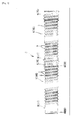
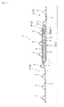
- FIG. 1 is an illustrative view showing a general configuration of a connection structure of metal-resin composite pipes relative to the present invention
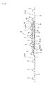
- FIG. 4 is an illustrative view showing a general configuration of a metal-resin composite pipe used in the connection structure.
- FIGS. 1 to 5 show a first embodiment of the present invention
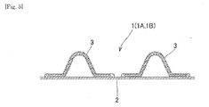
- FIGS. 6 and 7 show a second embodiment of the present invention.
- metal-resin composite pipes are marked with 1 (1A and 1B)
- a connection structure thereof is marked with S
- a main body is marked with 2
- a reinforcing convex part is marked with 3
- a diameter-expanded part is marked with 4
- a diameter-reduced part is marked with 5.
- the two metal-resin composite pipes 1A and 1B include each the main body 2 made of synthetic resin with an almost flat inner surface and the reinforcing convex part 3 formed of a metal member which is provided spirally around a periphery of the main body, and the pipes are connected with each other at ends thereof.
- the metal-resin composite pipes 1A and 1B connected with each other are metal-resin composite pipes 1 of the same structure with the diameter-expanded part 4 at one end and the diameter-reduced part 5 at the other end.
- connection structure of the present invention is not limited to this, and as far as pipes have the diameter-expanded part and the diameter-reduced part at least at the opposing ends thereof, one or both of the pipes may not have the diameter-reduced part or the diameter-expanded part at the other end(s).
- the metal-resin composite pipes 1 (1A and 1B) relative to the first embodiment include, as shown in FIGS. 1 , 4 and 5 , the main body 2 made of synthetic resin with an almost flat inner surface and the reinforcing convex part 3 formed of a metal member which is provided spirally around a periphery of the main body.
- the diameter-expanded part 4 is formed by pressurizing and deforming outward the reinforcing convex part 3 including the one end 10 together with the main body 2 positioned inside the reinforcing convex part.
- the diameter-reduced part 5 is formed by pressurizing and deforming inward at least the reinforcing convex part 3 including the other end 11.
- Synthetic resin forming the main body 2 is not particularly limited in kind and may be a polyolefin-based resin, a polyvinyl chloride-based resin, or another general resin. Preferably used is a polyethylene resin.
- the main body 2 and the reinforcing convex part 3 can be efficiently produced by, as is conventionally done, winding a partial molding of the main body 2 spirally around a rotating axis through melt extrusion and depositing it sequentially while supplying the reinforcing convex part 3 spirally as well onto the partial molding to integrate the main body 2 and the reinforcing convex part 3.
- a strip-shaped coating steel sheet with an angle section is supplied spirally around and integrated with the main body 2.
- a steel sheet may be inserted into a resin molded in the same shape as that of the sheet. Alternatively, it is preferable to insert a bar of metal other than steel sheet.
- the diameter-expanded part 4 formed at the one end 10 can be easily provided by deforming outward the main body 2 and the reinforcing convex part 3 so as to be expanded in diameter. This allows the reinforcing convex part 3 to be kept in an outward expanding state, whereby the main body 2 of synthetic resin integrated with the reinforcing convex part 3 is also held with a diameter expanded.
- the diameter-expanded part 4 may be in a shape of a tube with an axially uniform diameter, and also preferably may be in a shape of a trumpet flaring out toward an opening end.
- the diameter-reduced part 5 formed at the other end 11 can be easily provided by pressurizing and deforming the other end 11 so as to be reduced in diameter. In this embodiment, only the reinforcing convex part 3 is crushed under pressure, and the main body 2 with a diameter reduced may also be further reduced in diameter.
- tubular members 7 and 8 are attached to the inner surface of the diameter-expanded part 4 and the outer surface of the diameter-reduced part 5, respectively, in a water-tight manner using any one various sealing materials including a natural rubber, various synthetic rubbers such as urethane rubber, butyl rubber, NBR and SBR, water-expanding materials, various thermoplastic elastomers, foaming materials such as polyurethane foam, silicones as caulking agents, various liquid gaskets, and unvulcanized rubbers. These tubular members 7 and 8 are not necessarily essential components.
- the tubular members 7 and 8 which can be dimensioned in advance with high accuracy, the pipes can be expected to be sealed with excellent sealing properties between the inner surface of the main body at the pressurized and deformed diameter-expanded part 4 and the reinforcing convex part of the diameter-reduced part 5, and also the connection can be easily carried out, as compared to the case without using these members.
- the diameter-reduced part 5 is tapered down toward an opening end, and also the tapered tubular member 8 is attached to the outer surface of the diameter-reduced part 5.
- the tubular member 7 attached to the inner surface of the diameter-expanded part 4 has a tapered shape which is substantially parallel to the tubular member 8 and is at the substantially same angle as that of the tubular member 8.
- the pipes are sealed with an O-ring 60 as a sealing member 6 placed between these tubular members 7 and 8.
- These tubular members 7 and 8 are preferably made of a metal such as an iron sheet or a synthetic resin.
- pipe connection can be completed with a single motion, i.e. in the metal-resin composite pipes 1 of the above described structure, only by inserting the diameter-reduced part 5 of the second metal-resin composite pipe 1B into the diameter-expanded part 4 of the first metal-resin composite pipe 1A.
- the O-ring 60 (sealing member 6) may be attached at the time of pipe connection, and alternatively, may be attached in advance to an exterior of the tubular member 8 on a front edge side as shown in FIG. 2 , which leads to improvement in working efficiency.
- the O-ring 60 (sealing member 6) may be attached in advance to the tubular member 7 of the diameter-expanded part 4 so as to be fitted inside as shown in FIG. 3 , for example.
- the O-ring 60 is preferably fixed to the tubular member 7 with adhesive or the like.
- the sealing member 6 such as the O-ring 60 is not particularly limited in shape, structure and attachment position, provided that it securely seals the pipes between the tubular member 7 of the diameter-expanded part 4 and the tubular member 8 of the diameter-reduced part 5. Any of sealing members with various shapes and structures can be attached in an appropriate position.
- FIG. 6 shows a connection structure S of metal-resin composite pipes relative to the second embodiment.
- a distal end of the diameter-expanded part 4 of a first metal-resin composite pipe 1A and a distal end of the tubular member 7 attached to the inner surface of the diameter-expanded part 4 are aligned, and a first end-binding ring 72 is attached to sandwich these distal ends.
- a distal end of the diameter-reduced part 5 of a second metal-resin composite pipe 1B and a distal end of the tubular member 8 attached to the outer surface of the diameter-reduced part 5 are aligned, and a second end-binding ring 82 is attached to sandwich these distal ends.
- a proximal end of the tubular member 8 attached to the outer surface of the diameter-reduced part 5 of the second metal-resin composite pipe 1B is located outside the distal end of the tubular member 7 on the inner surface of the diameter-expanded part 4 when the second metal-resin composite pipe 1B is joined to the first metal-resin composite pipe 1A. Therefore, a sealing ring 83 is further placed to seal between the proximal end of the tubular member 8 and the outer surface of the second metal-resin composite pipe 1B.
- the first end-biding ring 72, the second end-binding ring 82 and the sealing ring 83 are made of natural or synthetic rubber, soft synthetic resin, or elastomer, for example.
- the first end-binding ring 72 may be attached after the placement of the tubular member 7, and the second end biding ring 82 and the sealing ring 83 may be attached in this order after the placement of the tubular member 8 and O-ring 60.
- These rings prevent the infiltration of rainwater or the like from the outside and the leakage of fluid or the like from the inside, and also provide the improvement of the appearance.
- the tubular members 7 and 8 of this embodiment are formed of synthetic resin.
- the tubular member 7 is provided with a spiral rib 71 on the outer peripheral surface opposing the diameter-expanded part 4 of the tapered tubular main body 70.
- the tubular member 8 is also provided with a spiral rib 81 on the inner peripheral surface opposing the diameter-reduced part 5 of the tapered tubular main body 80. Accordingly, the side sealed by the O-ring 60 is kept flat, and the outer peripheral surface and the inner peripheral surface are formed with the ribs that have no influence on sealing performance.
- These ribs 71 and 81 both stiffen the tubular main bodies 70 and 80 from being bent, and also keep the tubular main bodies 7 and 8 from being detached because these ribs bite into the sealing material 9 charged between the diameter-expanded part 4 or the diameter-reduced part 5.
- the ribs 71 and 81 may be plural annular ribs that are formed with a predetermined space left between them, instead of spiral ribs.
- the ribs 71 and 81 may be formed by injection molding or spiral extrusion molding so as to be integral with the tubular main bodies 70 and 80
- the tubular member 7 may be formed by: molding the tubular main body 70; winding the separately molded rib 71 around the outer peripheral surface of the tubular main body 70; and joining the rib 71 to the tubular main body 70.
- the ribs 71 and 81 each may be substantially triangle or square in cross section instead of semicircle, and may be a rib as a multi-winding part that is formed by winding in piles at the edge of the tubular main body in spiral extrusion molding of the tubular main body.
- the ribs are not limited in form to spiral or annular one and may take any other forms.
- the prevent invention may have any stiffening means other than the ribs and also may have no stiffening means.
- the other structures are basically the same in the first embodiment, and thus given the same reference numerals as those of the first embodiment and will not be described here.
Landscapes
- Engineering & Computer Science (AREA)
- General Engineering & Computer Science (AREA)
- Mechanical Engineering (AREA)
- Rigid Pipes And Flexible Pipes (AREA)
- Lining Or Joining Of Plastics Or The Like (AREA)
- Mutual Connection Of Rods And Tubes (AREA)
- Flanged Joints, Insulating Joints, And Other Joints (AREA)
Applications Claiming Priority (2)
| Application Number | Priority Date | Filing Date | Title |
|---|---|---|---|
| JP2007190257 | 2007-07-21 | ||
| JP2007288074A JP2009047302A (ja) | 2007-07-21 | 2007-11-06 | 金属樹脂複合管の接続構造、及び該接続構造に用いる金属樹脂複合管 |
Publications (2)
| Publication Number | Publication Date |
|---|---|
| EP2019247A2 true EP2019247A2 (de) | 2009-01-28 |
| EP2019247A3 EP2019247A3 (de) | 2009-09-02 |
Family
ID=39929741
Family Applications (1)
| Application Number | Title | Priority Date | Filing Date |
|---|---|---|---|
| EP08160207A Withdrawn EP2019247A3 (de) | 2007-07-21 | 2008-07-11 | Verbindungsstruktur für Metall-Harz-Verbindungsröhren und Metall-Harz-Verbindungsröhre zur Verwendung in der Verbindungsstruktur |
Country Status (3)
| Country | Link |
|---|---|
| US (1) | US20090021005A1 (de) |
| EP (1) | EP2019247A3 (de) |
| KR (1) | KR20090010011A (de) |
Families Citing this family (2)
| Publication number | Priority date | Publication date | Assignee | Title |
|---|---|---|---|---|
| CN101951070A (zh) * | 2010-08-13 | 2011-01-19 | 上海中科深江电动车辆有限公司 | 电动汽车永磁电机用磁钢冷却结构及其冷却方法 |
| KR20140020324A (ko) * | 2011-05-10 | 2014-02-18 | 가나플렉스 코포레이션 가부시키가이샤 | 조인트를 갖는 나선파형 합성 수지관 및 나선파형 합성 수지관의 접속 구조 |
Citations (1)
| Publication number | Priority date | Publication date | Assignee | Title |
|---|---|---|---|---|
| JP2002139178A (ja) | 2000-11-06 | 2002-05-17 | Kana Flex Corporation Kk | 大型管 |
Family Cites Families (28)
| Publication number | Priority date | Publication date | Assignee | Title |
|---|---|---|---|---|
| US801774A (en) * | 1904-11-05 | 1905-10-10 | Thomas Easton Devonshire | Conduit for electric cables or conductors. |
| US1258798A (en) * | 1917-04-12 | 1918-03-12 | James R Mcwane | Pipe-joint and filler therefor. |
| US1979470A (en) * | 1930-05-10 | 1934-11-06 | Gladding Mcbean & Company | Method of joining bell and spigot pipe sections |
| US2434107A (en) * | 1944-03-29 | 1948-01-06 | Rolfe A Folsom | Pipe joint |
| US2477533A (en) * | 1946-10-19 | 1949-07-26 | William A Whiting | Pipe joint |
| US2824575A (en) * | 1954-07-12 | 1958-02-25 | Milprint Inc | Air conditioner attachment |
| US3516693A (en) * | 1968-04-08 | 1970-06-23 | Hepworth Iron Co Ltd | Pipe couplings |
| US3482859A (en) * | 1968-11-04 | 1969-12-09 | John A Bowlin | Pipe joint |
| US3873134A (en) * | 1973-01-04 | 1975-03-25 | Michael Sammaritano | Apparatus for joining preformed conduits |
| US4079968A (en) * | 1976-01-02 | 1978-03-21 | Exxon Research & Engineering Co. | Nonambient temperature pipeline/joint assembly |
| US4394025A (en) * | 1981-11-09 | 1983-07-19 | Anderson Seal Company, Inc. | Pipe compression seal for bell and spigot joint |
| US4647085A (en) * | 1985-12-06 | 1987-03-03 | Anderson Edwin A | Sealing arrangement for pin and box threaded connection of tubular members |
| US5388870A (en) * | 1987-06-23 | 1995-02-14 | Proprietary Technology, Inc. | Apparatus for and method of attaching hoses and tubes to a fitting |
| US5209267A (en) * | 1988-05-31 | 1993-05-11 | Dana Corporation | Convoluted hose end assembly |
| JP3118579B2 (ja) * | 1992-12-09 | 2000-12-18 | 金尾 茂樹 | 耐圧合成樹脂管 |
| US5716078A (en) * | 1996-08-07 | 1998-02-10 | Powers; Ronald L. | Thermoplastic pipe joint |
| US5765880A (en) * | 1996-10-07 | 1998-06-16 | Advanced Drainage Systems, Inc. | Pipe coupler |
| US6082741A (en) * | 1996-11-28 | 2000-07-04 | Ipex Inc. | Resilient pipe gasket |
| JP3295734B2 (ja) * | 1998-09-25 | 2002-06-24 | 東拓工業株式会社 | 継手付き合成樹脂管 |
| US7469905B2 (en) * | 2000-11-30 | 2008-12-30 | Springseal Inc. | Permanently lubricated film gasket and method of manufacture |
| DK1235022T3 (da) * | 2001-02-09 | 2005-01-10 | Ralph-Peter Dr-Ing Hegler | Rör-byggesæt |
| US20030090112A1 (en) * | 2001-11-14 | 2003-05-15 | Brad Baughman | Pipe joint assembly |
| DE10328626A1 (de) * | 2003-06-26 | 2005-01-13 | Hegler, Ralph-Peter, Dr.-Ing. | Rohr-Bausatz |
| US20050161947A1 (en) * | 2003-10-28 | 2005-07-28 | Skinner James W. | Sealing system for pipelines |
| JP2005180609A (ja) * | 2003-12-19 | 2005-07-07 | Totaku Industries Inc | 耐圧複合管 |
| US7156128B1 (en) * | 2005-06-21 | 2007-01-02 | Kanaflex Corporation | Synthetic resin pipe |
| US7434850B2 (en) * | 2005-09-30 | 2008-10-14 | Prinsco, Inc. | Fluid-tight coupling system for corrugated pipe |
| US8820800B2 (en) * | 2007-11-16 | 2014-09-02 | Advanced Drainage Systems, Inc. | Multi-wall corrugated pipe couplings and methods |
-
2008
- 2008-07-08 KR KR1020080065951A patent/KR20090010011A/ko not_active Withdrawn
- 2008-07-11 EP EP08160207A patent/EP2019247A3/de not_active Withdrawn
- 2008-07-18 US US12/175,947 patent/US20090021005A1/en not_active Abandoned
Patent Citations (1)
| Publication number | Priority date | Publication date | Assignee | Title |
|---|---|---|---|---|
| JP2002139178A (ja) | 2000-11-06 | 2002-05-17 | Kana Flex Corporation Kk | 大型管 |
Also Published As
| Publication number | Publication date |
|---|---|
| EP2019247A3 (de) | 2009-09-02 |
| KR20090010011A (ko) | 2009-01-28 |
| US20090021005A1 (en) | 2009-01-22 |
Similar Documents
| Publication | Publication Date | Title |
|---|---|---|
| EP2098770A2 (de) | Anschlussvorrichtung für eine Wellschlauchleitung und Leitungssystem | |
| US20030136455A1 (en) | Block unit for repairing flow passage facilities and method of repairing flow passage facilities | |
| US4176865A (en) | Coupling for pipe | |
| US20040104576A1 (en) | Pipe clamp inner seal | |
| US8801049B2 (en) | Pipe coupling system and method | |
| US20090261576A1 (en) | Apparatus and method for supporting a pipe coupling | |
| US20050106347A1 (en) | Interlocked strip structure | |
| JP2009047302A (ja) | 金属樹脂複合管の接続構造、及び該接続構造に用いる金属樹脂複合管 | |
| JP2004514861A (ja) | 接続フランジを備える可撓性ホース、およびこのホースを製造する方法 | |
| CN114576434A (zh) | 一种埋地管道穿墙防水装置及安装方法 | |
| EP2019247A2 (de) | Verbindungsstruktur für Metall-Harz-Verbindungsröhren und Metall-Harz-Verbindungsröhre zur Verwendung in der Verbindungsstruktur | |
| US2698193A (en) | Pipe section | |
| JP4132740B2 (ja) | 管路の内張り構造 | |
| JP5014022B2 (ja) | 支管継手 | |
| JP3903373B2 (ja) | マンホール用止水可とう継手、マンホール構造及びマンホール構造の施工方法 | |
| JP5052276B2 (ja) | 閉塞具およびその取付方法 | |
| JP4014069B2 (ja) | 管路の補修方法および管路補修材 | |
| EP1384937A1 (de) | Blockeinheit für die Sanierung von Strömungskanäle und Verfahren zur Sanierung von Strömungskanäle | |
| KR200389344Y1 (ko) | 파형강관 연결장치 | |
| JP3556895B2 (ja) | 埋設管の性能向上が可能な更生工法 | |
| JP4305803B2 (ja) | 管路用内張り材端部の裏込め用構造 | |
| KR102454257B1 (ko) | 하수관 연결구조체 | |
| JP2006316539A (ja) | 既設管の補修構造 | |
| JPH08312835A (ja) | 既設管の更生方法 | |
| JP4319462B2 (ja) | リブ管用可撓継手 |
Legal Events
| Date | Code | Title | Description |
|---|---|---|---|
| PUAI | Public reference made under article 153(3) epc to a published international application that has entered the european phase |
Free format text: ORIGINAL CODE: 0009012 |
|
| AK | Designated contracting states |
Kind code of ref document: A2 Designated state(s): AT BE BG CH CY CZ DE DK EE ES FI FR GB GR HR HU IE IS IT LI LT LU LV MC MT NL NO PL PT RO SE SI SK TR |
|
| AX | Request for extension of the european patent |
Extension state: AL BA MK RS |
|
| PUAL | Search report despatched |
Free format text: ORIGINAL CODE: 0009013 |
|
| AK | Designated contracting states |
Kind code of ref document: A3 Designated state(s): AT BE BG CH CY CZ DE DK EE ES FI FR GB GR HR HU IE IS IT LI LT LU LV MC MT NL NO PL PT RO SE SI SK TR |
|
| AX | Request for extension of the european patent |
Extension state: AL BA MK RS |
|
| RIC1 | Information provided on ipc code assigned before grant |
Ipc: F16L 25/00 20060101ALI20090724BHEP Ipc: F16L 37/02 20060101AFI20081112BHEP |
|
| AKX | Designation fees paid |
Designated state(s): AT BE BG CH CY CZ DE DK EE ES FI FR GB GR HR HU IE IS IT LI LT LU LV MC MT NL NO PL PT RO SE SI SK TR |
|
| STAA | Information on the status of an ep patent application or granted ep patent |
Free format text: STATUS: THE APPLICATION IS DEEMED TO BE WITHDRAWN |
|
| 18D | Application deemed to be withdrawn |
Effective date: 20100303 |