EP2019178B1 - Gelenkstabschloss - Google Patents
Gelenkstabschloss Download PDFInfo
- Publication number
- EP2019178B1 EP2019178B1 EP20080010992 EP08010992A EP2019178B1 EP 2019178 B1 EP2019178 B1 EP 2019178B1 EP 20080010992 EP20080010992 EP 20080010992 EP 08010992 A EP08010992 A EP 08010992A EP 2019178 B1 EP2019178 B1 EP 2019178B1
- Authority
- EP
- European Patent Office
- Prior art keywords
- latch
- lock
- lock body
- jointed bar
- accordance
- Prior art date
- Legal status (The legal status is an assumption and is not a legal conclusion. Google has not performed a legal analysis and makes no representation as to the accuracy of the status listed.)
- Active
Links
- 230000000903 blocking effect Effects 0.000 claims description 4
- 230000008719 thickening Effects 0.000 description 4
- 230000037431 insertion Effects 0.000 description 3
- 238000003780 insertion Methods 0.000 description 3
- 229910000760 Hardened steel Inorganic materials 0.000 description 2
- 230000015572 biosynthetic process Effects 0.000 description 1
- 230000002996 emotional effect Effects 0.000 description 1
- 210000003746 feather Anatomy 0.000 description 1
- 238000010409 ironing Methods 0.000 description 1
- 230000014759 maintenance of location Effects 0.000 description 1
- 230000000149 penetrating effect Effects 0.000 description 1
- 238000007789 sealing Methods 0.000 description 1
Images

Classifications
-
- E—FIXED CONSTRUCTIONS
- E05—LOCKS; KEYS; WINDOW OR DOOR FITTINGS; SAFES
- E05B—LOCKS; ACCESSORIES THEREFOR; HANDCUFFS
- E05B67/00—Padlocks; Details thereof
- E05B67/003—Chain, wire or cable locks
-
- E—FIXED CONSTRUCTIONS
- E05—LOCKS; KEYS; WINDOW OR DOOR FITTINGS; SAFES
- E05B—LOCKS; ACCESSORIES THEREFOR; HANDCUFFS
- E05B37/00—Permutation or combination locks; Puzzle locks
- E05B37/02—Permutation or combination locks; Puzzle locks with tumbler discs or rings arranged on a single axis, each disc being adjustable independently of the others
- E05B37/025—Permutation or combination locks; Puzzle locks with tumbler discs or rings arranged on a single axis, each disc being adjustable independently of the others in padlocks
-
- E—FIXED CONSTRUCTIONS
- E05—LOCKS; KEYS; WINDOW OR DOOR FITTINGS; SAFES
- E05B—LOCKS; ACCESSORIES THEREFOR; HANDCUFFS
- E05B17/00—Accessories in connection with locks
- E05B17/0054—Fraction or shear lines; Slip-clutches, resilient parts or the like for preventing damage when forced or slammed
- E05B17/0062—Fraction or shear lines; Slip-clutches, resilient parts or the like for preventing damage when forced or slammed with destructive disengagement
-
- E—FIXED CONSTRUCTIONS
- E05—LOCKS; KEYS; WINDOW OR DOOR FITTINGS; SAFES
- E05B—LOCKS; ACCESSORIES THEREFOR; HANDCUFFS
- E05B71/00—Locks specially adapted for bicycles, other than padlocks
-
- Y—GENERAL TAGGING OF NEW TECHNOLOGICAL DEVELOPMENTS; GENERAL TAGGING OF CROSS-SECTIONAL TECHNOLOGIES SPANNING OVER SEVERAL SECTIONS OF THE IPC; TECHNICAL SUBJECTS COVERED BY FORMER USPC CROSS-REFERENCE ART COLLECTIONS [XRACs] AND DIGESTS
- Y10—TECHNICAL SUBJECTS COVERED BY FORMER USPC
- Y10T—TECHNICAL SUBJECTS COVERED BY FORMER US CLASSIFICATION
- Y10T70/00—Locks
- Y10T70/40—Portable
- Y10T70/402—Fetters
- Y10T70/409—Shackles
-
- Y—GENERAL TAGGING OF NEW TECHNOLOGICAL DEVELOPMENTS; GENERAL TAGGING OF CROSS-SECTIONAL TECHNOLOGIES SPANNING OVER SEVERAL SECTIONS OF THE IPC; TECHNICAL SUBJECTS COVERED BY FORMER USPC CROSS-REFERENCE ART COLLECTIONS [XRACs] AND DIGESTS
- Y10—TECHNICAL SUBJECTS COVERED BY FORMER USPC
- Y10T—TECHNICAL SUBJECTS COVERED BY FORMER US CLASSIFICATION
- Y10T70/00—Locks
- Y10T70/40—Portable
- Y10T70/413—Padlocks
- Y10T70/417—Combination-controlled
- Y10T70/435—Flexible shackle
-
- Y—GENERAL TAGGING OF NEW TECHNOLOGICAL DEVELOPMENTS; GENERAL TAGGING OF CROSS-SECTIONAL TECHNOLOGIES SPANNING OVER SEVERAL SECTIONS OF THE IPC; TECHNICAL SUBJECTS COVERED BY FORMER USPC CROSS-REFERENCE ART COLLECTIONS [XRACs] AND DIGESTS
- Y10—TECHNICAL SUBJECTS COVERED BY FORMER USPC
- Y10T—TECHNICAL SUBJECTS COVERED BY FORMER US CLASSIFICATION
- Y10T70/00—Locks
- Y10T70/40—Portable
- Y10T70/413—Padlocks
- Y10T70/437—Key-controlled
- Y10T70/483—Flexible shackle
-
- Y—GENERAL TAGGING OF NEW TECHNOLOGICAL DEVELOPMENTS; GENERAL TAGGING OF CROSS-SECTIONAL TECHNOLOGIES SPANNING OVER SEVERAL SECTIONS OF THE IPC; TECHNICAL SUBJECTS COVERED BY FORMER USPC CROSS-REFERENCE ART COLLECTIONS [XRACs] AND DIGESTS
- Y10—TECHNICAL SUBJECTS COVERED BY FORMER USPC
- Y10T—TECHNICAL SUBJECTS COVERED BY FORMER US CLASSIFICATION
- Y10T70/00—Locks
- Y10T70/50—Special application
- Y10T70/5611—For control and machine elements
- Y10T70/5646—Rotary shaft
- Y10T70/565—Locked stationary
- Y10T70/5655—Housing-carried lock
- Y10T70/5664—Latching bolt
Definitions
- the present invention relates to a hinged bar lock comprising a lock body and a hinge bar having first and second ends, the first end permanently connected to the lock body, and the second end connectable to the lock body at a lock portion of the lock body.
- a bolt provided on the lock body can be selectively moved to a locking position in which the latch engages the second end of the hinge bar when it is connected to the lock body, or the latch can be moved to a release position in which the second end of the Articulated bar is released for removal from the lock body.
- Such a hinged bar lock is off DE 10 2005 040 066 A1 known and used, for example, to secure a bicycle to a bicycle stand, a lamp post or the like.
- a hinged bar lock is off DE 10 2005 040 066 A1 known and used, for example, to secure a bicycle to a bicycle stand, a lamp post or the like.
- one after the other or in a row articulated hinged joint rods of the hinge bar are unfolded, and a closing rod on which the second end of the hinge bar is formed is locked to the lock body, thereby forming a closed loop.
- This closed loop may, for example, engage around a frame portion of the bicycle and the bicycle stand, lamp post or the like, or the hinged bar handle encloses only a rim of the bicycle to prevent unauthorized persons from driving away.
- a lock cylinder is used, which is rotatably actuated by an associated key or other identification means to move the latch selectively in the locked position or in the release position.
- the invention has for its object to provide a hinged bar lock with a numerical locking mechanism that is easy to use, the lock body has a small size and has an improved security against breakage.
- the number locking mechanism is intended to block the latch in said locking position or to release it for movement into said release position.
- the numerical locking mechanism may be a known number-locking mechanism having a plurality of juxtaposed, rotatable number rings that release the bolt of the toggle lock when setting a release number combination corresponding to a predetermined rotational position of the number rings to each other block the bar with other number combinations or rotary positions.
- the number-closing mechanism and the actuator are disposed on different sides with respect to the lock portion of the lock body.
- the bolt is biased in the locking position.
- the latch - if it is released by the number-locking mechanism - can be moved into the release position by simply pressing on the coupled via the connecting portion with the latch actuator.
- the actuating device is thus in particular a feeler device.
- the locking and unlocking of the second end of the hinge rod bracket on the lock body is particularly easy and comfortable possible when the number locking mechanism is in a position in which the latch is released.
- the actuator can be pressed to lock the actuator, then inserted the second end of the hinge rod bracket in the locking portion of the lock body and finally the actuator are released again.
- the actuator can be pressed to unlock the actuator, then removed the second end of the hinge rod bracket from the lock area of the lock body and finally the actuator are released again.
- the lock body of the hinge pin lock can be made particularly compact due to the simple structure of the locking mechanism.
- said connecting portion which couples the actuator to the latch, is fixedly connected to the latch, in particular an integral part of the latch.
- the connecting portion with respect to the longitudinal axis of the bolt which corresponds to the axis of rotation of the numerical locking mechanism, laterally offset. Due to the eccentric arrangement of the connecting portion with respect to the longitudinal axis of the bolt, a breaking tool, such as a screwdriver, which is forcibly inserted into the housing channel for the connecting portion, does not easily penetrate into the locking channel and thus into the area of the numerical locking mechanism. Thus, the security against breakage of the toggle bar lock can be increased.
- the connecting portion is formed weaker, in particular, the connecting portion has a smaller cross-sectional area than the part of the bolt, which is arranged in the locking position of the bolt in the locking region of the lock body. In the case of a break-in attempt, the connecting portion thus acts as a predetermined breaking point. If the connecting portion is broken, the bolt can not be moved and remains in the locking area of the lock housing, so that the second end of the hinged bar is blocked against removal from the lock body. It is sufficient if the connecting portion is formed weaker at least at one point, as the located in the locking position in the locking portion of the bolt.
- the second end of the hinged bar handle has an outwardly open passage slot which extends in particular parallel to the removal direction of the hinged bar handle.
- This passport passes inwardly into a latch receiving opening, which is widened with respect to the passage slot.
- the latch receiving aperture is adapted to permit engagement of the latch in the second end of the hinge bar strap to lock the second end of the hinge bar strap to the latch portion of the latch body.
- the width of the passage slot is smaller than the extension of the bolt receiving opening in the corresponding direction to prevent in the locking position of the bolt a threading of the bolt through the slot.
- the width of the passage slot corresponds to the width of the connecting portion or is greater than the width thereof, so that the second end of the hinge rod can be inserted into or removed from the lock body, in spite of the connecting portion penetrating the locking portion.
- the pass-through slot is preferably formed at the axial end of the closing rod of the articulated rod bracket in order to allow axial insertion of the locking rod into the locking region of the lock body with respect to the longitudinal axis of the locking rod.
- the pass-through slot can also be formed laterally of the axial end of the locking bar at the second end of the hinge rod bracket, in order to enable lateral pivoting of the second end of the hinge rod bracket into the locking region of the lock body.
- the locking portion of the lock body comprises a support portion which engages in the bolt receiving opening of the second end of the hinge bar, wherein the width of the support portion corresponds at most to the width of the aforementioned pass slot.
- the latch is then stabilized with respect to a lateral application of force, for example when trying to forcibly pull the second end of the hinge bar out of the latch body, without the latch engaging a housing portion of the latch body beyond the latching area, that is, beyond the plane of movement of the latch bar got to.
- the stability of the articulated bar lock can be increased.
- the increased stability is achieved with a minimum axial stroke of the bolt, whereby an advantageous size of the lock body is made possible. Since the width of the support portion corresponds at most to the width of the passage slot, it can be ensured that the support section does not hinder the insertion of the second end of the hinge rod bracket into the locking region of the lock body.
- the support section of the lock body engages in a support section receptacle formed on the end of the latch facing the connection section, wherein the latch adjacent to the support section receptacle has a blocking region, which optionally abuts against the support section.
- the bolt has at the connecting portion axially facing the end of a thickening, which is arranged in the locking position of the bolt in the locking region of the lock body.
- a thickening By thickening a laterally offset arrangement of the connecting portion relative to the longitudinal axis of the bolt can be facilitated.
- the contact area with which the latch cooperates lockingly with the second end of the hinged bar handle can be increased.
- the formation of a support section receptacle in the bolt can be facilitated.
- the thickening is preferably formed as a disc section. The thickening may be arranged eccentrically to the longitudinal axis of the bolt.
- the number-closing mechanism has a number-combination adjusting mechanism disposed at the axial end of the number-closing mechanism opposite to the locking portion. As a result, the adjustment is easily accessible when a new release number combination is to be set.
- the philosophicalkombinationsverstellmechanismus may be a per se known gestationverstellmechanismus.
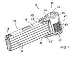
- the articulated bar lock shown has a lock body 11 and a hinged rod bracket 13 attached thereto.
- the articulated rod bracket 13 can, as in particular in FIGS Fig. 1 and 2 is shown folded into a compact unit and locked in this state also on the lock body 11.
- the Gelenkstabbügel 13 can also be unfolded (not shown) to a known per se To form a loop and thereby lock a bicycle or to another object, such as a bicycle stand to secure.
- the Gelenkstabbügel 13 has a plurality of hinge rods 15, one of which is designed as a closing rod 17.
- the joint rods 15, 17 are each formed flat and made of hardened steel.
- the articulated rods 15, 17 are hinged to one another in sequence in such a way by a respective rivet 19 that the articulation axes run parallel to one another and the articulated rod bracket 13 can be folded together in the manner of a folding rule.
- the longitudinal axes of the hinge rods 15, 17 extend in a plane parallel to each other.
- a first end 21 of the thus formed Gelenkstabbügels 13 is permanently articulated to the lock body 11.
- a second end 23 of the Gelenkstabbügels 13 is formed by the free end of the closing rod 17.
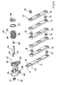
- the lock bar 17 has Fig. 3 an outwardly open passing slot 31 formed along the longitudinal axis of the lock bar 17.
- the passage slot 31 merges at its inner end into a circular latch receiving opening 41 whose diameter is greater than the width of the passage slot 31.
- the lock body 11 has an elongate housing 25, for example made of hardened steel, with a longitudinal axis which runs parallel to the joint axes of the joint rods 15, 17.
- a laterally projecting mounting portion 29 is integrally formed on the housing 25, to which the first end 21 of the Gelenkstabbügels 13 is articulated. Further, the housing 25 has at the first end 27 frontally a mounting opening 35, which opens into a cavity of the housing 25. Through the mounting hole 35, a lock mechanism is inserted into the housing 25, which includes an elongate latch 53 and a number-lock mechanism 47. The number-closing mechanism 47 has at its the mounting opening 35 end facing a philosophicalkombinationsverstellmechanismus. The mounting opening 35 is closed by a shutter disc 45 held by means of a securing ring 37.
- the housing 25 has a side receptacle 39.
- the side receptacle 39 is formed on a hinge bar 13 facing side surface of the housing 25 and serves to receive the second end 23 of the Gelenkstabbügels 13 and the free end of the Locking bar 17.
- the side receptacle 39 enters a locking area 59 (FIG. Fig. 2 ) of the lock body 11, in which the second end 23 of the Gelenkstabbügels 13 is when the locking bar 17 is completely inserted through the side receptacle 39 in the lock body 11.
- the extent of the locking portion 59 along said longitudinal axis of the housing 25 is determined by the clear height of the side receptacle 39, which in turn corresponds to the height of the free end 23 of the locking bar 17.
- a flat strap support 43 is integrally formed on the housing 25, which projects laterally from the housing 25 in alignment with the attachment section 29 at the first end 27 of the housing 25.
- the distance between the attachment portion 29 and the temple support 43 along the longitudinal axis of the housing 25 corresponds to the thickness or height of the folded hinge bar 13.
- the arranged in the cavity of the housing 25 numerical locking mechanism 47 comprises a plurality of juxtaposed, rotatable number rings 49 which form a latch channel, in which the latch 53 is inserted.
- the number rings 49 are adapted to allow each other at an adjustable predetermined rotational position an axial movement of the bolt 53 along its longitudinal axis, whereas in all other rotational positions of the number rings 49 to each other axial movement of the bolt 53 is blocked.
- the latch 53 has several along its longitudinal extent alternately arranged lateral elevations and depressions.
- the predetermined rotational position which may also be referred to as a latch release position, corresponds to a predetermined release-number combination which can be set in a known manner by the abovementioned number combination adjustment mechanism.
- the latch 53 protrudes from the latch channel formed by the number-closing mechanism 47 toward the second end 33 of the housing 25.
- a disc portion 57 At the second end 33 of the housing 25 facing the end of the bolt 53 is formed as a disc portion 57 ( Fig. 3 . 4 ), wherein the disc portion 57 is dimensioned larger in a direction radial to the longitudinal axis of the bolt 53, as the remaining portion of the bolt 53.
- the disc portion 57 is thereby arranged eccentrically to the longitudinal axis of the bolt 53.
- an elongated connecting portion 55 is integrally formed, on which a button 51 is attached.
- the connecting portion is laterally with respect to the longitudinal axis of the bolt 53 offset and arranged on an outer periphery of the disc portion 57.
- the key 51 is disposed opposite to the number-lock mechanism 47, that is, the key 51 is disposed on a different side of the lock portion 59 than the number-lock mechanism.
- a pushbutton section can be formed integrally in extension of the connecting section 55.
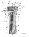
- Fig. 2 the bolt 53 is shown in the locking position, ie the bolt 53 engages in the second end 23 of the Gelenkstabbügels 13, wherein the latch 53 is biased by means of an inside of the shutter disc 45 supporting spring 65 in the direction of the locking position. More specifically, the disk portion 57 of the bolt 53 engages with the bolt receiving opening 41 of the lock bar 17, preventing retraction of the lock bar 17 from the lock body 11 due to the smaller width of the passport slot 31 with respect to the diameter of the disk portion 57.
- the connecting portion 55 extends in the locking position of the bolt 53 through the formed in the second end 23 of the Gelenkstabbügels 13 Passierschlitz 31 therethrough.
- the latch 53 has at its end facing the second end 33 of the housing 25, ie at the disc section 57, a support section receptacle 63 arranged adjacent to a blocking region 67 of the disc section 57 ( Fig. 4 ) into which a support section 61 (FIG. Fig. 2 ) of the lock body 11, wherein the support portion 61 is formed on an inner side of the second end 33 of the housing 25.
- the width of the support portion 61 corresponds in about the width of the passage slot 31 of the second end 23 of the hinge bar 13, so as not to hinder the insertion of the second end 23 of the hinge bar 13 in the lock body 11.
- the latch 53 In order to enable a release of the locking rod 17 of the lock body 11, the latch 53 by pressing the button 51, which is retractable in an outer recess of the housing 25, via the connecting portion 55 and against the bias of the spring 65 in a release position (not shown ) emotional. However, this presupposes that the number-closing mechanism 47 does not block the movement of the bolt 53.
- the disc portion 57 of the latch 53 By moving the latch 53 to the release position, the disc portion 57 of the latch 53 is temporarily disengaged from the latch receiving hole 41 of the lock rod 17, so that the lock rod 17 can be pulled out of the lock portion 59 and the side socket 39 of the lock body 11.
- the connecting portion 55 is located in the locking portion 59. However, the connecting portion 55, the removal of the locking rod 17 is not in the way, since the width of the connecting portion 55 corresponds approximately to the width of formed in the locking bar 17 Passierschlitzes 31st
Landscapes
- Lock And Its Accessories (AREA)
- Clamps And Clips (AREA)
- Refuge Islands, Traffic Blockers, Or Guard Fence (AREA)
Description
- Die vorliegende Erfindung betrifft ein Gelenkstabschloss mit einem Schlosskörper und einem Gelenkstabbügel, der ein erstes und ein zweites Ende besitzt, welches erste Ende dauerhaft mit dem Schlosskörper verbunden ist, und welches zweite Ende an einem Verriegelungsbereich des Schlosskörpers mit dem Schlosskörper verbindbar ist. Ein an dem Schlosskörper vorgesehener Riegel kann wahlweise in eine Verriegelungsstellung bewegt werden, in der der Riegel in das zweite Ende des Gelenkstabbügels eingreift, wenn dieses mit dem Schlosskörper verbunden ist, oder der Riegel kann in eine Freigabestellung bewegt werden, in der das zweite Ende des Gelenkstabbügels für eine Entnahme aus dem Schlosskörper freigegeben ist.
- Ein solches Gelenkstabschloss ist aus
DE 10 2005 040 066 A1 bekannt und dient beispielsweise zum Sichern eines Zweirads an einem Fahrradständer, einem Laternenpfosten oder dergleichen. Hierfür werden hintereinander bzw. in einer Reihe aneinander angelenkte Gelenkstäbe des Gelenkstabbügels auseinandergefaltet, und ein Schließstab, an dem das zweite Ende des Gelenkstabbügels ausbildet ist, wird an dem Schlosskörper verriegelt, um hierdurch eine geschlossene Schleife zu bilden. Diese geschlossene Schleife kann beispielsweise einen Rahmenabschnitt des Zweirads und den Fahrradständer, Laternenpfosten oder dergleichen umgreifen, oder der Gelenkstabbügel umschließt lediglich eine Felge des Zweirads, um unbefugte Personen am Wegfahren zu hindern. - Bei dem bekannten Gelenkstabschloss wird ein Schließzylinder verwendet, der durch einen zugeordneten Schlüssel oder ein sonstiges Identmittel drehbetätigbar ist, um den Riegel wahlweise in die Verriegelungsstellung oder in die Freigabestellung zu bewegen.
- Nachteilig hierbei ist jedoch, dass zwangsläufig ein Schlüssel mitgeführt werden muss, welcher darüber hinaus der Gefahr unterliegt, verloren zu werden. Viele Zweiradbesitzer bevorzugen zum Sichern ihrer Zweiräder daher Schlösser mit einem Zahlenschließmechanismus. Bei einer üblichen Anordnung eines Zahlenschließmechanismus beispielsweise an einem Kabelschloss ist eine Stirnseite des Zahlenschließmechanismus bei geöffnetem Schloss frei zugänglich, um einen Schlosskloben axial einführen zu können. Eine derartige Anordnung ist bei einem Gelenkstabschloss jedoch nicht ohne weiteres realisierbar.
- Dokument
EP 1536 091 A1 offenbart ein als Gelenktstabschloss ausgebildetes Bügelschloss mit den Merkmalen des Oberbegriffs des Anspruchs 1. - Dokument
US 5406811 zeigt ein Gelenkstabschloss mit einem Zahlenschließmechanismus. - Dokument
WO 2006/016280 A2 beschreibt ein Vorhangschloss, bei dem zwischen einer Betätigungsstange und einer hieran befestigten Taste eine Sollbruchfunktion vorgesehen ist. - Der Erfindung liegt die Aufgabe zugrunde, ein Gelenkstabschloss mit einem Zahlenschließmechanismus anzugeben, das einfach zu bedienen ist, dessen Schlosskörper eine geringe Baugröße besitzt und das eine verbesserte Aufbruchsicherheit besitzt.
- Diese Aufgabe wird durch ein Gelenkstabschloss mit den Merkmalen des Anspruchs 1 gelöst.
- Der Zahlenschließmechanismus ist dafür vorgesehen, den Riegel in der genannten Verriegelungsstellung zu blockieren oder für eine Bewegung in die genannte Freigabestellung freizugeben. Bei dem Zahlenschließmechanismus kann es sich um einen an sich bekannten Zahlenschließmechanismus handeln, der mehrere nebeneinander angeordnete, drehbare Zahlenringe aufweist, die bei Einstellung einer Freigabe-Zahlenkombination, welche einer vorgegebenen Drehstellung der Zahlenringe zueinander entspricht, den Riegel des Gelenkstabschlosses freigeben, und die bei allen anderen Zahlenkombinationen bzw. Drehstellungen den Riegel blockieren.
- Der Zahlenschließmechanismus und die Betätigungseinrichtung sind auf verschiedenen Seiten bezüglich des Verriegelungsbereichs des Schlosskörpers angeordnet. Der Riegel ist in die Verriegelungsstellung vorgespannt. Somit kann der Riegel - sofern er durch den Zahlenschließmechanismus freigegeben ist - durch einfaches Drücken auf die über den Verbindungsabschnitt mit dem Riegel gekoppelte Betätigungseinrichtung in die Freigabestellung bewegt werden. Bei der Betätigungseinrichtung handelt es sich folglich insbesondere um eine Tastereinrichtung.
- Hierdurch kann erreicht werden, dass das Verriegeln und Entriegeln des zweiten Endes des Gelenkstabbügels am Schlosskörper besonders einfach und komfortabel möglich ist, wenn der Zahlenschließmechanismus sich in einer Stellung befindet, in der der Riegel freigegeben ist. Beispielsweise kann zum Verriegeln die Betätigungseinrichtung gedrückt, dann das zweite Ende des Gelenkstabbügels in den Verriegelungsbereich des Schlosskörpers eingeführt und schließlich die Betätigungseinrichtung wieder losgelassen werden. Zum Entriegeln kann wiederum zunächst die Betätigungseinrichtung gedrückt, dann das zweite Ende des Gelenkstabbügels aus dem Verriegelungsbereich des Schlosskörpers entfernt und schließlich die Betätigungseinrichtung wieder losgelassen werden.
- Durch das Vorspannen des Riegels in die Verriegelungsstellung ist ein ungesichertes Halten des zweiten Endes des Gelenkstabbügels an dem Verriegelungsbereich des Schlosskörpers auch dann möglich, wenn an dem Zahlenschließmechanismus die vorgenannte Freigabe-Zahlenkombination eingestellt ist, d.h. wenn der Riegel nicht in der Verriegelungsstellung blockiert ist. Dies gewährleistet einerseits, dass beim Verriegeln des Gelenkstabbügels am Schlosskörper nicht auch gleichzeitig der Zahlenschließmechanismus verstellt werden muss. Andererseits wird beim Entriegeln das zweite Ende des Gelenkstabbügels nach Einstellen der Freigabe-Zahlenkombination nicht unmittelbar und unkontrolliert aus dem Verriegelungsbereich des Schlosskörpers freigegeben.
- Ferner kann der Schlosskörper des Gelenkstabschlosses aufgrund des einfachen Aufbaus des Verriegelungsmechanismus besonders kompakt ausgebildet werden.
- Gemäß einer bevorzugten Ausführungsform ist der genannte Verbindungsabschnitt, der die Betätigungseinrichtung mit dem Riegel koppelt, mit dem Riegel fest verbunden, insbesondere ein integraler Teil des Riegels.
- Nach einer weiteren Ausbildung der Erfindung ist der Verbindungsabschnitt bezüglich der Längsachse des Riegels, die der Drehachse des Zahlenschließmechanismus entspricht, seitlich versetzt. Durch die exzentrische Anordnung des Verbindungsabschnitts bezüglich der Längsachse des Riegels kann ein Aufbruchwerkzeug, beispielsweise ein Schraubendreher, welches gewaltsam in den Gehäusekanal für den Verbindungsabschnitt eingeführt wird, nicht ohne Weiteres in den Riegelkanal und somit in den Bereich des Zahlenschließmechanismus vordringen. Somit kann die Aufbruchsicherheit des Gelenkstabschlosses erhöht werden.
- Der Verbindungsabschnitt ist schwächer ausgebildet, insbesondere weist der Verbindungsabschnitt eine geringere Querschnittsfläche auf, als der Teil des Riegels, welcher in der Verriegelungsstellung des Riegels im Verriegelungsbereich des Schlosskörpers angeordnet ist. Im Falle eines Aufbruchversuchs wirkt der Verbindungsabschnitt somit als Sollbruchstelle. Ist der Verbindungsabschnitt gebrochen, kann der Riegel nicht mehr bewegt werden und verbleibt im Verriegelungsbereich des Schlossgehäuses, so dass das zweite Ende des Gelenkstabbügels gegen eine Entnahme aus dem Schlosskörper blockiert ist. Hierbei ist es ausreichend, wenn der Verbindungsabschnitt zumindest an einer Stelle schwächer ausgebildet ist, als der in der Verriegelungsstellung im Verriegelungsbereich befindliche Teil des Riegels.
- Das zweite Ende des Gelenkstabbügels weist einen nach außen offenen Passierschlitz auf, der insbesondere parallel zu der Entnahmerichtung des Gelenkstabbügels verläuft. Dieser Passierschlitz geht nach innen in eine Riegelaufnahmeöffnung über, welche bezüglich des Passierschlitzes verbreitert ist. Die Riegelaufnahmeöffnung ist dafür vorgesehen, ein Eingreifen des Riegels in das zweite Ende des Gelenkstabbügels zu ermöglichen, um das zweite Ende des Gelenkstabbügels an dem Verriegelungsbereich des Schlosskörpers zu verriegeln. Die Breite des Passierschlitzes ist dabei kleiner als die Erstreckung der Riegelaufnahmeöffnung in der entsprechenden Richtung, um in der Verriegelungsstellung des Riegels ein Ausfädeln des Riegels durch den Passierschlitz zu verhindern. Die Breite des Passierschlitzes entspricht der Breite des Verbindungsabschnitts oder ist größer als dessen Breite, so dass das zweite Ende des Gelenkstabbügels trotz des den Verriegelungsbereich durchdringenden Verbindungsabschnitts in den Schlosskörper eingeführt oder aus diesem entnommen werden kann. Der Passierschlitz ist bevorzugt an dem axialen Ende des Schließstabs des Gelenkstabbügels ausgebildet, um ein bezüglich der Längsachse des Schließstabs axiales Einführen des Schließstabs in den Verriegelungsbereich des Schlosskörpers zu ermöglichen. Grundsätzlich kann der Passierschlitz aber auch seitlich des axialen Endes des Schließstabs an dem zweiten Ende des Gelenkstabbügels ausgebildet sein, um ein seitliches Einschwenken des zweiten Endes des Gelenkstabbügels in den Verriegelungsbereich des Schlosskörpers zu ermöglichen.
- Bevorzugt umfasst der Verriegelungsbereich des Schlosskörpers einen Stützabschnitt, welcher in die Riegelaufnahmeöffnung des zweiten Endes des Gelenkstabbügels eingreift, wobei die Breite des Stützabschnitts höchstens der Breite des vorgenannten Passierschlitzes entspricht. Dies ermöglicht dem in der Verriegelungsstellung befindlichen Riegel, sich an dem Stützabschnitt des Schlosskörpers abzustützen. Der Riegel ist dann bezüglich einer seitlichen Kraftbeaufschlagung, beispielsweise wenn versucht wird, das zweite Ende des Gelenkstabbügels gewaltsam aus dem Schlosskörper zu ziehen, stabilisiert, ohne dass der Riegel hierfür in einen Gehäusebereich des Schlosskörpers jenseits des Verriegelungsbereichs, d.h. jenseits der Bewegungsebene des Schließstabs, eingreifen muss. Hierdurch kann die Stabilität des Gelenkstabschlosses erhöht werden. Die erhöhte Stabilität wird dabei bei einem minimalen axialen Hub des Riegels erreicht, wodurch eine vorteilhafte Baugröße des Schlosskörpers ermöglicht wird. Da die Breite des Stützabschnitts höchstens der Breite des Passierschlitzes entspricht, kann sichergestellt werden, dass der Stützabschnitt das Einführen des zweiten Endes des Gelenkstabbügels in den Verriegelungsbereich des Schlosskörpers nicht behindert.
- Insbesondere kann vorgesehen sein, dass der Stützabschnitt des Schlosskörpers in eine an dem dem Verbindungsabschnitt axial zugewandten Ende des Riegels ausgebildete Stützabschnittaufnahme eingreift, wobei der Riegel benachbart zu der Stützabschnittaufnahme einen Blockierbereich aufweist, der gegebenenfalls an dem Stützabschnitt anschlägt. Hierdurch kann die Stabilität des Gelenkstabschlosses weiter erhöht werden
- Der Riegel weist an dem dem Verbindungsabschnitt axial zugewandten Ende eine Verdickung auf, welche in der Verriegelungsstellung des Riegels im Verriegelungsbereich des Schlosskörpers angeordnet ist. Durch die Verdickung kann eine seitlich versetzte Anordnung des Verbindungsabschnitts bezüglich der Längsachse des Riegels erleichtert werden. Darüber hinaus kann der Kontaktbereich, mit dem der Riegel mit dem zweiten Ende des Gelenkstabbügels verriegelnd zusammenwirkt, vergrößert werden. Ferner kann die Ausbildung einer Stützabschnittaufnahme in dem Riegel erleichtert werden. Die Verdickung ist bevorzugt als Scheibenabschnitt ausgebildet. Die Verdickung kann exzentrisch zu der Längsachse des Riegels angeordnet sein.
- Weiterhin ist es bevorzugt, wenn der Zahlenschließmechanismus einen Zahlenkombinationsverstellmechanismus aufweist, der an dem dem Verriegelungsbereich gegenüberliegenden axialen Ende des Zahlenschließmechanismus angeordnet ist. Hierdurch ist der Verstellmechanismus gut zugänglich, wenn eine neue Freigabe-Zahlenkombination eingestellt werden soll. Bei dem Zahlenkombinationsverstellmechanismus kann es sich um einen an sich bekannten Zahlenkombinationsverstellmechanismus handeln.
- Vorteilhaft ist es auch, wenn das zweite Ende des Gelenkstabbügels gehärtet ist. Hierdurch kann die Aufbruchsicherheit des Gelenkstabschlosses weiter erhöht werden.
- Weitere Ausführungsformen der durch den Hauptanspruch definierten Erfindung sind in den Unteransprüchen, der Beschreibung und der Zeichnung angegeben.
- Die Erfindung wird nachfolgend lediglich beispielhaft unter Bezugnahme auf die Zeichnung erläutert.
- Es zeigen, jeweils in schematischer Darstellung,
- Fig. 1
- eine perspektivische Ansicht eines Gelenkstabschlosses von schräg oben,
- Fig. 2
- eine Querschnittsansicht des Gelenkstabschlosses von
Fig. 1 , - Fig. 3
- eine Explosionsansicht des Gelenkstabschlosses von
Fig. 1 , und - Fig. 4
- vergrößerte Perspektivansichten des in den
Fig. 2 und3 sichtbaren Riegels. - Das gezeigte Gelenkstabschloss besitzt einen Schlosskörper 11 und einen daran befestigten Gelenkstabbügel 13. Der Gelenkstabbügel 13 kann, wie insbesondere in den
Fig. 1 und2 gezeigt ist, zu einer kompakten Einheit zusammengefaltet und in diesem Zustand auch an dem Schlosskörper 11 verriegelt werden. Der Gelenkstabbügel 13 kann jedoch auch auseinandergefaltet werden (nicht gezeigt), um auf an sich bekannte Weise eine Schleife zu bilden und hierdurch ein Zweirad abzusperren oder an einem anderen Gegenstand, beispielsweise einem Fahrradständer, zu sichern. - Im Einzelnen besitzt der Gelenkstabbügel 13 mehrere Gelenkstäbe 15, von denen einer als ein Schließstab 17 ausgebildet ist. Die Gelenkstäbe 15, 17 sind jeweils flach ausgebildet und bestehen aus gehärtetem Stahl. Die Gelenkstäbe 15, 17 sind durch einen jeweiligen Niet 19 dergestalt der Reihe nach aneinander angelenkt, dass die Gelenkachsen parallel zueinander verlaufen und der Gelenkstabbügel 13 nach Art eines Zollstocks zusammengefaltet werden kann. Im zusammengefalteten Zustand des Gelenkstabbügels 13 verlaufen die Längsachsen der Gelenkstäbe 15, 17 in einer Ebene parallel zueinander.
- Ein erstes Ende 21 des somit gebildeten Gelenkstabbügels 13 ist an dem Schlosskörper 11 dauerhaft angelenkt. Ein zweites Ende 23 des Gelenkstabbügels 13 ist durch das freie Ende des Schließstabs 17 gebildet. An seinem freien Ende besitzt der Schließstab 17 gemäß
Fig. 3 einen nach außen offenen Passierschlitz 31, der entlang der Längsachse des Schließstabs 17 ausgebildet ist. Der Passierschlitz 31 geht an seinem inneren Ende in eine kreisrunde Riegelaufnahmeöffnung 41 über, deren Durchmesser größer ist als die Breite des Passierschlitzes 31. - Der Schlosskörper 11 besitzt ein längliches Gehäuse 25, beispielsweise aus gehärtetem Stahl, mit einer Längsachse, die parallel zu den Gelenkachsen der Gelenkstäbe 15, 17 verläuft.
- An einem ersten Ende 27 des Gehäuses 25 ist an dem Gehäuse 25 ein seitlich abstehender Befestigungsabschnitt 29 angeformt, an dem das erste Ende 21 des Gelenkstabbügels 13 angelenkt ist. Ferner besitzt das Gehäuse 25 an dem ersten Ende 27 stirnseitig eine Montageöffnung 35, die in einen Hohlraum des Gehäuses 25 mündet. Über die Montageöffnung 35 ist ein Verriegelungsmechanismus in das Gehäuse 25 eingesetzt, der einen länglichen Riegel 53 und einen Zahlenschließmechanismus 47 umfasst. Der Zahlenschließmechanismus 47 besitzt an seinem der Montageöffnung 35 zugewandten Ende einen Zahlenkombinationsverstellmechanismus. Die Montageöffnung 35 ist durch eine mittels eines Sicherungsrings 37 gehaltene Verschlussscheibe 45 verschlossen.
- An einem dem ersten Ende 27 gegenüberliegenden zweiten Ende 33 besitzt das Gehäuse 25 eine Seitenaufnahme 39. Die Seitenaufnahme 39 ist an einer dem Gelenkstabbügel 13 zugewandten Seitenfläche des Gehäuses 25 ausgebildet und dient zur Aufnahme des zweiten Endes 23 des Gelenkstabbügels 13 bzw. des freien Endes des Schließstabs 17. Die Seitenaufnahme 39 geht in einen Verriegelungsbereich 59 (
Fig. 2 ) des Schlosskörpers 11 über, in dem sich das zweite Ende 23 des Gelenkstabbügels 13 befindet, wenn der Schließstab 17 vollständig durch die Seitenaufnahme 39 in den Schlosskörpers 11 eingeführt ist. Die Erstreckung des Verriegelungsbereichs 59 entlang der genannten Längsachse des Gehäuses 25 ist durch die lichte Höhe der Seitenaufnahme 39 vorgegeben, welche wiederum der Höhe des freien Endes 23 des Schließstabs 17 entspricht. - Ist der Schließstab 17 in die Seitenaufnahme 39 eingeführt, wird der Schließstab 17 von der Begrenzung der Seitenaufnahme 39 des Gehäuses 25 im Wesentlichen formschlüssig umschlossen. An dem zweiten Ende 33 des Gehäuses 25 ist an dem Gehäuse 25 eine flache Bügelauflage 43 angeformt, die fluchtend zu dem Befestigungsabschnitt 29 an dem ersten Ende 27 des Gehäuses 25 seitlich von dem Gehäuse 25 absteht. Der Abstand zwischen dem Befestigungsabschnitt 29 und der Bügelauflage 43 entlang der Längsachse des Gehäuses 25 entspricht der Dicke bzw. Höhe des zusammengefalteten Gelenkstabbügels 13.
- Der in den Hohlraum des Gehäuses 25 angeordnete Zahlenschließmechanismus 47 umfasst mehrere nebeneinander angeordnete, drehbare Zahlenringe 49, die einen Riegelkanal bilden, in welchem der Riegel 53 eingesetzt ist. Die Zahlenringe 49 sind dazu ausgelegt, bei einer verstellbar vorgegebenen Drehstellung zueinander eine axiale Bewegung des Riegels 53 entlang seiner Längsachse zu gestatten, wohingegen bei allen anderen Drehstellungen der Zahlenringe 49 zueinander eine axiale Bewegung des Riegels 53 blockiert wird. Hierfür besitzt der Riegel 53 mehrere entlang seiner Längserstreckung alternierend angeordnete seitliche Erhöhungen und Vertiefungen. Die vorgegebene Drehstellung, welche auch als Riegelfreigabestellung bezeichnet werden kann, entspricht einer vorgegebenen Freigabe-Zahlenkombination, welche durch den vorgenannten Zahlenkombinationsverstellmechanismus auf an sich in bekannter Weise einstellbar ist. Mittels des Zahlenschließmechanismus 47 kann eine axiale Bewegung des Riegels 53 bezüglich seiner Längsachse also wahlweise blockiert oder freigegeben werden.
- Der Riegel 53 steht aus dem Riegelkanal, der durch den Zahlenschließmechanismus 47 gebildet ist, in Richtung des zweiten Endes 33 des Gehäuses 25 hervor. An dem dem zweiten Ende 33 des Gehäuses 25 zugewandten Ende ist der Riegel 53 als Scheibenabschnitt 57 ausgebildet (
Fig. 3 ,4 ), wobei der Scheibenabschnitt 57 in einer Richtung radial zu der Längsachse des Riegels 53 größer dimensioniert ist, als der übrige Abschnitt des Riegels 53. Der Scheibenabschnitt 57 ist dabei exzentrisch zu der Längsachse des Riegels 53 angeordnet. - An dem Scheibenabschnitt 57 des Riegels 53 ist ein länglicher Verbindungsabschnitt 55 angeformt, an dem ein Taster 51 befestigt ist. Der Verbindungsabschnitt ist bezüglich der Längsachse des Riegels 53 seitlich versetzt und an einem Außenumfang des Scheibenabschnitts 57 angeordnet. Bezüglich des Verriegelungsbereichs 59 ist der Taster 51 gegenüberliegend zu dem Zahlenschließmechanismus 47 angeordnet, d.h. der Taster 51 ist auf einer anderen Seite des Verriegelungsbereichs 59 angeordnet als der Zahlenschließmechanismus. Anstelle eines separaten Tasters 51 kann in Verlängerung des Verbindungsabschnitts 55 ein Tasterabschnitt integral angeformt sein.
- In
Fig. 2 ist der Riegel 53 in der Verriegelungsstellung dargestellt, d.h. der Riegel 53 greift in das zweite Ende 23 des Gelenkstabbügels 13 ein, wobei der Riegel 53 mittels einer sich an einer Innenseite der Verschlussscheibe 45 abstützenden Feder 65 in Richtung der Verriegelungsstellung vorgespannt ist. Genauer greift der Scheibenabschnitt 57 des Riegels 53 in die Riegelaufnahmeöffnung 41 des Schließstabs 17 ein, wobei ein Zurückziehen des Schließstabs 17 aus dem Schlosskörper 11 aufgrund der geringeren Breite des Passierschlitzes 31 gegenüber dem Durchmesser des Scheibenabschnitts 57 verhindert wird. Der Verbindungsabschnitt 55 erstreckt sich in der Verriegelungsstellung des Riegels 53 durch den in dem zweiten Ende 23 des Gelenkstabbügels 13 ausgebildeten Passierschlitz 31 hindurch. - Darüber hinaus weist der Riegel 53 an seinem dem zweiten Ende 33 des Gehäuses 25 zugewandten Ende, d.h. an dem Scheibenabschnitt 57, eine benachbart zu einem Blockierbereich 67 des Scheibenabschnitts 57 angeordnete Stützabschnittaufnahme 63 auf (
Fig. 4 ), in die ein Stützabschnitt 61 (Fig. 2 ) des Schlosskörpers 11 eingreift, wobei der Stützabschnitt 61 an einer Innenseite des zweiten Endes 33 des Gehäuses 25 ausgebildet ist. Hierdurch kann eine wirksame Abstützung des Riegels 53 erreicht werden, falls versucht werden sollte, den Schließstab 17 gewaltsam aus dem Schlosskörper 11 zu ziehen. Die Breite des Stützabschnitts 61 entspricht in etwa der Breite des Passierschlitzes 31 des zweiten Endes 23 des Gelenkstabbügels 13, um das Einführen des zweiten Endes 23 des Gelenkstabbügels 13 in den Schlosskörper 11 nicht zu behindern. - Um ein Lösen des Schließstabs 17 von dem Schlosskörper 11 zu ermöglichen, wird der Riegel 53 durch Drücken des Tasters 51, welcher in einer Außenausnehmung des Gehäuses 25 versenkbar ist, über den Verbindungsabschnitt 55 und entgegen der Vorspannung der Feder 65 in eine Freigabestellung (nicht dargestellt) bewegt. Dies setzt jedoch voraus, dass der Zahlenschließmechanismus 47 die Bewegung des Riegels 53 nicht blockiert. Durch Bewegen des Riegels 53 in die Freigabestellung wird der Scheibenabschnitt 57 des Riegels 53 zeitweise außer Eingriff mit der Riegelaufnahmeöffnung 41 des Schließstabs 17 gesetzt, so dass der Schließstab 17 aus dem Verriegelungsbereich 59 und der Seitenaufnahme 39 des Schlosskörper 11 herausgezogen werden kann. Der Verbindungsabschnitt 55 befindet sich hierbei zwar im Verriegelungsbereich 59. Allerdings steht der Verbindungsabschnitt 55 der Entnahme des Schließstabs 17 nicht im Wege, da die Breite des Verbindungsabschnitts 55 in etwa der Breite des in dem Schließstab 17 ausgebildeten Passierschlitzes 31 entspricht.
- Das anhand der Figuren beschriebene Gelenkstabschloss mit dem Zahlenschließmechanismus ermöglicht aufgrund des in die Verriegelungsstellung vorgespannten Riegels und der bezüglich des Verriegelungsbereichs gegenüberliegenden Anordnung des Tasters und des Zahlenschließmechanismus eine besonders einfache Bedienung, wobei gleichzeitig eine geringe Baugröße des Schlosskörpers gewährleistet werden kann.
-
- 11
- Schlosskörper
- 13
- Gelenkstabbügel
- 15
- Gelenkstab
- 17
- Schließstab
- 19
- Niet
- 21
- erstes Ende des Gelenkstabbügels
- 23
- zweites Ende des Gelenkstabbügels
- 25
- Gehäuse
- 27
- erstes Ende des Gehäuses
- 29
- Befestigungsabschnitt
- 31
- Passierschlitz
- 33
- zweites Ende des Gehäuses
- 35
- Montageöffnung
- 37
- Sicherungsring
- 39
- Seitenaufnahme
- 41
- Riegelaufnahmeöffnung
- 43
- Bügelauflage
- 45
- Verschlussscheibe
- 47
- Zahlenschließmechanismus
- 49
- Zahlenring
- 51
- Taster
- 53
- Riegel
- 55
- Verbindungsabschnitt
- 57
- Scheibenabschnitt
- 59
- Verriegelungsbereich
- 61
- Stützabschnitt
- 63
- Stützabschnittaufnahme
- 65
- Feder
- 67
- Blockierbereich
Claims (10)
- Gelenkstabschloss mit einem Schlosskörper (11) und einem Gelenkstabbügel (13), der ein erstes Ende (21) und ein zweites Ende (23) besitzt, welches erste Ende (21) dauerhaft mit dem Schlosskörper (11) verbunden ist, und welches zweite Ende (23) an einem Verriegelungsbereich (59) des Schlosskörpers (11) mit dem Schlosskörper (11) verbindbar ist, wobei ein an dem Schlosskörper (11) vorgesehener Riegel (53) wahlweise in eine Verriegelungsstellung bewegbar ist, in der der Riegel (53) in das zweite Ende (23) des Gelenkstabbügels (13) eingreift, wenn dieses mit dem Schlosskörper (11) verbunden ist, oder in eine Freigabestellung bewegbar ist, in der das zweite Ende (23) des Gelenkstabbügels (13) für eine Entnahme aus dem Schlosskörper (11) freigegeben ist, wobei das Schloss eine über einen Verbindungsabschnitt (55) mit dem Riegel (53) gekoppelte Betätigungseinrichtung (51) aufweist, durch die der Riegel (53) aus der Verriegelungsstellung, in welche der Riegel (53) vorgespannt ist, in die Freigabestellung bewegbar ist, wobei der Schlosskörper (11) einen Zahlenschließmechanismus (47) beherbergt, um den Riegel (53) wahlweise zu blockieren oder freizugeben, wobei die Betätigungseinrichtung (51) bezüglich des Verriegelungsbereichs (59) des Schlosskörpers (11) gegenüberliegend zu dem Zahlenschließmechanismus (47) angeordnet ist, wobei das zweite Ende (23) des Gelenkstabbügels (13) eine Riegelaufnahme (41) aufweist, in die der Riegel (53) in der Verriegelungsstellung eingreift, und wobei in der Freigabestellung des Riegels (53) der Verbindungsabschnitt (55) im Verriegelungsbereich (59) des Schlosskörpers (11) angeordnet ist,
und wobei
das zweite Ende (23) des Gelenkstabbügels (13) einen nach außen offenen Passierschlitz (31) aufweist, dadurch gekennzeichnet, dass die Breite des zwischen dem Riegel (53) und der Betätigungseinrichtung (51) vorgesehenen Verbindungsabschnitts (55) höchstens der Breite des Passierschlitzes (31) entspricht, wobei der Riegel (53) an dem dem Verbindungsabschnitt (55) zugewandten Ende eine Verdickung (57) aufweist, welche in der Verriegelungsstellung des Riegels (53) im Verriegelungsbereich (59) des Schlosskörpers (11) angeordnet ist, und wobei der zwischen der Verdickung (57) und der Betätigungseinrichtung (51) vorgesehene Verbindungsabschnitt (55) schwächer ausgebildet ist als die Verdickung (57). - Gelenkstabschloss nach Anspruch 1,
dadurch gekennzeichnet ,
dass der Verbindungsabschnitt (55) mit dem Riegel (53) fest verbunden ist, insbesondere einstückig ausgebildet ist. - Gelenkstabschloss nach Anspruch 1 oder 2,
dadurch gekennzeichnet ,
dass der Verbindungsabschnitt (55) bezüglich der Längsachse des Riegels (53) seitlich versetzt ist. - Gelenkstabschloss nach einem der vorstehenden Ansprüche,
dadurch gekennzeichnet,
dass der Verbindungsabschnitt (55) eine geringere Querschnittsfläche aufweist als die in der Verriegelungsstellung des Riegels (53) im Verriegelungsbereich (59) des Schlosskörpers (11) angeordnete Verdickung (57). - Gelenkstabschloss nach einem der vorstehenden Ansprüche,
dadurch gekennzeichnet ,
dass die Betätigungseinrichtung (51) einen Taster aufweist, der mit dem Verbindungsabschnitt (55) fest verbunden ist, oder dass die Betätigungseinrichtung durch einen Tasterabschnitt gebildet ist, der über den Verbindungsabschnitt (55) mit dem Riegel (53) einstückig ausgebildet ist. - Gelenkstabschloss nach einem der vorstehenden Ansprüche,
dadurch gekennzeichnet ,
dass der Schlosskörper (11) im Verriegelungsbereich (59) einen Stützabschnitt (61) umfasst, welcher in die Riegelaufnahme (41) des Gelenkstabbügels (13) eingreift, wenn das zweite Ende (23) des Gelenkstabbügels (13) mit dem Schlosskörper (11) verbunden ist, wobei die Breite des Stützabschnitts (61) höchstens der Breite des Passierschlitzes (31) entspricht. - Gelenkstabschloss nach Anspruch 6,
dadurch gekennzeichnet ,
dass in der Verriegelungsstellung des Riegels (53) der Stützabschnitt (61) des Schlosskörpers (11) in eine Stützabschnittaufnahme (63) des Riegels (53) eingreift, wobei der Riegel (53) einen Blockierbereich (67) aufweist, der entgegen der Entnahmerichtung des Gelenkstabbügels (13) benachbart zu der Stützabschnittaufnahme (63) angeordnet ist. - Gelenkstabschloss nach einem der vorstehenden Ansprüche,
dadurch gekennzeichnet ,
dass die Verdickung (57) als Scheibenabschnitt ausgebildet ist. - Gelenkstabschloss nach einem der vorstehenden Ansprüche,
dadurch gekennzeichnet ,
dass der Zahlenschließmechanismus (47) einen Zahlenkombinationsverstellmechanismus aufweist, der an dem dem Verriegelungsbereich (59) gegenüberliegenden Ende des Zahlenschließmechanismus (47) angeordnet ist. - Gelenkstabschloss nach einem der vorstehenden Ansprüche,
dadurch gekennzeichnet ,
dass das zweite Ende (23) des Gelenkstabbügels (13) gehärtet ist.
Applications Claiming Priority (1)
| Application Number | Priority Date | Filing Date | Title |
|---|---|---|---|
| DE200710035116 DE102007035116A1 (de) | 2007-07-27 | 2007-07-27 | Gelenkstabschloss |
Publications (3)
| Publication Number | Publication Date |
|---|---|
| EP2019178A2 EP2019178A2 (de) | 2009-01-28 |
| EP2019178A3 EP2019178A3 (de) | 2011-05-04 |
| EP2019178B1 true EP2019178B1 (de) | 2013-08-14 |
Family
ID=40043994
Family Applications (1)
| Application Number | Title | Priority Date | Filing Date |
|---|---|---|---|
| EP20080010992 Active EP2019178B1 (de) | 2007-07-27 | 2008-06-17 | Gelenkstabschloss |
Country Status (4)
| Country | Link |
|---|---|
| US (1) | US7712339B2 (de) |
| EP (1) | EP2019178B1 (de) |
| CA (1) | CA2638047C (de) |
| DE (1) | DE102007035116A1 (de) |
Cited By (2)
| Publication number | Priority date | Publication date | Assignee | Title |
|---|---|---|---|---|
| EP3095932A1 (de) | 2015-05-21 | 2016-11-23 | ABUS August Bremicker Söhne KG | Zweirad-schloss |
| DE102020116154B3 (de) * | 2020-06-18 | 2021-05-27 | ABUS August Bremicker Söhne Kommanditgesellschaft | Halterung für ein tragbares Schloss |
Families Citing this family (27)
| Publication number | Priority date | Publication date | Assignee | Title |
|---|---|---|---|---|
| DE102009030036A1 (de) * | 2009-06-23 | 2010-12-30 | ABUS August Bremicker Söhne KG | Gelenkschloss |
| US8555682B2 (en) * | 2010-03-12 | 2013-10-15 | Christopher Trunek | Linkage lock |
| US8621898B2 (en) | 2010-06-22 | 2014-01-07 | Sinoxlock (Kunshan) Co., Ltd. | Foldable lock |
| JP3171356U (ja) | 2010-12-20 | 2011-10-27 | 競泰股▲分▼有限公司 | ロック装置 |
| GB2495482B (en) * | 2011-10-05 | 2016-02-03 | Patrick Elson | Cycle accessory |
| US8904831B2 (en) | 2012-08-28 | 2014-12-09 | Master Lock Company Llc | Locking arrangements |
| DE202013102264U1 (de) | 2013-05-24 | 2013-07-09 | Sinox Co., Ltd. | Kettenschloß |
| DE102013210475A1 (de) | 2013-06-05 | 2014-12-11 | ABUS August Bremicker Söhne KG | Gelenkschloss |
| US8881559B1 (en) * | 2014-04-28 | 2014-11-11 | Vulcan Sports Co., Ltd. | Foldable lock |
| TWM519165U (zh) * | 2015-08-18 | 2016-03-21 | 競泰股份有限公司 | 鍊條鎖 |
| TWM530338U (zh) | 2015-09-25 | 2016-10-11 | 競泰股份有限公司 | 鍊條鎖 |
| US9878752B2 (en) * | 2015-10-30 | 2018-01-30 | Altor Locks, Llc | Folding anti-theft device |
| DE202016000005U1 (de) | 2016-01-05 | 2016-02-01 | Sinox Co., Ltd. | Kettenschloss |
| DE202016000006U1 (de) | 2016-01-05 | 2016-02-01 | Sinox Co., Ltd. | Kettenschloss |
| WO2017182979A1 (en) * | 2016-04-20 | 2017-10-26 | Ino Vision Ltd. | Folding bicycle lock with joint protection |
| US10946914B2 (en) * | 2017-12-13 | 2021-03-16 | Adamant Conceptions Inc. | Chain assembly and a bicycle lock manufactured therefrom |
| ES2934588T3 (es) | 2018-04-03 | 2023-02-23 | Knox Ass Inc Dba Knox Company | Protector y absorbedor de fluidos para dispositivos de bloqueo |
| WO2020055891A1 (en) * | 2018-09-11 | 2020-03-19 | Lobster Lock, Llc | Locking device |
| TWM575470U (zh) | 2018-10-26 | 2019-03-11 | 競泰股份有限公司 | 鍊條鎖 |
| DE102019113377A1 (de) | 2019-05-20 | 2020-11-26 | ABUS August Bremicker Söhne Kommanditgesellschaft | Gelenkschloss |
| DE102019113387A1 (de) | 2019-05-20 | 2020-11-26 | ABUS August Bremicker Söhne Kommanditgesellschaft | Gelenkschloss |
| DE102019113378A1 (de) | 2019-05-20 | 2020-11-26 | ABUS August Bremicker Söhne Kommanditgesellschaft | Gelenkschloss |
| DE102019113388A1 (de) * | 2019-05-20 | 2020-11-26 | ABUS August Bremicker Söhne Kommanditgesellschaft | Gelenkschloss |
| USD974872S1 (en) * | 2020-06-09 | 2023-01-10 | ABUS August Bremicker Söhne KG | Lock |
| TWD215869S (zh) * | 2020-09-23 | 2021-12-11 | 競泰股份有限公司 | 折疊鎖 |
| TWM618643U (zh) | 2021-06-25 | 2021-10-21 | 林澤浩 | 固定裝置 |
| TWM627717U (zh) | 2021-12-28 | 2022-06-01 | 競泰股份有限公司 | 盤形鎖 |
Family Cites Families (21)
| Publication number | Priority date | Publication date | Assignee | Title |
|---|---|---|---|---|
| US1718723A (en) * | 1928-03-26 | 1929-06-25 | Williams Harry | Padlock |
| DE3410047C2 (de) * | 1983-03-23 | 1986-09-25 | S. Franzen Söhne (GmbH & Co), 5650 Solingen | Permutationsschloß mit Schlüsselgeheimnis-Neueinstellvorrichtung |
| JPH0742821B2 (ja) * | 1993-03-24 | 1995-05-10 | 株式会社クローバー | 車両用錠装置 |
| TW260732B (de) * | 1993-09-08 | 1995-10-21 | Winkhaus Fa August | |
| IT1285598B1 (it) * | 1996-03-07 | 1998-06-18 | I P Innovative Products Srl | Dispositivo antifurto pieghevole |
| US5791169A (en) * | 1997-08-27 | 1998-08-11 | Kuo; Lambert | U-shape lock |
| US5924313A (en) * | 1998-09-09 | 1999-07-20 | Kuo; Lambert | Combination lock with a device for changing the combination |
| US6101852A (en) * | 1999-03-05 | 2000-08-15 | Compx International Inc. | Padlock with removable shackle |
| US6386005B1 (en) * | 2001-04-24 | 2002-05-14 | Lambert Kuo | Combination lock |
| TW534155U (en) * | 2001-12-31 | 2003-05-21 | Jiun-De You | Improved structure of cable locks |
| TW543692U (en) * | 2002-09-30 | 2003-07-21 | Jin Tay Ind Co Ltd | Anti-thieving device of PDA and charger |
| TWM247656U (en) * | 2003-08-26 | 2004-10-21 | Sinox Co Ltd | Lock device |
| US6799446B1 (en) * | 2003-11-25 | 2004-10-05 | Jaeyou Co., Ltd. | Combination lock changeable in combination |
| EP1536091A1 (de) * | 2003-11-27 | 2005-06-01 | Chen, Meng-Fu | Motorradschloss mit mehrstufiger Verriegelung bzw. Entriegelung |
| US6820448B1 (en) * | 2004-03-30 | 2004-11-23 | Hui-Hua Hsieh | Bike and motorcycle padlock |
| US7117698B2 (en) * | 2004-08-03 | 2006-10-10 | The Sun Lock Company Ltd. | High security padlock construction |
| TWM271062U (en) * | 2004-12-21 | 2005-07-21 | Sinox Co Ltd | Padlock |
| DE102005040066B4 (de) | 2005-08-24 | 2009-06-10 | ABUS August Bremicker Söhne KG | Gelenkschloss |
| US7185518B1 (en) * | 2005-10-07 | 2007-03-06 | Ho E Screw & Hardware Co., Ltd. | Safety lock for computer |
| TWM315251U (en) * | 2006-11-17 | 2007-07-11 | Wen-Chyun Su | Lock structure |
| US7481084B1 (en) * | 2008-04-08 | 2009-01-27 | Chun-Hsien Wu | Foldable lock structure |
-
2007
- 2007-07-27 DE DE200710035116 patent/DE102007035116A1/de not_active Withdrawn
-
2008
- 2008-06-17 EP EP20080010992 patent/EP2019178B1/de active Active
- 2008-07-17 CA CA 2638047 patent/CA2638047C/en not_active Expired - Fee Related
- 2008-07-21 US US12/176,723 patent/US7712339B2/en active Active
Cited By (4)
| Publication number | Priority date | Publication date | Assignee | Title |
|---|---|---|---|---|
| EP3095932A1 (de) | 2015-05-21 | 2016-11-23 | ABUS August Bremicker Söhne KG | Zweirad-schloss |
| DE102015108072A1 (de) | 2015-05-21 | 2016-11-24 | ABUS August Bremicker Söhne KG | Zweirad-Schloss |
| DE102020116154B3 (de) * | 2020-06-18 | 2021-05-27 | ABUS August Bremicker Söhne Kommanditgesellschaft | Halterung für ein tragbares Schloss |
| EP3925868A1 (de) | 2020-06-18 | 2021-12-22 | ABUS August Bremicker Söhne KG | Halterung für ein tragbares schloss |
Also Published As
| Publication number | Publication date |
|---|---|
| EP2019178A3 (de) | 2011-05-04 |
| CA2638047A1 (en) | 2009-01-27 |
| DE102007035116A1 (de) | 2009-01-29 |
| US20090025437A1 (en) | 2009-01-29 |
| CA2638047C (en) | 2014-09-30 |
| US7712339B2 (en) | 2010-05-11 |
| EP2019178A2 (de) | 2009-01-28 |
Similar Documents
| Publication | Publication Date | Title |
|---|---|---|
| EP2019178B1 (de) | Gelenkstabschloss | |
| DE102005040066B4 (de) | Gelenkschloss | |
| EP2020474B1 (de) | Schloss | |
| EP0476229B1 (de) | Bügelschloss mit Schwenkverriegelung | |
| DE69819234T2 (de) | Vorhängeschloss | |
| EP2267256B1 (de) | Bügelschloss | |
| EP3054068A1 (de) | Gelenkschloss | |
| EP2868850B1 (de) | Hangschloss | |
| EP0369107A2 (de) | Zylinderschloss | |
| EP3741932B1 (de) | Gelenkschloss | |
| DE102005063514B4 (de) | Gelenkschloss | |
| EP3517713B1 (de) | Schliesseinrichtung | |
| EP1353029B1 (de) | Schloss | |
| WO2015185380A1 (de) | Gerüstschloss | |
| DE202005021748U1 (de) | Gelenkschloss | |
| DE202007016091U1 (de) | Treibstangenschloss | |
| DE19815671B4 (de) | Treibstangenverschluß | |
| EP3550097B1 (de) | Schliesseinrichtung | |
| EP3095932B1 (de) | Zweirad-schloss | |
| DE2927008A1 (de) | Tuerschloss, insbesondere fuer haus- und wohnungsabschlusstueren | |
| DE202005021411U1 (de) | Gelenkschloss | |
| DE10318707B4 (de) | Sicherheitseinrichtung | |
| EP3741935B1 (de) | Gelenkschloss | |
| DE19507481C1 (de) | Abschließbarer Fenstergriff | |
| DE10156632C1 (de) | Türschloss, insbesondere Einsteckschloss |
Legal Events
| Date | Code | Title | Description |
|---|---|---|---|
| PUAI | Public reference made under article 153(3) epc to a published international application that has entered the european phase |
Free format text: ORIGINAL CODE: 0009012 |
|
| AK | Designated contracting states |
Kind code of ref document: A2 Designated state(s): AT BE BG CH CY CZ DE DK EE ES FI FR GB GR HR HU IE IS IT LI LT LU LV MC MT NL NO PL PT RO SE SI SK TR |
|
| AX | Request for extension of the european patent |
Extension state: AL BA MK RS |
|
| PUAL | Search report despatched |
Free format text: ORIGINAL CODE: 0009013 |
|
| AK | Designated contracting states |
Kind code of ref document: A3 Designated state(s): AT BE BG CH CY CZ DE DK EE ES FI FR GB GR HR HU IE IS IT LI LT LU LV MC MT NL NO PL PT RO SE SI SK TR |
|
| AX | Request for extension of the european patent |
Extension state: AL BA MK RS |
|
| RIC1 | Information provided on ipc code assigned before grant |
Ipc: E05B 71/00 20060101ALN20081204BHEP Ipc: E05B 37/02 20060101ALI20110328BHEP Ipc: E05B 17/00 20060101ALI20110328BHEP Ipc: E05B 67/06 20060101AFI20081204BHEP |
|
| 17P | Request for examination filed |
Effective date: 20111031 |
|
| AKX | Designation fees paid |
Designated state(s): AT BE BG CH CY CZ DE DK EE ES FI FR GB GR HR HU IE IS IT LI LT LU LV MC MT NL NO PL PT RO SE SI SK TR |
|
| RIC1 | Information provided on ipc code assigned before grant |
Ipc: E05B 17/00 20060101ALI20121112BHEP Ipc: E05B 71/00 20060101ALN20121112BHEP Ipc: E05B 67/06 20060101AFI20121112BHEP Ipc: E05B 37/02 20060101ALI20121112BHEP |
|
| RIC1 | Information provided on ipc code assigned before grant |
Ipc: E05B 71/00 20060101ALN20121220BHEP Ipc: E05B 37/02 20060101ALI20121220BHEP Ipc: E05B 67/06 20060101AFI20121220BHEP Ipc: E05B 17/00 20060101ALI20121220BHEP |
|
| GRAP | Despatch of communication of intention to grant a patent |
Free format text: ORIGINAL CODE: EPIDOSNIGR1 |
|
| GRAS | Grant fee paid |
Free format text: ORIGINAL CODE: EPIDOSNIGR3 |
|
| GRAA | (expected) grant |
Free format text: ORIGINAL CODE: 0009210 |
|
| AK | Designated contracting states |
Kind code of ref document: B1 Designated state(s): AT BE BG CH CY CZ DE DK EE ES FI FR GB GR HR HU IE IS IT LI LT LU LV MC MT NL NO PL PT RO SE SI SK TR |
|
| REG | Reference to a national code |
Ref country code: GB Ref legal event code: FG4D Free format text: NOT ENGLISH |
|
| REG | Reference to a national code |
Ref country code: CH Ref legal event code: NV Representative=s name: DR. GRAF AND PARTNER AG INTELLECTUAL PROPERTY, CH Ref country code: CH Ref legal event code: EP Ref country code: AT Ref legal event code: REF Ref document number: 626989 Country of ref document: AT Kind code of ref document: T Effective date: 20130815 |
|
| REG | Reference to a national code |
Ref country code: IE Ref legal event code: FG4D Free format text: LANGUAGE OF EP DOCUMENT: GERMAN |
|
| REG | Reference to a national code |
Ref country code: DE Ref legal event code: R096 Ref document number: 502008010461 Country of ref document: DE Effective date: 20131010 |
|
| REG | Reference to a national code |
Ref country code: NL Ref legal event code: VDEP Effective date: 20130814 |
|
| REG | Reference to a national code |
Ref country code: LT Ref legal event code: MG4D |
|
| PG25 | Lapsed in a contracting state [announced via postgrant information from national office to epo] |
Ref country code: SE Free format text: LAPSE BECAUSE OF FAILURE TO SUBMIT A TRANSLATION OF THE DESCRIPTION OR TO PAY THE FEE WITHIN THE PRESCRIBED TIME-LIMIT Effective date: 20130814 Ref country code: IS Free format text: LAPSE BECAUSE OF FAILURE TO SUBMIT A TRANSLATION OF THE DESCRIPTION OR TO PAY THE FEE WITHIN THE PRESCRIBED TIME-LIMIT Effective date: 20131214 Ref country code: PT Free format text: LAPSE BECAUSE OF FAILURE TO SUBMIT A TRANSLATION OF THE DESCRIPTION OR TO PAY THE FEE WITHIN THE PRESCRIBED TIME-LIMIT Effective date: 20131216 Ref country code: HR Free format text: LAPSE BECAUSE OF FAILURE TO SUBMIT A TRANSLATION OF THE DESCRIPTION OR TO PAY THE FEE WITHIN THE PRESCRIBED TIME-LIMIT Effective date: 20130814 Ref country code: NO Free format text: LAPSE BECAUSE OF FAILURE TO SUBMIT A TRANSLATION OF THE DESCRIPTION OR TO PAY THE FEE WITHIN THE PRESCRIBED TIME-LIMIT Effective date: 20131114 Ref country code: LT Free format text: LAPSE BECAUSE OF FAILURE TO SUBMIT A TRANSLATION OF THE DESCRIPTION OR TO PAY THE FEE WITHIN THE PRESCRIBED TIME-LIMIT Effective date: 20130814 Ref country code: CY Free format text: LAPSE BECAUSE OF FAILURE TO SUBMIT A TRANSLATION OF THE DESCRIPTION OR TO PAY THE FEE WITHIN THE PRESCRIBED TIME-LIMIT Effective date: 20130724 |
|
| PG25 | Lapsed in a contracting state [announced via postgrant information from national office to epo] |
Ref country code: FI Free format text: LAPSE BECAUSE OF FAILURE TO SUBMIT A TRANSLATION OF THE DESCRIPTION OR TO PAY THE FEE WITHIN THE PRESCRIBED TIME-LIMIT Effective date: 20130814 Ref country code: PL Free format text: LAPSE BECAUSE OF FAILURE TO SUBMIT A TRANSLATION OF THE DESCRIPTION OR TO PAY THE FEE WITHIN THE PRESCRIBED TIME-LIMIT Effective date: 20130814 Ref country code: LV Free format text: LAPSE BECAUSE OF FAILURE TO SUBMIT A TRANSLATION OF THE DESCRIPTION OR TO PAY THE FEE WITHIN THE PRESCRIBED TIME-LIMIT Effective date: 20130814 Ref country code: SI Free format text: LAPSE BECAUSE OF FAILURE TO SUBMIT A TRANSLATION OF THE DESCRIPTION OR TO PAY THE FEE WITHIN THE PRESCRIBED TIME-LIMIT Effective date: 20130814 |
|
| PG25 | Lapsed in a contracting state [announced via postgrant information from national office to epo] |
Ref country code: CY Free format text: LAPSE BECAUSE OF FAILURE TO SUBMIT A TRANSLATION OF THE DESCRIPTION OR TO PAY THE FEE WITHIN THE PRESCRIBED TIME-LIMIT Effective date: 20130814 |
|
| PG25 | Lapsed in a contracting state [announced via postgrant information from national office to epo] |
Ref country code: EE Free format text: LAPSE BECAUSE OF FAILURE TO SUBMIT A TRANSLATION OF THE DESCRIPTION OR TO PAY THE FEE WITHIN THE PRESCRIBED TIME-LIMIT Effective date: 20130814 Ref country code: DK Free format text: LAPSE BECAUSE OF FAILURE TO SUBMIT A TRANSLATION OF THE DESCRIPTION OR TO PAY THE FEE WITHIN THE PRESCRIBED TIME-LIMIT Effective date: 20130814 Ref country code: CZ Free format text: LAPSE BECAUSE OF FAILURE TO SUBMIT A TRANSLATION OF THE DESCRIPTION OR TO PAY THE FEE WITHIN THE PRESCRIBED TIME-LIMIT Effective date: 20130814 Ref country code: RO Free format text: LAPSE BECAUSE OF FAILURE TO SUBMIT A TRANSLATION OF THE DESCRIPTION OR TO PAY THE FEE WITHIN THE PRESCRIBED TIME-LIMIT Effective date: 20130814 Ref country code: SK Free format text: LAPSE BECAUSE OF FAILURE TO SUBMIT A TRANSLATION OF THE DESCRIPTION OR TO PAY THE FEE WITHIN THE PRESCRIBED TIME-LIMIT Effective date: 20130814 Ref country code: NL Free format text: LAPSE BECAUSE OF FAILURE TO SUBMIT A TRANSLATION OF THE DESCRIPTION OR TO PAY THE FEE WITHIN THE PRESCRIBED TIME-LIMIT Effective date: 20130814 |
|
| PG25 | Lapsed in a contracting state [announced via postgrant information from national office to epo] |
Ref country code: ES Free format text: LAPSE BECAUSE OF FAILURE TO SUBMIT A TRANSLATION OF THE DESCRIPTION OR TO PAY THE FEE WITHIN THE PRESCRIBED TIME-LIMIT Effective date: 20130814 Ref country code: IT Free format text: LAPSE BECAUSE OF FAILURE TO SUBMIT A TRANSLATION OF THE DESCRIPTION OR TO PAY THE FEE WITHIN THE PRESCRIBED TIME-LIMIT Effective date: 20130814 |
|
| PLBE | No opposition filed within time limit |
Free format text: ORIGINAL CODE: 0009261 |
|
| STAA | Information on the status of an ep patent application or granted ep patent |
Free format text: STATUS: NO OPPOSITION FILED WITHIN TIME LIMIT |
|
| 26N | No opposition filed |
Effective date: 20140515 |
|
| REG | Reference to a national code |
Ref country code: DE Ref legal event code: R097 Ref document number: 502008010461 Country of ref document: DE Effective date: 20140515 |
|
| PG25 | Lapsed in a contracting state [announced via postgrant information from national office to epo] |
Ref country code: LU Free format text: LAPSE BECAUSE OF FAILURE TO SUBMIT A TRANSLATION OF THE DESCRIPTION OR TO PAY THE FEE WITHIN THE PRESCRIBED TIME-LIMIT Effective date: 20140617 Ref country code: MC Free format text: LAPSE BECAUSE OF FAILURE TO SUBMIT A TRANSLATION OF THE DESCRIPTION OR TO PAY THE FEE WITHIN THE PRESCRIBED TIME-LIMIT Effective date: 20130814 |
|
| GBPC | Gb: european patent ceased through non-payment of renewal fee |
Effective date: 20140617 |
|
| REG | Reference to a national code |
Ref country code: IE Ref legal event code: MM4A |
|
| PG25 | Lapsed in a contracting state [announced via postgrant information from national office to epo] |
Ref country code: IE Free format text: LAPSE BECAUSE OF NON-PAYMENT OF DUE FEES Effective date: 20140617 |
|
| PG25 | Lapsed in a contracting state [announced via postgrant information from national office to epo] |
Ref country code: GB Free format text: LAPSE BECAUSE OF NON-PAYMENT OF DUE FEES Effective date: 20140617 |
|
| PG25 | Lapsed in a contracting state [announced via postgrant information from national office to epo] |
Ref country code: MT Free format text: LAPSE BECAUSE OF FAILURE TO SUBMIT A TRANSLATION OF THE DESCRIPTION OR TO PAY THE FEE WITHIN THE PRESCRIBED TIME-LIMIT Effective date: 20130814 |
|
| PG25 | Lapsed in a contracting state [announced via postgrant information from national office to epo] |
Ref country code: BG Free format text: LAPSE BECAUSE OF FAILURE TO SUBMIT A TRANSLATION OF THE DESCRIPTION OR TO PAY THE FEE WITHIN THE PRESCRIBED TIME-LIMIT Effective date: 20130814 |
|
| REG | Reference to a national code |
Ref country code: FR Ref legal event code: PLFP Year of fee payment: 9 |
|
| PG25 | Lapsed in a contracting state [announced via postgrant information from national office to epo] |
Ref country code: GR Free format text: LAPSE BECAUSE OF FAILURE TO SUBMIT A TRANSLATION OF THE DESCRIPTION OR TO PAY THE FEE WITHIN THE PRESCRIBED TIME-LIMIT Effective date: 20130814 |
|
| PG25 | Lapsed in a contracting state [announced via postgrant information from national office to epo] |
Ref country code: HU Free format text: LAPSE BECAUSE OF FAILURE TO SUBMIT A TRANSLATION OF THE DESCRIPTION OR TO PAY THE FEE WITHIN THE PRESCRIBED TIME-LIMIT; INVALID AB INITIO Effective date: 20080617 Ref country code: TR Free format text: LAPSE BECAUSE OF FAILURE TO SUBMIT A TRANSLATION OF THE DESCRIPTION OR TO PAY THE FEE WITHIN THE PRESCRIBED TIME-LIMIT Effective date: 20130814 Ref country code: BE Free format text: LAPSE BECAUSE OF FAILURE TO SUBMIT A TRANSLATION OF THE DESCRIPTION OR TO PAY THE FEE WITHIN THE PRESCRIBED TIME-LIMIT Effective date: 20140630 |
|
| REG | Reference to a national code |
Ref country code: FR Ref legal event code: PLFP Year of fee payment: 10 |
|
| REG | Reference to a national code |
Ref country code: FR Ref legal event code: PLFP Year of fee payment: 11 |
|
| PGFP | Annual fee paid to national office [announced via postgrant information from national office to epo] |
Ref country code: CH Payment date: 20200618 Year of fee payment: 13 |
|
| PGFP | Annual fee paid to national office [announced via postgrant information from national office to epo] |
Ref country code: FR Payment date: 20210622 Year of fee payment: 14 |
|
| PGFP | Annual fee paid to national office [announced via postgrant information from national office to epo] |
Ref country code: AT Payment date: 20210621 Year of fee payment: 14 |
|
| REG | Reference to a national code |
Ref country code: CH Ref legal event code: PL |
|
| PG25 | Lapsed in a contracting state [announced via postgrant information from national office to epo] |
Ref country code: LI Free format text: LAPSE BECAUSE OF NON-PAYMENT OF DUE FEES Effective date: 20210630 Ref country code: CH Free format text: LAPSE BECAUSE OF NON-PAYMENT OF DUE FEES Effective date: 20210630 |
|
| REG | Reference to a national code |
Ref country code: AT Ref legal event code: MM01 Ref document number: 626989 Country of ref document: AT Kind code of ref document: T Effective date: 20220617 |
|
| PG25 | Lapsed in a contracting state [announced via postgrant information from national office to epo] |
Ref country code: FR Free format text: LAPSE BECAUSE OF NON-PAYMENT OF DUE FEES Effective date: 20220630 Ref country code: AT Free format text: LAPSE BECAUSE OF NON-PAYMENT OF DUE FEES Effective date: 20220617 |
|
| PGFP | Annual fee paid to national office [announced via postgrant information from national office to epo] |
Ref country code: DE Payment date: 20230829 Year of fee payment: 16 |