EP2018500B1 - Vorrichtung zum entlüften oder belüften oder entleeren eines rohrleitungsnetzes - Google Patents
Vorrichtung zum entlüften oder belüften oder entleeren eines rohrleitungsnetzes Download PDFInfo
- Publication number
- EP2018500B1 EP2018500B1 EP07725063A EP07725063A EP2018500B1 EP 2018500 B1 EP2018500 B1 EP 2018500B1 EP 07725063 A EP07725063 A EP 07725063A EP 07725063 A EP07725063 A EP 07725063A EP 2018500 B1 EP2018500 B1 EP 2018500B1
- Authority
- EP
- European Patent Office
- Prior art keywords
- pipe
- venting
- medium pipe
- ring seal
- shut
- Prior art date
- Legal status (The legal status is an assumption and is not a legal conclusion. Google has not performed a legal analysis and makes no representation as to the accuracy of the status listed.)
- Not-in-force
Links
- 238000013022 venting Methods 0.000 title claims description 11
- 239000004698 Polyethylene Substances 0.000 claims abstract 2
- 239000000463 material Substances 0.000 claims abstract 2
- -1 polyethylene Polymers 0.000 claims abstract 2
- 229920000573 polyethylene Polymers 0.000 claims abstract 2
- 239000004020 conductor Substances 0.000 claims description 5
- 238000007789 sealing Methods 0.000 claims description 5
- 238000009423 ventilation Methods 0.000 claims description 4
- 238000007599 discharging Methods 0.000 claims 5
- 230000008878 coupling Effects 0.000 claims 3
- 238000010168 coupling process Methods 0.000 claims 3
- 238000005859 coupling reaction Methods 0.000 claims 3
- 239000012774 insulation material Substances 0.000 claims 1
- 230000000903 blocking effect Effects 0.000 abstract 1
- XLYOFNOQVPJJNP-UHFFFAOYSA-N water Substances O XLYOFNOQVPJJNP-UHFFFAOYSA-N 0.000 description 7
- 238000010438 heat treatment Methods 0.000 description 6
- 238000012423 maintenance Methods 0.000 description 6
- 238000012544 monitoring process Methods 0.000 description 4
- 238000009413 insulation Methods 0.000 description 3
- 238000005273 aeration Methods 0.000 description 1
- 150000001875 compounds Chemical class 0.000 description 1
- 230000006835 compression Effects 0.000 description 1
- 238000007906 compression Methods 0.000 description 1
- 230000007812 deficiency Effects 0.000 description 1
- 238000013461 design Methods 0.000 description 1
- 239000013013 elastic material Substances 0.000 description 1
- 239000007788 liquid Substances 0.000 description 1
- 238000005259 measurement Methods 0.000 description 1
- 238000012806 monitoring device Methods 0.000 description 1
- 239000004033 plastic Substances 0.000 description 1
- 230000001681 protective effect Effects 0.000 description 1
- 230000000630 rising effect Effects 0.000 description 1
- 238000004904 shortening Methods 0.000 description 1
- 230000011664 signaling Effects 0.000 description 1
- 229910001220 stainless steel Inorganic materials 0.000 description 1
- 239000010935 stainless steel Substances 0.000 description 1
- 238000009736 wetting Methods 0.000 description 1
Images


Classifications
-
- F—MECHANICAL ENGINEERING; LIGHTING; HEATING; WEAPONS; BLASTING
- F16—ENGINEERING ELEMENTS AND UNITS; GENERAL MEASURES FOR PRODUCING AND MAINTAINING EFFECTIVE FUNCTIONING OF MACHINES OR INSTALLATIONS; THERMAL INSULATION IN GENERAL
- F16L—PIPES; JOINTS OR FITTINGS FOR PIPES; SUPPORTS FOR PIPES, CABLES OR PROTECTIVE TUBING; MEANS FOR THERMAL INSULATION IN GENERAL
- F16L55/00—Devices or appurtenances for use in, or in connection with, pipes or pipe systems
- F16L55/07—Arrangement or mounting of devices, e.g. valves, for venting or aerating or draining
-
- F—MECHANICAL ENGINEERING; LIGHTING; HEATING; WEAPONS; BLASTING
- F24—HEATING; RANGES; VENTILATING
- F24D—DOMESTIC- OR SPACE-HEATING SYSTEMS, e.g. CENTRAL HEATING SYSTEMS; DOMESTIC HOT-WATER SUPPLY SYSTEMS; ELEMENTS OR COMPONENTS THEREFOR
- F24D19/00—Details
- F24D19/08—Arrangements for drainage, venting or aerating
- F24D19/082—Arrangements for drainage, venting or aerating for water heating systems
- F24D19/083—Venting arrangements
- F24D19/085—Arrangement of venting valves for central heating radiators
- F24D19/086—Arrangement of venting valves for central heating radiators hand-operated
Definitions
- the invention relates to a ventilation unit, in particular for venting the buried pipelines of a district heating network.
- An important aspect is the monitoring of air pockets. If there is air in the pipe, it forms bubbles, especially in the area of bends, high points and dead corners, and then acts as a flow obstacle. Also, measurements of throughput are disturbed. For this reason, one uses devices with which a vent, a drain, and possibly also a ventilation for certain applications can be performed.
- Known ventilation units include above all a riser. This is connected with its lower end to a line section of the monitored pipeline network. Its upper end has a shut-off, namely a ball valve.
- DE 100 27 640 C1 describes a device for loading and / or venting of liquid pressure lines, with a valve disposed in a valve well valve. It is about facilitating the assembly of the device.
- DE 697 22 204 T2 describes a district heating device with inlet and outlet pipes, which are located under a road surface. It is about improving the maintenance of the device.
- the riser is insulated and is additionally surrounded by an insulated jacket tube.
- This jacket tube is covered at its upper end by means of a so-called end cap. This is shrunk and only tagwasserdicht. Standing water or constant moisture dissolve the bond. The water can penetrate into the inner space enclosed by the jacket tube and the end cap and wetting the insulation. The riser and ball valve will be damaged and corroded.
- the ball valve can only be operated via a side-mounted operating lever which is cumbersome.
- the actuating shaft is passed through the jacket tube to the outside and not further sealed, so that even here wetness can penetrate. In addition, moisture from above reaches the ball valve.
- Another disadvantage of the known system is that the ball valve is laid in the foamed state. Therefore, lengthening or shortening the system in the vertical direction is difficult. The length of the riser and the height position of the ball valve must therefore already be specified when ordering. At the time of ordering, however, this is difficult.
- the jacket tube is surrounded by a protective tube. This must have a relatively large diameter, so that the ball valve can be operated with its side led out operating lever. This in turn leads to problems with the road cap. Their dimensions are limited because of strength reasons. Also increase the investment costs and operating / maintenance costs with larger diameters of the caps and support plates, since the load becomes greater with increasing diameter, and the components involved must be more strongly dimensioned.
- the invention has for its object to design a device for venting, venting and emptying a pipeline network, in particular a district heating network, according to the preamble of claim 1 such that, above all, the security of supply is ensured.
- the unit should be easy and reliable to use. It should work trouble-free for a long time and be low-maintenance.
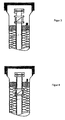
- a riser 1 is connected at its lower end to a horizontal line, which is not shown here, but which is part of a municipal district heating network. This heating network leads hot water.
- the riser 1 has at its upper end a valve 2.
- a valve 2 This is constructed as follows: It contains a valve disk, which extends for example in the horizontal direction and which is vertically movable up and down. In this case, the valve disk is held in the closed position by a spring, not shown here. The spring acts from bottom to top, and the closed position of the valve disc is thus in an upper position. This can be pressed against the force of the spring in a lower position, and is thus in an open position.
- the riser is surrounded by a jacket tube 3.
- the jacket tube 3 has a substantially larger diameter, so that between the outer surface of the riser 1 and the inner surface of the jacket tube 3, an annular space remains.
- two ring seals 4, 5 are provided in the annular space. These are rings made of an elastic material, such as rubber. Each ring is compressible (compressible) in the axial direction, for example, by two stainless steel plates, which are arranged on the two end faces, and which can be moved towards each other by means of clamping screws to compress the rubber ring. In an axial compression takes place a radial expansion of the rubber ring, so that this applies both inside the outer surface of the riser 1, and on the outside of the inner surface of the jacket tube 3. It thus takes a rich concern of the rubber ring on said surfaces instead.
- Another ring seal 5 is located further down, so that there is an axial distance between the two ring seals 4, 5.
- the jacket tube 3 is extended in its upper part. It carries a cap 7.
- the cap 7 is also made of plastic, as well as the casing 3.
- the cap 7 is screwed example of threaded connection and flat gasket on the casing tube 3 and sealed.
- the valve 2 is thus located in an interior which is limited by the cap 7, the upper part of the jacket tube 3 and the upper ring seal 4.
- This interior 14 is thus hermetically sealed against any influence from the outside.
- the upper ring seal 4 prevents ingress of water from above, while the lower ring seal 5 protects against water rising from below.
- FIG. 2 one recognizes a pipe bend 8. This is connected above the flange 13 to the jacket tube 1. The connection takes place only for actuating the valve 2 for the purpose of aeration, venting and emptying. Duct 8 is connected to the valve 2 with a lower flange 8.1.
- an actuating key 9 is mounted vertically displaceable - see the sealing bearing 10th
- an alarm system This consists of conductor wires 11. At the upper end of the conductor wires 11 there is a connection possibility 12 to which, for example, a monitoring device can be connected. In addition, this connection option 12 provides an additional measuring point for more accurate monitoring.
- the conductor wires 11 are generally guided down to the said horizontal pipe section, not shown, and is part of a control and signaling system of the entire pipeline network.
- the valve 2 is closed in the normal operating state. For example, in its upper position, the valve abuts against a seat, pressed by the force of said spring and by the instantaneous operating pressure. The riser is thus shut off at the top.
- the pipe bend 8 with its actuating key 9 is not mounted.
- the closure cap 7 and the blind flange 13.1 are dismantled. Thereafter, the lower flange 8.1 of the pipe elbow 8 is screwed to the flange 13 of the valve 2. To the upper flange 8.2 of the elbow 8, a hose is connected, as already mentioned.
- the actuating key 9 is moved down until it reaches the flap of the valve 2, which he then presses down, for example, and thus in the open position. Now, air exits upwards through the pipe bend 8. The valve 2 is held in the open position until no more air comes, but the operating medium. Then, the operating key 9 is brought out again upwards, so that the valve 2 closes by the force of the springs. In addition, a positive closure can be brought about with the actuating key 9.
- piping network may also carry other media than those mentioned here, for example cold water or oil.
Landscapes
- Engineering & Computer Science (AREA)
- General Engineering & Computer Science (AREA)
- Mechanical Engineering (AREA)
- Physics & Mathematics (AREA)
- Thermal Sciences (AREA)
- Chemical & Material Sciences (AREA)
- Combustion & Propulsion (AREA)
- Pipe Accessories (AREA)
- Absorbent Articles And Supports Therefor (AREA)
- External Artificial Organs (AREA)
- Pipeline Systems (AREA)
Priority Applications (1)
| Application Number | Priority Date | Filing Date | Title |
|---|---|---|---|
| PL07725063T PL2018500T3 (pl) | 2006-05-12 | 2007-05-10 | Urządzenie do odpowietrzania lub przewietrzania lub opróżniania sieci rurociągów |
Applications Claiming Priority (2)
| Application Number | Priority Date | Filing Date | Title |
|---|---|---|---|
| DE102006022195A DE102006022195B8 (de) | 2006-05-12 | 2006-05-12 | Vorrichtung zum Entlüften oder Belüften oder Entleeren eines Rohrleitungsnetzes |
| PCT/EP2007/004141 WO2007131698A2 (de) | 2006-05-12 | 2007-05-10 | Vorrichtung zum entlüften oder belüften oder entleeren eines rohrleitungsnetzes |
Publications (2)
| Publication Number | Publication Date |
|---|---|
| EP2018500A2 EP2018500A2 (de) | 2009-01-28 |
| EP2018500B1 true EP2018500B1 (de) | 2010-07-14 |
Family
ID=38320134
Family Applications (1)
| Application Number | Title | Priority Date | Filing Date |
|---|---|---|---|
| EP07725063A Not-in-force EP2018500B1 (de) | 2006-05-12 | 2007-05-10 | Vorrichtung zum entlüften oder belüften oder entleeren eines rohrleitungsnetzes |
Country Status (6)
| Country | Link |
|---|---|
| EP (1) | EP2018500B1 (pl) |
| AT (1) | ATE474178T1 (pl) |
| DE (2) | DE102006022195B8 (pl) |
| DK (1) | DK2018500T3 (pl) |
| PL (1) | PL2018500T3 (pl) |
| WO (1) | WO2007131698A2 (pl) |
Family Cites Families (3)
| Publication number | Priority date | Publication date | Assignee | Title |
|---|---|---|---|---|
| DE7229977U (de) * | 1972-11-02 | Kabel- Und Metallwerke Gutehoffnungshuette Ag | Schacht zur Aufnahme der Abzweig- oder Verbindungsstellen von Rohrleitungen | |
| SE510100C2 (sv) * | 1996-07-08 | 1999-04-19 | Heimo Hyvoenen | Fjärrvärmeanläggning med serviceenheter förlagda vid sidan om ett gatuplan |
| DE10027640C1 (de) * | 2000-06-06 | 2001-11-15 | Vatec Maschb Gmbh | Vorrichtung zum Be-und/oder Entlüften von Flüssigkeitsdruckleitungen sowie Verfahren zum Montieren eines Leitungsabschnittes |
-
2006
- 2006-05-12 DE DE102006022195A patent/DE102006022195B8/de not_active Expired - Fee Related
-
2007
- 2007-05-10 EP EP07725063A patent/EP2018500B1/de not_active Not-in-force
- 2007-05-10 PL PL07725063T patent/PL2018500T3/pl unknown
- 2007-05-10 AT AT07725063T patent/ATE474178T1/de active
- 2007-05-10 WO PCT/EP2007/004141 patent/WO2007131698A2/de not_active Ceased
- 2007-05-10 DK DK07725063.7T patent/DK2018500T3/da active
- 2007-05-10 DE DE502007004402T patent/DE502007004402D1/de active Active
Also Published As
| Publication number | Publication date |
|---|---|
| WO2007131698A2 (de) | 2007-11-22 |
| DE502007004402D1 (de) | 2010-08-26 |
| PL2018500T3 (pl) | 2010-12-31 |
| EP2018500A2 (de) | 2009-01-28 |
| DE102006022195B8 (de) | 2008-01-10 |
| DE102006022195B3 (de) | 2007-08-30 |
| WO2007131698A3 (de) | 2008-01-17 |
| ATE474178T1 (de) | 2010-07-15 |
| DK2018500T3 (da) | 2010-10-25 |
Similar Documents
| Publication | Publication Date | Title |
|---|---|---|
| EP0507127B1 (de) | Rohrweiche | |
| EP1277005A1 (de) | Rückflussverhinderer | |
| EP0892901B1 (de) | Sicherheitsfunktionselement für eine leitung | |
| EP0758619B1 (de) | Behälter zur Lagerung von Flüssigkeiten | |
| DE8914185U1 (de) | Kanalprüfgerät | |
| DE102006022195B3 (de) | Vorrichtung zum Entlüften oder Belüften oder Entleeren eines Rohrleitungsnetzes | |
| DE19533183C2 (de) | Schnellspannvorrichtung zur Kopplung einer Abgasleitung mit einem Auspuffrohr | |
| EP0990101B2 (de) | Verfahren zum transport von sauergas | |
| DE102011015819A1 (de) | Industriearmatur | |
| DE2358848A1 (de) | Ueberwachungseinrichtung fuer einen rohrleitungskompensator | |
| WO2007048549A1 (de) | Rohrverzweigungsanordnung | |
| DE3535586C2 (pl) | ||
| DE102011119458B4 (de) | Zwischenflanschrückschlagklappenvorrichtung | |
| DE102017107143A1 (de) | Trinkwasserbehälter und Verfahren zur Desinfektion von Legionellen | |
| DE102021125376A1 (de) | Ausgleichssystem, ausgeführt als pumpengesteuerte Druckhaltestation | |
| DE69709341T2 (de) | Temperierte, deformierbare Kupplung | |
| DE102018113566A1 (de) | Absperrvorrichtung zur Platzierung an der Außenseite einer verformbaren Leitung, System aus einem Kopplungsstück mit einer Absperrvorrichtung, und Verfahren zur Verwendung einer derartigen Absperrvorrichtung | |
| DE10156284B4 (de) | Absperrarmatur für einen Strömungswächter | |
| DE10101042A1 (de) | Vorrichtung zum stoßartigen Ausblasen von Druckluft zur Beseitigung von Materialanbackungen oder-aufstauungen | |
| DE3913800A1 (de) | Vorrichtung zur druckentlastung von geschlossenen, mit fluessigkeit gefuellten und mit waerme beaufschlagten raeumen | |
| DE1600707A1 (de) | Eck- oder durchgangsventil,insbesondere zur Verwendung in der Kerntechnik | |
| DE102008059109A1 (de) | Vorrichtung zum Verschließen oder Öffnen des Strömungsquerschnitts von Rohrleitungen, insbesondere in Vakuumanlagen | |
| DE102018113748B3 (de) | Tankventil und Tank mit einem derartigen Ventil | |
| WO2001025665A1 (de) | Dichtungsanordnung eines durch eine wand eines behälters durchgeführten rohres | |
| DE102010038000B4 (de) | Ventilvorrichtung und Spielvorrichtung mit einer Ventilvorrichtung |
Legal Events
| Date | Code | Title | Description |
|---|---|---|---|
| PUAI | Public reference made under article 153(3) epc to a published international application that has entered the european phase |
Free format text: ORIGINAL CODE: 0009012 |
|
| 17P | Request for examination filed |
Effective date: 20081009 |
|
| AK | Designated contracting states |
Kind code of ref document: A2 Designated state(s): AT BE BG CH CY CZ DE DK EE ES FI FR GB GR HU IE IS IT LI LT LU LV MC MT NL PL PT RO SE SI SK TR |
|
| DAX | Request for extension of the european patent (deleted) | ||
| GRAP | Despatch of communication of intention to grant a patent |
Free format text: ORIGINAL CODE: EPIDOSNIGR1 |
|
| GRAS | Grant fee paid |
Free format text: ORIGINAL CODE: EPIDOSNIGR3 |
|
| GRAA | (expected) grant |
Free format text: ORIGINAL CODE: 0009210 |
|
| AK | Designated contracting states |
Kind code of ref document: B1 Designated state(s): AT BE BG CH CY CZ DE DK EE ES FI FR GB GR HU IE IS IT LI LT LU LV MC MT NL PL PT RO SE SI SK TR |
|
| REG | Reference to a national code |
Ref country code: GB Ref legal event code: FG4D Free format text: NOT ENGLISH |
|
| REG | Reference to a national code |
Ref country code: CH Ref legal event code: EP |
|
| REG | Reference to a national code |
Ref country code: CH Ref legal event code: NV Representative=s name: SCHMAUDER & PARTNER AG PATENT- UND MARKENANWAELTE |
|
| REG | Reference to a national code |
Ref country code: IE Ref legal event code: FG4D |
|
| REF | Corresponds to: |
Ref document number: 502007004402 Country of ref document: DE Date of ref document: 20100826 Kind code of ref document: P |
|
| REG | Reference to a national code |
Ref country code: RO Ref legal event code: EPE |
|
| REG | Reference to a national code |
Ref country code: DK Ref legal event code: T3 |
|
| REG | Reference to a national code |
Ref country code: NL Ref legal event code: VDEP Effective date: 20100714 |
|
| LTIE | Lt: invalidation of european patent or patent extension |
Effective date: 20100714 |
|
| REG | Reference to a national code |
Ref country code: HU Ref legal event code: AG4A Ref document number: E008717 Country of ref document: HU |
|
| REG | Reference to a national code |
Ref country code: PL Ref legal event code: T3 |
|
| PG25 | Lapsed in a contracting state [announced via postgrant information from national office to epo] |
Ref country code: NL Free format text: LAPSE BECAUSE OF FAILURE TO SUBMIT A TRANSLATION OF THE DESCRIPTION OR TO PAY THE FEE WITHIN THE PRESCRIBED TIME-LIMIT Effective date: 20100714 Ref country code: LT Free format text: LAPSE BECAUSE OF FAILURE TO SUBMIT A TRANSLATION OF THE DESCRIPTION OR TO PAY THE FEE WITHIN THE PRESCRIBED TIME-LIMIT Effective date: 20100714 Ref country code: FI Free format text: LAPSE BECAUSE OF FAILURE TO SUBMIT A TRANSLATION OF THE DESCRIPTION OR TO PAY THE FEE WITHIN THE PRESCRIBED TIME-LIMIT Effective date: 20100714 |
|
| REG | Reference to a national code |
Ref country code: IE Ref legal event code: FD4D |
|
| PG25 | Lapsed in a contracting state [announced via postgrant information from national office to epo] |
Ref country code: SI Free format text: LAPSE BECAUSE OF FAILURE TO SUBMIT A TRANSLATION OF THE DESCRIPTION OR TO PAY THE FEE WITHIN THE PRESCRIBED TIME-LIMIT Effective date: 20100714 Ref country code: IS Free format text: LAPSE BECAUSE OF FAILURE TO SUBMIT A TRANSLATION OF THE DESCRIPTION OR TO PAY THE FEE WITHIN THE PRESCRIBED TIME-LIMIT Effective date: 20101114 Ref country code: BG Free format text: LAPSE BECAUSE OF FAILURE TO SUBMIT A TRANSLATION OF THE DESCRIPTION OR TO PAY THE FEE WITHIN THE PRESCRIBED TIME-LIMIT Effective date: 20101014 Ref country code: CY Free format text: LAPSE BECAUSE OF FAILURE TO SUBMIT A TRANSLATION OF THE DESCRIPTION OR TO PAY THE FEE WITHIN THE PRESCRIBED TIME-LIMIT Effective date: 20100714 Ref country code: PT Free format text: LAPSE BECAUSE OF FAILURE TO SUBMIT A TRANSLATION OF THE DESCRIPTION OR TO PAY THE FEE WITHIN THE PRESCRIBED TIME-LIMIT Effective date: 20101115 |
|
| PG25 | Lapsed in a contracting state [announced via postgrant information from national office to epo] |
Ref country code: GR Free format text: LAPSE BECAUSE OF FAILURE TO SUBMIT A TRANSLATION OF THE DESCRIPTION OR TO PAY THE FEE WITHIN THE PRESCRIBED TIME-LIMIT Effective date: 20101015 Ref country code: SE Free format text: LAPSE BECAUSE OF FAILURE TO SUBMIT A TRANSLATION OF THE DESCRIPTION OR TO PAY THE FEE WITHIN THE PRESCRIBED TIME-LIMIT Effective date: 20100714 Ref country code: LV Free format text: LAPSE BECAUSE OF FAILURE TO SUBMIT A TRANSLATION OF THE DESCRIPTION OR TO PAY THE FEE WITHIN THE PRESCRIBED TIME-LIMIT Effective date: 20100714 |
|
| PG25 | Lapsed in a contracting state [announced via postgrant information from national office to epo] |
Ref country code: IE Free format text: LAPSE BECAUSE OF FAILURE TO SUBMIT A TRANSLATION OF THE DESCRIPTION OR TO PAY THE FEE WITHIN THE PRESCRIBED TIME-LIMIT Effective date: 20100714 |
|
| PLBE | No opposition filed within time limit |
Free format text: ORIGINAL CODE: 0009261 |
|
| STAA | Information on the status of an ep patent application or granted ep patent |
Free format text: STATUS: NO OPPOSITION FILED WITHIN TIME LIMIT |
|
| PG25 | Lapsed in a contracting state [announced via postgrant information from national office to epo] |
Ref country code: IT Free format text: LAPSE BECAUSE OF FAILURE TO SUBMIT A TRANSLATION OF THE DESCRIPTION OR TO PAY THE FEE WITHIN THE PRESCRIBED TIME-LIMIT Effective date: 20100714 Ref country code: EE Free format text: LAPSE BECAUSE OF FAILURE TO SUBMIT A TRANSLATION OF THE DESCRIPTION OR TO PAY THE FEE WITHIN THE PRESCRIBED TIME-LIMIT Effective date: 20100714 Ref country code: SK Free format text: LAPSE BECAUSE OF FAILURE TO SUBMIT A TRANSLATION OF THE DESCRIPTION OR TO PAY THE FEE WITHIN THE PRESCRIBED TIME-LIMIT Effective date: 20100714 Ref country code: CZ Free format text: LAPSE BECAUSE OF FAILURE TO SUBMIT A TRANSLATION OF THE DESCRIPTION OR TO PAY THE FEE WITHIN THE PRESCRIBED TIME-LIMIT Effective date: 20100714 |
|
| 26N | No opposition filed |
Effective date: 20110415 |
|
| PG25 | Lapsed in a contracting state [announced via postgrant information from national office to epo] |
Ref country code: ES Free format text: LAPSE BECAUSE OF FAILURE TO SUBMIT A TRANSLATION OF THE DESCRIPTION OR TO PAY THE FEE WITHIN THE PRESCRIBED TIME-LIMIT Effective date: 20101025 |
|
| REG | Reference to a national code |
Ref country code: DE Ref legal event code: R097 Ref document number: 502007004402 Country of ref document: DE Effective date: 20110415 |
|
| BERE | Be: lapsed |
Owner name: GRUBER, GUIDO Effective date: 20110531 Owner name: SCHIRLE, ROSWITHA Effective date: 20110531 |
|
| PG25 | Lapsed in a contracting state [announced via postgrant information from national office to epo] |
Ref country code: MT Free format text: LAPSE BECAUSE OF FAILURE TO SUBMIT A TRANSLATION OF THE DESCRIPTION OR TO PAY THE FEE WITHIN THE PRESCRIBED TIME-LIMIT Effective date: 20100714 Ref country code: MC Free format text: LAPSE BECAUSE OF NON-PAYMENT OF DUE FEES Effective date: 20110531 |
|
| GBPC | Gb: european patent ceased through non-payment of renewal fee |
Effective date: 20110510 |
|
| PG25 | Lapsed in a contracting state [announced via postgrant information from national office to epo] |
Ref country code: BE Free format text: LAPSE BECAUSE OF NON-PAYMENT OF DUE FEES Effective date: 20110531 |
|
| PG25 | Lapsed in a contracting state [announced via postgrant information from national office to epo] |
Ref country code: GB Free format text: LAPSE BECAUSE OF NON-PAYMENT OF DUE FEES Effective date: 20110510 |
|
| PG25 | Lapsed in a contracting state [announced via postgrant information from national office to epo] |
Ref country code: LU Free format text: LAPSE BECAUSE OF NON-PAYMENT OF DUE FEES Effective date: 20110510 |
|
| PG25 | Lapsed in a contracting state [announced via postgrant information from national office to epo] |
Ref country code: TR Free format text: LAPSE BECAUSE OF FAILURE TO SUBMIT A TRANSLATION OF THE DESCRIPTION OR TO PAY THE FEE WITHIN THE PRESCRIBED TIME-LIMIT Effective date: 20100714 |
|
| REG | Reference to a national code |
Ref country code: FR Ref legal event code: PLFP Year of fee payment: 9 |
|
| PGFP | Annual fee paid to national office [announced via postgrant information from national office to epo] |
Ref country code: DE Payment date: 20150608 Year of fee payment: 9 Ref country code: CH Payment date: 20150522 Year of fee payment: 9 Ref country code: DK Payment date: 20150521 Year of fee payment: 9 Ref country code: RO Payment date: 20150525 Year of fee payment: 9 |
|
| PGFP | Annual fee paid to national office [announced via postgrant information from national office to epo] |
Ref country code: AT Payment date: 20150525 Year of fee payment: 9 Ref country code: FR Payment date: 20150521 Year of fee payment: 9 Ref country code: PL Payment date: 20150522 Year of fee payment: 9 Ref country code: HU Payment date: 20150601 Year of fee payment: 9 |
|
| REG | Reference to a national code |
Ref country code: DE Ref legal event code: R119 Ref document number: 502007004402 Country of ref document: DE |
|
| REG | Reference to a national code |
Ref country code: CH Ref legal event code: PL |
|
| REG | Reference to a national code |
Ref country code: DK Ref legal event code: EBP Effective date: 20160531 |
|
| REG | Reference to a national code |
Ref country code: AT Ref legal event code: MM01 Ref document number: 474178 Country of ref document: AT Kind code of ref document: T Effective date: 20160510 |
|
| PG25 | Lapsed in a contracting state [announced via postgrant information from national office to epo] |
Ref country code: LI Free format text: LAPSE BECAUSE OF NON-PAYMENT OF DUE FEES Effective date: 20160531 Ref country code: CH Free format text: LAPSE BECAUSE OF NON-PAYMENT OF DUE FEES Effective date: 20160531 Ref country code: RO Free format text: LAPSE BECAUSE OF NON-PAYMENT OF DUE FEES Effective date: 20160510 |
|
| PG25 | Lapsed in a contracting state [announced via postgrant information from national office to epo] |
Ref country code: AT Free format text: LAPSE BECAUSE OF NON-PAYMENT OF DUE FEES Effective date: 20160510 |
|
| REG | Reference to a national code |
Ref country code: FR Ref legal event code: ST Effective date: 20170131 |
|
| PG25 | Lapsed in a contracting state [announced via postgrant information from national office to epo] |
Ref country code: DE Free format text: LAPSE BECAUSE OF NON-PAYMENT OF DUE FEES Effective date: 20161201 Ref country code: FR Free format text: LAPSE BECAUSE OF NON-PAYMENT OF DUE FEES Effective date: 20160531 Ref country code: HU Free format text: LAPSE BECAUSE OF NON-PAYMENT OF DUE FEES Effective date: 20160511 |
|
| PG25 | Lapsed in a contracting state [announced via postgrant information from national office to epo] |
Ref country code: DK Free format text: LAPSE BECAUSE OF NON-PAYMENT OF DUE FEES Effective date: 20160531 |
|
| PG25 | Lapsed in a contracting state [announced via postgrant information from national office to epo] |
Ref country code: PL Free format text: LAPSE BECAUSE OF NON-PAYMENT OF DUE FEES Effective date: 20160510 |