EP2018317B1 - Isolierung einer flugzeugrumpfstruktur - Google Patents
Isolierung einer flugzeugrumpfstruktur Download PDFInfo
- Publication number
- EP2018317B1 EP2018317B1 EP07724269A EP07724269A EP2018317B1 EP 2018317 B1 EP2018317 B1 EP 2018317B1 EP 07724269 A EP07724269 A EP 07724269A EP 07724269 A EP07724269 A EP 07724269A EP 2018317 B1 EP2018317 B1 EP 2018317B1
- Authority
- EP
- European Patent Office
- Prior art keywords
- insulating mat
- fastening
- mat
- insulating
- foil
- Prior art date
- Legal status (The legal status is an assumption and is not a legal conclusion. Google has not performed a legal analysis and makes no representation as to the accuracy of the status listed.)
- Not-in-force
Links
- 238000009413 insulation Methods 0.000 title claims description 32
- 239000011888 foil Substances 0.000 claims abstract description 63
- 125000006850 spacer group Chemical group 0.000 claims abstract description 35
- 239000000463 material Substances 0.000 claims description 7
- 238000007665 sagging Methods 0.000 claims description 3
- 239000004642 Polyimide Substances 0.000 claims description 2
- 239000004721 Polyphenylene oxide Substances 0.000 claims description 2
- 239000006260 foam Substances 0.000 claims description 2
- 229920000570 polyether Polymers 0.000 claims description 2
- 229920001721 polyimide Polymers 0.000 claims description 2
- 239000004952 Polyamide Substances 0.000 abstract 1
- 229920002647 polyamide Polymers 0.000 abstract 1
- 102100040428 Chitobiosyldiphosphodolichol beta-mannosyltransferase Human genes 0.000 description 40
- 230000006835 compression Effects 0.000 description 8
- 238000007906 compression Methods 0.000 description 8
- 230000005540 biological transmission Effects 0.000 description 6
- 230000015572 biosynthetic process Effects 0.000 description 5
- 238000000034 method Methods 0.000 description 5
- 241000218642 Abies Species 0.000 description 4
- 230000000694 effects Effects 0.000 description 3
- 239000002657 fibrous material Substances 0.000 description 3
- 239000011152 fibreglass Substances 0.000 description 2
- -1 for example Substances 0.000 description 2
- 239000011491 glass wool Substances 0.000 description 2
- 238000009434 installation Methods 0.000 description 2
- 101100491335 Caenorhabditis elegans mat-2 gene Proteins 0.000 description 1
- 238000010276 construction Methods 0.000 description 1
- 238000011109 contamination Methods 0.000 description 1
- 239000013039 cover film Substances 0.000 description 1
- 230000003292 diminished effect Effects 0.000 description 1
- 230000005284 excitation Effects 0.000 description 1
- 239000004744 fabric Substances 0.000 description 1
- 229920002457 flexible plastic Polymers 0.000 description 1
- 238000007689 inspection Methods 0.000 description 1
- 239000011810 insulating material Substances 0.000 description 1
- 239000012774 insulation material Substances 0.000 description 1
- 230000035515 penetration Effects 0.000 description 1
- 239000004033 plastic Substances 0.000 description 1
- 229920003023 plastic Polymers 0.000 description 1
- XLYOFNOQVPJJNP-UHFFFAOYSA-N water Chemical compound O XLYOFNOQVPJJNP-UHFFFAOYSA-N 0.000 description 1
Images


Classifications
-
- B—PERFORMING OPERATIONS; TRANSPORTING
- B64—AIRCRAFT; AVIATION; COSMONAUTICS
- B64C—AEROPLANES; HELICOPTERS
- B64C1/00—Fuselages; Constructional features common to fuselages, wings, stabilising surfaces or the like
- B64C1/40—Sound or heat insulation, e.g. using insulation blankets
-
- B—PERFORMING OPERATIONS; TRANSPORTING
- B64—AIRCRAFT; AVIATION; COSMONAUTICS
- B64C—AEROPLANES; HELICOPTERS
- B64C1/00—Fuselages; Constructional features common to fuselages, wings, stabilising surfaces or the like
- B64C1/40—Sound or heat insulation, e.g. using insulation blankets
- B64C1/403—Arrangement of fasteners specially adapted therefor, e.g. of clips
Definitions
- the present invention generally pertains to the technical field of acoustics.
- the invention specifically pertains to a specially designed insulating mat for insulating an aircraft fuselage structure relative to the passenger cabin or the cargo compartment formed by said aircraft fuselage structure in acoustic and partly also in thermic respects.
- the inside of an aircraft fuselage is frequently lined with insulating mats of glass wool.
- the insulating mats line the fuselage frames as well as the frame panels situated between the individual frames including the stringers.
- the insulation is fastened on the frame panels as well as on the frames that laterally border the frame panels with the aid of fir tree-shaped fastening needles and fastening disks pressed thereon as illustrated in an exemplary fashion in Figure 1 .
- the insulation is substantially compressed in the region of the fastening needles in this fastening method such that the cover foils of the insulating mats are compressed or contracted.
- the cover foil of the insulating mats is stretched over the disks fastened on the fastening needles such that the cover foil is disadvantageously subjected to vibrations originating from the aircraft fuselage via the fastening needles and the disks.
- the thusly induced vibrations are emitted in the form of noise waves via the funnel that results from the compression of the cover foil and is clearly visible in Figure 1 similar to a loudspeaker such that the noise contamination may increase.
- Figure 1 furthermore shows that the insulating mat is substantially compressed in the region of the frames such that undesirable acoustic and thermal bridges are also created at these locations.
- US 6,358,591 B1 describes a fire-blocking insulation blanket containing fire-blocking materials for preventing rapid penetration of fire into an aircraft fuselage in case of a fire outside the aircraft.
- the insulation blanket contains at least one layer of fiber glass or other thermo-acoustic insulation material.
- the present invention aims, among other things, to disclose an improved insulating structure with fewer acoustic bridges.
- the objective forming the basis thereof is attained with an insulating mat according to claim 1 that is specially designed for the acoustic insulation of an aircraft fuselage structure composed of frames and stringers extending transverse to the frames.
- the inventive insulating mat features a multitude of fastening clips that are fixed on a first surface of the insulating mat and laterally protrude over the border of the insulating mat.
- first surface refers to the side of the insulating mat that faces away from the passenger cabin or the cargo compartment in the installed state of the insulating mat.
- the insulating mat can be fastened on the frames by providing the insulating mats with fastening clips on two edge regions that lie opposite of one another.
- fastening clips on two edge regions that lie opposite of one another.
- punctiform fastening clips or strip-shaped fastening clips that extend in the insulating mat over the entire lateral border thereof may be used.
- the fastening clips laterally protrude over the lateral border of the insulating mat, it can be ensured that the insulating mat can be fastened to a fuselage structure, particularly the frames, by means of these fastening clips without affecting the insulating mat itself.
- the insulating mat may be arranged in a frame panel, wherein the fastening clips of the first surface are positioned on the frames bordering the frame panel and fastened thereto. This makes it possible to simultaneously eliminate the acoustic weak point in the form of the gap resulting between the frame insulating mat and the panel insulating mat if the insulating mat is conventionally installed.
- This structure may further allow an uncomplicated inspection of the electric lines that are frequently installed above the frame insulation with the aid of cable clamps such that the lines laterally extend along the frames, namely because the lateral edge of the insulating mat that laterally protrudes toward the frame can be simply folded away without having to uninstall the clips.
- the inventive insulating mat is coated with a thin layer such as, for example, a foil on a second surface intended to point in the direction of the passenger cabin or cargo compartment (in this context, the term second surface refers to the side of the insulating mat that lies opposite of the initially mentioned first surface), wherein this thin layer absorbs the tension exerted upon the insulating mat by the fastening means and thusly prevents sagging of the insulating mats.
- a thin layer such as, for example, a foil on a second surface intended to point in the direction of the passenger cabin or cargo compartment (in this context, the term second surface refers to the side of the insulating mat that lies opposite of the initially mentioned first surface), wherein this thin layer absorbs the tension exerted upon the insulating mat by the fastening means and thusly prevents sagging of the insulating mats.
- the foil-like layer is at least regionally provided with holes.
- Such a perforation in which the percentage of holes may exceed 30%, makes it possible to ensure that only little sound is emitted, if any, in case the foil-like layer is undesirably excited to vibrate.
- the insulating mat may also be coated with a netting on its second surface in order to transmit the forces exerted upon the insulating mat by the fastening means.
- the netting may consist of crisscrossing threads that may form triangular, quadrangular or polygonal mesh structures.
- the insulating mat itself may consist of a fiber material such as, for example, glass wool that can act hygroscopically at correspondingly high relative humidities
- the inventive insulating mat is furthermore coated with an impervious cover film because water vapor naturally is able to penetrate the aforementioned perforated foil or netting, respectively.
- the aforementioned impervious cover foil is arranged such that the layer provided with holes lies between the cover foil and the insulating mat.
- the entire insulating mat including the perforated foil may be alternatively packed into and covered by such a cover foil.
- the cover foil is at least regionally realized in a deformable fashion around the fastening points independently of the layer provided with holes.
- the insulating mat including the applied perforated foil may, for example, be slightly compressed in the region of the fastening points, whereas the cover foil does not participate in this deformation around the tubular spacers, but rather remains in its original undeformed state and at least tends to preserve this state. Consequently, it can be ensured that the sound-deadening perforated foil does not lie on the cover foil in the region of the fastening points such that no structure-borne noise can be transmitted between these two foils.
- the cover foil may be provided, for example, with a bulge in the region around the fastening points, wherein said bulge is lifted off the insulating mat such that a hill-like elevation is created.
- the cover foil comes in contact with the layer provided with holes in the immediate vicinity of the fastening points in this particular embodiment, this actually applies to only the immediate vicinity of the fastening points because the hill-shaped bulge of the cover foil protrudes inward in the direction of the layer provided with holes in a crater-shaped fashion within these regions and therefore contacts this layer provided with holes.
- the cover foil is spaced apart from the layer provided with holes such that no transmission of structure-borne sound can take place in this region.
- the inventive insulating mat in the panel region features a multitude of tubular spacers and a corresponding number of through-openings, into which the tubular spacers are fitted such that the insulating mat can be attached to the aircraft fuselage structure through the tubular spacers with the aid of suitable fastening means.
- the tubular spacers serve as a through-opening, through which a corresponding fastening means for fastening the insulating mat on the aircraft fuselage structure can extend.
- the tubular spacers furthermore act as a resistance element that is intended to prevent the insulating mat from being compressed.
- the tubular spacers are realized more rigid in the direction of their through-opening than the insulating mat is perpendicular to its surface such that the insulating mat itself may not be compressed as substantially as it would be the case without the spacers that act as resistance elements, for example, when a fastening disk is pushed on the corresponding fastening means in order to attach the insulting mat to an aircraft fuselage structure.
- the tubular spacers may be made, for example, of a foamed material such as, e.g., polyimide or polyether foam.
- a foamed material such as, e.g., polyimide or polyether foam.
- fastening means can be guided through the tubular spacers in order to fasten the insulating mat on an aircraft fuselage structure and be fastened with a higher counterforce to the aircraft fuselage structure, namely without excessively deforming the insulating mat such that the formation of the aforementioned funnels with loudspeaker effect can be diminished.
- the insulating mat can be fastened in the panel region of the mat, for example, on the stringers of an aircraft fuselage structure.
- the above-described laterally protruding fastening clips serve for fastening the edge regions such that the insulating mats entirely can be installed without creating acoustic bridges.
- a fastening means is disclosed that is specially designed for fastening an insulating mat on an aircraft fuselage structure, for example, on a frame or a stringer.
- the fastening means is designed such that it is impossible to excessively compress the insulating mat so as to prevent the above-described undesirable excessive impression of funnels into the surface of the insulating mat.
- the fastening means comprises a linear, i.e. straight, shaft with a first end and a second end.
- the shaft On its first end, the shaft is provided with a fastening element for attaching the shaft to an aircraft fuselage structure in such a way that the shaft protrudes from the aircraft fuselage structure in order to penetrate or extend through an insulating mat.
- the shaft In the region of the second end that lies opposite of the first end, the shaft features a limit stop that prevents an abutment element such as, for example, the aforementioned fastening disk for fastening an insulating mat from being pushed or screwed onto the shaft farther than the limit stop. Consequently, the limit stop restricts the movement of an abutment element on the shaft in the direction of the first end.
- the limit stop element may be, for example, of a flange that surrounds the shaft in a collar-like fashion such that an abutment element, for example, a fastening disk, can only be pushed or screwed onto the shaft up to the limit stop.
- the limit stop therefore prevents a fastening disk from being pushed onto the shaft farther than the limit stop such that the insulating mat may only be compressed as far as permitted by the limit stop when the insulating mat is fastened by means of such a fastening disk.
- the shaft can have an arrangement at its second end, the arrangement having a multitude of barb elements which are adapted to secure an abutment element such as for example a fastening disk for fastening an insulation mat on the shaft.
- an abutment element such as for example a fastening disk can be easily slid on to the second end of the shaft until it abuts the limit stop wherein the barb elements prevent an undesired releasing of the abutment elements from the shaft.
- the fastening element that may be realized, for example, in the form of a clamp designed for being attached to a stringer.
- a shaft can be fastened on a stringer by means of the clamp such that the insulating mats can be subsequently attached thereto.
- the fastening means or the shafts of the fastening means may be initially inserted through the corresponding tubular spacers of the insulating mats and fastened thereon such that the insulating mats provided with the fastening means in this manner can be subsequently fastened on an aircraft fuselage structure with the aid of the fastening means by simply pushing the clamps of the fastening elements on the stringers.
- the objective forming the basis thereof may be attained with an insulating kit for the sound insulation of an aircraft fuselage structure that is composed of frames and stringers extending transverse to the frames, wherein said insulating kit comprises at least one insulating mat of the above-described type, as well as at least one fastening means of the type described in connection with the aforementioned methods.
- the aircraft fuselage structure consists of stringers 3 that extend in the longitudinal direction of an aircraft fuselage and frames 4 that carry the stringers 3 and extend perpendicular thereto.
- the aircraft fuselage structure is insulated by means of panel insulation 1 in the form of an insulating mat 1 in the frame panels situated between the respective frames 4.
- the frames 4 are also insulated with the aid of insulating mats 2 that are wound around the frames 4 and fastened thereon with the aid of suitable fastening means 5.
- the panel insulation 1 is installed with fastening means 5 in the form of so-called "fir trees" 5, i.e., fir tree-shaped fastening needles, that are attached to the stringers 3.
- the panel insulation 1 is also substantially compressed in the region of the frames 4 such that undesirable acoustic bridges are also created at these locations due to the compression of the insulating mat 1.
- the present invention aims to disclose a sound insulation for an aircraft fuselage structure , 3, 4 of the type illustrated in the central frame panel in Figure 2 .
- the panel insulation 1 is not compressed anywhere, i.e., it lies completely relaxed in the frame panel and toward the frame also overlaps the frame insulation such that acoustic bridges are prevented at these locations as well.
- the present invention proposes an insulating mat as well as its individual components as illustrated in Figures 3 to 7 .
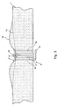
- FIG 3 shows an insulating mat according to the invention with an inventive insulating mat 1 as well as a fastening means 8 in the form of a cross-sectional representation.
- the insulating mat 1 consists of a fiber material such as, for example, a non-woven fiber glass fabric.
- the inventive insulating mat 1 features a multitude of through-openings 9, into which tubular spacers 10 are fitted such that the insulating mat 1 can be attached through the tubular spacers 10 to an aircraft fuselage structure with the aid of suitable fastening means 8. Only one through-opening 9 and one tubular spacer 10 fitted therein are illustrated in the detail according to Figure 3 .
- the tubular spacer 10 has a longitudinal dimension that extends in the direction of its through-opening that essentially corresponds to the thickness of the insulating mat 1 such that the spacer 10 ends flush with the two opposite surfaces of the insulating mat 1.
- the fastening means 8 can be inserted through the through-opening of the spacer 10 such that the insulating mat 1 can be fixed on the shaft 11 of the fastening means 8 with the aid of a fastening disk 6 that can be attached to the shaft 11 of the fastening means 8.
- the tubular spacers 10 are realized more rigidly than the insulating mat 1 itself in the direction of their through-openings such that the insulating mat 1 can only be deformed slightly when the fastening disk 6 is attached to the shaft 11 of the fastening means 8.
- the tubular spacer 10 may be made, for example, of a foamed material with a higher modulus of elasticity than the insulating mat 1.
- the shaft 11 is surrounded at its free end in a collar-like fashion by a flange 12 that is intended as a limit stop for the fastening disk 6 such that the fastening disk 6 can only be pushed on the shaft 11 until it comes in contact with the flange 12.
- the compression of the insulating mat 1 and therefore the formation of acoustic bridges can be prevented in this fashion.
- the insulating mat 1 is coated with an impervious cover foil 14 in these regions such that the perforated foil 13 lies between this cover foil 14 and the insulating mat 1 as illustrated in Figure 3 .
- the cover foil 14 features a bulge in the region around the through-openings 9 and in the regions in which the insulating mat 1 is provided with a perforated foil 13, wherein said bulge makes it possible for the cover foil 14 to deform independently of the foil 13 provided with holes in the region around the through-openings.
- a bulge is illustrated in Figure 3 .
- the fastening means 8 features a clamp 15 on the end that lies opposite of the flange 12, wherein the insulating mat 1 can be simply attached to a stringer 3 by means of said clamp.
- the installation may naturally also be carried out such that the fastening means 8 are initially attached to the stringers 3 by means of the clamps 15 and an insulating mat 1 is subsequently attached to the fastening means 5 or their shafts 11, respectively, in order to be subsequently fixed on the fastening means 8 with the aid of fastening disks 6.
- Figure 4 shows another embodiment of the inventive insulating mat.
- This second embodiment can only be distinguished from the above-described first embodiment in that the perforated foil 13 is realized in the form of a netting 16 in this case, and by the formation of the cover foil 14.
- a netting 16 is applied to the insulating mat 1 in the deformed state in the second embodiment according to Figure 4 instead of the perforated foil 13, as shown in Figure 4 .
- the insulating mat 1 is deformed in such a way that the surface of the insulating mat is slightly compressed in a trough-like fashion in the region around the tubular spacer 10 such that the spacer 10 slightly protrudes over the first surface of the insulating mat 1.
- the netting 16 is applied on this first surface in the deformed configuration of the insulating mat 1 and connected to the insulating mat as well as to the spacers 10 such that the deformed configuration of insulating mat 1 is permanently preserved due to the attachment of the netting 16 to the spacers 10.
- an impervious cover foil 14 is applied over the entire surface of the insulating mat 1 such that the cover foil 10 spans the trough created due to the compression of the insulating mat 1.
- the cover foil 14 is also decoupled from the netting 16 in this second embodiment such that no sound transmission caused by structure-borne sound can take place.
- the fastening of the insulating mat 1 in the edge region is described below with reference to Figures 5 to 7 .
- the insulating mat 1 is equipped with a multitude of fastening clips 17 that are arranged on the surface of the insulating mat 1 that lies opposite of the surface coated with the perforated foil 13.
- the fastening clips 17 protrude over the lateral border of the insulating mat 1 such that the insulating mat 1 can be fastened at the desired location such as, for example, a frame 2 with the aid of the clips I7 as illustrated in Figure 7 .
- the fastening clips 17 may be, for example, of flexible plastic strips that can be slightly bent during to fastening process so as to adapt the plastic strips to predefined geometries.
- the fastening clips 17 are provided with corresponding holes, through which fastening elements 8 can be inserted.
- the fastening clip 17 is bent at this location such that its fastening hole lies on the lateral edge of the insulating mat 1 such that the insulating mat 1 can be fastened on the frame 2 together with the fastening for the frame insulation 2 by means of the fastening clips 17. Due to these measures, the panel insulation 1 in the form of an inventive insulating mat 1 overlaps the frame insulation 2 such that the panel insulation 1 does not have to be compressed in the frame region whereby the formation of undesirable acoustic bridges is prevented.
- the present invention for the first time proposes an insulating mat for the sound insulation of aircraft fuselage constructions that makes it possible to largely prevent undesirable acoustic bridges.
Landscapes
- Engineering & Computer Science (AREA)
- Mechanical Engineering (AREA)
- Aviation & Aerospace Engineering (AREA)
- Soundproofing, Sound Blocking, And Sound Damping (AREA)
- Connection Of Plates (AREA)
- Vehicle Interior And Exterior Ornaments, Soundproofing, And Insulation (AREA)
- Building Environments (AREA)
- Insulating Bodies (AREA)
Claims (7)
- Isoliermatte (1) zur Schallisolierung einer aus Spanten (4) und quer zu den Spanten (4) verlaufenden Stringern (3) gebildeten Flugzeugrumpfstruktur, wobei die Isoliermatte (1) aufweist:eine Mehrzahl an Befestigungslaschen (17), welche als Befestigungsmittel zum Befestigen von Randbereichen der Isoliermatte an Spanten der Flugzeugrumpfstruktur dienen, wobei die Befestigungslaschen (1) an einer ersten Oberfläche der Isoliermatte (1) befestigt sind und über die Berandung der Isoliermatte (1) seitlich hinausragen, undeine mit Löchern versehene Schicht (13), mit der eine zweite Oberflächenseite der Isoliermatte (1) zumindest in einem Bereich um ihre Befestigungsstellen, wo die Matte durch Befestigungsmittel (8) durch Durchgangslöcher (9) in der Matte (1) an den Stringern (3) zu befestigen ist, herum beschichtet ist, wobei die Schicht dazu angepasst ist, Spannung, die durch die Befestigungsmittel auf die Isoliermatte ausgeübt wird, wenn sie an den Stringern befestigt ist, um ein Durchhängen der Isoliermatte zu verhindern, zu absorbieren,eine undurchlässige Deckfolie (14) die derart angeordnet ist, dass die mit Löchern versehene Schicht (13) zwischen der Deckfolie (14) und der Isoliermatte (1) liegt,wobei die Deckfolie (14) bereichsweise von der mit Löchern versehenen Schicht (13) entkoppelt ist, so dass die Deckfolie (14) in dem Bereich um die Durchgangsöffnungen (9) herum unabhängig von der mit Löchern versehenen Schicht (13) verformt werden kann.
- Isoliermatte nach Anspruch 1,
wobei die mit Löchern versehene Schicht als Lochfolie (13) ausgebildet ist. - Isoliermatte nach Anspruch 1,
wobei die mit Löchern versehene Schicht als Netz (16) ausgebildet ist. - Isoliermatte nach einem der Ansprüche 1 bis 3,
wobei die Deckfolie (14) im Bereich um die Befestigungsstellen der Isoliermatte (1) mit einer Auswölbung versehen ist, welche sich von der Isoliermatte (1) abhebt. - Isoliermatte nach einem der Ansprüche 1 bis 4, ferner aufweisend:eine Vielzahl an rohrförmigen Abstandhaltern (10),wobei die Isoliermatte (1) eine Vielzahl an Durchgangsöffnungen (9) aufweist, in welche die rohrförmigen Abstandhalter (10) so eingepasst sind, dass die Isoliermatte (1) durch die rohrförmigen Abstandhalter (10) hindurch mittels geeigneter Befestigungsmittel (8) an der Flugzeugrumpfstruktur (3, 4) anbringbar ist.
- Isoliermatte nach Anspruch 5,
wobei die rohrförmigen Abstandhalter (10) in Richtung ihrer Durchgangsöffnung (9) betrachtet steifer sind als die Isoliermatte (1) senkrecht zu ihrer Oberfläche. - Isoliermatte nach Anspruch 5 oder 6,
wobei die rohrförmigen Abstandhalter (10) aus einem Schaumwerkstoff, insbesondere aus Polyimid oder Polyetherschaum, gefertigt sind.
Applications Claiming Priority (3)
| Application Number | Priority Date | Filing Date | Title |
|---|---|---|---|
| US74747006P | 2006-05-17 | 2006-05-17 | |
| DE102006023209A DE102006023209A1 (de) | 2006-05-17 | 2006-05-17 | Isolierung einer Flugzeugrumpfstruktur |
| PCT/EP2007/003331 WO2007131583A1 (en) | 2006-05-17 | 2007-04-16 | Insulation of an aircraft fuselage structure |
Publications (2)
| Publication Number | Publication Date |
|---|---|
| EP2018317A1 EP2018317A1 (de) | 2009-01-28 |
| EP2018317B1 true EP2018317B1 (de) | 2012-02-29 |
Family
ID=38607918
Family Applications (1)
| Application Number | Title | Priority Date | Filing Date |
|---|---|---|---|
| EP07724269A Not-in-force EP2018317B1 (de) | 2006-05-17 | 2007-04-16 | Isolierung einer flugzeugrumpfstruktur |
Country Status (10)
| Country | Link |
|---|---|
| US (1) | US8308103B2 (de) |
| EP (1) | EP2018317B1 (de) |
| JP (1) | JP2009537362A (de) |
| CN (1) | CN101443232B (de) |
| AT (1) | ATE547321T1 (de) |
| BR (1) | BRPI0711590A2 (de) |
| CA (1) | CA2648858A1 (de) |
| DE (1) | DE102006023209A1 (de) |
| RU (1) | RU2429162C2 (de) |
| WO (1) | WO2007131583A1 (de) |
Cited By (1)
| Publication number | Priority date | Publication date | Assignee | Title |
|---|---|---|---|---|
| US11952102B2 (en) | 2021-04-28 | 2024-04-09 | Airbus Operations Gmbh | Textile door insulation means for a passenger door in an aircraft |
Families Citing this family (34)
| Publication number | Priority date | Publication date | Assignee | Title |
|---|---|---|---|---|
| FR2933376B1 (fr) * | 2008-07-07 | 2011-12-09 | Airbus France | Dispositif de fixation de matelas isolants et procede de pose de matelas isolants dans un fuselage d'aeronef |
| DE102008037143A1 (de) * | 2008-08-08 | 2010-02-11 | Airbus Deutschland Gmbh | Isolationsaufbau zum thermischen und akustischen Isolieren eines Luftfahrzeugs |
| DE102009006578B4 (de) | 2009-01-29 | 2014-05-22 | Airbus Operations Gmbh | Fahrzeug mit einer Kabine mit Isolierungspaketen und mindestens einem Befestigungselement und Verfahren zum Befestigen von Isolierungspaketen |
| DE102009015590A1 (de) * | 2009-03-30 | 2010-10-07 | Airbus Deutschland Gmbh | Luftfahrzeug mit einem Isolierungssystem zur Wärme- und Schallisolierung |
| DE102009030037A1 (de) * | 2009-06-23 | 2010-12-30 | Airbus Operations Gmbh | Isolierungspaket für die Isolierung einer Kabine eines Fahrzeugs |
| FR2955084B1 (fr) * | 2010-01-12 | 2012-06-08 | Airbus Operations Sas | Aeronef comportant au moins un filet destine a reduire le bruit aerodynamique d'un element structurel dudit aeronef |
| DE102010006564B4 (de) * | 2010-02-02 | 2016-01-28 | Airbus Operations Gmbh | Kondenswasserdurchtritt verringerndes Isolierpaket zum thermischen und akustischen Isolieren einer Fahrzeugkabine sowie Verwendung eines Isolierstücks an einem Isolierpaket und Flugzeug mit einem Isolierpaket |
| US9017789B2 (en) * | 2010-10-12 | 2015-04-28 | Amsafe Bridport Limited | Insulation assemblies for engine housings and associated methods of use and manufacture |
| DE102010051654B4 (de) * | 2010-11-17 | 2014-09-25 | Airbus Operations Gmbh | Isolierungsanordnung in einem Luftfahrzeug |
| DE102010052671B4 (de) * | 2010-11-26 | 2017-03-23 | Airbus Operations Gmbh | Isolierungsanordnung mit Ventilationsöffnungen für Luftfahrzeuge |
| US8899519B2 (en) | 2011-03-15 | 2014-12-02 | The Boeing Company | Method and system for insulating frame member |
| US8662448B2 (en) * | 2011-06-06 | 2014-03-04 | The Boeing Company | System and method for insulating frame member |
| FR2984846B1 (fr) | 2011-12-21 | 2014-01-24 | Airbus Operations Sas | Dispositif d'isolation standardise pour aeronef et procedes de fabrication et d'utilisation de celui-ci |
| FR3012111B1 (fr) * | 2013-10-17 | 2018-03-02 | Airbus Operations | Fuselage d'aeronef comprenant une isolation externe |
| FR3019599B1 (fr) * | 2014-04-08 | 2016-05-06 | Aircelle Sa | Agencement de fixation pour panneau de protection thermique |
| US9470257B2 (en) * | 2014-04-17 | 2016-10-18 | Nmc Group, Inc. | Fastener assembly for insulation blanket |
| FR3031082B1 (fr) * | 2014-12-30 | 2017-02-10 | Airbus Operations Sas | Ensemble de jonction raccordant un carenage ventral d'aeronef au fuselage pourvu d'un raidisseur en position particuliere |
| EP3127803B1 (de) * | 2015-08-04 | 2019-05-01 | Airbus Operations GmbH | Flugzeugisolierungssystem und flugzeugklimatisierungs- und -isolierungsanordnung |
| US10023286B2 (en) * | 2015-11-19 | 2018-07-17 | The Boeing Company | Aircraft bay blankets that provide enhanced drainage features |
| US10604224B2 (en) * | 2016-01-12 | 2020-03-31 | The Boeing Company | Aircraft bay blankets that provide enhanced drainage features |
| ITUA20161344A1 (it) * | 2016-03-04 | 2017-09-04 | Sky Tecno S R L | Sistema di fissaggio di pannelli isolanti su aeromobili. |
| US9988137B2 (en) * | 2016-03-29 | 2018-06-05 | The Boeing Company | Methods and apparatus for forming and installing insulation blankets in a vehicle compartment |
| FR3059062B1 (fr) * | 2016-11-22 | 2019-07-19 | Airbus Operations | Entretoise auto-perforante pour un matelas d'isolation d'aeronef, procede de pose de ladite entretoise et matelas d'isolation d'aeronef equipe de ladite entretoise |
| FR3061130B1 (fr) * | 2016-12-22 | 2021-07-02 | Airbus Operations Sas | Module d'isolation thermophonique pour aeronef comprenant un matelas et une structure porteuse, et procede d'isolation thermophonique d'un aeronef au moyen d'un tel module |
| US10513323B2 (en) * | 2017-01-06 | 2019-12-24 | The Boeing Company | Systems and methods for controlling moisture ingress in aircraft skin mounted electronics |
| US10814954B2 (en) * | 2017-01-17 | 2020-10-27 | The Boeing Company | Insulation system |
| US10532801B2 (en) * | 2017-01-17 | 2020-01-14 | The Boeing Company | Continuous insulation blanket cap strip assemblies and methods of using same |
| US10988230B2 (en) * | 2017-06-19 | 2021-04-27 | The Boeing Company | Passive moisture management bladder in an aircraft |
| US11858614B2 (en) * | 2018-03-02 | 2024-01-02 | The Boeing Company | Aircraft thermal acoustic insulation blanket |
| CZ307803B6 (cs) * | 2018-03-14 | 2019-05-15 | IzoDol s.r.o. | Sestava kotevního prvku pro zhotovení tvarované fasády, tvarovaná fasáda a způsob zhotovení tvarové fasády |
| US11091270B2 (en) | 2019-01-22 | 2021-08-17 | The Boeing Company | Buoyancy driven passive vehicle air drying system and method |
| CN112776977A (zh) * | 2019-11-01 | 2021-05-11 | 庞巴迪公司 | 热声隔离系统、模块及包括该热声隔离系统和模块的飞机 |
| US11320296B2 (en) | 2020-03-30 | 2022-05-03 | The Boeing Company | Test cage for testing a gap in a vehicle |
| GB202101873D0 (en) * | 2021-02-11 | 2021-03-31 | Lewis Stephen Desmond | Thermal protection for supersonic and space planes |
Citations (1)
| Publication number | Priority date | Publication date | Assignee | Title |
|---|---|---|---|---|
| FR1022731A (fr) * | 1950-08-01 | 1953-03-09 | Sncase | Procédé d'insonorisation et d'isolation thermique à structures absorbantes multiples et structures en permettant la mise en oeuvre |
Family Cites Families (27)
| Publication number | Priority date | Publication date | Assignee | Title |
|---|---|---|---|---|
| US2118998A (en) * | 1937-08-10 | 1938-05-31 | Boeing Aircraft Co | Interior trim for aircraft |
| US3712846A (en) * | 1971-06-23 | 1973-01-23 | Carpenter L & Co | Acoustical panel |
| US3895409A (en) * | 1973-08-31 | 1975-07-22 | Johns Manville | Spacer grommet and method of manufacture thereof |
| US4313524A (en) * | 1980-12-17 | 1982-02-02 | Rohr Industries, Inc. | Bulk acoustic absorber panels for use in high speed gas flow environments |
| US4441578A (en) * | 1981-02-02 | 1984-04-10 | Rohr Industries, Inc. | Encapsulated bulk absorber acoustic treatments for aircraft engine application |
| US4842465A (en) * | 1982-04-16 | 1989-06-27 | Ksm Fastening Systems Inc. | Insulation hanger with locking device |
| US4781503A (en) * | 1983-06-22 | 1988-11-01 | Sfs Stadler Ag | Fastener assembly for securing roofing on a soft insulation material to a solid base |
| US4926963A (en) * | 1987-10-06 | 1990-05-22 | Uas Support, Inc. | Sound attenuating laminate for jet aircraft engines |
| FR2658223A1 (fr) * | 1990-02-14 | 1991-08-16 | Axter | Couverture etanche fixee sur une charpente. |
| FR2685756B1 (fr) * | 1991-12-26 | 1994-04-08 | Aerospatiale Ste Nationale Indle | Procede de preparation d'un matelas d'isolation thermique et phonique et matelas d'isolation thermique et phonique ainsi prepare. |
| WO1993014999A1 (fr) * | 1992-01-22 | 1993-08-05 | Frigokit Europe | Procede et systeme pour l'isolation thermique d'enceintes de natures diverses |
| DE4208493C2 (de) * | 1992-03-17 | 1994-02-10 | Deutsche Aerospace Airbus | Halterung für eine Isoliermatte |
| WO1993019912A1 (en) * | 1992-04-02 | 1993-10-14 | Akro Fireguard Products, Inc. | Aircraft fuselage flame barrier |
| RU2022817C1 (ru) * | 1992-04-20 | 1994-11-15 | Ленинградский государственный аграрный университет | Устройство для защиты от солнечного излучения кабины транспортного средства |
| JPH06305489A (ja) * | 1993-04-27 | 1994-11-01 | Mitsubishi Heavy Ind Ltd | 内装・防音断熱部材取付方法 |
| US5472760A (en) * | 1993-06-25 | 1995-12-05 | W. L. Gore & Associates, Inc. | Vehicle insulation |
| US5426905A (en) * | 1993-09-13 | 1995-06-27 | The United States Of America As Represented By The Secretary Of The Navy | Insulation attachment stud for composite material substrate |
| DE19504463A1 (de) * | 1995-02-10 | 1996-08-14 | Hilti Ag | Befestigungselement für Isolationsmaterialien |
| US5811167A (en) * | 1996-01-25 | 1998-09-22 | W. L. Gore & Associates, Inc. | Packaged insulation and method of making same |
| RU2196074C2 (ru) * | 1999-03-12 | 2003-01-10 | Открытое акционерное общество Авиационный научно-технический комплекс им. А.Н.Туполева | Способ крепления теплозвукоизоляции к каркасу летательного аппарата |
| US6358591B1 (en) * | 1999-06-04 | 2002-03-19 | Orcon Corporation | Fire-blocking insulation blanket |
| JP3638889B2 (ja) | 2000-07-27 | 2005-04-13 | 大塚化学ホールディングス株式会社 | 誘電性樹脂発泡体及びそれを用いた電波レンズ |
| DE10041458C2 (de) * | 2000-08-23 | 2003-01-30 | Kaefer Isoliertechnik | Einrichtung zum Vermindern von Schallpegeln sowie Verkleidung in Flugzeugen, Fahrzeugen oder Schiffen |
| US20040131836A1 (en) | 2003-01-02 | 2004-07-08 | 3M Innovative Properties Company | Acoustic web |
| US8011619B2 (en) * | 2004-01-05 | 2011-09-06 | Airbus Deutschland Gmbh | Insulation package arrangement for insulating the interior of an aircraft fuselage |
| US7584582B1 (en) * | 2006-02-14 | 2009-09-08 | Physical Systems, Inc. | Adhesive bonded attachment assembly for an insulation blanket |
| US7797893B2 (en) * | 2006-05-11 | 2010-09-21 | Specified Technologies Inc. | Apparatus for reinforcing and firestopping around a duct extending through a structural panel |
-
2006
- 2006-05-17 DE DE102006023209A patent/DE102006023209A1/de not_active Ceased
-
2007
- 2007-04-16 EP EP07724269A patent/EP2018317B1/de not_active Not-in-force
- 2007-04-16 AT AT07724269T patent/ATE547321T1/de active
- 2007-04-16 BR BRPI0711590-3A patent/BRPI0711590A2/pt not_active IP Right Cessation
- 2007-04-16 US US12/227,499 patent/US8308103B2/en active Active
- 2007-04-16 WO PCT/EP2007/003331 patent/WO2007131583A1/en not_active Ceased
- 2007-04-16 CA CA002648858A patent/CA2648858A1/en not_active Abandoned
- 2007-04-16 JP JP2009510304A patent/JP2009537362A/ja active Pending
- 2007-04-16 CN CN2007800176859A patent/CN101443232B/zh active Active
- 2007-04-16 RU RU2008149495/11A patent/RU2429162C2/ru not_active IP Right Cessation
Patent Citations (1)
| Publication number | Priority date | Publication date | Assignee | Title |
|---|---|---|---|---|
| FR1022731A (fr) * | 1950-08-01 | 1953-03-09 | Sncase | Procédé d'insonorisation et d'isolation thermique à structures absorbantes multiples et structures en permettant la mise en oeuvre |
Cited By (1)
| Publication number | Priority date | Publication date | Assignee | Title |
|---|---|---|---|---|
| US11952102B2 (en) | 2021-04-28 | 2024-04-09 | Airbus Operations Gmbh | Textile door insulation means for a passenger door in an aircraft |
Also Published As
| Publication number | Publication date |
|---|---|
| CN101443232A (zh) | 2009-05-27 |
| CN101443232B (zh) | 2012-06-13 |
| US8308103B2 (en) | 2012-11-13 |
| US20090090812A1 (en) | 2009-04-09 |
| ATE547321T1 (de) | 2012-03-15 |
| CA2648858A1 (en) | 2007-11-22 |
| EP2018317A1 (de) | 2009-01-28 |
| RU2429162C2 (ru) | 2011-09-20 |
| BRPI0711590A2 (pt) | 2011-11-16 |
| JP2009537362A (ja) | 2009-10-29 |
| DE102006023209A1 (de) | 2007-11-22 |
| RU2008149495A (ru) | 2010-06-27 |
| WO2007131583A1 (en) | 2007-11-22 |
Similar Documents
| Publication | Publication Date | Title |
|---|---|---|
| EP2018317B1 (de) | Isolierung einer flugzeugrumpfstruktur | |
| US9073621B2 (en) | Aircraft comprising an insulation system for thermal and acoustic insulation | |
| JP5027927B2 (ja) | 飛行機を断熱および防音するための遮蔽構造体 | |
| US9193435B2 (en) | Condensation water-free insulation system for passenger aircraft | |
| US8590669B2 (en) | Sound attenuating device using an embedded layer for acoustical tuning | |
| US9604714B2 (en) | Aircraft interior trim panel, and aircraft fitted with such panels | |
| US7631727B2 (en) | Sandwich structure with frequency-selective double wall behavior | |
| JP5542351B2 (ja) | 断熱パネルが設けられた鉄道車両のためのシャーシ | |
| JP6411018B2 (ja) | ワイヤハーネス組付け構造 | |
| US5866231A (en) | Sound and thermic insulation mattress having a foam insert for securing to a support and a method for preparing such mattress | |
| CH692946A5 (de) | Schwingungsdämpfende, geräuschmindernde und wärmeabschirmende Fahrzeugaussenverkleidung. | |
| CN104943846B (zh) | 包覆框架的毯子组合件和安装在机身组合件内的方法 | |
| CN105940444A (zh) | 隔音材料及带隔音材料的线束 | |
| KR100509071B1 (ko) | 시트재료에 방음층을 고정하기 위한 시스템 및 방법 | |
| US20130068555A1 (en) | Acoustic barrier | |
| CN101852197B (zh) | 空调压缩机隔音罩及其制造方法 | |
| US20040154861A1 (en) | Soundproofing panel | |
| JPH11217086A (ja) | 防音カバー | |
| JP3222640U (ja) | 遮音シート | |
| US12601183B2 (en) | Thermal insulation pad | |
| JP3215478U (ja) | 防音壁、及び吸音部材 | |
| RU2491184C2 (ru) | Покрытие в виде коврика или мата для эксплуатируемой поверхности кабины водителя сельскохозяйственного транспортного средства и способ его укладки | |
| AU2011101695A4 (en) | Insulation | |
| JPH05205532A (ja) | 冷凍冷蔵庫用ハーネス組品 | |
| JPH05296485A (ja) | 空気調和機 |
Legal Events
| Date | Code | Title | Description |
|---|---|---|---|
| PUAI | Public reference made under article 153(3) epc to a published international application that has entered the european phase |
Free format text: ORIGINAL CODE: 0009012 |
|
| 17P | Request for examination filed |
Effective date: 20081105 |
|
| AK | Designated contracting states |
Kind code of ref document: A1 Designated state(s): AT BE BG CH CY CZ DE DK EE ES FI FR GB GR HU IE IS IT LI LT LU LV MC MT NL PL PT RO SE SI SK TR |
|
| AX | Request for extension of the european patent |
Extension state: AL BA HR MK RS |
|
| 17Q | First examination report despatched |
Effective date: 20091008 |
|
| GRAP | Despatch of communication of intention to grant a patent |
Free format text: ORIGINAL CODE: EPIDOSNIGR1 |
|
| DAX | Request for extension of the european patent (deleted) | ||
| GRAS | Grant fee paid |
Free format text: ORIGINAL CODE: EPIDOSNIGR3 |
|
| GRAA | (expected) grant |
Free format text: ORIGINAL CODE: 0009210 |
|
| AK | Designated contracting states |
Kind code of ref document: B1 Designated state(s): AT BE BG CH CY CZ DE DK EE ES FI FR GB GR HU IE IS IT LI LT LU LV MC MT NL PL PT RO SE SI SK TR |
|
| RAP1 | Party data changed (applicant data changed or rights of an application transferred) |
Owner name: AIRBUS OPERATIONS GMBH |
|
| REG | Reference to a national code |
Ref country code: GB Ref legal event code: FG4D Ref country code: CH Ref legal event code: EP |
|
| REG | Reference to a national code |
Ref country code: AT Ref legal event code: REF Ref document number: 547321 Country of ref document: AT Kind code of ref document: T Effective date: 20120315 |
|
| REG | Reference to a national code |
Ref country code: IE Ref legal event code: FG4D |
|
| REG | Reference to a national code |
Ref country code: DE Ref legal event code: R096 Ref document number: 602007020985 Country of ref document: DE Effective date: 20120426 |
|
| REG | Reference to a national code |
Ref country code: NL Ref legal event code: VDEP Effective date: 20120229 |
|
| LTIE | Lt: invalidation of european patent or patent extension |
Effective date: 20120229 |
|
| PG25 | Lapsed in a contracting state [announced via postgrant information from national office to epo] |
Ref country code: LT Free format text: LAPSE BECAUSE OF FAILURE TO SUBMIT A TRANSLATION OF THE DESCRIPTION OR TO PAY THE FEE WITHIN THE PRESCRIBED TIME-LIMIT Effective date: 20120229 Ref country code: NL Free format text: LAPSE BECAUSE OF FAILURE TO SUBMIT A TRANSLATION OF THE DESCRIPTION OR TO PAY THE FEE WITHIN THE PRESCRIBED TIME-LIMIT Effective date: 20120229 Ref country code: IS Free format text: LAPSE BECAUSE OF FAILURE TO SUBMIT A TRANSLATION OF THE DESCRIPTION OR TO PAY THE FEE WITHIN THE PRESCRIBED TIME-LIMIT Effective date: 20120629 |
|
| PG25 | Lapsed in a contracting state [announced via postgrant information from national office to epo] |
Ref country code: LV Free format text: LAPSE BECAUSE OF FAILURE TO SUBMIT A TRANSLATION OF THE DESCRIPTION OR TO PAY THE FEE WITHIN THE PRESCRIBED TIME-LIMIT Effective date: 20120229 Ref country code: FI Free format text: LAPSE BECAUSE OF FAILURE TO SUBMIT A TRANSLATION OF THE DESCRIPTION OR TO PAY THE FEE WITHIN THE PRESCRIBED TIME-LIMIT Effective date: 20120229 Ref country code: GR Free format text: LAPSE BECAUSE OF FAILURE TO SUBMIT A TRANSLATION OF THE DESCRIPTION OR TO PAY THE FEE WITHIN THE PRESCRIBED TIME-LIMIT Effective date: 20120530 Ref country code: PT Free format text: LAPSE BECAUSE OF FAILURE TO SUBMIT A TRANSLATION OF THE DESCRIPTION OR TO PAY THE FEE WITHIN THE PRESCRIBED TIME-LIMIT Effective date: 20120629 Ref country code: BE Free format text: LAPSE BECAUSE OF FAILURE TO SUBMIT A TRANSLATION OF THE DESCRIPTION OR TO PAY THE FEE WITHIN THE PRESCRIBED TIME-LIMIT Effective date: 20120229 |
|
| REG | Reference to a national code |
Ref country code: AT Ref legal event code: MK05 Ref document number: 547321 Country of ref document: AT Kind code of ref document: T Effective date: 20120229 |
|
| PG25 | Lapsed in a contracting state [announced via postgrant information from national office to epo] |
Ref country code: CY Free format text: LAPSE BECAUSE OF FAILURE TO SUBMIT A TRANSLATION OF THE DESCRIPTION OR TO PAY THE FEE WITHIN THE PRESCRIBED TIME-LIMIT Effective date: 20120229 |
|
| PG25 | Lapsed in a contracting state [announced via postgrant information from national office to epo] |
Ref country code: EE Free format text: LAPSE BECAUSE OF FAILURE TO SUBMIT A TRANSLATION OF THE DESCRIPTION OR TO PAY THE FEE WITHIN THE PRESCRIBED TIME-LIMIT Effective date: 20120229 Ref country code: CZ Free format text: LAPSE BECAUSE OF FAILURE TO SUBMIT A TRANSLATION OF THE DESCRIPTION OR TO PAY THE FEE WITHIN THE PRESCRIBED TIME-LIMIT Effective date: 20120229 Ref country code: SI Free format text: LAPSE BECAUSE OF FAILURE TO SUBMIT A TRANSLATION OF THE DESCRIPTION OR TO PAY THE FEE WITHIN THE PRESCRIBED TIME-LIMIT Effective date: 20120229 Ref country code: SE Free format text: LAPSE BECAUSE OF FAILURE TO SUBMIT A TRANSLATION OF THE DESCRIPTION OR TO PAY THE FEE WITHIN THE PRESCRIBED TIME-LIMIT Effective date: 20120229 Ref country code: DK Free format text: LAPSE BECAUSE OF FAILURE TO SUBMIT A TRANSLATION OF THE DESCRIPTION OR TO PAY THE FEE WITHIN THE PRESCRIBED TIME-LIMIT Effective date: 20120229 Ref country code: PL Free format text: LAPSE BECAUSE OF FAILURE TO SUBMIT A TRANSLATION OF THE DESCRIPTION OR TO PAY THE FEE WITHIN THE PRESCRIBED TIME-LIMIT Effective date: 20120229 Ref country code: RO Free format text: LAPSE BECAUSE OF FAILURE TO SUBMIT A TRANSLATION OF THE DESCRIPTION OR TO PAY THE FEE WITHIN THE PRESCRIBED TIME-LIMIT Effective date: 20120229 |
|
| PG25 | Lapsed in a contracting state [announced via postgrant information from national office to epo] |
Ref country code: IT Free format text: LAPSE BECAUSE OF FAILURE TO SUBMIT A TRANSLATION OF THE DESCRIPTION OR TO PAY THE FEE WITHIN THE PRESCRIBED TIME-LIMIT Effective date: 20120229 Ref country code: SK Free format text: LAPSE BECAUSE OF FAILURE TO SUBMIT A TRANSLATION OF THE DESCRIPTION OR TO PAY THE FEE WITHIN THE PRESCRIBED TIME-LIMIT Effective date: 20120229 Ref country code: MC Free format text: LAPSE BECAUSE OF NON-PAYMENT OF DUE FEES Effective date: 20120430 |
|
| REG | Reference to a national code |
Ref country code: CH Ref legal event code: PL |
|
| PLBE | No opposition filed within time limit |
Free format text: ORIGINAL CODE: 0009261 |
|
| STAA | Information on the status of an ep patent application or granted ep patent |
Free format text: STATUS: NO OPPOSITION FILED WITHIN TIME LIMIT |
|
| REG | Reference to a national code |
Ref country code: IE Ref legal event code: MM4A |
|
| PG25 | Lapsed in a contracting state [announced via postgrant information from national office to epo] |
Ref country code: AT Free format text: LAPSE BECAUSE OF FAILURE TO SUBMIT A TRANSLATION OF THE DESCRIPTION OR TO PAY THE FEE WITHIN THE PRESCRIBED TIME-LIMIT Effective date: 20120229 Ref country code: IE Free format text: LAPSE BECAUSE OF NON-PAYMENT OF DUE FEES Effective date: 20120416 Ref country code: CH Free format text: LAPSE BECAUSE OF NON-PAYMENT OF DUE FEES Effective date: 20120430 Ref country code: LI Free format text: LAPSE BECAUSE OF NON-PAYMENT OF DUE FEES Effective date: 20120430 |
|
| 26N | No opposition filed |
Effective date: 20121130 |
|
| REG | Reference to a national code |
Ref country code: DE Ref legal event code: R097 Ref document number: 602007020985 Country of ref document: DE Effective date: 20121130 |
|
| PG25 | Lapsed in a contracting state [announced via postgrant information from national office to epo] |
Ref country code: ES Free format text: LAPSE BECAUSE OF FAILURE TO SUBMIT A TRANSLATION OF THE DESCRIPTION OR TO PAY THE FEE WITHIN THE PRESCRIBED TIME-LIMIT Effective date: 20120609 |
|
| PG25 | Lapsed in a contracting state [announced via postgrant information from national office to epo] |
Ref country code: BG Free format text: LAPSE BECAUSE OF FAILURE TO SUBMIT A TRANSLATION OF THE DESCRIPTION OR TO PAY THE FEE WITHIN THE PRESCRIBED TIME-LIMIT Effective date: 20120529 Ref country code: MT Free format text: LAPSE BECAUSE OF FAILURE TO SUBMIT A TRANSLATION OF THE DESCRIPTION OR TO PAY THE FEE WITHIN THE PRESCRIBED TIME-LIMIT Effective date: 20120229 |
|
| PG25 | Lapsed in a contracting state [announced via postgrant information from national office to epo] |
Ref country code: TR Free format text: LAPSE BECAUSE OF FAILURE TO SUBMIT A TRANSLATION OF THE DESCRIPTION OR TO PAY THE FEE WITHIN THE PRESCRIBED TIME-LIMIT Effective date: 20120229 |
|
| PG25 | Lapsed in a contracting state [announced via postgrant information from national office to epo] |
Ref country code: LU Free format text: LAPSE BECAUSE OF NON-PAYMENT OF DUE FEES Effective date: 20120416 |
|
| PG25 | Lapsed in a contracting state [announced via postgrant information from national office to epo] |
Ref country code: HU Free format text: LAPSE BECAUSE OF FAILURE TO SUBMIT A TRANSLATION OF THE DESCRIPTION OR TO PAY THE FEE WITHIN THE PRESCRIBED TIME-LIMIT Effective date: 20070416 |
|
| REG | Reference to a national code |
Ref country code: FR Ref legal event code: PLFP Year of fee payment: 9 |
|
| REG | Reference to a national code |
Ref country code: DE Ref legal event code: R082 Ref document number: 602007020985 Country of ref document: DE Representative=s name: LKGLOBAL | LORENZ & KOPF PARTG MBB PATENTANWAE, DE Ref country code: DE Ref legal event code: R082 Ref document number: 602007020985 Country of ref document: DE Representative=s name: KOPF WESTENBERGER WACHENHAUSEN PATENTANWAELTE , DE Ref country code: FR Ref legal event code: PLFP Year of fee payment: 10 |
|
| PGFP | Annual fee paid to national office [announced via postgrant information from national office to epo] |
Ref country code: DE Payment date: 20160421 Year of fee payment: 10 Ref country code: GB Payment date: 20160421 Year of fee payment: 10 |
|
| PGFP | Annual fee paid to national office [announced via postgrant information from national office to epo] |
Ref country code: FR Payment date: 20160421 Year of fee payment: 10 |
|
| REG | Reference to a national code |
Ref country code: DE Ref legal event code: R119 Ref document number: 602007020985 Country of ref document: DE |
|
| GBPC | Gb: european patent ceased through non-payment of renewal fee |
Effective date: 20170416 |
|
| REG | Reference to a national code |
Ref country code: FR Ref legal event code: ST Effective date: 20171229 |
|
| PG25 | Lapsed in a contracting state [announced via postgrant information from national office to epo] |
Ref country code: DE Free format text: LAPSE BECAUSE OF NON-PAYMENT OF DUE FEES Effective date: 20171103 Ref country code: FR Free format text: LAPSE BECAUSE OF NON-PAYMENT OF DUE FEES Effective date: 20170502 |
|
| PG25 | Lapsed in a contracting state [announced via postgrant information from national office to epo] |
Ref country code: GB Free format text: LAPSE BECAUSE OF NON-PAYMENT OF DUE FEES Effective date: 20170416 |