EP2018206B1 - Bandage a usage medical - Google Patents
Bandage a usage medical Download PDFInfo
- Publication number
- EP2018206B1 EP2018206B1 EP06795378.6A EP06795378A EP2018206B1 EP 2018206 B1 EP2018206 B1 EP 2018206B1 EP 06795378 A EP06795378 A EP 06795378A EP 2018206 B1 EP2018206 B1 EP 2018206B1
- Authority
- EP
- European Patent Office
- Prior art keywords
- fixing means
- tube
- bandage
- band
- designed
- Prior art date
- Legal status (The legal status is an assumption and is not a legal conclusion. Google has not performed a legal analysis and makes no representation as to the accuracy of the status listed.)
- Not-in-force
Links
Images

Classifications
-
- A—HUMAN NECESSITIES
- A61—MEDICAL OR VETERINARY SCIENCE; HYGIENE
- A61F—FILTERS IMPLANTABLE INTO BLOOD VESSELS; PROSTHESES; DEVICES PROVIDING PATENCY TO, OR PREVENTING COLLAPSING OF, TUBULAR STRUCTURES OF THE BODY, e.g. STENTS; ORTHOPAEDIC, NURSING OR CONTRACEPTIVE DEVICES; FOMENTATION; TREATMENT OR PROTECTION OF EYES OR EARS; BANDAGES, DRESSINGS OR ABSORBENT PADS; FIRST-AID KITS
- A61F13/00—Bandages or dressings; Absorbent pads
-
- A—HUMAN NECESSITIES
- A61—MEDICAL OR VETERINARY SCIENCE; HYGIENE
- A61M—DEVICES FOR INTRODUCING MEDIA INTO, OR ONTO, THE BODY; DEVICES FOR TRANSDUCING BODY MEDIA OR FOR TAKING MEDIA FROM THE BODY; DEVICES FOR PRODUCING OR ENDING SLEEP OR STUPOR
- A61M25/00—Catheters; Hollow probes
- A61M25/01—Introducing, guiding, advancing, emplacing or holding catheters
- A61M25/02—Holding devices, e.g. on the body
-
- A—HUMAN NECESSITIES
- A61—MEDICAL OR VETERINARY SCIENCE; HYGIENE
- A61F—FILTERS IMPLANTABLE INTO BLOOD VESSELS; PROSTHESES; DEVICES PROVIDING PATENCY TO, OR PREVENTING COLLAPSING OF, TUBULAR STRUCTURES OF THE BODY, e.g. STENTS; ORTHOPAEDIC, NURSING OR CONTRACEPTIVE DEVICES; FOMENTATION; TREATMENT OR PROTECTION OF EYES OR EARS; BANDAGES, DRESSINGS OR ABSORBENT PADS; FIRST-AID KITS
- A61F13/00—Bandages or dressings; Absorbent pads
- A61F13/02—Adhesive plasters or dressings
-
- A—HUMAN NECESSITIES
- A61—MEDICAL OR VETERINARY SCIENCE; HYGIENE
- A61F—FILTERS IMPLANTABLE INTO BLOOD VESSELS; PROSTHESES; DEVICES PROVIDING PATENCY TO, OR PREVENTING COLLAPSING OF, TUBULAR STRUCTURES OF THE BODY, e.g. STENTS; ORTHOPAEDIC, NURSING OR CONTRACEPTIVE DEVICES; FOMENTATION; TREATMENT OR PROTECTION OF EYES OR EARS; BANDAGES, DRESSINGS OR ABSORBENT PADS; FIRST-AID KITS
- A61F15/00—Auxiliary appliances for wound dressings; Dispensing containers for dressings or bandages
-
- A—HUMAN NECESSITIES
- A61—MEDICAL OR VETERINARY SCIENCE; HYGIENE
- A61M—DEVICES FOR INTRODUCING MEDIA INTO, OR ONTO, THE BODY; DEVICES FOR TRANSDUCING BODY MEDIA OR FOR TAKING MEDIA FROM THE BODY; DEVICES FOR PRODUCING OR ENDING SLEEP OR STUPOR
- A61M25/00—Catheters; Hollow probes
- A61M25/01—Introducing, guiding, advancing, emplacing or holding catheters
- A61M25/02—Holding devices, e.g. on the body
- A61M2025/0246—Holding devices, e.g. on the body fixed on the skin having a cover for covering the holding means
-
- A—HUMAN NECESSITIES
- A61—MEDICAL OR VETERINARY SCIENCE; HYGIENE
- A61M—DEVICES FOR INTRODUCING MEDIA INTO, OR ONTO, THE BODY; DEVICES FOR TRANSDUCING BODY MEDIA OR FOR TAKING MEDIA FROM THE BODY; DEVICES FOR PRODUCING OR ENDING SLEEP OR STUPOR
- A61M25/00—Catheters; Hollow probes
- A61M25/01—Introducing, guiding, advancing, emplacing or holding catheters
- A61M25/02—Holding devices, e.g. on the body
- A61M2025/0266—Holding devices, e.g. on the body using pads, patches, tapes or the like
- A61M2025/0273—Holding devices, e.g. on the body using pads, patches, tapes or the like having slits to place the pad around a catheter puncturing site
Definitions
- the present invention relates to a medical-use bandage for a tube implanted in a patient, and the process for applying this bandage to the skin of a patient.
- the tube is more particularly the tube of a catheter for dialysis, notably peritoneal dialysis.
- Dialysis is a way of cleaning the blood when a person's kidneys are no longer able to function. Dialysis takes the place of the kidneys by removing the body's waste products, notably excess water or salt. There are two basic methods of dialysis: haemodialysis and peritoneal dialysis.
- haemodialysis the blood is pumped out of the body to a machine which acts as an artificial kidney and contains a special membrane for filtering the blood and removing waste products.
- the cleaned blood is then returned via tubes connecting the patient to the machine.
- the haemodialysis process takes approximately 4 hours and must be carried out three times a week.
- peritoneal dialysis the waste products are filtered out of the blood through the wall of the patient's abdominal cavity.
- the wall is called the peritoneum and acts as a natural filtration membrane.
- the waste products are removed by means of a sterile cleaning fluid which is introduced and removed from the abdomen in cycles.
- a flexible plastic tube known as a catheter is permanently installed surgically in the lower part of the patient's abdomen. One part of this catheter is inserted inside the patient and one part projects outside the patient. The junction between the two parts on the surface of the skin is known as the "exit site". The patient therefore has part of the catheter permanently projecting from his or her body.
- the distal end (meaning the end furthest from the patient) of the catheter is connected by an adapter to another tube, the patient extender.
- a connector at the end of the extender allows communication with the cleaning fluid. The cleaning fluid thus enters the abdomen through the extender and then through the catheter.
- Waste products from the blood pass through the peritoneal membrane into the cleaning fluid. Then, when the filtration process is over, the fluid leaves the body through the catheter.
- peritoneal dialysis employs two different methods in terms of duration and the number of cycles: Automatic Peritoneal Dialysis (APD), done by machine, and Continuous Ambulatory Peritoneal Dialysis (CAPD), which uses gravity.
- API Automatic Peritoneal Dialysis
- CAPD Continuous Ambulatory Peritoneal Dialysis
- Continuous Ambulatory Peritoneal Dialysis does not require the use of a dialysis machine.
- Patients perform the treatment themselves by introducing into their abdomen approximately 2 litres of cleaning fluid into their peritoneal cavity by connecting up via the extender a bag of cleaning fluid which is placed above shoulder level and drained in. Then, when the fluid has been introduced into the patient's peritoneal cavity, an empty bag is connected via the extender at a level below the abdomen. In this way the solution containing the waste products is drained off from the peritoneal cavity into the empty bag. This process is usually performed 4 or 5 times every day. Each of these cycles takes around 30 minutes.
- these cycles are programmed by a machine at least several times a night.
- the projecting part of this extender (which can measure between 20 and 30 cm) must be protected and kept in position between cycles to avoid damage or movement of the catheter and its extender.
- the projecting part of the tube may move undesirably as the fluid is passing through it. This can be uncomfortable for the patient and can influence the rate of flow of the fluid, or result in the implanted catheter being moved relative to the body.
- the exit site of the catheter must be carefully monitored because it can be subject to unwanted infections (such as peritonitis).
- a number of dressings or bandages designed to secure the projecting part of the tube are known.
- the best-known method is a bandage which is made by the patient or nurse and consists of gauze placed on the exit site and then secured with several strips of adhesive tape.
- Patent US 6,436,074 discloses a belt for securing the catheter and protecting the exit site during non-treatment time.
- the belt is doubled over and closed to form a bag to receive the tube.
- the exit site is protected by sterile gauze in contact with the exit site and applied by a block of foam rubber all the way around it.
- the device is held in place during non-treatment time by its belt shape which is adjusted to fit the patient's pelvis.
- bandages for applying to a tube connecting a vascular access of a patient.
- One bandage for use during treatment is known from Patent US 5,344,415 .
- This bandage comprises two distinct separate parts: the first part is a dressing with an absorbent material applied to the exit site and surrounded by an adhesive dressing.
- the second part is a simple, entirely adhesive band.
- the first part is applied first, followed by the second part which will be applied along the edge of the first part covering the tube.
- In one edge of the second part is an indentation for receiving the tube.
- the second part is stuck to the skin in such a way as to cover an edge of the first part and immobilize the tube between the two edges inside the indentation.
- a second bandage for use during treatment is known from Patent EP 0 569 565 .
- This is a square adhesive bandage with an area of gauze in its centre designed to be placed over the exit site.
- the bandage is slit through its thickness from the centre of the gauze to the perimeter of the bandage. The slit makes it possible to position the centre of the bandage over the exit site of the patient and allows the bandage to be stuck all the way around the exit site.
- the vascular access device is a cannula assembly comprising a voluminous assembly body comprising two branches, one for the vascular access tube and the other for the administration of medication
- the assembly device is itself attached, in addition to the square bandage, by an entirely adhesive band attached to the bandage enabling the vascular access tube to be held in place by adhesive.
- the third intravenous bandage for use during treatment is known from Patent US 5,707,348 . It is composed of a first part applied all the way around the exit site by adhesive fixing, and a second part which, in the position of complete usage, will be fixed adhesively to the skin to hold the tube in a chosen direction.
- Each proposed type uses adhesive fixing for the first part around the vascular access site and adhesive fixing for the second part in such a way that the two parts keep the tube in position adhesively for the whole time the bandage is being used in a chosen form.
- each bandage has a single-use adhesive fixing for the tube.
- each bandage is applied adhesively to keep the tube immobile throughout the period of application of the bandage.
- the tube can only be moved when the bandage is removed after the patient has been treated.
- a waterproof flexible wrap that wraps around a portion of limb where an intravenous catheter enters a vein is disclosed in US 6,267,115 B1 .
- the wrap secures the intravenous tube connected to the catheter into a position and excludes water and other contaminates from the IV site allowing the patient to bath.
- the wrap is provided, near one end of its inner surface, with a releasable adhesive for initial retaining or attachment to the skin area away from the immediate IV site.
- a sterile portion is provided on an inner layer, the sterile portion comprising an incision or slit and a central opening through which the tube passes through the wrap.
- the tube is secured to the wrap by a flexible tab.
- the flexible tab may use hook and loop securing tabs or releasable adhering stripes.
- the object of the invention is to provide a bandage that will allow the projecting portion of a tube implanted in a patient to be immobilized in a first position during a treatment involving passage of fluid, and immobilized in a second position during non-treatment when there is no passage of fluid.
- One object of the invention is to provide a bandage capable of remaining in place on the skin for several days.
- Another object of the invention is to provide permanent protection of the patient's exit site.
- a further object is to provide a bandage that will allow easy monitoring of the condition of the exit site for the whole of the time during which the bandage is in position.
- Additional objects are to obtain a strong bandage that is impermeable to water and bacteria, is easy and inexpensive to produce, is easy for the user to handle when applying it to his skin, and is easy for the user to handle when detaching it.
- the dressing can be used for the tube of a catheter implanted in the peritoneum of a patient undergoing peritoneal dialysis, but can be used for any catheter or implanted medical tube that must be secured in two different positions.
- the invention relates to a medical-use bandage 1 as further disclosed in claim 1 having a lower face designed to be turned to the skin, and on the opposite side an upper face; this bandage being designed to immobilize a tube 100 implanted in a body, the implanted tube 100 defining an exit site from the body 101 and a part of the tube 102 projecting from the body; the bandage 1 comprising:
- the invention also relates to a process for applying the bandage according to the invention comprising the following steps:
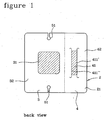
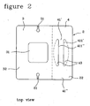
- the medical-use bandage 1 comprises a lower face designed to be turned to the skin, shown in Figure 1 , and an upper face on the opposite side, shown in Figure 2 .
- the bandage is designed to immobilize a tube 100 implanted in a body, the implanted tube 100 defining an exit site 101 from the body and a part 102 of the tube projecting from the body.
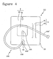
- the projecting part 102 of the tube is composed of a proximal portion 102', that is to say the portion of the tube which is nearest the body and which will be held in place by the first fixing means of the bandage, and a distal portion, that is to say the portion of the tube furthest from the body, a part of which will be held in place during non-treatment by the second fixing means of the bandage in a predetermined shape, preferably a loop.
- the bandage 1 comprises a base support 2 having a lower face 21 designed to be applied to the skin.
- This support may be for example a sheet of an impermeable material, the face applied to the skin consisting of a hypoallergenic material.
- the material may have good breatheability. All this allows the patient to tolerate the same bandage for several days.
- the bandage may be coated with a quantity of acrylic adhesive recognized for its high cutaneous tolerance.
- the material may be made impermeable to bacteria.
- This material may comprise a natural material such as cotton, woven or otherwise, applied to the lower face of an impermeable sheet, and/or may comprise a polyurethane material.
- the material may be elastic or rigid.
- the bandage will be white or flesh-coloured in particular.
- the bandage 1 essentially comprises two fixing means for fixing the tube of the catheter at two locations.
- the first fixing means 3 for fixing the exit site 101 have on the lower face 21 of the base support 2 an adhesive fixing part 32 designed to be stuck at least partly around the exit site 101 to the skin and to a proximal portion 102' of the projecting part 102 of the tube.
- the adhesive fixing part 32 (the unhatched area of the first means 3 in Figure 1 ) may partly or completely surround the exit site, may be in the shape of a ring on the base support, and may also be made adhesive as far as the edge of the base support. This part may be essentially square as shown in Figure 1 or rectangular or indeed round.
- first fixing means therefore make it possible to fix the proximal part of the tube of the catheter adhesively and permanently. This means that the proximal part of the tube is fixed adhesively and permanently throughout the period of usage and application of the bandage on the patient (some 2 to 3 days).
- the bandage 1 has second fixing means 4 for engaging the distal portion 102" of the projecting part 102 of the tube in a defined shape and in particular in a sliding manner.
- the second fixing means 4 may comprise:
- This band is an illustrative embodiment of means allowing the sliding passage of the tube which is to be fixed in position.
- the band will have all or part of its lower face nonadhesive.
- the band may be rectangular or square or be of some other shape.
- the second fixing means also comprise an adhesive attachment area 42 (the unhatched area) that is situated at least partly around the band 41, is defined on the lower face 21 of the support, and is designed to be stuck to the skin.
- This attachment area 42 allows the band to be fixed permanently to the skin.
- the adhesive attachment may surround the band completely or partially.
- the tube will be fixed to the second fixing means to form a loop during non-treatment time, and will be withdrawn from the second fixing means during treatment.
- the distal part of the tube can be moved (typically by sliding it) because of the second fixing means, the proximal part of the tube will remain adhesively fixed in position by the first fixing means.
- the fixing band of the second means may be attached by one or both of its sides by means of a fixed or removable attachment to the support, e.g. to facilitate the insertion of the tube through the second fixing means.
- the looped position of the tube is wanted during non-treatment time because it has been found by the applicant that this shape ensures that no tension is applied to the point where the catheter emerges due to the weight and length of the external line of the catheter.
- the external part of the catheter and the extender are thus held securely against the body of the patient and will not move during non-treatment time.
- the second fixing means will therefore be situated at a suitable distance from the first fixing means to allow a loop to be formed without too much risk of the tube being creased between the two fixing means.
- the distance between the two means depends on the dimension of each of the fixing means and/or on the length of external line to be attached.
- an example would be a rectangular bandage measuring approximately 10 cm by approximately 9 cm.
- the window of the first means (the nonadhesive part is transparent or semi-transparent in this example) would be roughly square with sides of approximately 4 cm.
- the band would be roughly a rectangle with a width of approximately 1 cm and a length of approximately 5 cm. The long sides of the rectangle would be parallel to one side of the square of the window and separated by approximately 2 cm.
- the band 41 may essentially be in the shape of a rectangle whose two long sides are the sides defining the two openings (411', 411").
- the two long sides have a length greater than the diameter of the tube, sufficient to allow the tube and the connector joining the catheter to the extender to be passed through (the dimension of the extender is greater than the diameter of the tube). This length may be at least twice as great as the dimension of the connector.
- the two short sides of the rectangle may have a length of for example at least twice the diameter of the tube.
- the band 41 can be formed in the base support 2: the two auxiliary sides (411', 411") forming the two openings are produced by two slits made through the thickness of the base support 2. If the band is rectangular, the two long sides of the band are the two slits. The tube will thus be able to be positioned (typically by sliding it) between the lower face of the band and the skin.
- the band 41 is a separate element from the base support 2 and is attached to the base support 2 by the opposite sides (41', 41 ") permanently or removably.
- the base support of the second fixing means 4 is a sheet and the band is a separate rectangular (for example) sheet attached to the support by two opposite sides. The tube can thus pass, typically by sliding, between the lower face of the band and that part of the upper face of the base support which is next to the band.
- each slit (411', 411 ") can be formed essentially into an arc of a circle tangent to the auxiliary opposite side and extending away from the band.
- the diameter of this arc of a circle is small compared with the length of the slit.
- the arc of a circle may be a semicircle. This form of arc of a circle allows the band to be lifted more easily and gives the band better resistance to movement of the tube. This reduces the risk of the end of an auxiliary opposite side tearing.
- the adhesive attachment area 42 of the second fixing means 4 can be in contact with the two auxiliary opposite sides (411', 411") of the band 41.
- the lower face of the part 42 of the second fixing means is adhesive at least on each side and in contact with the band 41, for example at least on the areas 43 of the part 42 that are hatched in Figure 1 . This allows the second means to keep the part 42 from moving and enables the tube to be inserted easily underneath the band 41 without the part 42 moving.
- the second fixing means 4 may comprise a thickened area 50 formed on the band 41 compared with the thickness of the base support 2, to enhance the strength of the band, which represents that area of the bandage which is subjected to the greatest tensile force.
- the thickened area 50 may extend only over the band 41.
- a sheet stuck to the lower face 21 of the base support may form the thickened area 50.
- the base support used for the second means is a film of generally constant thickness with one face entirely adhesive: it is easy to apply definitively the additional sheet which is intended to form the lower face of the band against the adhesive film.
- the thickened area 50 may also extend over the full width of the band 41.
- the thickened area 50 may extend over a major part of the length of the band and be situated approximately in the middle of the band, as shown in Figure 1 , to leave the ends of the auxiliary opposite sides with no thickened area.
- the thickened area preferably extends over approximately 80 to 95% of the band 41. This is to prevent tearing of the arcs of circles.
- the first fixing means 3 of the bandage may comprise, on the lower face of the base support, a protective part 31 designed to be placed over the exit site and surrounded by the adhesive fixing part 32.
- This protective part may be a film consisting of the base support which will be applied to the tube and the exit site to protect them against being knocked.
- this protective part may be a special sheet attached to the base support.
- These protective means may comprise a material designed to come into direct contact with the exit site and capable of absorbing any unwanted body fluid that oozes out of the patient's exit site and/or that is capable of forming a barrier to bacteria.
- the bandage here therefore has a dressing function on the exit site.
- the protective part 31 of the first fixing means 3 may be made of a transparent or semi-transparent material, meaning a material such that the exit site is left visible. In this way the condition of the exit site, which stays underneath the dressing for some 2 to 3 days, can be checked visually.
- the protective part 31 of the first fixing means 3 may be nonadhesive. This will allow the bandage to be withdrawn definitively without pulling on the part of the tube just in contact with the exit site and without subjecting the tube (which has been permanently implanted by surgery) to undesired pulling and/or withdrawal.
- the user will detach part of the adhesive part 32, place his finger on roughly the part of the tube coming out of the exit site, and detach the rest of the adhesive part 32 stuck to the tube, thus not pulling on the tube.
- At least one indentation 51 may be formed in an edge of the adhesive fixing part 32 of the first fixing means 3 of the bandage 1.
- the dimensions of the indentation are such that the projecting part 102 of the tube passing out of the adhesive fixing part 32 of the first fixing means 3 can be engaged in and held by the indentation 51.
- the outline of at least one indentation 51 is preferably in the shape of a mushroom so that the tube can be passed along the stalk of the mushroom and the head of the mushroom can accommodate the tube.
- the width of the stalk may be practically zero (a slit) or be approximately equal to the diameter of the tube.
- the outline of the indentation may be an arc of a circle (for example a semicircle) of diameter approximately equal to the diameter of the tube of the catheter or may be V-shaped or may be a combined shape of a slightly rounded V.
- the indentation may be any other shape envisaged by those skilled in the art capable of accommodating the tube on an edge of the first fixing means.
- At least one indentation may be situated on a straight line parallel to the band. This straight line is preferably in the mid-plane of the protective part (31).
- the dressing may have one indentation.
- the dressing may have two indentations, one on each of the two opposite sides of the first fixing means of the bandage ( Figure 1 ). This will allow the user to choose which of the 2 indentations to place the tube in.
- the bandage will be placed on the patient's abdomen in such a way that the first means are situated next to the second means (if the dressing is rectangular as shown in Figure 1 , then it will be arranged so as to extend horizontally across the abdomen).
- the catheter tube can be passed through either of the two indentations, as desired. It has been observed that the projecting proximal part of the tube emerging from the abdomen needs to be positioned vertically to achieve a better flow. It is for this reason that the indentations are positioned on the bandage in such a way as to keep the projecting proximal part of the tube vertical.
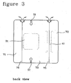
- the lower face of the base support may be entirely covered with a detachable film 70.
- This detachable film may contain silicone or any other material that can be stuck to one adhesive face and detached without harming the adhesive properties of the face.
- the detachable film 70 may be composed of one part or of at least two parts.
- the film is divided into at least a first film part 71 designed to at least partly cover the first fixing means 3 and a second film part 72 designed to at least partly cover the second fixing means 4.
- the detachable film may comprise a third film part 73 designed to cover both a part at least of the first fixing means 3 and a part at least of the second fixing means 4, as illustrated in Figures 3 and 5 . This will allow the first fixing means to be applied to the skin, followed by the second fixing means, after which the tube can be passed underneath the band.
- the first film part 71 is designed to cover a part of the first fixing means 3 that does not include the protective part 31
- the second film part 72 is designed to cover a part of the band as far as a line 75 passing between the auxiliary opposite sides (411', 411") of the band 41 of the second fixing means 4
- the third film part 73 intermediate between the first and second film parts (71, 72) is designed to cover the non-covered parts of the first and second fixing means not covered by the first and second film parts (71, 72).
- the base support of the bandage can be formed in one piece.
- the first fixing means will be roughly a square with sides equal to the width of the rectangle and the second fixing means will be the remaining rectangle, as shown in Figure 1 by the broken-line boundary.
- This boundary is purely abstract in the case of a one-piece support, but will be actual in the case of a support made in two pieces composed of the first and second fixing means. That is to say, the base support can be formed in a first part and a separate second part which define the first and second fixing means, respectively.
- the attachment area 42 of the second fixing means 4 may in one case consist simply of two parts on either side of the band 41 for fixing the band to the skin: the separate second means comprise the band 41, which would be fixed to the skin by at least two opposite adhesive attachment points.
- the part 43 of the upper face 22 of the support consists of the upper face of the first fixing means.
- the area of attachment 42 of the second fixing means 4 may consist of two parts on either side of the band 41 for fixing the band to the skin and may also consist of the areas 43 shown in Figure 2 on either side of the auxiliary opposite sides (411', 411 "). In this way the area of the second fixing means that adheres to the skin surrounds the band.
- the length and/or area of the adhesive attachment points will be decided with respect notably to the length of the nonadhesive base, to prevent either or both points peeling off at the wrong time.
- the user selects the optimum spacing between the first and second fixing means so that the loop of the tube can be of the optimum dimensions.
- the bandage in its packaging has been sterilized, for example with ethylene oxide.
- the bandage could be sterilized first and then enclosed in its packaging, or the reverse, or the bandage could be sterilized as it is being placed in the unclosed/unsealed packaging.
- the packaging may take the form of a peelable sachet consisting of two faces, e.g. one paper face and one transparent face.
- the bandage according to the invention may be envisaged with a medical-use tube fixed to it, the tube having an initial part fixed to the first fixing means, a free intermediate part that is essentially in the form of a loop, and a final part that is fixed in a sliding manner to the second fixing means over at least a part 43 of the upper face 22 of the support 2.
- the tube/bandage assembly can be applied to the skin of a patient who has an implanted tube, the projecting part of which is to be connected to the tube attached to the bandage.
- a process for applying the bandage according to the invention comprises the following steps:
- Step (1) may be preceded or followed directly by placing the tube in an indentation 51.
- step (3) the tube is inserted, e.g. slid, between the band and the skin directly, in the case of a band produced by two slits through the base support.
- the tube may be slid between the band and the support directly, in the case of a bandage made of a band added to the base support.
- step (3) will be total or partial detachment of the support band, positioning of the tube, and reattachment of the band to place the band over the tube.
- the order in which the steps have been written is preferably the order in which the process is carried out in time.
- the process for applying the bandage will include the following steps:
- the bandage comprises a nonadhesive detachable film 70 divided into a first film part 71 designed to cover a part of the first fixing means 3 which does not include the protective part 31, a second film part 72 designed to cover a part of the band as far as a line 75 passing between the auxiliary opposite sides (411', 411") of the band of the second fixing means 4, and a third film part 73 intermediate between the first and second film parts (71, 72) and designed to cover the non-covered parts of the first and second fixing means not covered by the first and second film parts (71, 72); then the process for applying the bandage includes the following steps:
Claims (19)
- Bandage (1) à usage médical ayant une face inférieure destinée à être orientée vers la peau, et une face supérieure du côté opposé ; ce bandage étant destiné à immobiliser un tube (100) implanté dans un corps, le tube (100) implanté définissant un site d'accès (101) dans le corps et une partie de tube saillante (102) du corps ; le bandage (1) comprenant :- un support de base (2) ayant une face inférieure (21) destinée à être appliquée sur la peau et une face supérieure (22),- des premiers moyens de fixation (3) comprenant sur la face inférieure (21) du support de base (2) une partie de fixation adhésive (32) destinée à être collée au moins partiellement autour du site d'accès (101) sur la peau et sur une portion proximale (102') de la partie saillante (102) du tube ; et- des seconds moyens de fixation (4) pour engager dans une forme déterminée et de façon coulissante la portion distale (102") de la partie saillante (102) du tube, les seconds moyens de fixation (4) comprenant :une bande (41) ayant une face inférieure non adhésive, cette bande comprenant :- deux côtés opposés (41', 41") reliés au support de base (2), et- deux côtés opposés auxiliaires (411', 411") définissant à travers la face supérieure du bandage (1) deux ouvertures pour permettre à la portion saillante distale (102") du tube de passer à travers les ouvertures ; et- une zone d'attache adhésive (42) qui est située au moins partiellement autour de la bande (41), est définie sur la face inférieure (21) du support et est destinée à être collée sur la peau.
- Bandage selon la revendication 1, où la bande (41) a sensiblement la forme d'un rectangle dont les deux côtés longs sont les côtés définissant les deux ouvertures (411', 411 ").
- Bandage selon la revendication 1 ou 2, où la bande (41) est formée dans le support de base (2) et où les deux côtés auxiliaires (411', 411 ") formant les deux ouvertures sont obtenus par deux fentes pratiquées dans l'épaisseur du support de base (2).
- Bandage selon la revendication 1 ou 2, où la bande (41) est un élément distinct du support de base (2) et est attachée au support de base (2) par les côtés opposés (41', 41").
- Bandage selon l'une des revendications 1 à 3, où l'extrémité de chaque côté opposé auxiliaire (411', 411 ") est formée sensiblement en forme d'arc de cercle tangent au côté opposé auxiliaire et s'étendant vers l'extérieur de la bande.
- Bandage selon l'une des revendications précédentes, où la zone d'attache adhésive (42) des seconds moyens de fixation (4) est en contact avec les deux côtés opposés auxiliaires (411', 411") de la bande (41).
- Bandage selon l'une des revendications précédentes, où les seconds moyens de fixation (4) comprennent une surépaisseur (50) sur la bande (41) par rapport à l'épaisseur du support de base (2), la surépaisseur (50) s'étendant de préférence uniquement sur la bande (41).
- Bandage selon la revendication précédente, comprenant une feuille collée sur la face inférieure (21) du support de base, la feuille constituant la surépaisseur (50).
- Bandage selon la revendication précédente en combinaison avec au moins l'une des revendications 3 et 5, où la surépaisseur (50) s'étend sur toute la largeur de la bande (41), la surépaisseur (50) s'étendant de préférence sur une majeure partie de la longueur de la bande.
- Bandage selon l'une des revendications précédentes, où les premiers moyens de fixation (3) comprennent, sur la face inférieure du support de base, une partie de protection (31) destinée à être placée sur le site d'accès et entourée par la partie de fixation adhésive (32), la partie de protection (31) des premiers moyens de fixation (3) étant de préférence non adhésive.
- Bandage selon l'une des revendications précédentes, où au moins une encoche (51) est formée dans un bord de la partie de fixation adhésive (32) des premiers moyens de fixation (3) du bandage (1), cette encoche étant dimensionnée de sorte que la partie saillante (102) du tube sortant de la partie de fixation adhésive (32) des premiers moyens de fixation puisse être engagée dans et maintenue par l'encoche (51), la découpe d'au moins une encoche (51) ayant de préférence la forme d'un champignon de sorte que le tube puisse être passé le long du pied du champignon et que la tête du champignon puisse recevoir le tube.
- Bandage selon l'une des deux revendications précédentes, où au moins une encoche est située sur une ligne droite parallèle à la bande, la ligne droite étant de préférence dans le plan médian de la partie de protection (31).
- Bandage selon l'une des revendications précédentes, où la face inférieure du support de base est entièrement recouverte d'un film amovible (70).
- Bandage selon la revendication précédente, où le film amovible (70) est non adhésif et est divisé en au moins :une première partie de film (71) destinée à recouvrir au moins partiellement les premiers moyens de fixation (3), etune seconde partie de film (72) destinée à recouvrir au moins partiellement les seconds moyens de fixation (4),le film amovible comprenant de préférence une troisième partie de film (73) destinée à recouvrir à la fois au moins une partie des premiers moyens de fixation (3) et au moins une partie des seconds moyens de fixation (4).
- Bandage selon la revendication précédente, où :la première partie de film (71) est destinée à recouvrir une partie des premiers moyens de fixation (3) qui ne comprend par la partie de protection (31),la seconde partie de film (72) est destinée à recouvrir une partie de la bande jusqu'à une ligne (75) passant entre les côtés opposés auxiliaires (411", 411") de la bande (41) des seconds moyens de fixation (4), etla troisième partie de film (73) intermédiaire aux première et seconde parties de film (71, 72) est destinée à recouvrir les parties non recouvertes des premiers et seconds moyens de fixation non recouvertes par les première et seconde parties de film (71, 72).
- Bandage selon l'une des revendications précédentes, où le support de base est formé d'une seule pièce.
- Bandage selon l'une des revendications 1 à 15, où le support de base est formé d'une première partie et d'une seconde partie qui définissent respectivement les premiers et seconds moyens de fixation.
- Bandage selon l'une des revendications précédentes, stérilisé et enfermé dans un emballage.
- Bandage selon l'une des revendications précédentes, auquel est fixé un tube à usage médical, le tube comprenant : une partie initiale fixée sur les premiers moyens de fixation, une partie intermédiaire libre qui a sensiblement la forme d'une boucle et une partie finale qui est fixée de façon coulissante aux seconds moyens de fixation sur au moins une partie (43) de la face supérieure (22) du support (2).
Applications Claiming Priority (2)
| Application Number | Priority Date | Filing Date | Title |
|---|---|---|---|
| FR0604221A FR2900817B1 (fr) | 2006-05-12 | 2006-05-12 | Bandage a usage medical pour un tube implante dans un patient, ainsi que le procede d'application de ce bandage sur la peau d'un patient |
| PCT/IB2006/002375 WO2007132288A1 (fr) | 2006-05-12 | 2006-08-30 | Bandage à usage médical |
Publications (2)
| Publication Number | Publication Date |
|---|---|
| EP2018206A1 EP2018206A1 (fr) | 2009-01-28 |
| EP2018206B1 true EP2018206B1 (fr) | 2014-10-08 |
Family
ID=37684054
Family Applications (1)
| Application Number | Title | Priority Date | Filing Date |
|---|---|---|---|
| EP06795378.6A Not-in-force EP2018206B1 (fr) | 2006-05-12 | 2006-08-30 | Bandage a usage medical |
Country Status (10)
| Country | Link |
|---|---|
| US (1) | US8663171B2 (fr) |
| EP (1) | EP2018206B1 (fr) |
| KR (1) | KR101188732B1 (fr) |
| CN (1) | CN101437566B (fr) |
| AU (1) | AU2006343774B2 (fr) |
| CA (1) | CA2651577C (fr) |
| DK (1) | DK2018206T3 (fr) |
| ES (1) | ES2523461T3 (fr) |
| FR (1) | FR2900817B1 (fr) |
| WO (1) | WO2007132288A1 (fr) |
Families Citing this family (30)
| Publication number | Priority date | Publication date | Assignee | Title |
|---|---|---|---|---|
| US20050182443A1 (en) | 2004-02-18 | 2005-08-18 | Closure Medical Corporation | Adhesive-containing wound closure device and method |
| US20060009099A1 (en) | 2004-07-12 | 2006-01-12 | Closure Medical Corporation | Adhesive-containing wound closure device and method |
| ITTO20060902A1 (it) * | 2006-12-19 | 2008-06-20 | Policare S R L | Dispositivo di fissaggio per cateteri o sonde medicali |
| US8349358B1 (en) * | 2010-04-15 | 2013-01-08 | Mcbride Emily Vann | Transdermal anesthetic applicator having thermochromic indication |
| EP3524288A3 (fr) | 2011-03-23 | 2019-11-20 | NxStage Medical Inc. | Systèmes de dialyse péritonéale |
| US9861733B2 (en) | 2012-03-23 | 2018-01-09 | Nxstage Medical Inc. | Peritoneal dialysis systems, devices, and methods |
| USD713048S1 (en) * | 2011-04-15 | 2014-09-09 | Lotte Co., Ltd. | Heat pad |
| US9149259B1 (en) * | 2011-08-21 | 2015-10-06 | Cynthia E. Allen | Patient safety and wellbeing device for covering wires and needles used in mammography or ultrasound guided needle localization |
| US9597425B2 (en) * | 2011-10-18 | 2017-03-21 | St. Teresa Medical, Inc. | Method of forming a hemostatic product |
| US20150086741A1 (en) * | 2012-04-23 | 2015-03-26 | 3M Innovative Properties Company | Conforming securement articles and methods of use |
| JP6030412B2 (ja) | 2012-10-23 | 2016-11-24 | エンゼルプレイングカード株式会社 | テーブルゲームシステム |
| US10456497B2 (en) | 2014-09-10 | 2019-10-29 | C. R. Bard, Inc. | Protective dressing for skin-placed medical device |
| USD824525S1 (en) | 2014-09-25 | 2018-07-31 | Ethicon Llc | Release paper for wound treament devices |
| CN105879194A (zh) * | 2014-11-20 | 2016-08-24 | 杨小林 | 固定用硬膜外腔导管组合贴 |
| EP3373853A4 (fr) | 2015-11-12 | 2019-07-10 | St. Teresa Medical, Inc. | Procédé de scellement d'une durotomie |
| USD773060S1 (en) | 2015-12-21 | 2016-11-29 | Covidien Lp | Sacral wound dressing |
| CN105920701A (zh) * | 2016-04-19 | 2016-09-07 | 苏州瑞华医院有限公司 | 一种静脉针固定贴膜 |
| US10835717B2 (en) * | 2016-06-27 | 2020-11-17 | Vlv Associates, Inc. | Dressing |
| US10792024B2 (en) | 2016-09-28 | 2020-10-06 | Ethicon, Inc. | Scaffolds with channels for joining layers of tissue at discrete points |
| USD848624S1 (en) | 2016-09-29 | 2019-05-14 | Ethicon, Inc. | Release paper for wound treatment devices |
| US10687986B2 (en) | 2016-09-29 | 2020-06-23 | Ethicon, Inc. | Methods and devices for skin closure |
| US10470934B2 (en) | 2016-09-29 | 2019-11-12 | Ethicon, Inc. | Methods and devices for skin closure |
| US10470935B2 (en) | 2017-03-23 | 2019-11-12 | Ethicon, Inc. | Skin closure systems and devices of improved flexibility and stretchability for bendable joints |
| US11504446B2 (en) | 2017-04-25 | 2022-11-22 | Ethicon, Inc. | Skin closure devices with self-forming exudate drainage channels |
| CN107310955B (zh) * | 2017-07-07 | 2018-05-08 | 青岛大学附属医院 | 一种医疗绷带设备 |
| WO2019089717A1 (fr) | 2017-11-02 | 2019-05-09 | St. Teresa Medical, Inc. | Produits de scellement à base de fibrine |
| US20190151525A1 (en) * | 2017-11-22 | 2019-05-23 | Norris Alaiasa | Device to secure a catheter port |
| SE541821C2 (en) * | 2017-11-27 | 2019-12-27 | Clinical Laserthermia Systems Ab | Surgical probe positioning device |
| US11872337B2 (en) | 2018-02-28 | 2024-01-16 | Nxstage Medical, Inc. | Fluid preparation and treatment devices methods and systems |
| US10993708B2 (en) | 2018-07-31 | 2021-05-04 | Ethicon, Inc. | Skin closure devices with interrupted closure |
Family Cites Families (136)
| Publication number | Priority date | Publication date | Assignee | Title |
|---|---|---|---|---|
| US1570181A (en) | 1923-01-16 | 1926-01-19 | John B Owens | Boring machine |
| US1601735A (en) | 1925-02-27 | 1926-10-05 | Flintkote Co | Roofing shingle |
| FR1288390A (fr) | 1960-04-18 | 1962-03-24 | Minnesota Mining & Mfg | Rubans adhésifs perméables à l'air |
| US3018881A (en) | 1960-06-02 | 1962-01-30 | Minnesota Mining & Mfg | Adhesive bandage package unit |
| FR1314185A (fr) | 1962-01-24 | 1963-01-04 | Minnesota Mining & Mfg | Pansement adhésif individuel |
| US3285245A (en) | 1964-07-06 | 1966-11-15 | Minnesota Mining & Mfg | Absorbent wound dressing |
| NO134790C (no) | 1968-07-09 | 1984-03-22 | Smith & Nephew | Klebende,; trykkfoelsomt, vanndamp-permeabelt produkt for bruk paa hud hos mennesker. |
| US3765421A (en) | 1972-03-10 | 1973-10-16 | J Poprik | Holders for surgical tubes |
| GB1445092A (en) | 1972-08-16 | 1976-08-04 | Eakin T G | Surgical drainage appliance |
| US4239041A (en) | 1977-03-03 | 1980-12-16 | Moncrief Jack W | Method for continuous ambulatory peritoneal dialysis |
| US4112177A (en) | 1978-01-23 | 1978-09-05 | Minnesota Mining And Manufacturing Company | Porous adhesive tape |
| US4346700A (en) | 1979-11-16 | 1982-08-31 | Minnesota Mining & Manufacturing Company | Pressure-sensitive adhesive sheet material |
| ATE23801T1 (de) | 1981-02-09 | 1986-12-15 | Smith & Nephew Ass | Verbaende. |
| GB2094154B (en) | 1981-03-06 | 1985-08-21 | Eakin Thomas George | Surgical drainage or wound dressing appliance |
| US4366814A (en) | 1981-04-06 | 1983-01-04 | Minnesota Mining And Manufacturing Company | Elastic bandage material |
| IE54942B1 (en) | 1982-05-06 | 1990-03-28 | Smith & Nephew Ass | Bandages, components thereof and use |
| DE3464326D1 (en) | 1983-04-06 | 1987-07-30 | Smith & Nephew Ass | Dressing |
| GB8322200D0 (en) | 1983-08-18 | 1983-09-21 | Smith & Nephew Ass | Bandages |
| GB8334484D0 (en) | 1983-12-24 | 1984-02-01 | Smith & Nephew Ass | Surgical dressing |
| EP0168174A1 (fr) | 1984-06-13 | 1986-01-15 | Smith & Nephew Inc. | Pansement sous forme de film |
| US4582508A (en) | 1984-09-27 | 1986-04-15 | Pavelka Wilma F | Garment for receiving catheters and the like |
| US4578062A (en) | 1984-12-14 | 1986-03-25 | Schneider Paul E | Intravenous catheter holder |
| AU557862B3 (en) | 1985-05-10 | 1987-01-13 | Minnesota Mining And Manufacturing Company | Medical tape pad |
| US4662873A (en) * | 1985-09-03 | 1987-05-05 | M.D. Engineering | Intravenous tube stress relief bracelet |
| US4667661A (en) | 1985-10-04 | 1987-05-26 | Minnesota Mining And Manufacturing Company | Curable resin coated sheet having reduced tack |
| US4967740A (en) | 1986-06-11 | 1990-11-06 | Minnesota Mining And Manufacturing Company | Dispensable tapes |
| ZA873791B (en) | 1986-06-11 | 1989-01-25 | Minnesota Mining & Mfg | Dispensable tapes |
| US4944040A (en) | 1986-06-26 | 1990-07-31 | Minnesota Mining And Manufacturing Company | Light occlusive eye patch |
| GB8617790D0 (en) | 1986-07-21 | 1986-08-28 | Smith & Nephew Ass | Wound dressing |
| US4743232A (en) | 1986-10-06 | 1988-05-10 | The Clinipad Corporation | Package assembly for plastic film bandage |
| FR2610310B1 (fr) | 1987-02-02 | 1989-05-26 | Plasto Sa | Devidoir pour ruban adhesif |
| FR2610909B1 (fr) | 1987-02-13 | 1989-06-23 | Plasto Sa | Dispositif de distribution d'articles adhesifs |
| GB8706116D0 (en) | 1987-03-14 | 1987-04-15 | Smith & Nephew Ass | Adhesive dressings |
| GB8726777D0 (en) | 1987-11-16 | 1987-12-23 | Smith & Nephew Ass | Adhesive dressings |
| DE8800086U1 (fr) | 1988-01-07 | 1988-03-03 | Fa. Michael Patzelt, 5014 Kerpen, De | |
| GB8801636D0 (en) | 1988-01-23 | 1988-02-24 | Smith & Nephew Ass | Bandages |
| US4837062A (en) | 1988-02-08 | 1989-06-06 | Minnesota Mining And Manufacturing Company | Pressure-sensitive adhesive coated sheets and tape pad with easily separable tabs |
| US5230701A (en) | 1988-05-13 | 1993-07-27 | Minnesota Mining And Manufacturing Company | Elastomeric adhesive and cohesive materials |
| AU609963B2 (en) | 1988-05-13 | 1991-05-09 | Minnesota Mining And Manufacturing Company | Elastomeric adhesive and cohesive materials |
| GB8812096D0 (en) * | 1988-05-21 | 1988-06-22 | Smith & Nephew Ass | Adhesive sheet |
| EP0343807A3 (fr) | 1988-05-27 | 1991-01-02 | SMITH & NEPHEW UNITED, INC. | Pansement adhésif absorbant à hydratation contrôlée |
| CA1334640C (fr) | 1988-09-09 | 1995-03-07 | Smith And Nephew Plc | Bandage ajustable |
| US5048122A (en) | 1989-01-13 | 1991-09-17 | Prieur Deborah G | Garment for shielding lines connected to a patient |
| DE69012801T2 (de) | 1989-02-25 | 1995-03-23 | Smith & Nephew | Gestrickte oder gewirkte elastische bandage. |
| US4955867A (en) | 1989-05-12 | 1990-09-11 | Endo Walter Y | Peritoneal dialysis catheter protector belt |
| US5270358A (en) | 1989-12-28 | 1993-12-14 | Minnesota Mining And Manufacturing Company | Composite of a disperesed gel in an adhesive matrix |
| FR2664609B1 (fr) | 1990-07-13 | 1994-08-05 | Plasto Sa | Ruban adhesif double face de securite. |
| US5160315A (en) | 1991-04-05 | 1992-11-03 | Minnesota Mining And Manufacturing Company | Combined adhesive strip and transparent dressing delivery system |
| US5230350A (en) | 1991-05-29 | 1993-07-27 | Tabex Industries, Inc. | Moisture barrier for indwelling catheters and the like |
| US5406267A (en) | 1991-07-22 | 1995-04-11 | Curtis; Stephen J. | Method and apparatus for the monitoring of the operation of linear and rotary encoders |
| DK193991D0 (da) * | 1991-11-29 | 1991-11-29 | Nicomed Aps | A bandage for fixating a cannula of a venous catheter relative to a skin surface part of a person |
| GB9210036D0 (en) | 1992-05-09 | 1992-06-24 | Smith & Nephew | Crepe effect bandages |
| US5939339A (en) | 1992-07-22 | 1999-08-17 | 3M Innovative Properties Company | Absorbent self adhering elastic bandage |
| GB9303200D0 (en) | 1993-02-17 | 1993-03-31 | Smith & Nephew | Orthopaedic casting bandage |
| GB9307312D0 (en) | 1993-04-07 | 1993-06-02 | United Surgical Services Ltd | Surgical wound dressings |
| US5716661A (en) | 1993-04-16 | 1998-02-10 | Minnesota Mining And Manufacturing Company | Method of making a light weight orthopedic casting tape |
| US5425719A (en) | 1993-05-27 | 1995-06-20 | Lessing, Jr.; Kennith C. | Peritoneal dialysis catheter belt pack |
| US5344415A (en) | 1993-06-15 | 1994-09-06 | Deroyal Industries, Inc. | Sterile system for dressing vascular access site |
| US5385534A (en) | 1993-07-09 | 1995-01-31 | Smith & Nephew Donjoy Inc. | Splint assembled from a flat stackable kit |
| US5718674A (en) | 1993-11-04 | 1998-02-17 | Smith & Nephew Plc | Bandages |
| GB9323161D0 (en) | 1993-11-10 | 1994-01-05 | Smith & Nephew | Crepe effect bandage |
| GB9401683D0 (en) | 1994-01-28 | 1994-03-23 | Smith & Nephew | Catheter/cannula dressing |
| SE9400832D0 (sv) | 1994-03-10 | 1994-03-10 | Gambro Ab | Kateterskydd |
| FR2721323B1 (fr) | 1994-06-15 | 1997-06-06 | Plasto Sa | Bande adhésive double face asymétrique. |
| US5468229A (en) | 1994-11-02 | 1995-11-21 | Chandler; Janice | Peritoneal dialysis catheter support belt |
| GB2295766B (en) | 1994-12-09 | 1998-07-01 | Bernard Keith Clements | Apparatus for carrying a container about the person |
| US5496282A (en) | 1994-12-12 | 1996-03-05 | Militzer; George G. | Apparatus and method to stabilize a peritoneal dialysis catheter |
| US5776106A (en) | 1995-01-03 | 1998-07-07 | Matyas; Melanie E. | Replaceable flexible protective cover for an infusion device |
| US5885254A (en) * | 1995-01-03 | 1999-03-23 | Matyas; Melanie E. | Replaceable flexible protective cover for an infusion device |
| US5840052A (en) | 1995-01-27 | 1998-11-24 | Bertek, Inc. | Adhesive dressing applicator |
| WO1996026251A1 (fr) | 1995-02-21 | 1996-08-29 | Minnesota Mining And Manufacturing Company | Article adhesif en feuille |
| US6004253A (en) | 1995-05-17 | 1999-12-21 | 3M Innovative Properties Company | Medical adhesive bandage manufacturing |
| US5707348A (en) | 1995-06-06 | 1998-01-13 | Krogh; Steve S. | Intravenous bandage |
| ES2153121T3 (es) | 1995-08-11 | 2001-02-16 | Smith & Nephew | Adhesivos. |
| US5669884A (en) | 1995-09-11 | 1997-09-23 | Bennes; Solita M. | Tuck-away belt for peritoneal dialysis patients |
| WO1997021459A1 (fr) * | 1995-12-13 | 1997-06-19 | Nikomed Aps | Dispositif pour fixer un drain |
| FR2743814B1 (fr) | 1996-01-19 | 1998-03-27 | Plasto Sa | Pate adhesive sensible a la pression |
| DE19603532C2 (de) | 1996-02-01 | 1998-05-07 | Elisabeth Emberger | Peritonealkatheter-Suspensorium als Kleidungsstück |
| FR2746105A1 (fr) | 1996-03-15 | 1997-09-19 | Plasto Sa | Film de masquage adhesif a deux lisieres adhesives differenciees |
| US5688248A (en) | 1996-05-02 | 1997-11-18 | Lessing, Jr.; Kennith C. | Adult and pediatric peritoneal dialysis catheter belt pack |
| FR2748661B1 (fr) | 1996-05-15 | 1998-11-20 | Vogel Denise | Pansement protecteur pour catheters profonds et son necessaire hygienique |
| FR2751338B1 (fr) | 1996-07-17 | 1998-09-04 | Plasto Sa | Adhesif double face demontable |
| ES2227687T3 (es) | 1996-10-04 | 2005-04-01 | Unomedical A/S | Dispositivo de fijacion para fijar un cateter unido a una parte de la superficie de la piel de una persona. |
| US6018092A (en) | 1997-03-04 | 2000-01-25 | 3M Innovative Properties Company | Medical adhesive bandage, delivery system and method |
| FR2762353B1 (fr) | 1997-04-17 | 1999-06-18 | Plasto Sa | Joint d'angle auto-adhesif pour feuillures |
| DE29708126U1 (de) | 1997-04-30 | 1997-07-24 | Auhagen Peter | Zentralvenöser Katheterschnellverband |
| CA2289730A1 (fr) | 1997-05-10 | 1998-11-19 | Tim Jones | Dispositifs indicateurs d'extension |
| US6432074B1 (en) | 1997-05-10 | 2002-08-13 | Smith & Nephew Plc | Extension indicators |
| FR2764502B1 (fr) | 1997-06-11 | 1999-08-06 | Plasto Sa | Champ operatoire modulable |
| US5968011A (en) | 1997-06-20 | 1999-10-19 | Maersk Medical A/S | Subcutaneous injection set |
| US20030066122A1 (en) | 1997-07-08 | 2003-04-10 | Niedermeyer William P | Disposable front opening brief with pre-selected pad shape and location |
| GB9718923D0 (en) | 1997-09-05 | 1997-11-12 | T G Eakin Limited | Wound dressing |
| FR2759379A1 (fr) | 1997-10-06 | 1998-08-14 | Urgo Laboratoires | Nouvelle masse adhesive hydrophile |
| FR2770221B1 (fr) | 1997-10-24 | 1999-12-31 | Plasto Sa | Composite adhesif imprimable |
| US6126639A (en) | 1998-02-05 | 2000-10-03 | Sutherland; Joanne M. | Continuous ambulatory peritoneal dialysis catheter support undergarment |
| US6736797B1 (en) | 1998-06-19 | 2004-05-18 | Unomedical A/S | Subcutaneous infusion set |
| FR2780980B1 (fr) | 1998-07-07 | 2000-09-15 | Plasto Sa | Composition pour le traitement de surfaces a adhesiver et procede mettant en oeuvre cette composition |
| US6355021B1 (en) | 1998-07-14 | 2002-03-12 | Maersk Medical A/S | Medical puncturing device |
| FR2783412B1 (fr) | 1998-09-18 | 2000-12-15 | Lhd Lab Hygiene Dietetique | Compresse non adherente sterile |
| DK173976B1 (da) | 1998-09-25 | 2002-03-18 | Maersk Medical As | Apparat til måling af strømningen af en væske, specielt urin, fra en patient |
| FR2785526B1 (fr) | 1998-11-06 | 2001-03-30 | Plasto Sa | Dispositif de securite pour colostomie |
| FR2786434B1 (fr) | 1998-11-26 | 2001-11-02 | Plasto Sa | Dispositif adhesif pour la decoration |
| FR2790763B1 (fr) | 1999-03-09 | 2001-06-01 | Lhd Lab Hygiene Dietetique | Nouvelle masse adhesive hydrocolloide presentant une meilleure resistance a la degradation de sa capacite d'absorption apres radiosterilisation |
| US6436074B1 (en) | 1999-06-08 | 2002-08-20 | Jarrel Eugene Lee | Garment for securing and exposing a peritoneal dialysis catheter and catheter exit site |
| FR2796769B1 (fr) | 1999-07-23 | 2001-08-24 | Plasto Sa | Gaine fixable pour faisceau de fils |
| FR2802938B1 (fr) | 1999-12-22 | 2006-05-19 | Plasto Sa | Feuille de mousse adhesive enroulable sans protecteur |
| FR2805275B1 (fr) | 2000-02-21 | 2004-12-10 | Plasto Sa | Procede de fixation de protheses externes |
| FR2807055B1 (fr) | 2000-04-03 | 2002-06-28 | Plasto Sa | Bande adhesive de protection et d'insonorisation |
| DK1272244T3 (da) | 2000-04-06 | 2004-09-20 | Unomedical As | Et koblingsarrangement |
| DK174620B1 (da) | 2000-04-06 | 2003-07-28 | Maersk Medical As | En ventilanordning |
| US6206854B1 (en) | 2000-05-08 | 2001-03-27 | Kathleen M. Weaver | Catheter garment |
| US6544232B1 (en) | 2000-07-18 | 2003-04-08 | Mcdaniel Gladys P. | Cystostomy catheter belt |
| US6267115B1 (en) * | 2000-09-25 | 2001-07-31 | Florine Marshel | Intravenous protecting device |
| US6706940B2 (en) | 2001-02-22 | 2004-03-16 | George Medical, L.L.C. | Transparent film dressing and a method for applying and making the same |
| US6960179B2 (en) | 2001-11-16 | 2005-11-01 | National Quality Care, Inc | Wearable continuous renal replacement therapy device |
| FR2832723B1 (fr) | 2001-11-28 | 2004-02-20 | Plasto Sa | Bande ou feuille adhesive, article a trois dimensions et rouleau obtenus a l'aide d'une telle bande et faisceau d'elements conducteurs allonges gaine a l'aide d'une telle bande |
| FR2842469B1 (fr) | 2002-07-17 | 2004-10-15 | Plasto Sa | Feuille de protection autoadhesive pour carrosserie de vehicules automobiles |
| FR2843120B1 (fr) | 2002-07-31 | 2004-10-22 | Plasto Sa | Element complexe adhesif et son utilisation pour la fabrication d'un panneau d'etancheite et/ou d'insonorisation dans des vehicules automobiles |
| US20040051019A1 (en) | 2002-09-02 | 2004-03-18 | Mogensen Lasse Wesseltoft | Apparatus for and a method of adjusting the length of an infusion tube |
| ATE419033T1 (de) | 2002-09-02 | 2009-01-15 | Unomedical As | Gerät zur subkutanen verabreichung von medikamenten an einem patienten und zugehöriges rohr |
| DE60325624D1 (de) | 2002-09-02 | 2009-02-12 | Unomedical As | Vorrichtung zur subkutanen verabreichung eines medikaments an einen patienten |
| AU2003257754A1 (en) | 2002-09-02 | 2004-03-19 | Unomedical A/S | An apparatus and a method for adjustment of the length of an infusion tubing |
| DK1421968T3 (da) | 2002-11-19 | 2010-03-01 | Pajunk Gmbh & Co Kg Besitzverwaltung | Indretning til fiksering af et kateter og et filter |
| US20040204685A1 (en) * | 2003-02-06 | 2004-10-14 | Medical Device Group, Inc. | Flexible IV site protector and method of using same |
| DK1592469T3 (da) | 2003-02-12 | 2009-03-30 | Unomedical As | Afdækning til infusionssted |
| ATE346646T1 (de) | 2003-02-12 | 2006-12-15 | Unomedical As | Medizinischer konnektor und verfahren zum spritzgiessen eines solchen konnektors |
| DK174883B1 (da) | 2003-02-27 | 2004-01-19 | Unomedical As | Engangsurinpose til opsamling af urin |
| PL1608420T3 (pl) | 2003-04-01 | 2007-01-31 | Unomedical As | Urządzenie infuzyjne i arkusz materiału przylepnego oraz zdzieralna nakładka |
| ATE390105T1 (de) | 2003-05-14 | 2008-04-15 | Unomedical As | Beutel zur flüssigkeitsaufnahme |
| US20050020995A1 (en) | 2003-07-22 | 2005-01-27 | Sheila Shaw | Peritoneal dialysis security band and methods of use |
| FR2860437A1 (fr) | 2003-10-02 | 2005-04-08 | Emmanuel Berque | Support de drain auto decollable |
| DE20316109U1 (de) | 2003-10-21 | 2004-02-19 | Lohrer, Heinz, Dr.med. | Bandagen-Einlagen/Passteil-Verbund |
| DK1682326T3 (da) | 2003-11-14 | 2008-12-01 | Unomedical As | Injektionsstöbning af et kateter |
| US7294751B2 (en) * | 2005-08-23 | 2007-11-13 | Tri-State Hospital Supply Corporation | Window dressing |
| US7723561B2 (en) * | 2005-09-09 | 2010-05-25 | Centurion Medical Products Corporation | PIV dressing assembly |
| US9526868B2 (en) * | 2005-10-24 | 2016-12-27 | Tionne Allen Bennett | Intravenous catheter protective cover |
-
2006
- 2006-05-12 FR FR0604221A patent/FR2900817B1/fr not_active Expired - Fee Related
- 2006-08-30 AU AU2006343774A patent/AU2006343774B2/en not_active Ceased
- 2006-08-30 CA CA2651577A patent/CA2651577C/fr not_active Expired - Fee Related
- 2006-08-30 DK DK06795378.6T patent/DK2018206T3/da active
- 2006-08-30 KR KR1020087030263A patent/KR101188732B1/ko not_active IP Right Cessation
- 2006-08-30 ES ES06795378.6T patent/ES2523461T3/es active Active
- 2006-08-30 US US12/300,410 patent/US8663171B2/en not_active Expired - Fee Related
- 2006-08-30 EP EP06795378.6A patent/EP2018206B1/fr not_active Not-in-force
- 2006-08-30 WO PCT/IB2006/002375 patent/WO2007132288A1/fr active Application Filing
- 2006-08-30 CN CN2006800545717A patent/CN101437566B/zh not_active Expired - Fee Related
Also Published As
| Publication number | Publication date |
|---|---|
| US20100016802A1 (en) | 2010-01-21 |
| CA2651577A1 (fr) | 2007-11-22 |
| WO2007132288A1 (fr) | 2007-11-22 |
| AU2006343774B2 (en) | 2012-02-16 |
| FR2900817A1 (fr) | 2007-11-16 |
| KR101188732B1 (ko) | 2012-10-10 |
| CN101437566A (zh) | 2009-05-20 |
| ES2523461T3 (es) | 2014-11-26 |
| US8663171B2 (en) | 2014-03-04 |
| CN101437566B (zh) | 2012-10-17 |
| FR2900817B1 (fr) | 2008-12-19 |
| CA2651577C (fr) | 2012-04-24 |
| DK2018206T3 (da) | 2014-10-27 |
| AU2006343774A1 (en) | 2007-11-22 |
| KR20090006229A (ko) | 2009-01-14 |
| EP2018206A1 (fr) | 2009-01-28 |
Similar Documents
| Publication | Publication Date | Title |
|---|---|---|
| EP2018206B1 (fr) | Bandage a usage medical | |
| US5271745A (en) | Medical tubing retaining device and method of use | |
| US5496282A (en) | Apparatus and method to stabilize a peritoneal dialysis catheter | |
| RU2661779C2 (ru) | Система крепления медицинских приспособлений | |
| US6809230B2 (en) | Waterproof venipuncture site cover | |
| JP3152398B2 (ja) | 流体接続装置及び方法 | |
| EP2882391B1 (fr) | Dispositif de pansement intégré | |
| US6222090B1 (en) | Waterproof injection port cover | |
| US20160317785A1 (en) | Intravenous splint cover and associated methods | |
| EP3810248A1 (fr) | Systèmes et méthodes de sécurisation de cathéters | |
| US20140046263A1 (en) | Protective shower guard for indwelling medical catheters | |
| US20220401700A1 (en) | Device for securing a catheter | |
| CN211327269U (zh) | 一种颈内静脉留置透析导管安全固定装置 | |
| EP2982355B1 (fr) | Pansement auto-adhésif | |
| JP4335325B2 (ja) | カテーテル固定装置 | |
| US20080167626A1 (en) | Catheter covering for use in bathing | |
| WO2015116571A1 (fr) | Dispositif de fixation pour conduits médicaux | |
| CN209916906U (zh) | 一种植入式静脉输液港的护理套件 | |
| US20220355079A1 (en) | A sanitary dressing | |
| CN213249465U (zh) | 透析导管专用止血带 | |
| EP3378451A1 (fr) | Pansement sanitaire | |
| JP2006341114A (ja) | カテーテル固定装置 | |
| CN211096665U (zh) | 静脉留置针弹力固定保护套 | |
| JP2002320670A (ja) | 腹膜透析用保護具 | |
| JP2004351019A (ja) | 留置針挿入用ホール形成ピン保護部材 |
Legal Events
| Date | Code | Title | Description |
|---|---|---|---|
| PUAI | Public reference made under article 153(3) epc to a published international application that has entered the european phase |
Free format text: ORIGINAL CODE: 0009012 |
|
| 17P | Request for examination filed |
Effective date: 20081104 |
|
| AK | Designated contracting states |
Kind code of ref document: A1 Designated state(s): AT BE BG CH CY CZ DE DK EE ES FI FR GB GR HU IE IS IT LI LT LU LV MC NL PL PT RO SE SI SK TR |
|
| AX | Request for extension of the european patent |
Extension state: AL BA HR MK RS |
|
| 111Z | Information provided on other rights and legal means of execution |
Free format text: AT BE BG CH CY CZ DE DK EE ES FI FR GB GR HU IE IS IT LT LU LV MC NL PL PT RO SE SI SK TR Effective date: 20090504 |
|
| RAP1 | Party data changed (applicant data changed or rights of an application transferred) |
Owner name: FRESENIUS MEDICAL CARE DEUTSCHLAND GMBH |
|
| 111Z | Information provided on other rights and legal means of execution |
Free format text: AT BE BG CH CY CZ DE DK EE ES FI FR GB GR HU IE IS IT LT LU LV MC NL PL PT RO SE SI SK TR Effective date: 20081020 |
|
| DAX | Request for extension of the european patent (deleted) | ||
| 17Q | First examination report despatched |
Effective date: 20140319 |
|
| GRAP | Despatch of communication of intention to grant a patent |
Free format text: ORIGINAL CODE: EPIDOSNIGR1 |
|
| INTG | Intention to grant announced |
Effective date: 20140626 |
|
| GRAS | Grant fee paid |
Free format text: ORIGINAL CODE: EPIDOSNIGR3 |
|
| GRAA | (expected) grant |
Free format text: ORIGINAL CODE: 0009210 |
|
| AK | Designated contracting states |
Kind code of ref document: B1 Designated state(s): AT BE BG CH CY CZ DE DK EE ES FI FR GB GR HU IE IS IT LI LT LU LV MC NL PL PT RO SE SI SK TR |
|
| REG | Reference to a national code |
Ref country code: GB Ref legal event code: FG4D |
|
| REG | Reference to a national code |
Ref country code: AT Ref legal event code: REF Ref document number: 690271 Country of ref document: AT Kind code of ref document: T Effective date: 20141015 Ref country code: CH Ref legal event code: EP |
|
| REG | Reference to a national code |
Ref country code: DK Ref legal event code: T3 Effective date: 20141024 |
|
| REG | Reference to a national code |
Ref country code: IE Ref legal event code: FG4D |
|
| REG | Reference to a national code |
Ref country code: DE Ref legal event code: R096 Ref document number: 602006043301 Country of ref document: DE Effective date: 20141120 |
|
| REG | Reference to a national code |
Ref country code: ES Ref legal event code: FG2A Ref document number: 2523461 Country of ref document: ES Kind code of ref document: T3 Effective date: 20141126 |
|
| REG | Reference to a national code |
Ref country code: SE Ref legal event code: TRGR |
|
| REG | Reference to a national code |
Ref country code: NL Ref legal event code: VDEP Effective date: 20141008 |
|
| REG | Reference to a national code |
Ref country code: AT Ref legal event code: MK05 Ref document number: 690271 Country of ref document: AT Kind code of ref document: T Effective date: 20141008 |
|
| REG | Reference to a national code |
Ref country code: LT Ref legal event code: MG4D |
|
| PG25 | Lapsed in a contracting state [announced via postgrant information from national office to epo] |
Ref country code: NL Free format text: LAPSE BECAUSE OF FAILURE TO SUBMIT A TRANSLATION OF THE DESCRIPTION OR TO PAY THE FEE WITHIN THE PRESCRIBED TIME-LIMIT Effective date: 20141008 |
|
| PG25 | Lapsed in a contracting state [announced via postgrant information from national office to epo] |
Ref country code: PT Free format text: LAPSE BECAUSE OF FAILURE TO SUBMIT A TRANSLATION OF THE DESCRIPTION OR TO PAY THE FEE WITHIN THE PRESCRIBED TIME-LIMIT Effective date: 20150209 Ref country code: LT Free format text: LAPSE BECAUSE OF FAILURE TO SUBMIT A TRANSLATION OF THE DESCRIPTION OR TO PAY THE FEE WITHIN THE PRESCRIBED TIME-LIMIT Effective date: 20141008 Ref country code: IS Free format text: LAPSE BECAUSE OF FAILURE TO SUBMIT A TRANSLATION OF THE DESCRIPTION OR TO PAY THE FEE WITHIN THE PRESCRIBED TIME-LIMIT Effective date: 20150208 |
|
| PG25 | Lapsed in a contracting state [announced via postgrant information from national office to epo] |
Ref country code: CY Free format text: LAPSE BECAUSE OF FAILURE TO SUBMIT A TRANSLATION OF THE DESCRIPTION OR TO PAY THE FEE WITHIN THE PRESCRIBED TIME-LIMIT Effective date: 20141008 Ref country code: LV Free format text: LAPSE BECAUSE OF FAILURE TO SUBMIT A TRANSLATION OF THE DESCRIPTION OR TO PAY THE FEE WITHIN THE PRESCRIBED TIME-LIMIT Effective date: 20141008 Ref country code: GR Free format text: LAPSE BECAUSE OF FAILURE TO SUBMIT A TRANSLATION OF THE DESCRIPTION OR TO PAY THE FEE WITHIN THE PRESCRIBED TIME-LIMIT Effective date: 20150109 Ref country code: PL Free format text: LAPSE BECAUSE OF FAILURE TO SUBMIT A TRANSLATION OF THE DESCRIPTION OR TO PAY THE FEE WITHIN THE PRESCRIBED TIME-LIMIT Effective date: 20141008 Ref country code: AT Free format text: LAPSE BECAUSE OF FAILURE TO SUBMIT A TRANSLATION OF THE DESCRIPTION OR TO PAY THE FEE WITHIN THE PRESCRIBED TIME-LIMIT Effective date: 20141008 |
|
| REG | Reference to a national code |
Ref country code: DE Ref legal event code: R097 Ref document number: 602006043301 Country of ref document: DE |
|
| PG25 | Lapsed in a contracting state [announced via postgrant information from national office to epo] |
Ref country code: SK Free format text: LAPSE BECAUSE OF FAILURE TO SUBMIT A TRANSLATION OF THE DESCRIPTION OR TO PAY THE FEE WITHIN THE PRESCRIBED TIME-LIMIT Effective date: 20141008 Ref country code: CZ Free format text: LAPSE BECAUSE OF FAILURE TO SUBMIT A TRANSLATION OF THE DESCRIPTION OR TO PAY THE FEE WITHIN THE PRESCRIBED TIME-LIMIT Effective date: 20141008 Ref country code: EE Free format text: LAPSE BECAUSE OF FAILURE TO SUBMIT A TRANSLATION OF THE DESCRIPTION OR TO PAY THE FEE WITHIN THE PRESCRIBED TIME-LIMIT Effective date: 20141008 Ref country code: RO Free format text: LAPSE BECAUSE OF FAILURE TO SUBMIT A TRANSLATION OF THE DESCRIPTION OR TO PAY THE FEE WITHIN THE PRESCRIBED TIME-LIMIT Effective date: 20141008 |
|
| PLBE | No opposition filed within time limit |
Free format text: ORIGINAL CODE: 0009261 |
|
| STAA | Information on the status of an ep patent application or granted ep patent |
Free format text: STATUS: NO OPPOSITION FILED WITHIN TIME LIMIT |
|
| 26N | No opposition filed |
Effective date: 20150709 |
|
| PG25 | Lapsed in a contracting state [announced via postgrant information from national office to epo] |
Ref country code: SI Free format text: LAPSE BECAUSE OF FAILURE TO SUBMIT A TRANSLATION OF THE DESCRIPTION OR TO PAY THE FEE WITHIN THE PRESCRIBED TIME-LIMIT Effective date: 20141008 |
|
| PG25 | Lapsed in a contracting state [announced via postgrant information from national office to epo] |
Ref country code: LU Free format text: LAPSE BECAUSE OF FAILURE TO SUBMIT A TRANSLATION OF THE DESCRIPTION OR TO PAY THE FEE WITHIN THE PRESCRIBED TIME-LIMIT Effective date: 20150830 Ref country code: MC Free format text: LAPSE BECAUSE OF FAILURE TO SUBMIT A TRANSLATION OF THE DESCRIPTION OR TO PAY THE FEE WITHIN THE PRESCRIBED TIME-LIMIT Effective date: 20141008 |
|
| REG | Reference to a national code |
Ref country code: CH Ref legal event code: PL |
|
| PG25 | Lapsed in a contracting state [announced via postgrant information from national office to epo] |
Ref country code: LI Free format text: LAPSE BECAUSE OF NON-PAYMENT OF DUE FEES Effective date: 20150831 Ref country code: CH Free format text: LAPSE BECAUSE OF NON-PAYMENT OF DUE FEES Effective date: 20150831 |
|
| REG | Reference to a national code |
Ref country code: IE Ref legal event code: MM4A |
|
| REG | Reference to a national code |
Ref country code: FR Ref legal event code: PLFP Year of fee payment: 11 |
|
| PG25 | Lapsed in a contracting state [announced via postgrant information from national office to epo] |
Ref country code: IE Free format text: LAPSE BECAUSE OF NON-PAYMENT OF DUE FEES Effective date: 20150830 |
|
| PG25 | Lapsed in a contracting state [announced via postgrant information from national office to epo] |
Ref country code: HU Free format text: LAPSE BECAUSE OF FAILURE TO SUBMIT A TRANSLATION OF THE DESCRIPTION OR TO PAY THE FEE WITHIN THE PRESCRIBED TIME-LIMIT; INVALID AB INITIO Effective date: 20060830 Ref country code: BG Free format text: LAPSE BECAUSE OF FAILURE TO SUBMIT A TRANSLATION OF THE DESCRIPTION OR TO PAY THE FEE WITHIN THE PRESCRIBED TIME-LIMIT Effective date: 20141008 |
|
| REG | Reference to a national code |
Ref country code: FR Ref legal event code: PLFP Year of fee payment: 12 |
|
| PG25 | Lapsed in a contracting state [announced via postgrant information from national office to epo] |
Ref country code: TR Free format text: LAPSE BECAUSE OF FAILURE TO SUBMIT A TRANSLATION OF THE DESCRIPTION OR TO PAY THE FEE WITHIN THE PRESCRIBED TIME-LIMIT Effective date: 20141008 |
|
| PG25 | Lapsed in a contracting state [announced via postgrant information from national office to epo] |
Ref country code: BE Free format text: LAPSE BECAUSE OF FAILURE TO SUBMIT A TRANSLATION OF THE DESCRIPTION OR TO PAY THE FEE WITHIN THE PRESCRIBED TIME-LIMIT Effective date: 20141008 |
|
| PGFP | Annual fee paid to national office [announced via postgrant information from national office to epo] |
Ref country code: IT Payment date: 20170719 Year of fee payment: 12 Ref country code: DE Payment date: 20170719 Year of fee payment: 12 Ref country code: ES Payment date: 20170904 Year of fee payment: 12 Ref country code: FR Payment date: 20170720 Year of fee payment: 12 Ref country code: GB Payment date: 20170719 Year of fee payment: 12 Ref country code: FI Payment date: 20170720 Year of fee payment: 12 |
|
| PGFP | Annual fee paid to national office [announced via postgrant information from national office to epo] |
Ref country code: SE Payment date: 20170724 Year of fee payment: 12 Ref country code: DK Payment date: 20170720 Year of fee payment: 12 |
|
| REG | Reference to a national code |
Ref country code: DE Ref legal event code: R119 Ref document number: 602006043301 Country of ref document: DE |
|
| REG | Reference to a national code |
Ref country code: DK Ref legal event code: EBP Effective date: 20180831 |
|
| REG | Reference to a national code |
Ref country code: SE Ref legal event code: EUG |
|
| GBPC | Gb: european patent ceased through non-payment of renewal fee |
Effective date: 20180830 |
|
| PG25 | Lapsed in a contracting state [announced via postgrant information from national office to epo] |
Ref country code: FI Free format text: LAPSE BECAUSE OF NON-PAYMENT OF DUE FEES Effective date: 20180830 |
|
| PG25 | Lapsed in a contracting state [announced via postgrant information from national office to epo] |
Ref country code: SE Free format text: LAPSE BECAUSE OF NON-PAYMENT OF DUE FEES Effective date: 20180831 |
|
| PG25 | Lapsed in a contracting state [announced via postgrant information from national office to epo] |
Ref country code: DE Free format text: LAPSE BECAUSE OF NON-PAYMENT OF DUE FEES Effective date: 20190301 Ref country code: IT Free format text: LAPSE BECAUSE OF NON-PAYMENT OF DUE FEES Effective date: 20180830 Ref country code: DK Free format text: LAPSE BECAUSE OF NON-PAYMENT OF DUE FEES Effective date: 20180831 |
|
| PG25 | Lapsed in a contracting state [announced via postgrant information from national office to epo] |
Ref country code: FR Free format text: LAPSE BECAUSE OF NON-PAYMENT OF DUE FEES Effective date: 20180831 |
|
| REG | Reference to a national code |
Ref country code: ES Ref legal event code: FD2A Effective date: 20190918 |
|
| PG25 | Lapsed in a contracting state [announced via postgrant information from national office to epo] |
Ref country code: GB Free format text: LAPSE BECAUSE OF NON-PAYMENT OF DUE FEES Effective date: 20180830 Ref country code: ES Free format text: LAPSE BECAUSE OF NON-PAYMENT OF DUE FEES Effective date: 20180831 |