EP2018111B1 - Sac à filtre antipoussière - Google Patents
Sac à filtre antipoussière Download PDFInfo
- Publication number
- EP2018111B1 EP2018111B1 EP07725123.9A EP07725123A EP2018111B1 EP 2018111 B1 EP2018111 B1 EP 2018111B1 EP 07725123 A EP07725123 A EP 07725123A EP 2018111 B1 EP2018111 B1 EP 2018111B1
- Authority
- EP
- European Patent Office
- Prior art keywords
- dust filter
- filter bag
- web
- bag
- folded
- Prior art date
- Legal status (The legal status is an assumption and is not a legal conclusion. Google has not performed a legal analysis and makes no representation as to the accuracy of the status listed.)
- Active
Links
- 239000000428 dust Substances 0.000 title claims description 36
- 238000000034 method Methods 0.000 claims description 24
- 238000003466 welding Methods 0.000 claims description 19
- 239000000463 material Substances 0.000 claims description 14
- 238000004519 manufacturing process Methods 0.000 claims description 13
- 238000000926 separation method Methods 0.000 claims description 5
- 239000002131 composite material Substances 0.000 claims description 2
- 230000002093 peripheral effect Effects 0.000 description 4
- 239000006228 supernatant Substances 0.000 description 4
- 230000004048 modification Effects 0.000 description 3
- 238000012986 modification Methods 0.000 description 3
- 230000006978 adaptation Effects 0.000 description 2
- 230000000694 effects Effects 0.000 description 1
- 230000004927 fusion Effects 0.000 description 1
- 239000004745 nonwoven fabric Substances 0.000 description 1
- 230000001007 puffing effect Effects 0.000 description 1
- 238000004080 punching Methods 0.000 description 1
Images


Classifications
-
- A—HUMAN NECESSITIES
- A47—FURNITURE; DOMESTIC ARTICLES OR APPLIANCES; COFFEE MILLS; SPICE MILLS; SUCTION CLEANERS IN GENERAL
- A47L—DOMESTIC WASHING OR CLEANING; SUCTION CLEANERS IN GENERAL
- A47L9/00—Details or accessories of suction cleaners, e.g. mechanical means for controlling the suction or for effecting pulsating action; Storing devices specially adapted to suction cleaners or parts thereof; Carrying-vehicles specially adapted for suction cleaners
- A47L9/10—Filters; Dust separators; Dust removal; Automatic exchange of filters
- A47L9/14—Bags or the like; Rigid filtering receptacles; Attachment of, or closures for, bags or receptacles
-
- Y—GENERAL TAGGING OF NEW TECHNOLOGICAL DEVELOPMENTS; GENERAL TAGGING OF CROSS-SECTIONAL TECHNOLOGIES SPANNING OVER SEVERAL SECTIONS OF THE IPC; TECHNICAL SUBJECTS COVERED BY FORMER USPC CROSS-REFERENCE ART COLLECTIONS [XRACs] AND DIGESTS
- Y10—TECHNICAL SUBJECTS COVERED BY FORMER USPC
- Y10S—TECHNICAL SUBJECTS COVERED BY FORMER USPC CROSS-REFERENCE ART COLLECTIONS [XRACs] AND DIGESTS
- Y10S15/00—Brushing, scrubbing, and general cleaning
- Y10S15/08—Dust bags and separators
-
- Y—GENERAL TAGGING OF NEW TECHNOLOGICAL DEVELOPMENTS; GENERAL TAGGING OF CROSS-SECTIONAL TECHNOLOGIES SPANNING OVER SEVERAL SECTIONS OF THE IPC; TECHNICAL SUBJECTS COVERED BY FORMER USPC CROSS-REFERENCE ART COLLECTIONS [XRACs] AND DIGESTS
- Y10—TECHNICAL SUBJECTS COVERED BY FORMER USPC
- Y10S—TECHNICAL SUBJECTS COVERED BY FORMER USPC CROSS-REFERENCE ART COLLECTIONS [XRACs] AND DIGESTS
- Y10S55/00—Gas separation
- Y10S55/02—Vacuum cleaner bags
-
- Y—GENERAL TAGGING OF NEW TECHNOLOGICAL DEVELOPMENTS; GENERAL TAGGING OF CROSS-SECTIONAL TECHNOLOGIES SPANNING OVER SEVERAL SECTIONS OF THE IPC; TECHNICAL SUBJECTS COVERED BY FORMER USPC CROSS-REFERENCE ART COLLECTIONS [XRACs] AND DIGESTS
- Y10—TECHNICAL SUBJECTS COVERED BY FORMER USPC
- Y10S—TECHNICAL SUBJECTS COVERED BY FORMER USPC CROSS-REFERENCE ART COLLECTIONS [XRACs] AND DIGESTS
- Y10S55/00—Gas separation
- Y10S55/05—Methods of making filter
-
- Y—GENERAL TAGGING OF NEW TECHNOLOGICAL DEVELOPMENTS; GENERAL TAGGING OF CROSS-SECTIONAL TECHNOLOGIES SPANNING OVER SEVERAL SECTIONS OF THE IPC; TECHNICAL SUBJECTS COVERED BY FORMER USPC CROSS-REFERENCE ART COLLECTIONS [XRACs] AND DIGESTS
- Y10—TECHNICAL SUBJECTS COVERED BY FORMER USPC
- Y10T—TECHNICAL SUBJECTS COVERED BY FORMER US CLASSIFICATION
- Y10T156/00—Adhesive bonding and miscellaneous chemical manufacture
- Y10T156/10—Methods of surface bonding and/or assembly therefor
- Y10T156/1002—Methods of surface bonding and/or assembly therefor with permanent bending or reshaping or surface deformation of self sustaining lamina
- Y10T156/1007—Running or continuous length work
- Y10T156/1008—Longitudinal bending
- Y10T156/101—Prior to or during assembly with additional lamina
-
- Y—GENERAL TAGGING OF NEW TECHNOLOGICAL DEVELOPMENTS; GENERAL TAGGING OF CROSS-SECTIONAL TECHNOLOGIES SPANNING OVER SEVERAL SECTIONS OF THE IPC; TECHNICAL SUBJECTS COVERED BY FORMER USPC CROSS-REFERENCE ART COLLECTIONS [XRACs] AND DIGESTS
- Y10—TECHNICAL SUBJECTS COVERED BY FORMER USPC
- Y10T—TECHNICAL SUBJECTS COVERED BY FORMER US CLASSIFICATION
- Y10T156/00—Adhesive bonding and miscellaneous chemical manufacture
- Y10T156/10—Methods of surface bonding and/or assembly therefor
- Y10T156/1002—Methods of surface bonding and/or assembly therefor with permanent bending or reshaping or surface deformation of self sustaining lamina
- Y10T156/1007—Running or continuous length work
- Y10T156/1008—Longitudinal bending
- Y10T156/1011—Overedge bending or overedge folding
-
- Y—GENERAL TAGGING OF NEW TECHNOLOGICAL DEVELOPMENTS; GENERAL TAGGING OF CROSS-SECTIONAL TECHNOLOGIES SPANNING OVER SEVERAL SECTIONS OF THE IPC; TECHNICAL SUBJECTS COVERED BY FORMER USPC CROSS-REFERENCE ART COLLECTIONS [XRACs] AND DIGESTS
- Y10—TECHNICAL SUBJECTS COVERED BY FORMER USPC
- Y10T—TECHNICAL SUBJECTS COVERED BY FORMER US CLASSIFICATION
- Y10T156/00—Adhesive bonding and miscellaneous chemical manufacture
- Y10T156/10—Methods of surface bonding and/or assembly therefor
- Y10T156/1002—Methods of surface bonding and/or assembly therefor with permanent bending or reshaping or surface deformation of self sustaining lamina
- Y10T156/1007—Running or continuous length work
- Y10T156/1008—Longitudinal bending
- Y10T156/1013—Longitudinal bending and edge-joining of one piece blank to form tube
-
- Y—GENERAL TAGGING OF NEW TECHNOLOGICAL DEVELOPMENTS; GENERAL TAGGING OF CROSS-SECTIONAL TECHNOLOGIES SPANNING OVER SEVERAL SECTIONS OF THE IPC; TECHNICAL SUBJECTS COVERED BY FORMER USPC CROSS-REFERENCE ART COLLECTIONS [XRACs] AND DIGESTS
- Y10—TECHNICAL SUBJECTS COVERED BY FORMER USPC
- Y10T—TECHNICAL SUBJECTS COVERED BY FORMER US CLASSIFICATION
- Y10T156/00—Adhesive bonding and miscellaneous chemical manufacture
- Y10T156/10—Methods of surface bonding and/or assembly therefor
- Y10T156/1002—Methods of surface bonding and/or assembly therefor with permanent bending or reshaping or surface deformation of self sustaining lamina
- Y10T156/1051—Methods of surface bonding and/or assembly therefor with permanent bending or reshaping or surface deformation of self sustaining lamina by folding
Definitions
- the invention relates to a dust filter bag in the form of a flat bag for a vacuum cleaner, which is formed from a first layer and a second layer of a weldable material, wherein the layers are circumferentially welded together along its circumference.
- the dust filter bag according to the invention is particularly characterized in that one of the layers of the flat bag is at least partially folded on at least one side of the bag to the bag interior to form a first and second pleat leg.
- a dust filter bag in the form of a flat bag with gussets is from the DE 20 2005 000 917 U1 known.
- This flat bag consists of a top wall and a bottom wall congruent to this, wherein the wall material is formed of a flexible weldable material and at its peripheral edge is circumferentially welded together.
- the characteristic of this dust filter bag is that on at least one side of the bag towards the inside of a folding is provided, which has been realized by a pleat leg formed by the upper wall and a folded leg formed by the lower wall.
- this flat bag is thus assumed by two significant congruent upper and lower walls of the flexible material and then made a weld edge.
- the wrinkling is then performed, so that the weld on the side at which the folding occurs, then when the bag is folded, is disposed within the fold. In the operating state, the folding can then be everted.
- the invention is achieved with respect to the flat bag by the features of claim 1 and with respect to the method by the features of claim 12.
- the folding be realized on at least one side of the bag of the flat bag in such a way that the folding in one of the two layers is made and the folding can be everted.
- unfoldable is understood to mean the unfolding of the pleat legs relative to one another up to the complete outward protrusion of the side pleat.
- the folding is realized in such a way that in the case of the pleat legs formed by the folding, the position of one pleat leg is greater than the other.
- the dimensioning is designed so that the larger pleat leg can then be welded edge forming a supernatant with the second layer.
- the fold is designed such that it is stowed out substantially over the entire width of the bag side.
- the folding can be designed so that in the fully everted state, a substantially trapezoidal outer fold is formed. If the folding is additionally fixed in all marginal areas, then outer folds deviate from the trapezoidal shape.
- a further embodiment of the invention proposes that the fold-out folding be formed in such a way, e.g. by a one-sided fixation that over at least one width of the bag side only partially an outer fold, e.g. in triangular form.
- an outer fold e.g. in triangular form.
- corresponding folds on two opposite sides of the bag can thus in the operating state, i. then, when the folding is completely everted, various forms are realized. So is u.a. also an offset arrangement possible, in each case the fixation of the folds have been made on opposite sides of the respective sides of the bag, so that the outer folds are arranged offset.
- the dust filter bag according to the invention is preferably selected from its basic shape so that it has a rectangular or square shape.
- a weldable air-permeable material for the individual layers of the flat bag according to the invention in particular nonwoven material, here also particularly preferred Composite materials of nonwoven materials with different filter properties suitable.
- the introduced inlet opening is reinforced by a holding plate, which may also be designed to be closable.
- the invention further relates to a method for producing a flat bag as described above.
- the procedure is such that, in departure from that in the DE 20 2005 000 917 U1 described procedure, the folding is performed first and then then only the welding takes place.
- this is done by providing a first web-shaped sub-web with a larger area than a web-shaped top web and then introducing the fold into this sub-web.
- a folding is realized, which consists of a first and second pleat leg, wherein the second pleat leg has a greater leg length and forms a projection with respect to the web.
- a welding of the upper web with the lower web wherein the lower web is welded in the edge region of the supernatant with the longitudinal edges of the upper web then takes place.
- it is then only necessary to introduce transverse welds into correspondingly prescribed intervals and to carry out a separation.
- the great advantage of the method according to the invention is the fact that due to the fact that First, a folding is introduced into the sub-web, can be formed by introducing punch-outs in the refolding and corresponding welds, folds, which then lead in the everted state to outer folds in different geometries.
- Ausyogülpare outer folds can be realized in the fully everted state in trapezoidal and triangular shape, so that an adaptation of the dust filter bag to the different geometries of the dust collecting spaces of different vacuum cleaner models is possible.
- the method according to the invention can be further formed so that at the same time a separation is carried out with the transverse welding to form the flat bag. It is also advantageous if, in order to support the folds, preliminary breaks are introduced into the lower web.
- ultrasonic welding has proven to be suitable as a welding method.
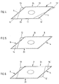
- FIG. 1 is shown schematically in plan view, a dust filter bag in the form of a flat bag 1 in a rectangular shape.
- a dust filter bag in the form of a flat bag 1 in a rectangular shape.
- 2 and 3 are not visible from the plan view folds, in the example after FIG. 1 are formed on the bag sides 4 and 5 in trapezoidal shape, symbolizes.
- an inlet opening 6 is provided in the middle of the flat bag 1.
- the shape of the flat bag 1 which is chosen here square, can of course also deviate from the square shape and be formed rectangular.
- the flat bag points a circumferential weld 11, which has been realized by means of ultrasonic welding, the material of the flat bag is a multilayer nonwoven material.
- FIG. 2 now shows the cross section according to the section line II in the embodiment according to FIG. 1 , FIG. 2 particularly clearly illustrates the folding 2, 3 according to the invention.
- the dust filter bag according to the embodiment according to FIG. 1 consists of a first layer 8 and a second layer 7 of the multilayer weldable material.
- the first layer 8 has a fold with the pleat legs 9, 10 or 9 ', 10'.
- the pleat legs 9, 10 and 9 ', 10' are designed so that they have an unequal length, wherein the larger of the pleat legs 9, 9 'forms a projection with respect to the layer 8.
- the folding according to the invention causes, when the filter bag is filled in the inserted state through the inlet opening 6 with dust-laden air, a puffing, so that then expand the folds 2, 3 with the pleat legs 9, 10 and 9 ', 10' and optionally turn outward so that an enlarged volume is created.
- FIG. 3 is the corresponding shape, which then results in fully everted state, shown schematically in plan view.
- the reference numerals 2 and 3 denote the everted folds, which form a trapezoidal shape.
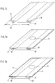
- FIG. 4 now shows a further embodiment of a flat bag according to the invention.
- flat bag after the FIG. 4 while the folding was designed so that they now on a bag side and indeed as here in FIG. 4 on the same side 23, at the edge welded to the weld 11, so that only one side on the side 24 a protuberance to form an outer fold 13, 13 'takes place and on the bag side 23, in which a fusion of the folds simultaneously with the circumferential weld 11 takes place, an inner fold 14, 14 'is formed, so that overall results in a conical configuration of the dust filter bag in the fully everted state.
- the manufacturing process for this purpose is in the FIG. 8 (Bag side 24) and FIG. 7 (Bag side 23) explained in more detail.
- FIG. 5 Now shows a further modification of the flat bag, in which a folding, as in FIG. 4 shown only on one side of the bag.
- FIG. 6 Yet another embodiment in which an offset arrangement of the outer folds 13 and 13 'has been performed by appropriate fixing on the sides 23 and 24 of the respective gussets, so that the outer folds 13, 13' are arranged offset.
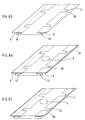
- FIG. 7 now shows in the figure sequence 7a to 7g a first manufacturing method for the flat bag according to the invention.
- a web-shaped sub-web made of a nonwoven fabric is provided in a first step.
- the dimensioning of this sub-web is selected in width (denoted by b) in such a way that, after folding, a width c is realized ( FIG. 7c ), which corresponds approximately to the then to be connected to the sublane upper web.
- FIG. 7a is indicated by the arrow the direction of the lower web.
- the procedure is such that, preferably, in a first step, the web-shaped lower web is folded over. This is in FIG. 7b shown.
- FIG. 7c shown a refolding performed so that a fold to form a first pleat leg 10 and a second pleat leg 9 and 9 'or 10'entsteht.
- the second pleat leg 9 or 9 ' which forms a supernatant, is chosen to be greater in its leg length than the pleat legs 10 and 10'.
- a top web is placed on the so-folded sub-web.
- the dimensioning of the top sheet is chosen so that the longitudinal edges are approximately flush with the edges of the pleat legs 9 and 9 '.
- the upper track is, as here in FIG. 7d already provided with a filling opening 6 and a holding plate (not shown).
- FIG. 7g For the completion of the filter bag, it is now only necessary at a predetermined distance Querversch spa 11, as shown in Figure 7f are shown to bring. Finally, a separation takes place in the region of the transverse welds 11, so that then a finished filter bag is formed ( FIG. 7g ).
- FIGS. 7a to 7g In the manufacturing process of the filter bag according to the invention, as described in the FIGS. 7a to 7g is shown, now creates a filter bag, in which folds 2, 3 are present, which are fixed in each case by the circumferential weld 11 on the bag sides 23, 24. In the operating state then takes place in the embodiment, as with the method of the FIG. 7 is realized, an expansion of the pleat legs or a protuberance.
- FIGS. 8a to 8h show a variant of the production method of the flat bag according to the invention.
- FIG. 8b shown after punching punched 30 introduced into the folded area.
- These cut-outs 30 are preferably welded circumferentially to form the weld 31 (see FIG. 8c ).
- FIG. 7d After welding the punched holes 30 then a refolding, as already in FIG. 7d is shown.
- Analogous to the procedure, as in the FIG. 7 has been described, followed by a laying of the upper web (8e) and a welding of the longitudinal edges to form the weld 11 (8f).
- the transverse weld 11 is selected is that they each leads through the corresponding punched 30.
- An embodiment is shown in which the punched-out portions 30 are arranged symmetrically and the respective transverse welds 11 are guided centrally through the punched-out portions 30.
- FIG. 8 produced flat bag corresponds to the flat bag after FIG. 1 ,
- FIGS. 8a to 8h likewise makes clear that the method according to the invention has great flexibility.
- dust filter bags are produced, which have shapes in the everting state, as in the FIGS. 4 to 6 have been shown.
- the inventive method thus has an extremely high flexibility with respect to the dust filter bag to be produced and at the same time is technically easy to perform.
Claims (22)
- Sac filtrant à poussières sous la forme d'un sac plat (1) pour un aspirateur, qui se compose d'une première couche (8) et d'une deuxième couche (7) en matériau soudable, les deux couches (7, 8) étant assemblées par soudage de façon périphérique le long de leur périmètre, et en ce qu'au moins une ouverture d'entrée (6) est mise en place dans une des deux couches,
caractérisé en ce que l'une des couches du sac plat est pliée vers l'intérieur de façon retroussable sur au moins un côté du sac vers l'intérieur du sac avec formation d'une première et d'une deuxième patte de pli (9, 9', 10, 10') qui sont de longueur inégale,
le pli intérieur (2 ou respectivement 3) formé par deux pattes de pli (9, 9', 10, 10') ne présentant respectivement pas de soudure. - Sac filtrant à poussières selon la revendication 1,
caractérisé en ce que, sur deux côtés opposés du sac (4, 5), la couche est respectivement pliée vers l'intérieur de façon retroussable. - Sac filtrant à poussières selon la revendication 1 ou 2,
caractérisé en ce que le plissage vers l'intérieur retroussable est constituée de telle sorte qu'il est essentiellement retroussable sur toute la largeur du/des côté(s) du sac (4, 5). - Sac filtrant à poussières selon la revendication 3,
caractérisé en ce que le plissage vers l'intérieur (2, 3) est constitué de telle sorte que, dans l'état entièrement retroussé, il forme un pli extérieur essentiellement trapézoïdal. - Sac filtrant à poussières selon la revendication 1 ou 2,
caractérisé en ce que le plissage vers l'intérieur (2, 3) retroussable est constitué de telle sorte qu'il n'est que partiellement retroussable sur la largeur du/des côté(s) du sac (4, 5). - Sac filtrant à poussières selon la revendication 5,
caractérisé en ce que le plissage vers l'intérieur est constitué de telle sorte que, dans l'état entièrement retroussé, il forme un pli extérieur (13, 13') essentiellement triangulaire. - Sac filtrant à poussières selon la revendication 5,
caractérisé en ce que, sur deux côtés opposés du sac (4, 5), les plis extérieurs (13, 13') sont disposés de façon opposée. - Sac filtrant à poussières selon au moins une des revendications 1 à 7, caractérisé en ce que le sac filtrant à poussières possède une forme rectangulaire ou carrée.
- Sac filtrant à poussières selon au moins une des revendications 1 à 8, caractérisé en ce que le matériau des couches du sac filtrant à poussières est un matériau non tissé.
- Sac filtrant à poussières selon la revendication 9,
caractérisé en ce que le matériau non tissé est un matériau composite constitué de plusieurs couches. - Sac filtrant à poussières selon au moins une des revendications 1 à 10, caractérisé en ce que l'ouverture d'entrée (6) au moins au nombre de un est renforcée par une plaque de retenue.
- Procédé de fabrication d'un sac plat filtrant à poussières (1) selon au moins une des revendications 1 à 11,
caractérisé en ce quea) il est fourni une bande inférieure en forme de bande avec une surface plus grande en vis-à-vis d'une bande supérieure en forme de bande,b) un plissage est réalisé dans la bande inférieure au moins sur un côté, avec formation d'une première (9) et d'une deuxième (10) patte de pli, la deuxième patte de pli (10) présentant une plus grande longueur de patte et formant une saillie,c) la bande supérieure est placée sur la bande inférieure,d) la bande inférieure est soudée dans la zone de bord de la saillie avec les bords longitudinaux de la bande supérieure,e) la bande inférieure est soudée de façon croisée avec la bande supérieure sur une distance prédéfinie, etf) une séparation intervient dans la zone des soudures croisées pour la formation du sac plat (1) avec une première (7) et une deuxième (8) couche. - Procédé selon la revendication 12,
caractérisé en ce que le plissage est réalisé sur deux côtés (4, 5) opposés de la bande inférieure en forme de bande. - Procédé selon la revendication 12 ou 13,
caractérisé en ce que, pour la formation du plissage vers l'intérieur (caractéristique b)) dans la bande inférieure, un rabat est effectué dans une première étape et, dans une deuxième étape, un sur-plissage est effectué avec formation d'une saillie. - Procédé selon la revendication 14,
caractérisé en ce que des découpes (30) sont réalisées dans la zone rabattue de la bande inférieure et leurs bords sont soudés entre eux au moins partiellement, et en ce que ensuite le sur-plissage est effectué. - Procédé selon la revendication 15,
caractérisé en ce que le nombre et l'espacement des découpes (30) dans la bande inférieure sont choisis de telle sorte que, dans le cas de la soudure croisée (caractéristique e)), au moins une soudure croisée traverse un évidement. - Procédé selon la revendication 16,
caractérisé en ce que les soudures croisées (caractéristique e)) traversent respectivement deux découpes (30) disposées de chaque côté. - Procédé selon au moins l'une des revendications 16 ou 17,
caractérisé en ce que les découpes (30) sont essentiellement trapézoïdales, triangulaires ou semi-circulaires. - Procédé selon au moins l'une des revendications 12 à 18,
caractérisé en ce qu'au moins une ouverture d'entrée (6) est mise en place dans la bande supérieure. - Procédé selon au moins l'une des revendications 12 à 19,
caractérisé en ce que les soudures croisées et la séparation (caractéristiques e) et f)) sont réalisées en une passe de travail. - Procédé selon au moins l'une des revendications 12 à 20,
caractérisé en ce que des pré-plis sont mis en place dans la bande inférieure pour assister les plissages vers l'intérieur. - Procédé selon au moins l'une des revendications 12 à 21,
caractérisé en ce que la soudure (11) est effectuée au moyen d'un soudage par ultrasons.
Applications Claiming Priority (2)
| Application Number | Priority Date | Filing Date | Title |
|---|---|---|---|
| DE102006023707A DE102006023707B3 (de) | 2006-05-19 | 2006-05-19 | Staubfilterbeutel |
| PCT/EP2007/004203 WO2007134734A1 (fr) | 2006-05-19 | 2007-05-11 | Sac à filtre antipoussière |
Publications (2)
| Publication Number | Publication Date |
|---|---|
| EP2018111A1 EP2018111A1 (fr) | 2009-01-28 |
| EP2018111B1 true EP2018111B1 (fr) | 2016-02-03 |
Family
ID=38330445
Family Applications (1)
| Application Number | Title | Priority Date | Filing Date |
|---|---|---|---|
| EP07725123.9A Active EP2018111B1 (fr) | 2006-05-19 | 2007-05-11 | Sac à filtre antipoussière |
Country Status (8)
| Country | Link |
|---|---|
| US (1) | US8097054B2 (fr) |
| EP (1) | EP2018111B1 (fr) |
| CN (1) | CN101448446B (fr) |
| AU (1) | AU2007251981B2 (fr) |
| DE (1) | DE102006023707B3 (fr) |
| ES (1) | ES2564245T3 (fr) |
| NO (1) | NO341014B1 (fr) |
| WO (1) | WO2007134734A1 (fr) |
Families Citing this family (13)
| Publication number | Priority date | Publication date | Assignee | Title |
|---|---|---|---|---|
| DE102008006769B4 (de) | 2008-01-30 | 2013-08-08 | Arwed Löseke Papierverarbeitung und Druckerei GmbH | Verfahren zur Herstellung eines Staubfilterbeutels mit Seitenfalten |
| EP2266450B1 (fr) * | 2009-06-24 | 2016-09-21 | Eurofilters N.V. | Filtre sac à fond plat pour aspirateurs |
| US8075649B2 (en) * | 2009-12-01 | 2011-12-13 | Zenith Technologies, Llc | Vacuum bag and vacuum bag attachment assembly |
| DK2359730T4 (da) | 2010-02-19 | 2019-11-11 | Eurofilters Holding Nv | Støvsugerfilterpose med sidefold |
| PL2366319T3 (pl) * | 2010-03-19 | 2015-07-31 | Eurofilters Holding Nv | Worek filtrujący do odkurzacza |
| CN102599857B (zh) * | 2011-01-19 | 2014-07-30 | 泰怡凯电器(苏州)有限公司 | 真空吸尘器集尘袋 |
| DK2502538T3 (en) | 2011-03-22 | 2015-12-07 | Eurofilters Holding Nv | Vacuum cleaner filter bag with filterposevægforbindelsesindretning |
| DK2502536T3 (en) | 2011-03-22 | 2019-04-01 | Eurofilters Nv | Ecologically efficient device for vacuuming |
| EP2929822B1 (fr) * | 2014-04-08 | 2017-02-22 | Eurofilters N.V. | Sac d'aspirateur pour aspirateur vertical |
| BE1023374B1 (nl) * | 2015-08-24 | 2017-02-24 | Sac O2 Nv | Werkwijze en inrichting voor het op een onderdeel van een recipiënt aanbrengen van een gasfilter |
| ES2916748T3 (es) * | 2015-12-12 | 2022-07-05 | Procedimiento para producir una unión por material entre una placa de retención y la pared de una bolsa de filtro de aspiradora, así como bolsa de filtro de aspiradora | |
| US10513450B2 (en) | 2016-06-23 | 2019-12-24 | Colgate-Palmolive Company | Wastewater filtration system |
| CN115416320B (zh) * | 2022-11-02 | 2023-01-24 | 常州凯士多医疗科技有限公司 | 一种取样钳输送系统及上料方法 |
Family Cites Families (12)
| Publication number | Priority date | Publication date | Assignee | Title |
|---|---|---|---|---|
| US3491522A (en) * | 1967-05-22 | 1970-01-27 | Studley Paper Co | Vacuum cleaner filter bag |
| US3430843A (en) * | 1967-11-13 | 1969-03-04 | Studley Paper Co | Disposable filter bag |
| US3596443A (en) * | 1969-10-29 | 1971-08-03 | Modern Dust Bag Co Inc | Vacuum cleaner filter bag |
| US3738091A (en) * | 1971-05-24 | 1973-06-12 | Studley Paper Co | Vacuum cleaner filter bag |
| US6251154B1 (en) * | 1992-05-06 | 2001-06-26 | 3M Innovative Properties Company | Dust bag and method of production |
| SE501135C2 (sv) * | 1993-07-07 | 1994-11-21 | Maj Britt Hulthen | Dammbehållare för dammsugare |
| DE19832611C2 (de) * | 1998-07-21 | 2002-03-21 | Freudenberg Carl Kg | Staubfilterbeutel |
| SE520872C2 (sv) * | 1999-04-28 | 2003-09-09 | Electrolux Ab | Dammbehållare |
| EP1059056B1 (fr) * | 1999-06-08 | 2004-11-03 | 3M Innovative Properties Company | Sac à poussières et procédé pour le fabriquer |
| DE20101466U1 (de) | 2001-01-27 | 2001-04-19 | Wolf Gmbh | In einen Staubsauger einsetzbare Filtereinrichtung |
| DE202005000917U1 (de) | 2005-01-20 | 2005-03-24 | Branofilter Gmbh | Staubfilterbeutel |
| DE202005016309U1 (de) * | 2005-10-18 | 2005-12-15 | Wolf Gmbh | Staubsaugerbeutel |
-
2006
- 2006-05-19 DE DE102006023707A patent/DE102006023707B3/de active Active
-
2007
- 2007-05-11 WO PCT/EP2007/004203 patent/WO2007134734A1/fr active Application Filing
- 2007-05-11 US US12/299,069 patent/US8097054B2/en active Active
- 2007-05-11 AU AU2007251981A patent/AU2007251981B2/en active Active
- 2007-05-11 CN CN2007800181857A patent/CN101448446B/zh active Active
- 2007-05-11 ES ES07725123.9T patent/ES2564245T3/es active Active
- 2007-05-11 EP EP07725123.9A patent/EP2018111B1/fr active Active
-
2008
- 2008-11-17 NO NO20084831A patent/NO341014B1/no not_active IP Right Cessation
Also Published As
| Publication number | Publication date |
|---|---|
| NO20084831L (no) | 2009-02-19 |
| EP2018111A1 (fr) | 2009-01-28 |
| ES2564245T3 (es) | 2016-03-21 |
| NO341014B1 (no) | 2017-08-07 |
| CN101448446A (zh) | 2009-06-03 |
| US8097054B2 (en) | 2012-01-17 |
| AU2007251981B2 (en) | 2011-09-08 |
| AU2007251981A1 (en) | 2007-11-29 |
| WO2007134734A1 (fr) | 2007-11-29 |
| DE102006023707B3 (de) | 2008-01-03 |
| CN101448446B (zh) | 2012-02-01 |
| US20090308032A1 (en) | 2009-12-17 |
Similar Documents
| Publication | Publication Date | Title |
|---|---|---|
| EP2018111B1 (fr) | Sac à filtre antipoussière | |
| EP1683460B1 (fr) | Sac filtrant à poussières | |
| EP2366320B1 (fr) | Sac d'aspirateur | |
| DE10348375B4 (de) | Filterbeutel und Verfahren zu dessen Herstellung | |
| EP0261488B1 (fr) | Feutre pour papeterie et son procédé de fabrication | |
| EP0974387A1 (fr) | Sac filtrant à poussiéres | |
| DE10235275A1 (de) | Filterelement und Verfahren zu dessen Herstellung | |
| DE102009054077A1 (de) | Verfahren zum Herstellen eines Filterelementes | |
| EP0897029B1 (fr) | Tricot entretoise et couvercle de compartiment à baggage ou charge pour des véhicules automobiles produit à partir de celui-ci | |
| EP1928288B1 (fr) | Sac pour aspirateur et procede de production de ce sac | |
| EP2929822B1 (fr) | Sac d'aspirateur pour aspirateur vertical | |
| DE102008016596B4 (de) | Staubfilterbeutel für Staubsauger | |
| EP2359730B2 (fr) | Sac d'aspirateur doté d'un volet latéral | |
| WO1996005986A1 (fr) | Procede de production d'un corps creux pour airbag | |
| EP1212971B1 (fr) | Sac à poussières pour aspirateur | |
| EP2465397B1 (fr) | Sac d'aspirateur et procédé destiné à la fabrication d'un sac d'aspirateur | |
| DE102009005306B4 (de) | Airbag und Verfahren zu dessen Herstellung | |
| DE102011120688A1 (de) | Staubfilterbeutel mit einer Staubfängereinlage | |
| DE102017111837A1 (de) | Staubfilterbeutel mit Mehrfachfalte | |
| DE202011108953U1 (de) | Staubfilterbeutel mit einer Staubfängereinlage | |
| EP1812134B1 (fr) | Element filtrant cylindrique creux pour fluides liquides ou gazeux | |
| DE202010013156U1 (de) | Staubsaugerbeutel | |
| DE202005020237U1 (de) | Zylinderförmiges Filter | |
| DE102007005612A1 (de) | Filterbeutel für einen Staubsauger | |
| DE102011109571A1 (de) | Verfahren zur Herstellung eines dreidimensionalen Gassacks und dreidimensionaler Gassack für eine Fahrzeuginsassen-Rückhaltevorrichtung |
Legal Events
| Date | Code | Title | Description |
|---|---|---|---|
| PUAI | Public reference made under article 153(3) epc to a published international application that has entered the european phase |
Free format text: ORIGINAL CODE: 0009012 |
|
| 17P | Request for examination filed |
Effective date: 20081110 |
|
| AK | Designated contracting states |
Kind code of ref document: A1 Designated state(s): AT BE BG CH CY CZ DE DK EE ES FI FR GB GR HU IE IS IT LI LT LU LV MC MT NL PL PT RO SE SI SK TR |
|
| AX | Request for extension of the european patent |
Extension state: AL BA HR MK RS |
|
| 17Q | First examination report despatched |
Effective date: 20100730 |
|
| DAX | Request for extension of the european patent (deleted) | ||
| GRAP | Despatch of communication of intention to grant a patent |
Free format text: ORIGINAL CODE: EPIDOSNIGR1 |
|
| INTG | Intention to grant announced |
Effective date: 20150810 |
|
| GRAS | Grant fee paid |
Free format text: ORIGINAL CODE: EPIDOSNIGR3 |
|
| RIN1 | Information on inventor provided before grant (corrected) |
Inventor name: SCHULTINK, JAN Inventor name: SAUER, RALF |
|
| GRAA | (expected) grant |
Free format text: ORIGINAL CODE: 0009210 |
|
| INTG | Intention to grant announced |
Effective date: 20151209 |
|
| AK | Designated contracting states |
Kind code of ref document: B1 Designated state(s): AT BE BG CH CY CZ DE DK EE ES FI FR GB GR HU IE IS IT LI LT LU LV MC MT NL PL PT RO SE SI SK TR |
|
| REG | Reference to a national code |
Ref country code: GB Ref legal event code: FG4D Free format text: NOT ENGLISH |
|
| REG | Reference to a national code |
Ref country code: AT Ref legal event code: REF Ref document number: 773263 Country of ref document: AT Kind code of ref document: T Effective date: 20160215 Ref country code: CH Ref legal event code: EP |
|
| REG | Reference to a national code |
Ref country code: IE Ref legal event code: FG4D Free format text: LANGUAGE OF EP DOCUMENT: GERMAN |
|
| REG | Reference to a national code |
Ref country code: DE Ref legal event code: R096 Ref document number: 502007014544 Country of ref document: DE |
|
| REG | Reference to a national code |
Ref country code: ES Ref legal event code: FG2A Ref document number: 2564245 Country of ref document: ES Kind code of ref document: T3 Effective date: 20160321 |
|
| REG | Reference to a national code |
Ref country code: SE Ref legal event code: TRGR |
|
| REG | Reference to a national code |
Ref country code: NL Ref legal event code: FP |
|
| REG | Reference to a national code |
Ref country code: FR Ref legal event code: PLFP Year of fee payment: 10 |
|
| REG | Reference to a national code |
Ref country code: LT Ref legal event code: MG4D |
|
| PG25 | Lapsed in a contracting state [announced via postgrant information from national office to epo] |
Ref country code: FI Free format text: LAPSE BECAUSE OF FAILURE TO SUBMIT A TRANSLATION OF THE DESCRIPTION OR TO PAY THE FEE WITHIN THE PRESCRIBED TIME-LIMIT Effective date: 20160203 Ref country code: GR Free format text: LAPSE BECAUSE OF FAILURE TO SUBMIT A TRANSLATION OF THE DESCRIPTION OR TO PAY THE FEE WITHIN THE PRESCRIBED TIME-LIMIT Effective date: 20160504 |
|
| PG25 | Lapsed in a contracting state [announced via postgrant information from national office to epo] |
Ref country code: PT Free format text: LAPSE BECAUSE OF FAILURE TO SUBMIT A TRANSLATION OF THE DESCRIPTION OR TO PAY THE FEE WITHIN THE PRESCRIBED TIME-LIMIT Effective date: 20160603 Ref country code: IS Free format text: LAPSE BECAUSE OF FAILURE TO SUBMIT A TRANSLATION OF THE DESCRIPTION OR TO PAY THE FEE WITHIN THE PRESCRIBED TIME-LIMIT Effective date: 20160603 Ref country code: LV Free format text: LAPSE BECAUSE OF FAILURE TO SUBMIT A TRANSLATION OF THE DESCRIPTION OR TO PAY THE FEE WITHIN THE PRESCRIBED TIME-LIMIT Effective date: 20160203 Ref country code: LT Free format text: LAPSE BECAUSE OF FAILURE TO SUBMIT A TRANSLATION OF THE DESCRIPTION OR TO PAY THE FEE WITHIN THE PRESCRIBED TIME-LIMIT Effective date: 20160203 Ref country code: PL Free format text: LAPSE BECAUSE OF FAILURE TO SUBMIT A TRANSLATION OF THE DESCRIPTION OR TO PAY THE FEE WITHIN THE PRESCRIBED TIME-LIMIT Effective date: 20160203 |
|
| PG25 | Lapsed in a contracting state [announced via postgrant information from national office to epo] |
Ref country code: DK Free format text: LAPSE BECAUSE OF FAILURE TO SUBMIT A TRANSLATION OF THE DESCRIPTION OR TO PAY THE FEE WITHIN THE PRESCRIBED TIME-LIMIT Effective date: 20160203 Ref country code: EE Free format text: LAPSE BECAUSE OF FAILURE TO SUBMIT A TRANSLATION OF THE DESCRIPTION OR TO PAY THE FEE WITHIN THE PRESCRIBED TIME-LIMIT Effective date: 20160203 |
|
| REG | Reference to a national code |
Ref country code: DE Ref legal event code: R097 Ref document number: 502007014544 Country of ref document: DE |
|
| PG25 | Lapsed in a contracting state [announced via postgrant information from national office to epo] |
Ref country code: CZ Free format text: LAPSE BECAUSE OF FAILURE TO SUBMIT A TRANSLATION OF THE DESCRIPTION OR TO PAY THE FEE WITHIN THE PRESCRIBED TIME-LIMIT Effective date: 20160203 Ref country code: RO Free format text: LAPSE BECAUSE OF FAILURE TO SUBMIT A TRANSLATION OF THE DESCRIPTION OR TO PAY THE FEE WITHIN THE PRESCRIBED TIME-LIMIT Effective date: 20160203 Ref country code: SK Free format text: LAPSE BECAUSE OF FAILURE TO SUBMIT A TRANSLATION OF THE DESCRIPTION OR TO PAY THE FEE WITHIN THE PRESCRIBED TIME-LIMIT Effective date: 20160203 |
|
| PLBE | No opposition filed within time limit |
Free format text: ORIGINAL CODE: 0009261 |
|
| STAA | Information on the status of an ep patent application or granted ep patent |
Free format text: STATUS: NO OPPOSITION FILED WITHIN TIME LIMIT |
|
| 26N | No opposition filed |
Effective date: 20161104 |
|
| REG | Reference to a national code |
Ref country code: IE Ref legal event code: MM4A |
|
| PG25 | Lapsed in a contracting state [announced via postgrant information from national office to epo] |
Ref country code: BG Free format text: LAPSE BECAUSE OF FAILURE TO SUBMIT A TRANSLATION OF THE DESCRIPTION OR TO PAY THE FEE WITHIN THE PRESCRIBED TIME-LIMIT Effective date: 20160503 Ref country code: SI Free format text: LAPSE BECAUSE OF FAILURE TO SUBMIT A TRANSLATION OF THE DESCRIPTION OR TO PAY THE FEE WITHIN THE PRESCRIBED TIME-LIMIT Effective date: 20160203 |
|
| REG | Reference to a national code |
Ref country code: FR Ref legal event code: PLFP Year of fee payment: 11 |
|
| PG25 | Lapsed in a contracting state [announced via postgrant information from national office to epo] |
Ref country code: IE Free format text: LAPSE BECAUSE OF NON-PAYMENT OF DUE FEES Effective date: 20160511 |
|
| REG | Reference to a national code |
Ref country code: FR Ref legal event code: PLFP Year of fee payment: 12 |
|
| PG25 | Lapsed in a contracting state [announced via postgrant information from national office to epo] |
Ref country code: CY Free format text: LAPSE BECAUSE OF FAILURE TO SUBMIT A TRANSLATION OF THE DESCRIPTION OR TO PAY THE FEE WITHIN THE PRESCRIBED TIME-LIMIT Effective date: 20160203 Ref country code: HU Free format text: LAPSE BECAUSE OF FAILURE TO SUBMIT A TRANSLATION OF THE DESCRIPTION OR TO PAY THE FEE WITHIN THE PRESCRIBED TIME-LIMIT; INVALID AB INITIO Effective date: 20070511 |
|
| PG25 | Lapsed in a contracting state [announced via postgrant information from national office to epo] |
Ref country code: MC Free format text: LAPSE BECAUSE OF FAILURE TO SUBMIT A TRANSLATION OF THE DESCRIPTION OR TO PAY THE FEE WITHIN THE PRESCRIBED TIME-LIMIT Effective date: 20160203 Ref country code: MT Free format text: LAPSE BECAUSE OF FAILURE TO SUBMIT A TRANSLATION OF THE DESCRIPTION OR TO PAY THE FEE WITHIN THE PRESCRIBED TIME-LIMIT Effective date: 20160203 |
|
| REG | Reference to a national code |
Ref country code: DE Ref legal event code: R082 Ref document number: 502007014544 Country of ref document: DE Representative=s name: GRUENECKER PATENT- UND RECHTSANWAELTE PARTG MB, DE |
|
| PGFP | Annual fee paid to national office [announced via postgrant information from national office to epo] |
Ref country code: LU Payment date: 20220531 Year of fee payment: 16 |
|
| PGFP | Annual fee paid to national office [announced via postgrant information from national office to epo] |
Ref country code: TR Payment date: 20220506 Year of fee payment: 16 Ref country code: CH Payment date: 20220519 Year of fee payment: 16 Ref country code: AT Payment date: 20220523 Year of fee payment: 16 |
|
| PGFP | Annual fee paid to national office [announced via postgrant information from national office to epo] |
Ref country code: ES Payment date: 20220725 Year of fee payment: 16 |
|
| PGFP | Annual fee paid to national office [announced via postgrant information from national office to epo] |
Ref country code: NL Payment date: 20230525 Year of fee payment: 17 Ref country code: IT Payment date: 20230529 Year of fee payment: 17 Ref country code: FR Payment date: 20230525 Year of fee payment: 17 Ref country code: DE Payment date: 20230526 Year of fee payment: 17 |
|
| PGFP | Annual fee paid to national office [announced via postgrant information from national office to epo] |
Ref country code: SE Payment date: 20230525 Year of fee payment: 17 |
|
| PGFP | Annual fee paid to national office [announced via postgrant information from national office to epo] |
Ref country code: BE Payment date: 20230525 Year of fee payment: 17 |
|
| PGFP | Annual fee paid to national office [announced via postgrant information from national office to epo] |
Ref country code: GB Payment date: 20230525 Year of fee payment: 17 |
|
| REG | Reference to a national code |
Ref country code: CH Ref legal event code: PL |
|
| REG | Reference to a national code |
Ref country code: AT Ref legal event code: MM01 Ref document number: 773263 Country of ref document: AT Kind code of ref document: T Effective date: 20230511 |
|
| PG25 | Lapsed in a contracting state [announced via postgrant information from national office to epo] |
Ref country code: LU Free format text: LAPSE BECAUSE OF NON-PAYMENT OF DUE FEES Effective date: 20230511 Ref country code: LI Free format text: LAPSE BECAUSE OF NON-PAYMENT OF DUE FEES Effective date: 20230531 Ref country code: CH Free format text: LAPSE BECAUSE OF NON-PAYMENT OF DUE FEES Effective date: 20230531 Ref country code: AT Free format text: LAPSE BECAUSE OF NON-PAYMENT OF DUE FEES Effective date: 20230511 |