EP2017905A2 - Stellantrieb - Google Patents
Stellantrieb Download PDFInfo
- Publication number
- EP2017905A2 EP2017905A2 EP08160022A EP08160022A EP2017905A2 EP 2017905 A2 EP2017905 A2 EP 2017905A2 EP 08160022 A EP08160022 A EP 08160022A EP 08160022 A EP08160022 A EP 08160022A EP 2017905 A2 EP2017905 A2 EP 2017905A2
- Authority
- EP
- European Patent Office
- Prior art keywords
- vibrator
- piezoelectric element
- vibration
- electrode
- supporting member
- Prior art date
- Legal status (The legal status is an assumption and is not a legal conclusion. Google has not performed a legal analysis and makes no representation as to the accuracy of the status listed.)
- Granted
Links
Images




Classifications
-
- H—ELECTRICITY
- H02—GENERATION; CONVERSION OR DISTRIBUTION OF ELECTRIC POWER
- H02N—ELECTRIC MACHINES NOT OTHERWISE PROVIDED FOR
- H02N2/00—Electric machines in general using piezoelectric effect, electrostriction or magnetostriction
- H02N2/0005—Electric machines in general using piezoelectric effect, electrostriction or magnetostriction producing non-specific motion; Details common to machines covered by H02N2/02 - H02N2/16
- H02N2/009—Thermal details, e.g. cooling means
-
- H—ELECTRICITY
- H02—GENERATION; CONVERSION OR DISTRIBUTION OF ELECTRIC POWER
- H02N—ELECTRIC MACHINES NOT OTHERWISE PROVIDED FOR
- H02N2/00—Electric machines in general using piezoelectric effect, electrostriction or magnetostriction
- H02N2/02—Electric machines in general using piezoelectric effect, electrostriction or magnetostriction producing linear motion, e.g. actuators; Linear positioners ; Linear motors
- H02N2/021—Electric machines in general using piezoelectric effect, electrostriction or magnetostriction producing linear motion, e.g. actuators; Linear positioners ; Linear motors using intermittent driving, e.g. step motors, piezoleg motors
-
- H—ELECTRICITY
- H02—GENERATION; CONVERSION OR DISTRIBUTION OF ELECTRIC POWER
- H02N—ELECTRIC MACHINES NOT OTHERWISE PROVIDED FOR
- H02N2/00—Electric machines in general using piezoelectric effect, electrostriction or magnetostriction
- H02N2/02—Electric machines in general using piezoelectric effect, electrostriction or magnetostriction producing linear motion, e.g. actuators; Linear positioners ; Linear motors
- H02N2/08—Electric machines in general using piezoelectric effect, electrostriction or magnetostriction producing linear motion, e.g. actuators; Linear positioners ; Linear motors using travelling waves, i.e. Rayleigh surface waves
Definitions
- actuators using a vibrator and a piezoelectric element some configurations, such as an ultrasonic motor, are known.
- realization of movement of fingertips of a robot hand using the actuators requires realization of a small linear motion mechanism, which corresponds to the human muscle.
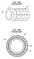
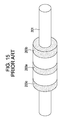
- a contact force for keeping a vibrator close to a stator is needed. If this contact force is too weak, the friction force, namely, the driving force, decreases. If the contact force is too strong, the force disturbs vibration of the vibrator and decreases the durability undesirably. Accordingly, it is important to keep the contact force constant in vibration actuators. In the case of cylindrical linear actuators, this contact force is compensated by a fitting accuracy of the vibrator and a circular tube serving as a stator.
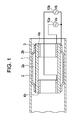
- Figs. 2A to 2C are schematic diagrams illustrating a state where a traveling wave is generated in an actuator shown in Fig. 1 .
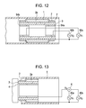
- Fig. 10 is a sectional view showing a modified example of an actuator according to a fourth exemplary embodiment of the present invention.
- Figs. 2A to 2C are schematic diagrams illustrating a principle of converting vibration of the vibrator 2 into a driving force. Figs. 2A to 2C exaggeratedly show the vibration amplitude for the purpose of explanation. Referring to Fig. 2A , a sine-wave vibration voltage Va is applied across the first electrode 4a and the vibrator 2 by the alternating power supply 10a.
- the mover including the vibrator 2 and the piezoelectric element 3 is relatively moved in the axial direction of the tubular member 1 utilizing this traveling wave.
- a traveling wave a wave whose wave front travels in one direction
- a standing wave a wave whose wave front does not travel due to an interference with a wave reflected at an end portion.
- the vibration has to be absorbed at the end portion opposite to the vibration-generating side.
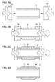
- second caps 13 are then put on the respective ends of the piezoelectric element 3.
- a film serving as the vibrator 2 is formed on the sacrificial layer 12 while rotating the piezoelectric element 3.
- a material highly resistant to repeatedly applied stress is preferable as a material of the vibrator 2.
- a material of stainless series or a material of metallic glass series is preferable.
- the metallic glass is composed of amorphous metal atoms. Since the metallic glass is amorphous, the metallic glass shows high durability unlike a normal metal. More specifically, the amorphous has a high hardness and can improve the abrasion resistance. In addition, manufacture of the tubular member 1 with the metallic glass can improve the abrasion resistance. As a result, an actuator having much higher durability can be realized.
- the air pressure may prevent the vibrator 2 from being in contact with the tubular member 1. This phenomenon is called ultrasonic levitation.
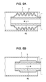
- the plurality of minute holes formed in the vibrator 2 can prevent this ultrasonic levitation.
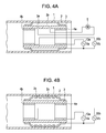
- holes 3a are formed on the piezoelectric element 3 in advance and may be filled with the same material as the sacrificial layer 12, as shown in Fig. 4A .
- the refrigerant can be circulated through the gap 2a. If the piezoelectric element 3 is vibrated at a high speed and a large amplitude, an amount of generated heat increases. By introducing the refrigerant to the gap 2a between the piezoelectric element 3 and the vibrator 2, this heat can be removed. As a result, an increase in the temperature of the piezoelectric element 3 and the vibrator 2 can be suppressed.
- a difference between Fig. 7 and Fig. 1 is that the first electrode 4a and the second electrode 4b are replaced with an electrode 4 which is formed on an inner surface of a piezoelectric element 3 in Fig. 7 .
- a vibration voltage V1 of an alternating power supply 40a and a vibration voltage V2 of an alternating power supply 40b are combined by an adding circuit 6 and are applied across a vibrator 2 and the electrode 4 as a third vibration voltage V3. Accordingly, the third vibration voltage V3 is applied to both ends of the vibrator 2.
- the first vibration voltage V1 is applied at the time of shrinkage of the piezoelectric element 3 in the direction of the arrow Rb and the level of the first vibration voltage V1 is lowered at the time of expansion of the piezoelectric element 3 in the direction of the arrow Ra. Accordingly, the moving direction can be changed by changing the phases of two kinds of vibration voltage V1 and V2.
Landscapes
- General Electrical Machinery Utilizing Piezoelectricity, Electrostriction Or Magnetostriction (AREA)
Applications Claiming Priority (2)
| Application Number | Priority Date | Filing Date | Title |
|---|---|---|---|
| JP2007189001 | 2007-07-20 | ||
| JP2008155357A JP5159452B2 (ja) | 2007-07-20 | 2008-06-13 | アクチュエータ |
Publications (3)
| Publication Number | Publication Date |
|---|---|
| EP2017905A2 true EP2017905A2 (de) | 2009-01-21 |
| EP2017905A3 EP2017905A3 (de) | 2012-07-11 |
| EP2017905B1 EP2017905B1 (de) | 2014-03-19 |
Family
ID=39855118
Family Applications (1)
| Application Number | Title | Priority Date | Filing Date |
|---|---|---|---|
| EP08160022.3A Ceased EP2017905B1 (de) | 2007-07-20 | 2008-07-09 | Stellantrieb |
Country Status (2)
| Country | Link |
|---|---|
| US (1) | US7915787B2 (de) |
| EP (1) | EP2017905B1 (de) |
Cited By (1)
| Publication number | Priority date | Publication date | Assignee | Title |
|---|---|---|---|---|
| CN107041120A (zh) * | 2017-05-12 | 2017-08-11 | 广州中国科学院先进技术研究所 | 一种慢波组件管壳冷挤压装置 |
Families Citing this family (12)
| Publication number | Priority date | Publication date | Assignee | Title |
|---|---|---|---|---|
| CN101160711B (zh) * | 2005-12-05 | 2013-03-20 | 松下电器产业株式会社 | 超声波致动器 |
| DE102008023478A1 (de) * | 2007-11-08 | 2009-05-14 | Physik Instrumente (Pi) Gmbh & Co. Kg | Ultraschalllinearantrieb mit hohlzylindrischem Oszillator |
| JP4677493B2 (ja) * | 2008-01-22 | 2011-04-27 | キヤノン株式会社 | 圧電振動型力センサ |
| DE102008057389B4 (de) * | 2008-11-14 | 2011-03-17 | Fraunhofer-Gesellschaft zur Förderung der angewandten Forschung e.V. | Transport eines Objekts über eine Oberfläche |
| JP5429141B2 (ja) * | 2010-01-19 | 2014-02-26 | Tdk株式会社 | 圧電アクチュエータ及び圧電アクチュエータの製造方法 |
| JP5743495B2 (ja) * | 2010-11-05 | 2015-07-01 | キヤノン株式会社 | ロボット制御装置 |
| JP5884303B2 (ja) * | 2011-06-07 | 2016-03-15 | セイコーエプソン株式会社 | 圧電アクチュエーター、ロボットハンド、及びロボット |
| JP5896789B2 (ja) | 2012-03-07 | 2016-03-30 | キヤノン株式会社 | ロボット制御装置、ロボット装置、ロボット制御方法、プログラム及び記録媒体 |
| JP6238628B2 (ja) | 2013-08-06 | 2017-11-29 | キヤノン株式会社 | ロボット装置、ロボット制御方法、ロボット制御プログラム及びロボット装置を用いた部品の製造方法 |
| JP6700669B2 (ja) | 2015-04-07 | 2020-05-27 | キヤノン株式会社 | 制御方法、ロボット装置、プログラム、記録媒体、及び物品の製造方法 |
| US11045950B2 (en) | 2018-11-02 | 2021-06-29 | Canon Kabushiki Kaisha | Driving device and detecting device |
| US11193354B2 (en) * | 2018-12-07 | 2021-12-07 | Baker Hughes Holdings Llc | Motors for downhole tools devices and related methods |
Citations (3)
| Publication number | Priority date | Publication date | Assignee | Title |
|---|---|---|---|---|
| JPH0472471A (ja) | 1990-07-11 | 1992-03-06 | Toshiba Corp | 給水加熱器ドレンポンプアップ系統 |
| JPH0549273A (ja) | 1991-08-06 | 1993-02-26 | Seiko Epson Corp | 超音波リニアモータ |
| JPH10210776A (ja) | 1997-01-27 | 1998-08-07 | Toshiba Corp | 回転直動一体型超音波モータ及びそれを内蔵した電子機器 |
Family Cites Families (9)
| Publication number | Priority date | Publication date | Assignee | Title |
|---|---|---|---|---|
| AT384912B (de) * | 1982-04-16 | 1988-01-25 | Ki Polt I | Piezoelektrischer motor |
| US4560263A (en) * | 1982-12-03 | 1985-12-24 | Canon Kabushiki Kaisha | Drive system for a vibration wave motor for lens control |
| JP2687233B2 (ja) * | 1989-02-10 | 1997-12-08 | キヤノン株式会社 | シート送り装置 |
| US5332941A (en) * | 1992-02-21 | 1994-07-26 | Honda Electronics Co., Ltd. | Ultrasonic driving motor |
| US5396142A (en) * | 1994-01-24 | 1995-03-07 | Evan Koblanski | Positioning apparatus |
| JPH10337057A (ja) * | 1997-06-02 | 1998-12-18 | Minolta Co Ltd | 駆動装置 |
| DE50014572D1 (de) * | 1999-11-29 | 2007-09-27 | Miniswys Sa | Piezoelektrischer antrieb |
| ATE335302T1 (de) * | 2002-03-15 | 2006-08-15 | Miniswys Sa | Piezoelektrischer motor und verfahren zum antrieb desselben |
| KR101138397B1 (ko) * | 2005-09-27 | 2012-04-26 | 삼성전자주식회사 | 압전 액츄에이터, 이의 구동 장치 및 방법 |
-
2008
- 2008-07-08 US US12/169,575 patent/US7915787B2/en not_active Expired - Fee Related
- 2008-07-09 EP EP08160022.3A patent/EP2017905B1/de not_active Ceased
Patent Citations (3)
| Publication number | Priority date | Publication date | Assignee | Title |
|---|---|---|---|---|
| JPH0472471A (ja) | 1990-07-11 | 1992-03-06 | Toshiba Corp | 給水加熱器ドレンポンプアップ系統 |
| JPH0549273A (ja) | 1991-08-06 | 1993-02-26 | Seiko Epson Corp | 超音波リニアモータ |
| JPH10210776A (ja) | 1997-01-27 | 1998-08-07 | Toshiba Corp | 回転直動一体型超音波モータ及びそれを内蔵した電子機器 |
Cited By (1)
| Publication number | Priority date | Publication date | Assignee | Title |
|---|---|---|---|---|
| CN107041120A (zh) * | 2017-05-12 | 2017-08-11 | 广州中国科学院先进技术研究所 | 一种慢波组件管壳冷挤压装置 |
Also Published As
| Publication number | Publication date |
|---|---|
| EP2017905B1 (de) | 2014-03-19 |
| US7915787B2 (en) | 2011-03-29 |
| US20090021113A1 (en) | 2009-01-22 |
| EP2017905A3 (de) | 2012-07-11 |
Similar Documents
| Publication | Publication Date | Title |
|---|---|---|
| EP2017905B1 (de) | Stellantrieb | |
| JP5159452B2 (ja) | アクチュエータ | |
| Watson et al. | Piezoelectric ultrasonic micro/milli-scale actuators | |
| CN102215010B (zh) | 振动型致动器、振动器以及振动器的制造方法 | |
| JP4943618B2 (ja) | 振動モータ、並びにその製造および使用の方法 | |
| US20030234596A1 (en) | Near-resonance electromechanical motor | |
| JP2012500503A (ja) | 準共振駆動システムおよびその方法 | |
| JPH10262381A (ja) | 交番電圧パターンを用いる静電アクチュエータ | |
| EP3319219A1 (de) | Ultraschallaktuator | |
| JP4435695B2 (ja) | 圧電モータの動作方法および固定子を有する中空円筒形の発振器の形状をなす圧電モータ | |
| US11050364B2 (en) | Semi-resonant motion devices and methods thereof | |
| JP5218045B2 (ja) | 振動アクチュエータ、レンズ鏡筒、カメラシステム及び振動アクチュエータの駆動方法 | |
| US5831370A (en) | Vibration actuator | |
| JP4871594B2 (ja) | 振動波駆動装置及び振動波駆動機器 | |
| JPH08140377A (ja) | 超音波アクチュエータ | |
| EP4275462B1 (de) | Anordnung zur befestigung eines piezomotorelements | |
| JP2010206950A (ja) | アクチュエータ | |
| KR100661311B1 (ko) | 압전 초음파 모터 | |
| JP4491888B2 (ja) | 振動アクチュエータ | |
| JP3074379B2 (ja) | 回転型圧電アクチュエータ | |
| JP2009055779A (ja) | 超音波アクチュエータ、磁気記録装置 | |
| JPH09205782A (ja) | 振動アクチュエータ駆動装置 | |
| JP2004289894A (ja) | 超音波モータ | |
| CN120212361A (zh) | 一种石油管道巡检机器人及其激励方法 | |
| JPH0635676Y2 (ja) | 超音波リニアモータ |
Legal Events
| Date | Code | Title | Description |
|---|---|---|---|
| PUAI | Public reference made under article 153(3) epc to a published international application that has entered the european phase |
Free format text: ORIGINAL CODE: 0009012 |
|
| AK | Designated contracting states |
Kind code of ref document: A2 Designated state(s): AT BE BG CH CY CZ DE DK EE ES FI FR GB GR HR HU IE IS IT LI LT LU LV MC MT NL NO PL PT RO SE SI SK TR |
|
| AX | Request for extension of the european patent |
Extension state: AL BA MK RS |
|
| PUAL | Search report despatched |
Free format text: ORIGINAL CODE: 0009013 |
|
| AK | Designated contracting states |
Kind code of ref document: A3 Designated state(s): AT BE BG CH CY CZ DE DK EE ES FI FR GB GR HR HU IE IS IT LI LT LU LV MC MT NL NO PL PT RO SE SI SK TR |
|
| AX | Request for extension of the european patent |
Extension state: AL BA MK RS |
|
| RIC1 | Information provided on ipc code assigned before grant |
Ipc: H02N 2/08 20060101ALI20120605BHEP Ipc: H01L 41/09 20060101AFI20120605BHEP |
|
| 17P | Request for examination filed |
Effective date: 20130111 |
|
| AKX | Designation fees paid |
Designated state(s): DE FR GB IT NL |
|
| GRAP | Despatch of communication of intention to grant a patent |
Free format text: ORIGINAL CODE: EPIDOSNIGR1 |
|
| INTG | Intention to grant announced |
Effective date: 20131007 |
|
| GRAS | Grant fee paid |
Free format text: ORIGINAL CODE: EPIDOSNIGR3 |
|
| GRAA | (expected) grant |
Free format text: ORIGINAL CODE: 0009210 |
|
| AK | Designated contracting states |
Kind code of ref document: B1 Designated state(s): DE FR GB IT NL |
|
| REG | Reference to a national code |
Ref country code: GB Ref legal event code: FG4D |
|
| REG | Reference to a national code |
Ref country code: DE Ref legal event code: R096 Ref document number: 602008030935 Country of ref document: DE Effective date: 20140430 |
|
| REG | Reference to a national code |
Ref country code: NL Ref legal event code: VDEP Effective date: 20140319 |
|
| PG25 | Lapsed in a contracting state [announced via postgrant information from national office to epo] |
Ref country code: NL Free format text: LAPSE BECAUSE OF FAILURE TO SUBMIT A TRANSLATION OF THE DESCRIPTION OR TO PAY THE FEE WITHIN THE PRESCRIBED TIME-LIMIT Effective date: 20140319 |
|
| REG | Reference to a national code |
Ref country code: DE Ref legal event code: R097 Ref document number: 602008030935 Country of ref document: DE |
|
| PLBE | No opposition filed within time limit |
Free format text: ORIGINAL CODE: 0009261 |
|
| STAA | Information on the status of an ep patent application or granted ep patent |
Free format text: STATUS: NO OPPOSITION FILED WITHIN TIME LIMIT |
|
| 26N | No opposition filed |
Effective date: 20141222 |
|
| PG25 | Lapsed in a contracting state [announced via postgrant information from national office to epo] |
Ref country code: IT Free format text: LAPSE BECAUSE OF FAILURE TO SUBMIT A TRANSLATION OF THE DESCRIPTION OR TO PAY THE FEE WITHIN THE PRESCRIBED TIME-LIMIT Effective date: 20140319 |
|
| REG | Reference to a national code |
Ref country code: DE Ref legal event code: R097 Ref document number: 602008030935 Country of ref document: DE Effective date: 20141222 |
|
| REG | Reference to a national code |
Ref country code: FR Ref legal event code: PLFP Year of fee payment: 9 |
|
| REG | Reference to a national code |
Ref country code: FR Ref legal event code: PLFP Year of fee payment: 10 |
|
| PGFP | Annual fee paid to national office [announced via postgrant information from national office to epo] |
Ref country code: GB Payment date: 20170726 Year of fee payment: 10 Ref country code: FR Payment date: 20170726 Year of fee payment: 10 Ref country code: DE Payment date: 20170731 Year of fee payment: 10 |
|
| REG | Reference to a national code |
Ref country code: DE Ref legal event code: R119 Ref document number: 602008030935 Country of ref document: DE |
|
| GBPC | Gb: european patent ceased through non-payment of renewal fee |
Effective date: 20180709 |
|
| PG25 | Lapsed in a contracting state [announced via postgrant information from national office to epo] |
Ref country code: FR Free format text: LAPSE BECAUSE OF NON-PAYMENT OF DUE FEES Effective date: 20180731 Ref country code: GB Free format text: LAPSE BECAUSE OF NON-PAYMENT OF DUE FEES Effective date: 20180709 Ref country code: DE Free format text: LAPSE BECAUSE OF NON-PAYMENT OF DUE FEES Effective date: 20190201 |