EP2017527B1 - Montagesystem einer Blende auf einem Scheinwerfergehäuse für Kraftfahrzeuge - Google Patents
Montagesystem einer Blende auf einem Scheinwerfergehäuse für Kraftfahrzeuge Download PDFInfo
- Publication number
- EP2017527B1 EP2017527B1 EP08160073.6A EP08160073A EP2017527B1 EP 2017527 B1 EP2017527 B1 EP 2017527B1 EP 08160073 A EP08160073 A EP 08160073A EP 2017527 B1 EP2017527 B1 EP 2017527B1
- Authority
- EP
- European Patent Office
- Prior art keywords
- clip
- mask
- housing
- assembly system
- fixing
- Prior art date
- Legal status (The legal status is an assumption and is not a legal conclusion. Google has not performed a legal analysis and makes no representation as to the accuracy of the status listed.)
- Not-in-force
Links
Images


Classifications
-
- F—MECHANICAL ENGINEERING; LIGHTING; HEATING; WEAPONS; BLASTING
- F21—LIGHTING
- F21S—NON-PORTABLE LIGHTING DEVICES; SYSTEMS THEREOF; VEHICLE LIGHTING DEVICES SPECIALLY ADAPTED FOR VEHICLE EXTERIORS
- F21S43/00—Signalling devices specially adapted for vehicle exteriors, e.g. brake lamps, direction indicator lights or reversing lights
- F21S43/50—Signalling devices specially adapted for vehicle exteriors, e.g. brake lamps, direction indicator lights or reversing lights characterised by aesthetic components not otherwise provided for, e.g. decorative trim, partition walls or covers
- F21S43/51—Attachment thereof
-
- F—MECHANICAL ENGINEERING; LIGHTING; HEATING; WEAPONS; BLASTING
- F21—LIGHTING
- F21S—NON-PORTABLE LIGHTING DEVICES; SYSTEMS THEREOF; VEHICLE LIGHTING DEVICES SPECIALLY ADAPTED FOR VEHICLE EXTERIORS
- F21S41/00—Illuminating devices specially adapted for vehicle exteriors, e.g. headlamps
- F21S41/50—Illuminating devices specially adapted for vehicle exteriors, e.g. headlamps characterised by aesthetic components not otherwise provided for, e.g. decorative trim, partition walls or covers
- F21S41/55—Attachment thereof
-
- F—MECHANICAL ENGINEERING; LIGHTING; HEATING; WEAPONS; BLASTING
- F21—LIGHTING
- F21S—NON-PORTABLE LIGHTING DEVICES; SYSTEMS THEREOF; VEHICLE LIGHTING DEVICES SPECIALLY ADAPTED FOR VEHICLE EXTERIORS
- F21S43/00—Signalling devices specially adapted for vehicle exteriors, e.g. brake lamps, direction indicator lights or reversing lights
- F21S43/50—Signalling devices specially adapted for vehicle exteriors, e.g. brake lamps, direction indicator lights or reversing lights characterised by aesthetic components not otherwise provided for, e.g. decorative trim, partition walls or covers
Definitions
- the present invention relates to a system for assembling a searchlight mask, or fire mask, of a motor vehicle on a housing of said projector.
- the two main pieces that have just been mentioned are completed by a mask that is placed between the outlet glass and the housing.
- the essential function of such a mask is as follows: when the projector device is extinguished and observed from outside the vehicle, in particular with a plunging view, a space located between the edges of the mirror and the ice is visible; this gap creates an appearance discontinuity due to the fact that the edges of the mirror have a shiny appearance, while the neighboring parts of the projector are of darker shade and / or receive less light from the outside.
- the function of the mask is then to form a transition between the edges of the mirror and the output ice.
- the mask is treated, for example by an operation of metallization of its visible surface, to present a similar appearance to that of the edges of the mirror. It thus contributes largely to the definition of the style of fire considered.
- An assembly system is known from the document US2005 / 0024888 .
- fastening clip designates a clip-type fastening element which, placed on a first element, cooperates with a retaining element placed on a second element in order to keep the first and the second elements assembled by abutment a part of the fastening clip against a part of the retaining element, the fastening clip having been brought into the assembly position by elastic deformation.
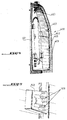
- the figure 1 schematically represents, in perspective and in rear view, a one-piece piece 100 of a headlight or motor vehicle light device, said part consisting in the joining of a mask-type element 101 and different reflector elements 102.
- the piece 100 has, considering the rear view, a straight side with a straight edge 103, and a left side with a flange 104 curved to meet the style and mounting requirements of the motor vehicle manufacturer.
- a plurality, four in this example, of fastening clips 105 are regularly spaced along the entire length of the flange 104.
- a plurality, five in this example, of stresses 106 are offset relative to the fixing clips 105: a horizontal axis on the figure 1 can not simultaneously meet a fastening clip and a stressing tab. The mechanical forces are thus homogeneously distributed over all the edges of the part 100 once the mask assembled to the housing.
- the fastening clips 105 and the stresses 106 are derived from the molding of the mask: they do not constitute here removable elements that would be added to the piece 100 after its manufacture.
- the extension 205 is slid under the flange 104, the clip foot 201 being in direct contact with said flange.
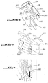
- the figure 4 schematically shows, in perspective and in front view, a housing 400 projector device to be assembled with the single piece 100.
- the housing 400 has, considering the front view shown, a left side with a straight flange 401, and a right side with a curved flange 402.
- each of them is intended to receive and to block one of the fixing clips 105; they are therefore arranged vis-à-vis the fixing clips defined in the mask.
- each retaining element 403 is, in this example, constituted by a first wall 500 and a second wall 501, arranged parallel in a recess 502 of the housing, and having a gap between them substantially equal to a width l of the guiding element 208: the gap between the two walls is ideally slightly smaller, one or two millimeters, at the width 1.
- the walls 500 and 501 each have an insertion face 503, at which is brought one of the clips of fixation at the beginning of a detailed assembly operation later, with a rounded top edge 504 in the shape of a quarter round. This rounded shape facilitates the introduction of the fastening clip 105.
- the definition of the structure of the two-part retaining elements 403 makes it possible to limit the areas of friction with the fastening clip 105, and to limit the insertion force of said clip.
- the retaining elements 403 are derived from the molding of the casing 401: they are here integral with the casing 401 from which they can not be removed.
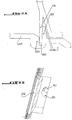
- FIGS. 6 and 7 illustrate according to two different views the establishment of one of the fixing clips 105 in a retaining member 403 according to a clipping operation: the top of the chamfer 204 is brought into contact with the rounded edges 504 of the walls of the element of detention ; the clip foot, which has a certain flexibility and therefore of elasticity properties, then deforms slightly by bending to let the chamfer evolve on the guide walls 500 and 501 in a translational movement 600 corresponding to the direction of introduction fixing clip. The movement is further guided by the passage of the guide element 208 between the two walls, which also ensures a centering of the fastening clip.
- the clip foot returns to its original shape, the locking face 206 of the chamfer being then brought into support, following a folding movement 602, against a face 601 retaining walls, said retaining face being located opposite the insertion faces 503.
- a traction on the fastening clip in an opposite direction in the sense of introduction 600 does not allow to remove the clip out of the retainer.
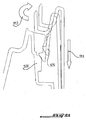
- the tab 106 is made during the molding of the mask. It consists of a generally rectangular shape, of thickness between 1 and 5 millimeters, which protrudes at the surface of the mask, having a free end 800 and a bonded end 801 integral with the surface of the mask.
- the tab 106 of stressing is intended to be embedded in a housing 900, of suitable shape, and formed in the housing.
- the housing 900 is defined between a chamfered volume 901, facilitating the introduction of the tab 106, and a centering tab 902, ensuring the centering of the mask 400 on the housing, while leaving a clearance J between said centering tab and the mask surface to facilitate mounting of the mask due to an inverted "V" shape observed between the stressing tab 106 and the surface of the mask 400.
- a stud 903, visible at the Figure 9-B resulting from the molding of the housing allows the stressing tabs 106 of the mask.
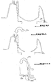
- FIGS. 10-A and 10-B illustrate a first step of assembling the mask on the housing. This assembly is made by buttresses. In this first step, a slight rotation 910 of the mask is carried out in order to allow the introduction of the tabs 106 for stressing in the housing 900 which is reserved for them. The tabs 106 are then pushed into the housing by a translation movement 911, to their final position shown in FIG. figure 12 .
- a rotation movement 912 As illustrated in figure 11 , a rotation movement 912, then a translational movement 913, are also operated at the fastening clips 105 for clipping. As shown in figure 13-A , once the constraint legs are positioned in the housing, it is then possible to perform a slight rotational movement 914 of the mask, in a direction opposite to the rotational movement 912, during this rotation, the tabs 106 are stressed in a force 915, in the housing defined in the housing.
- a mask assembly system on the housing which does not require the use of any fastener or additional material, glue or screw type, or welding operation nor the use of specific tools.
- the clipping system is discrete, being arranged in such a way that it is not visible from outside the vehicle.
Landscapes
- Engineering & Computer Science (AREA)
- General Engineering & Computer Science (AREA)
- Non-Portable Lighting Devices Or Systems Thereof (AREA)
- Lighting Device Outwards From Vehicle And Optical Signal (AREA)
Claims (9)
- Verbindungssystem für eine Maske (101) auf einem Gehäuse (400) eines Scheinwerfers oder Lichts eines Kraftfahrzeugs, eine Maske, zumindest einen Reflektor und ein Gehäuse umfassend, wobei das besagte Verbindungssystem zumindest ein Befestigungsmittel (105) umfasst, das auf der Maske vorhanden ist, und die Maske ein einteiliges Werkstück (100) mit dem besagten zumindest einen Reflektor (102) des Scheinwerfers bildet, wobei die Befestigungsmittel in der Art eines Befestigungsclips ausgeführt sind, und jeder Befestigungsclip einem Rückhalteelement (403) für den besagten Clip zugeordnet ist, das auf dem Gehäuse des Scheinwerfers angeordnet ist, wobei jeder Befestigungsclip einen biegsamen Clipfuß (201) und einen Clipkopf (202) aufweist, der in der Verlängerung des Clipfußes angeordnet ist, und eine Dicke aufweist, die größer ist, als die Dicke des Clipfußes, und mit einer Fase (204) abschließt, wobei jeder Befestigungsclip ein Führungselement (208) aufweist, das im Bereich einer Blockierfläche der Fase vorspringt, und wobei jedes Rückhalteelement eine erste Wand (500) und eine zweite Wand (501) parallel dazu aufweist, die jeweils eine Fläche zum Einführen (503) des Clips aufweisen, um einen Vorgang des Einführens des zugehörigen Clips zu erleichtern, sowie eine Rückhaltfläche (601) für den Clip, zum Blockieren der Fase des Kopfes des zugehörigen Clips.
- Verbindungssystem nach Anspruch 1, dadurch gekennzeichnet, dass die Maske eine von außerhalb des Kraftfahrzeugs nicht sichtbare Rückseite umfasst, wobei sämtliche Befestigungsclips an der besagten Rückseite angeordnet sind.
- Verbindungssystem nach Anspruch 1 oder 2, dadurch gekennzeichnet, dass jeder Befestigungsclip folgendes aufweist:- eine Versteifung (207), die unter dem biegsamen Clipfuß angeordnet ist.
- Verbindungssystem nach irgendeinem der vorherigen Ansprüche, dadurch gekennzeichnet, dass die erste Wand und die zweite Wand eines jeden Rückhalteelements zwischen sich einen Abstand (1) aufweisen, der in etwa gleich der Breite des Führungselements des zugehörigen Clips ist.
- Verbindungssystem nach Anspruch 4, dadurch gekennzeichnet, dass eine Fläche zum Einführen zumindest einer der beiden Wände des Rückhalteelements einen abgerundeten oberen Rand (504) aufweist.
- Verbindungssystem nach einem der vorherigen Ansprüche, dadurch gekennzeichnet, dass die Befestigungsclips mit zumindest einer Spannlasche (106) zusammenwirken, die auf der Maske angeordnet ist, um einen Montagevorgang der Maske auf dem Scheinwerfergehäuse durchzuführen, wobei jede Spannlasche einer Aufnahme (900) zugeordnet ist, die im Scheinwerfergehäuse ausgeführt ist.
- Verbindungssystem nach Anspruch 6, dadurch gekennzeichnet, dass die Befestigungsclips auf einer ersten Seite (104) der Rückseite der Maske angeordnet sind, wobei die Spannlaschen auf einer zweiten Seite (103) der Rückseite der Maske angeordnet sind, die gegenüber der ersten Seite liegt.
- Verbindungssystem nach zumindest einem der vorherigen Ansprüche, dadurch gekennzeichnet, dass die Maske, wenn das Verbindungssystem mehrere Reflektoren umfasst, ein einteiliges Element mit sämtlichen Reflektoren des Scheinwerfers bildet.
- Verbindungssystem nach zumindest einem der vorherigen Ansprüche, dadurch gekennzeichnet, dass eine Scheibe zur Ausgabe der Lichtsignale, die von der Scheinwerferanlage ausgegeben werden, am Gehäuse verschweißt ist.
Applications Claiming Priority (1)
| Application Number | Priority Date | Filing Date | Title |
|---|---|---|---|
| FR0756644A FR2918956B1 (fr) | 2007-07-20 | 2007-07-20 | Systeme d'assemblage d'un masque sur un boitier de projecteur pour vehicule automobile. |
Publications (2)
| Publication Number | Publication Date |
|---|---|
| EP2017527A1 EP2017527A1 (de) | 2009-01-21 |
| EP2017527B1 true EP2017527B1 (de) | 2016-03-16 |
Family
ID=39135311
Family Applications (1)
| Application Number | Title | Priority Date | Filing Date |
|---|---|---|---|
| EP08160073.6A Not-in-force EP2017527B1 (de) | 2007-07-20 | 2008-07-10 | Montagesystem einer Blende auf einem Scheinwerfergehäuse für Kraftfahrzeuge |
Country Status (3)
| Country | Link |
|---|---|
| EP (1) | EP2017527B1 (de) |
| ES (1) | ES2567005T3 (de) |
| FR (1) | FR2918956B1 (de) |
Families Citing this family (2)
| Publication number | Priority date | Publication date | Assignee | Title |
|---|---|---|---|---|
| DE102017103566A1 (de) * | 2017-02-22 | 2018-08-23 | Automotive Lighting Reutlingen Gmbh | Beleuchtungseinrichtung eines Kraftfahrzeugs |
| FR3128004A1 (fr) | 2021-10-13 | 2023-04-14 | Psa Automobiles Sa | Ensemble de masques pour projecteur de véhicules automobiles |
Family Cites Families (5)
| Publication number | Priority date | Publication date | Assignee | Title |
|---|---|---|---|---|
| JP2544681B2 (ja) * | 1990-08-17 | 1996-10-16 | 株式会社小糸製作所 | 自動車用前照灯装置 |
| US6502974B2 (en) * | 1999-02-18 | 2003-01-07 | Lacks Enterprises, Inc. | Integrated flexible lamp assembly |
| DE10258293A1 (de) * | 2002-12-13 | 2004-06-24 | Hella Kg Hueck & Co. | Beleuchtungseinrichtung für Fahrzeuge |
| JP2005050686A (ja) * | 2003-07-29 | 2005-02-24 | Koito Mfg Co Ltd | 車両用灯具 |
| JP2005166359A (ja) * | 2003-12-01 | 2005-06-23 | Koito Mfg Co Ltd | 車両灯具用ランプボディおよび車両用灯具 |
-
2007
- 2007-07-20 FR FR0756644A patent/FR2918956B1/fr not_active Expired - Fee Related
-
2008
- 2008-07-10 ES ES08160073.6T patent/ES2567005T3/es active Active
- 2008-07-10 EP EP08160073.6A patent/EP2017527B1/de not_active Not-in-force
Also Published As
| Publication number | Publication date |
|---|---|
| FR2918956A1 (fr) | 2009-01-23 |
| EP2017527A1 (de) | 2009-01-21 |
| FR2918956B1 (fr) | 2009-10-09 |
| ES2567005T3 (es) | 2016-04-18 |
Similar Documents
| Publication | Publication Date | Title |
|---|---|---|
| EP1985871B1 (de) | Befestigungssystem von zwei Teilen aufeinander | |
| FR3040681A1 (fr) | Equipement automobile pour equiper un ensemble automobile et ensemble automobile comprenant un tel equipement automobile | |
| FR2871131A1 (fr) | Ensemble de carrosserie d'un vehicule automobile | |
| EP2017527B1 (de) | Montagesystem einer Blende auf einem Scheinwerfergehäuse für Kraftfahrzeuge | |
| EP2082923B1 (de) | Anordnung zur Montage einer Zierkappe im Innern eines Scheinwerfergehäuses, die mit Befestigungsmitteln für die Zierkappe auf einem Verschlussglas des Gehäuses ausgestattet ist | |
| EP3112222A1 (de) | Endstück zum montieren auf eine flexible halterung, und scheibenwischer, der ein solches endstück und eine solche flexible halterung umfasst | |
| FR2918632A1 (fr) | Systeme de fixation d'une jupe de feu de vehicule, et procede d'assemblage d'une jupe de feu sur un boitier de feu au moyen d'un tel systeme | |
| WO2012022870A1 (fr) | Dispositif de fixation d'un premier élément sur un second élément, par coopération entre des pattes d'immobilisation et des pattes de fixation | |
| EP0780268B1 (de) | Befestigungssystem für eine Kraftfahrzeuginnenverkleidung | |
| EP2271505B1 (de) | System zum anbringen einer klemme am gehäuse eines schreibinstruments | |
| WO2000033439A1 (fr) | Rotor d'alternateur de vehicule a aimants permanents intercalaires | |
| EP0478403B1 (de) | Befestigungseinrichtung für einen Kühler eines Kraftfahrzeugmotors | |
| EP0984222B1 (de) | Kraftfahrzeugscheinwerfer mit querliegender Lampe und mit verbesserten Lampenmontagemitteln | |
| EP1801331B1 (de) | Griffstütze | |
| EP0685655B1 (de) | Elastische Befestigungsklammer | |
| EP2332783B1 (de) | Ausrüstungsfixierungvorrichtung, mit Immobilisierungmitteln, die sich in den Öffnungen einer Wand Selbstverschließen. | |
| EP1982617A1 (de) | Metallschrank | |
| EP1878927A1 (de) | Teilbare Gussmutter und Gussteil mit einer solchen Mutter | |
| EP0730997A1 (de) | Dekoratives Teil aus Kunststoff | |
| EP1160128A1 (de) | Beleuchtungsvorrichtung oder Anzeigevorrichtung fÜr Kraftfahrzeug mit zwei Teilen durch Schnappverschluss verbunden | |
| WO2024199702A1 (fr) | Element de garnissage d'une armature de siège de véhicule, siège et procédés d'assemblage et de désassemblage associés | |
| EP2235303B1 (de) | Rotor für ein schloss und zugehöriges schloss | |
| FR3104091A1 (fr) | Agencement de garnitures d’habillage destinées à être montées de manière juxtaposée au voisinage d’une portion de joint d’étanchéité | |
| WO2014019773A1 (fr) | Attache élastique, dispositif d'attache et procédé de fabrication correspondant | |
| EP2786028A1 (de) | Fahrzeugelement sowie befestigungsanordnung dafür |
Legal Events
| Date | Code | Title | Description |
|---|---|---|---|
| PUAI | Public reference made under article 153(3) epc to a published international application that has entered the european phase |
Free format text: ORIGINAL CODE: 0009012 |
|
| AK | Designated contracting states |
Kind code of ref document: A1 Designated state(s): AT BE BG CH CY CZ DE DK EE ES FI FR GB GR HR HU IE IS IT LI LT LU LV MC MT NL NO PL PT RO SE SI SK TR |
|
| AX | Request for extension of the european patent |
Extension state: AL BA MK RS |
|
| 17P | Request for examination filed |
Effective date: 20090608 |
|
| 17Q | First examination report despatched |
Effective date: 20090730 |
|
| AKX | Designation fees paid |
Designated state(s): AT BE BG CH CY CZ DE DK EE ES FI FR GB GR HR HU IE IS IT LI LT LU LV MC MT NL NO PL PT RO SE SI SK TR |
|
| GRAP | Despatch of communication of intention to grant a patent |
Free format text: ORIGINAL CODE: EPIDOSNIGR1 |
|
| INTG | Intention to grant announced |
Effective date: 20150928 |
|
| GRAS | Grant fee paid |
Free format text: ORIGINAL CODE: EPIDOSNIGR3 |
|
| GRAA | (expected) grant |
Free format text: ORIGINAL CODE: 0009210 |
|
| AK | Designated contracting states |
Kind code of ref document: B1 Designated state(s): AT BE BG CH CY CZ DE DK EE ES FI FR GB GR HR HU IE IS IT LI LT LU LV MC MT NL NO PL PT RO SE SI SK TR |
|
| REG | Reference to a national code |
Ref country code: GB Ref legal event code: FG4D Free format text: NOT ENGLISH |
|
| REG | Reference to a national code |
Ref country code: CH Ref legal event code: EP |
|
| REG | Reference to a national code |
Ref country code: IE Ref legal event code: FG4D Free format text: LANGUAGE OF EP DOCUMENT: FRENCH |
|
| REG | Reference to a national code |
Ref country code: AT Ref legal event code: REF Ref document number: 781557 Country of ref document: AT Kind code of ref document: T Effective date: 20160415 |
|
| REG | Reference to a national code |
Ref country code: ES Ref legal event code: FG2A Ref document number: 2567005 Country of ref document: ES Kind code of ref document: T3 Effective date: 20160418 |
|
| REG | Reference to a national code |
Ref country code: DE Ref legal event code: R096 Ref document number: 602008042786 Country of ref document: DE |
|
| REG | Reference to a national code |
Ref country code: FR Ref legal event code: PLFP Year of fee payment: 9 |
|
| REG | Reference to a national code |
Ref country code: NL Ref legal event code: MP Effective date: 20160316 |
|
| REG | Reference to a national code |
Ref country code: LT Ref legal event code: MG4D |
|
| PG25 | Lapsed in a contracting state [announced via postgrant information from national office to epo] |
Ref country code: HR Free format text: LAPSE BECAUSE OF FAILURE TO SUBMIT A TRANSLATION OF THE DESCRIPTION OR TO PAY THE FEE WITHIN THE PRESCRIBED TIME-LIMIT Effective date: 20160316 Ref country code: NO Free format text: LAPSE BECAUSE OF FAILURE TO SUBMIT A TRANSLATION OF THE DESCRIPTION OR TO PAY THE FEE WITHIN THE PRESCRIBED TIME-LIMIT Effective date: 20160616 Ref country code: GR Free format text: LAPSE BECAUSE OF FAILURE TO SUBMIT A TRANSLATION OF THE DESCRIPTION OR TO PAY THE FEE WITHIN THE PRESCRIBED TIME-LIMIT Effective date: 20160617 Ref country code: FI Free format text: LAPSE BECAUSE OF FAILURE TO SUBMIT A TRANSLATION OF THE DESCRIPTION OR TO PAY THE FEE WITHIN THE PRESCRIBED TIME-LIMIT Effective date: 20160316 |
|
| PGFP | Annual fee paid to national office [announced via postgrant information from national office to epo] |
Ref country code: GB Payment date: 20160627 Year of fee payment: 9 |
|
| REG | Reference to a national code |
Ref country code: AT Ref legal event code: MK05 Ref document number: 781557 Country of ref document: AT Kind code of ref document: T Effective date: 20160316 |
|
| PG25 | Lapsed in a contracting state [announced via postgrant information from national office to epo] |
Ref country code: LV Free format text: LAPSE BECAUSE OF FAILURE TO SUBMIT A TRANSLATION OF THE DESCRIPTION OR TO PAY THE FEE WITHIN THE PRESCRIBED TIME-LIMIT Effective date: 20160316 Ref country code: SE Free format text: LAPSE BECAUSE OF FAILURE TO SUBMIT A TRANSLATION OF THE DESCRIPTION OR TO PAY THE FEE WITHIN THE PRESCRIBED TIME-LIMIT Effective date: 20160316 Ref country code: LT Free format text: LAPSE BECAUSE OF FAILURE TO SUBMIT A TRANSLATION OF THE DESCRIPTION OR TO PAY THE FEE WITHIN THE PRESCRIBED TIME-LIMIT Effective date: 20160316 Ref country code: NL Free format text: LAPSE BECAUSE OF FAILURE TO SUBMIT A TRANSLATION OF THE DESCRIPTION OR TO PAY THE FEE WITHIN THE PRESCRIBED TIME-LIMIT Effective date: 20160316 |
|
| REG | Reference to a national code |
Ref country code: DE Ref legal event code: R084 Ref document number: 602008042786 Country of ref document: DE |
|
| REG | Reference to a national code |
Ref country code: ES Ref legal event code: GC2A Effective date: 20161014 |
|
| PG25 | Lapsed in a contracting state [announced via postgrant information from national office to epo] |
Ref country code: PL Free format text: LAPSE BECAUSE OF FAILURE TO SUBMIT A TRANSLATION OF THE DESCRIPTION OR TO PAY THE FEE WITHIN THE PRESCRIBED TIME-LIMIT Effective date: 20160316 Ref country code: EE Free format text: LAPSE BECAUSE OF FAILURE TO SUBMIT A TRANSLATION OF THE DESCRIPTION OR TO PAY THE FEE WITHIN THE PRESCRIBED TIME-LIMIT Effective date: 20160316 Ref country code: IS Free format text: LAPSE BECAUSE OF FAILURE TO SUBMIT A TRANSLATION OF THE DESCRIPTION OR TO PAY THE FEE WITHIN THE PRESCRIBED TIME-LIMIT Effective date: 20160716 |
|
| REG | Reference to a national code |
Ref country code: GB Ref legal event code: 746 Effective date: 20161011 |
|
| PG25 | Lapsed in a contracting state [announced via postgrant information from national office to epo] |
Ref country code: AT Free format text: LAPSE BECAUSE OF FAILURE TO SUBMIT A TRANSLATION OF THE DESCRIPTION OR TO PAY THE FEE WITHIN THE PRESCRIBED TIME-LIMIT Effective date: 20160316 Ref country code: RO Free format text: LAPSE BECAUSE OF FAILURE TO SUBMIT A TRANSLATION OF THE DESCRIPTION OR TO PAY THE FEE WITHIN THE PRESCRIBED TIME-LIMIT Effective date: 20160316 Ref country code: PT Free format text: LAPSE BECAUSE OF FAILURE TO SUBMIT A TRANSLATION OF THE DESCRIPTION OR TO PAY THE FEE WITHIN THE PRESCRIBED TIME-LIMIT Effective date: 20160718 Ref country code: SK Free format text: LAPSE BECAUSE OF FAILURE TO SUBMIT A TRANSLATION OF THE DESCRIPTION OR TO PAY THE FEE WITHIN THE PRESCRIBED TIME-LIMIT Effective date: 20160316 Ref country code: CZ Free format text: LAPSE BECAUSE OF FAILURE TO SUBMIT A TRANSLATION OF THE DESCRIPTION OR TO PAY THE FEE WITHIN THE PRESCRIBED TIME-LIMIT Effective date: 20160316 |
|
| REG | Reference to a national code |
Ref country code: DE Ref legal event code: R097 Ref document number: 602008042786 Country of ref document: DE |
|
| PG25 | Lapsed in a contracting state [announced via postgrant information from national office to epo] |
Ref country code: IT Free format text: LAPSE BECAUSE OF FAILURE TO SUBMIT A TRANSLATION OF THE DESCRIPTION OR TO PAY THE FEE WITHIN THE PRESCRIBED TIME-LIMIT Effective date: 20160316 Ref country code: BE Free format text: LAPSE BECAUSE OF NON-PAYMENT OF DUE FEES Effective date: 20160731 |
|
| PLBE | No opposition filed within time limit |
Free format text: ORIGINAL CODE: 0009261 |
|
| STAA | Information on the status of an ep patent application or granted ep patent |
Free format text: STATUS: NO OPPOSITION FILED WITHIN TIME LIMIT |
|
| PG25 | Lapsed in a contracting state [announced via postgrant information from national office to epo] |
Ref country code: DK Free format text: LAPSE BECAUSE OF FAILURE TO SUBMIT A TRANSLATION OF THE DESCRIPTION OR TO PAY THE FEE WITHIN THE PRESCRIBED TIME-LIMIT Effective date: 20160316 |
|
| 26N | No opposition filed |
Effective date: 20161219 |
|
| PG25 | Lapsed in a contracting state [announced via postgrant information from national office to epo] |
Ref country code: BG Free format text: LAPSE BECAUSE OF FAILURE TO SUBMIT A TRANSLATION OF THE DESCRIPTION OR TO PAY THE FEE WITHIN THE PRESCRIBED TIME-LIMIT Effective date: 20160616 |
|
| REG | Reference to a national code |
Ref country code: CH Ref legal event code: PL |
|
| PG25 | Lapsed in a contracting state [announced via postgrant information from national office to epo] |
Ref country code: MC Free format text: LAPSE BECAUSE OF FAILURE TO SUBMIT A TRANSLATION OF THE DESCRIPTION OR TO PAY THE FEE WITHIN THE PRESCRIBED TIME-LIMIT Effective date: 20160316 |
|
| PG25 | Lapsed in a contracting state [announced via postgrant information from national office to epo] |
Ref country code: LI Free format text: LAPSE BECAUSE OF NON-PAYMENT OF DUE FEES Effective date: 20160731 Ref country code: CH Free format text: LAPSE BECAUSE OF NON-PAYMENT OF DUE FEES Effective date: 20160731 |
|
| REG | Reference to a national code |
Ref country code: IE Ref legal event code: MM4A |
|
| PG25 | Lapsed in a contracting state [announced via postgrant information from national office to epo] |
Ref country code: SI Free format text: LAPSE BECAUSE OF FAILURE TO SUBMIT A TRANSLATION OF THE DESCRIPTION OR TO PAY THE FEE WITHIN THE PRESCRIBED TIME-LIMIT Effective date: 20160316 |
|
| REG | Reference to a national code |
Ref country code: FR Ref legal event code: PLFP Year of fee payment: 10 |
|
| PG25 | Lapsed in a contracting state [announced via postgrant information from national office to epo] |
Ref country code: IE Free format text: LAPSE BECAUSE OF NON-PAYMENT OF DUE FEES Effective date: 20160710 |
|
| PG25 | Lapsed in a contracting state [announced via postgrant information from national office to epo] |
Ref country code: LU Free format text: LAPSE BECAUSE OF NON-PAYMENT OF DUE FEES Effective date: 20160710 |
|
| GBPC | Gb: european patent ceased through non-payment of renewal fee |
Effective date: 20170710 |
|
| PG25 | Lapsed in a contracting state [announced via postgrant information from national office to epo] |
Ref country code: GB Free format text: LAPSE BECAUSE OF NON-PAYMENT OF DUE FEES Effective date: 20170710 |
|
| PG25 | Lapsed in a contracting state [announced via postgrant information from national office to epo] |
Ref country code: HU Free format text: LAPSE BECAUSE OF FAILURE TO SUBMIT A TRANSLATION OF THE DESCRIPTION OR TO PAY THE FEE WITHIN THE PRESCRIBED TIME-LIMIT; INVALID AB INITIO Effective date: 20080710 Ref country code: CY Free format text: LAPSE BECAUSE OF FAILURE TO SUBMIT A TRANSLATION OF THE DESCRIPTION OR TO PAY THE FEE WITHIN THE PRESCRIBED TIME-LIMIT Effective date: 20160316 |
|
| REG | Reference to a national code |
Ref country code: FR Ref legal event code: PLFP Year of fee payment: 11 |
|
| PG25 | Lapsed in a contracting state [announced via postgrant information from national office to epo] |
Ref country code: TR Free format text: LAPSE BECAUSE OF FAILURE TO SUBMIT A TRANSLATION OF THE DESCRIPTION OR TO PAY THE FEE WITHIN THE PRESCRIBED TIME-LIMIT Effective date: 20160316 Ref country code: MT Free format text: LAPSE BECAUSE OF FAILURE TO SUBMIT A TRANSLATION OF THE DESCRIPTION OR TO PAY THE FEE WITHIN THE PRESCRIBED TIME-LIMIT Effective date: 20160316 |
|
| REG | Reference to a national code |
Ref country code: FR Ref legal event code: CA Effective date: 20180312 Ref country code: FR Ref legal event code: CD Owner name: PEUGEOT CITROEN AUTOMOBILES SA, FR Effective date: 20180312 |
|
| PGFP | Annual fee paid to national office [announced via postgrant information from national office to epo] |
Ref country code: ES Payment date: 20220801 Year of fee payment: 15 Ref country code: DE Payment date: 20220621 Year of fee payment: 15 |
|
| REG | Reference to a national code |
Ref country code: DE Ref legal event code: R119 Ref document number: 602008042786 Country of ref document: DE |
|
| PG25 | Lapsed in a contracting state [announced via postgrant information from national office to epo] |
Ref country code: DE Free format text: LAPSE BECAUSE OF NON-PAYMENT OF DUE FEES Effective date: 20240201 |
|
| PGFP | Annual fee paid to national office [announced via postgrant information from national office to epo] |
Ref country code: FR Payment date: 20240619 Year of fee payment: 17 |
|
| REG | Reference to a national code |
Ref country code: ES Ref legal event code: FD2A Effective date: 20240828 |
|
| PG25 | Lapsed in a contracting state [announced via postgrant information from national office to epo] |
Ref country code: ES Free format text: LAPSE BECAUSE OF NON-PAYMENT OF DUE FEES Effective date: 20230711 |
|
| PG25 | Lapsed in a contracting state [announced via postgrant information from national office to epo] |
Ref country code: ES Free format text: LAPSE BECAUSE OF NON-PAYMENT OF DUE FEES Effective date: 20230711 |
|
| PG25 | Lapsed in a contracting state [announced via postgrant information from national office to epo] |
Ref country code: FR Free format text: LAPSE BECAUSE OF NON-PAYMENT OF DUE FEES Effective date: 20250731 |