EP2017501A2 - Appareil de contrôle de transmission automatique - Google Patents
Appareil de contrôle de transmission automatique Download PDFInfo
- Publication number
- EP2017501A2 EP2017501A2 EP08010299A EP08010299A EP2017501A2 EP 2017501 A2 EP2017501 A2 EP 2017501A2 EP 08010299 A EP08010299 A EP 08010299A EP 08010299 A EP08010299 A EP 08010299A EP 2017501 A2 EP2017501 A2 EP 2017501A2
- Authority
- EP
- European Patent Office
- Prior art keywords
- neutral control
- fluid pressure
- brake fluid
- brake
- automatic transmission
- Prior art date
- Legal status (The legal status is an assumption and is not a legal conclusion. Google has not performed a legal analysis and makes no representation as to the accuracy of the status listed.)
- Granted
Links
- 230000005540 biological transmission Effects 0.000 title claims abstract description 56
- 230000007935 neutral effect Effects 0.000 claims abstract description 170
- 239000012530 fluid Substances 0.000 claims abstract description 47
- 230000000994 depressogenic effect Effects 0.000 claims abstract description 6
- 238000000034 method Methods 0.000 claims description 3
- 239000002826 coolant Substances 0.000 description 8
- 230000006870 function Effects 0.000 description 5
- 230000007423 decrease Effects 0.000 description 4
- 230000000881 depressing effect Effects 0.000 description 3
- 230000000694 effects Effects 0.000 description 3
- 238000004891 communication Methods 0.000 description 2
- 238000005516 engineering process Methods 0.000 description 2
- 239000003112 inhibitor Substances 0.000 description 2
- 230000004044 response Effects 0.000 description 2
- 230000035939 shock Effects 0.000 description 2
- 230000001133 acceleration Effects 0.000 description 1
- 239000008186 active pharmaceutical agent Substances 0.000 description 1
- 230000000052 comparative effect Effects 0.000 description 1
- 239000000470 constituent Substances 0.000 description 1
- 238000001514 detection method Methods 0.000 description 1
- 238000010586 diagram Methods 0.000 description 1
- 230000009977 dual effect Effects 0.000 description 1
- 239000000446 fuel Substances 0.000 description 1
- 230000005484 gravity Effects 0.000 description 1
- 230000007246 mechanism Effects 0.000 description 1
- 238000012986 modification Methods 0.000 description 1
- 230000004048 modification Effects 0.000 description 1
- 230000002265 prevention Effects 0.000 description 1
Images

Classifications
-
- F—MECHANICAL ENGINEERING; LIGHTING; HEATING; WEAPONS; BLASTING
- F16—ENGINEERING ELEMENTS AND UNITS; GENERAL MEASURES FOR PRODUCING AND MAINTAINING EFFECTIVE FUNCTIONING OF MACHINES OR INSTALLATIONS; THERMAL INSULATION IN GENERAL
- F16H—GEARING
- F16H61/00—Control functions within control units of change-speed- or reversing-gearings for conveying rotary motion ; Control of exclusively fluid gearing, friction gearing, gearings with endless flexible members or other particular types of gearing
- F16H61/20—Preventing gear creeping ; Transmission control during standstill, e.g. hill hold control
-
- B—PERFORMING OPERATIONS; TRANSPORTING
- B60—VEHICLES IN GENERAL
- B60W—CONJOINT CONTROL OF VEHICLE SUB-UNITS OF DIFFERENT TYPE OR DIFFERENT FUNCTION; CONTROL SYSTEMS SPECIALLY ADAPTED FOR HYBRID VEHICLES; ROAD VEHICLE DRIVE CONTROL SYSTEMS FOR PURPOSES NOT RELATED TO THE CONTROL OF A PARTICULAR SUB-UNIT
- B60W30/00—Purposes of road vehicle drive control systems not related to the control of a particular sub-unit, e.g. of systems using conjoint control of vehicle sub-units
- B60W30/18—Propelling the vehicle
- B60W30/18009—Propelling the vehicle related to particular drive situations
- B60W30/18063—Creeping
-
- F—MECHANICAL ENGINEERING; LIGHTING; HEATING; WEAPONS; BLASTING
- F16—ENGINEERING ELEMENTS AND UNITS; GENERAL MEASURES FOR PRODUCING AND MAINTAINING EFFECTIVE FUNCTIONING OF MACHINES OR INSTALLATIONS; THERMAL INSULATION IN GENERAL
- F16H—GEARING
- F16H61/00—Control functions within control units of change-speed- or reversing-gearings for conveying rotary motion ; Control of exclusively fluid gearing, friction gearing, gearings with endless flexible members or other particular types of gearing
- F16H61/20—Preventing gear creeping ; Transmission control during standstill, e.g. hill hold control
- F16H2061/207—Preventing gear creeping ; Transmission control during standstill, e.g. hill hold control by neutral control
-
- F—MECHANICAL ENGINEERING; LIGHTING; HEATING; WEAPONS; BLASTING
- F16—ENGINEERING ELEMENTS AND UNITS; GENERAL MEASURES FOR PRODUCING AND MAINTAINING EFFECTIVE FUNCTIONING OF MACHINES OR INSTALLATIONS; THERMAL INSULATION IN GENERAL
- F16H—GEARING
- F16H2312/00—Driving activities
- F16H2312/06—Creeping
-
- F—MECHANICAL ENGINEERING; LIGHTING; HEATING; WEAPONS; BLASTING
- F16—ENGINEERING ELEMENTS AND UNITS; GENERAL MEASURES FOR PRODUCING AND MAINTAINING EFFECTIVE FUNCTIONING OF MACHINES OR INSTALLATIONS; THERMAL INSULATION IN GENERAL
- F16H—GEARING
- F16H59/00—Control inputs to control units of change-speed- or reversing-gearings for conveying rotary motion
- F16H59/50—Inputs being a function of the status of the machine, e.g. position of doors or safety belts
- F16H59/54—Inputs being a function of the status of the machine, e.g. position of doors or safety belts dependent on signals from the brakes, e.g. parking brakes
Definitions
- the present invention generally relates to an automatic transmission control apparatus equipped with a neutral control configured to prohibit transmission of a creep torque to a drive wheel when a prescribed condition is satisfied.
- a prescribed amount of torque (called "creep torque") is produced when an accelerator pedal depression amount is zero while a traveling range, e.g., Drive or Reverse, is selected.
- a traveling range e.g., Drive or Reverse
- a neutral control is executed whereby a holding element is released and the automatic transmission is put into a neutral state in order to avoid imposing an unnecessary load on the engine.
- a known method of determining when to execute and end the neutral control is use a brake switch signal. More specifically, the neutral control is started when a brake switch outputs an on-signal and ended when the brake switch outputs an off-signal.
- the brake switch Since the brake switch outputs the on-signal in response to even a slight amount of brake pedal depression, there are times when the neutral control is executed even though the driver does not intend to stop. A feasible way of avoiding this problem is to set the on and off threshold values of the brake switch to higher values. However, since the brake switch serves as the signal for turning the brake lamps on and off, increasing the threshold values makes the brake lamps illuminate less readily and poses a problem from a safety standpoint. In short, it is not possible to accurately detect the driver's brake depression amount (intention to stop) based on a signal from a brake switch.
- Japanese Laid-Open Patent Publication No. 5-87236 discloses a technology whereby the start timing and end timing of a neutral control is determined based on a brake fluid pressure of a brake pedal instead of a brake switch.
- a driver's intent to stop is determined based on an operation amount (brake fluid pressure) of a brake pedal in connection with executing a creep prevention control and a neutral control.
- a different threshold value of the operation amount of the brake pedal is used for starting the neutral control than for ending the neutral control.
- a threshold value A for the neutral control is set to a larger value than a threshold value B for ending the neutral control (threshold value A > threshold value B).
- a common driving technique is to utilize creep torque by repeatedly depressing and releasing the brake pedal so as to adjust the amount of creep torque transferred to the road surface.
- the brake-fluid pressure falls below the threshold value B and the neutral control ends.
- the starting clutch connects and the vehicle changes from a neutral state to a creep state, thus resulting in a drive force being obtained.
- the object of the present invention is provide an automatic transmission control apparatus configured to suppress hunting with respect to starting and ending a neutral control and make it possible for a driver to fine adjust the vehicle speed when driving using creep torque.
- an automatic transmission control apparatus basically comprises a brake switch, a brake fluid pressure detecting section, a range position detecting section, a neutral control section and a prohibiting section.
- the brake switch is configured to output an on-signal when a brake pedal is depressed and otherwise output an off-signal.
- the brake fluid pressure detecting section is configured to detect a brake fluid pressure corresponding to a brake pedal depression force.
- the range position detecting section is configured to detect if a traveling range of an automatic transmission is selected.
- the neutral control section is configured to start a neutral control that puts the automatic transmission into a neutral state when the brake fluid pressure detected by the brake fluid detecting section exceeds a start threshold value while the range position detecting section detects that the traveling range is selected, and to end the neutral control when the brake fluid pressure falls below an end threshold value while the neutral control is being executed, with the start and end threshold values being set to values that are higher than the brake fluid pressure occurring when the brake switch starts outputting the on-signal.
- the prohibiting section is configured to prohibit the neutral control from being subsequently started again, after the neutral control has been started by the neutral control section, regardless of the brake fluid pressure detected by the brake fluid pressure detecting section until the brake switch outputs the off-signal.
- FIG. 1 is a full schematic system diagram of a vehicle equipped with an automatic transmission control apparatus in accordance with one embodiment
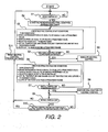
- Figure 2 is a flowchart showing a control executed by a neutral control section in the illustrated embodiment of Figure 1 ;
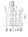
- Figure 3 is a time chart illustrating a situation in which the neutral control starts due to a driver decelerating while driving in congestion and, afterwards, the driver fine adjusts the vehicle speed by adjusting the depression force exerted against the brake pedal BP while maintaining a depressed state (i.e., not releasing the brake pedal BP).
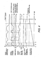
- Figure 4 is a time chart illustrating a situation in which the neutral control starts due to the driver decelerating while driving in congestion and, afterwards, the driver fine adjusts the vehicle speed by adjusting the depression force exerted against the brake pedal BP while maintaining a depressed state (i.e., not releasing the brake pedal BP). Then, still afterwards, the driver depresses the brake pedal BP again and stops the vehicle.
- a vehicle is illustrated that is equipped with an automatic transmission control apparatus in accordance with one embodiment.
- the vehicle presented in the illustrated embodiment is a rear wheel drive vehicle, it is acceptable for the vehicle to be a front wheel drive vehicle or a four wheel drive vehicle.
- the vehicle in the illustrated embodiment is equipped with an engine E, a torque converter TC and an automatic transmission AT.
- a drive force outputted from the engine E is transmitted through the torque converter TC to an input shaft IN of the automatic transmission AT.
- a starting clutch CL is provided inside the automatic transmission such that a drive force transmitted through the starting clutch CL is transmitted from an output shaft OUT to a differential DF.
- the differential DF transfers the drive force to a pair of drives shafts DS of the left and right rear wheels RR and RL such that the drive force is transmitted to the rear wheels RR and RL.
- the automatic transmission AT sets a gear ratio in accordance with a traveling state, thereby increasing or reducing the rotational speed of the output shaft OUT with respect to the rotational speed of the input shaft IN. If the automatic transmission AT is a standard step-type automatic transmission (not a continuously variable transmission), then one of the holding members used to achieve first gear is the starting clutch CL. If the automatic transmission AT is a continuously variable transmission, then a frictional element such as a forward clutch or a reverse brake provided in a forward/reverse switching mechanism will serve as the starting clutch CL.
- a disc rotor DR is attached to each of the front wheels FR and FL such that it can rotate integrally therewith.
- a disc rotor DR is attached to each of the rear wheels RR and RL such that it can rotate integrally therewith.
- a brake caliper configured to press a brake pad against the disc rotor DR so as to impart a frictional braking force is mounted in the vicinity of each of the disc rotors DR.
- a wheel cylinder W/C is provided inside each brake caliper and serves to determine the force with which the brake pad is pressed against the disc rotor DR (i.e., determine the frictional brake force).
- Each of the wheel cylinders W/C is connected to a master cylinder MC via a brake fluid tube.
- the master cylinder MC is an element that generates a brake pressure corresponding to a brake pedal depression force resulting when a driver operates a brake pedal BP is a so-called tandem master cylinder.
- the brake fluid tubing has an X-configuration (diagonally split) such that one hydraulic circuit of the master cylinder is connected to the right front wheel FR and the left rear wheel RL and the other hydraulic circuit of the master cylinder is connected to the left front wheel FL and the right rear wheel RR.
- a master cylinder pressure sensor MC/SEN detects a master cylinder pressure is provided in the master cylinder hydraulic circuit that is connected to the left front wheel FL and the right rear wheel RR.
- the brake switch BS is provided on the brake pedal BP. In addition to being used for a neutral control of the automatic transmission, the brake switch BS serves as a trigger for illuminating a brake lamp that serves to indicate that the driver is depressing the brake pedal.
- An automatic transmission controller ATCU is provided to determine which gear the automatic transmission AT will be shifted to, based on various input data and outputs a control command signal to actuators in order to achieve the determined gear (or gear ratio). Also, a neutral control section 5 is provided inside the automatic transmission controller ATCU. The neutral control section 5 controls the connection and release of the starting clutch CL based on various input data. More specifically, the neutral control section 5 releases the starting clutch CL when a neutral control is executed and connects the starting clutch CL when the neutral control is not executed.
- the neutral control is prohibited from being started again until the brake switch BS outputs the off-signal.
- the vehicle is either in a state in which the neutral control is in progress (being executed) or a state in which the neutral control has been ended. If the neutral control has been ended but the brake switch BS is outputting the on-signal, then it can be assumed that the driver is fine adjusting the vehicle speed by operating the brake pedal.
- the automatic transmission controller ATCU preferably includes a microcomputer with a neutral control program that controls the automatic transmission AT as discussed below.
- the automatic transmission controller ATCU 20 also includes other conventional components such as an input interface circuit, an output interface circuit, and storage devices such as a ROM (Read Only Memory) device and a RAM (Random Access Memory) device as needed and/or desires. It will be apparent to those skilled in the art from this disclosure that the precise structure and algorithms for the automatic transmission controller ATCU can be any combination of hardware and software that will carry out the functions of the automatic transmission controller ATCU as discussed herein.
- the signals fed to the automatic transmission controller ATCU include an on-off signal of the brake switch BS, a master cylinder pressure signal from the master cylinder pressure sensor MC/SEN, a range position signal of an inhibitor switch ISW indicating a shift lever position selected by a driver, a vehicle speed signal from a vehicle speed sensor 1, a slope angle signal from a slope angle sensor 2 that detects a grade of a road surface on which the vehicle is traveling, an oil temperature signal from an ATF oil temperature sensor 3 that detects an oil temperature inside the automatic transmission AT, and a coolant temperature signal from an engine coolant temperature sensor 4 that detects a coolant temperature of the engine E.
- the inhibitor switch ISW outputs signals indicating the forward traveling range positions (D, L, 1, 2, etc.), the reverse traveling range position (R), the neutral range position (N), and the parking range position (P).
- the term "traveling range” refers to both the forward traveling ranges and the reverse traveling range.
- FIG. 2 is a flowchart showing the control operations executed by the neutral control section 5.
- step S1 the neutral control section 5 determines if the brake switch BS is "on". If so, the neutral control section 5 proceeds to step S2. Otherwise, the neutral control section 5 repeats step S 1.
- step S2 the neutral control section starts incrementing a neutral control prohibition timer.
- the incrementing of the neutral control prohibition timer is not related to the control cycle time or flow of the flowchart and is executed independently.
- step S3 the neutral control section 5 determines if some prescribed neutral control start conditions are satisfied. All of the conditions listed below must be satisfied in order to start the neutral control.
- Condition 1 The brake depression force is equal to or higher than a prescribed value (the master cylinder pressure is equal to or above a start threshold value).
- Condition 2 The vehicle speed is equal to or below a prescribed value.
- the selected range is a traveling range.
- Condition 4 The ATF oil temperature and the engine coolant temperature are within a prescribed range.
- Condition 5 The slope of the road is within a prescribed range.
- Condition 1 Since it is necessary for the driver to be indicating an intent to stop, the start threshold value of Condition 1 is set to a value higher than the value at which the brake switch BS starts outputting the on-signal.
- Condition 2 is included because an engine braking effect cannot be obtained if the automatic transmission is put into a neutral state while the vehicle speed is high.
- Condition 3 is included because the transmission is inherently in a neutral state in ranges other than the traveling ranges.
- Condition 4 is included because an appropriate viscosity cannot be obtained if the ATF oil temperature is not within a prescribed range and the connection and release control of the neutral control cannot be executed precisely if the viscosity is not appropriate. If the engine coolant temperature is not within a prescribed range, then it is necessary to lower the temperature of the coolant and it is better to lower the engine rotational speed in order to lower the coolant temperature. The engine rotational speed will decrease more readily if a load is acting on the engine than if the transmission is in a neutral state.
- Condition 5 is included because there are situations in which the vehicle will carry an acceleration component resulting from the force of gravity if the road slope is not within a prescribed range and, in such a situation, the vehicle could move in the direction of the slope if the transmission is put into a neutral state while the master cylinder pressure is insufficient.
- step S4 the neutral control section 5 determines if all of the neutral control start conditions were found to be satisfied. Ifso, the neutral control section 5 proceeds to steps S5 and S6. Otherwise, the neutral control section 5 repeats step S3.
- step S5 the neutral control section 5 executes the neutral control.
- the neutral control is a control that serves to release the starting clutch CL while a traveling range is selected.
- the control is configured to release the starting clutch CL gradually because the driver will likely feel a sudden loss of torque if the clutch CL is released abruptly.
- the neutral control is executed as appropriate based on a control logic that is separate from the control loop shown in the flowchart until the starting clutch CL is completely released. Then, after the starting clutch CL is completely released, the neutral control is ended in an appropriate fashion.
- step S6 the neutral control section 5 determines if some prescribed neutral control end conditions are satisfied.
- the neutral control section determines that the neutral control should be ended if any of the conditions listed below is satisfied.
- the brake depression force is equal to or below a prescribed value (the master cylinder pressure is equal to or below an end threshold value).
- Condition 7 The vehicle speed is equal to or above a prescribed value.
- Condition 8 The selected range is not a traveling range.
- Condition 9 The ATF oil temperature and the engine coolant temperature are outside a prescribed range.
- Condition 6 Since it is necessary for the driver to be cancelling an intent to stop, the end threshold value of Condition 6 is set to a value smaller than the start threshold value and higher than the value at which the brake switch BS starts outputting the on-signal. As a result, control hunting is prevented.
- Conditions 7 to 10 are included for the opposite reasons as conditions 2 to 5 and explanations thereof are omitted here.
- step S7 the neutral control section 5 determines if a neutral control end conditions was found to be satisfied. If so, the neutral control section 5 proceeds to steps S8 and S9. Otherwise, the neutral control section 5 repeats step S6.
- step S8 the neutral control section 5 executes a neutral control end control.
- the neutral control end control is a control that serves to reconnect the released starting clutch CL.
- the end control is configured to connect the starting clutch CL gradually so as to suppress connection shock and torque fluctuations imparted to the drive wheels as a result of connecting the starting clutch CL.
- the end control is executed as appropriate based on a control logic that is separate from the control loop shown in the flowchart until the starting clutch CL is completely connected. Then, after the starting clutch CL is completely connected, the neutral control is ended in an appropriate fashion.
- step S9 the neutral control section 5 determines if the brake switch BS is outputting the on-signal. If so, then the neutral control section 5 proceeds to step 10. Otherwise, the neutral control section 5 proceeds to step S 11.
- step S 10 the neutral control section determines if the value of the neutral control prohibition timer is larger than a preset neutral control prohibition cancellation time. If so, then the neutral control section 5 proceeds to step S 11. Otherwise, the neutral control section 5 returns to step S9.
- Steps S9 and S10 combine to form a prohibiting section that prohibits the neutral control from being started.
- step S11 the neutral control section 5 resets the neutral control prohibition timer and returns to step S1 so as to repeat the control loop as a whole.
- Figure 3 is a time chart for a situation in which the neutral control starts due to the driver decelerating while driving in congestion and, afterwards, the driver fine adjusts the vehicle speed by adjusting the depression force exerted against the brake pedal BP while maintaining a depressed state (i.e., not releasing the brake pedal BP). It is assumed that all of Conditions 2 to 5 are satisfied and all of the conditions 7 to 10 are not satisfied.
- the driver starts to depress the brake pedal BP and the brake-switch BS issues the on-signal.
- the neutral control prohibition timer starts incrementing.
- the brake switch BS does not operate based on the master cylinder pressure, it is clear from the figure that output of the on-signal starts at a very low master cylinder pressure value.
- the driver depresses the brake pedal BP more strongly in order to further reduce the vehicle speed and the master cylinder pressure increases beyond the start threshold value.
- the neutral control start conditions are satisfied and the neutral control is started.
- step S9 repeats steps S9 and S10 until the brake switch BS outputs the off-switch or until the neutral control prohibition timer exceeds the prohibition cancellation time in step S10. In other words, determination of whether the neutral control should be started or ended is completely prohibited. Consequently, the period during which the steps S9 and S10 are repeated is equivalent to a neutral control start determination prohibition flag being set to 1.
- the neutral control is not executed even if the master cylinder pressure changes and exceeds the start threshold value or falls below the end threshold value.
- the dotted-line curve shown in the neutral control start/end section of Figure 3 is a time chart illustrating a comparative example. If the neutral control is executed based solely on the relationship between the master cylinder pressure and the start and end threshold values, then neutral control will be executed frequently and the vehicle speed will decrease excessively due to the neutral state, as illustrated with the dotted-line curve of the vehicle speed. As a result, it will be difficult to fine adjust the vehicle speed and the drivability of the vehicle will be degraded. Conversely, with a control according to the illustrated embodiment, the vehicle speed does not decrease excessively and the vehicle speed can be fine adjusted easily.
- the driver releases the brake pedal BP and attempts to accelerate. Since the brake switch outputs the off-signal in step S9, the neutral control start determination prohibition flat is reset to 0. As a result, when the driver depresses the brake pedal BP again, the neutral control section 5 can execute the neutral control start determination again.
- Figure 4 is a time chart for a situation in which the neutral control starts due to the driver decelerating while driving in congestion and, afterwards, the driver fine adjusts the vehicle speed by adjusting the depression force exerted against the brake pedal BP while maintaining a depressed state (i.e., not releasing the brake pedal BP). Then, still afterwards, the driver depresses the brake pedal BP again and stops the vehicle. Explanations of the portions from the time t1 to the time t3 are omitted because those portions are the same as in Figure 3 .
- the neutral control section 5 At a time t5, the value of the neutral control prohibition timer (which started incrementing at the time tl) surpasses a preset prohibition cancellation time and the neutral control section 5 determines that the driver clearly intends to completely stop the vehicle. Therefore, the neutral control start determination prohibition flag is reset to 0. In other words, the neutral control section 5 starts determining if the neutral control should be started. At this point in time, Condition 1 is satisfied because the driver is depressing the brake pedal BP with such that the master cylinder pressure is higher than the start threshold value. Therefore, the neutral control starts.
- the neutral control start determination can be resumed when the neutral control prohibition timer reaches a value indicating that the prohibition cancellation time has elapsed. As a result, excessive limitation of the neutral control can be avoided.
- the present invention is explained herein based on the illustrated embodiment, the invention is not limited to specific constituent features of the embodiment described above.
- the various sensor signals are fed to the automatic transmission controller ATCU, it is acceptable to connect the automatic transmission controller ATCU to a brake controller or the like with a CAN communication line and feed various sensor signals that are received by the brake controller to the automatic transmission controller ATCU through the CAN communication line.
- the brake pedal depression force exerted by the driver is detected by detecting the master cylinder pressure
- a brake switch signal is used to cancel the prohibition of the neutral control start determination
- the invention is not limited to using a brake switch.
- it is acceptable to cancel the prohibition when a value corresponding to the brake pedal depression force exerted by the driver falls below a prescribed value that is smaller than the start threshold value or the end threshold value.
- detect as used herein to describe an operation or function carried out by a component, a section, a device or the like includes a component, a section, a device or the like that does not require physical detection, but rather includes determining, measuring, modeling, predicting or computing or the like to carry out the operation or function.
- Configured as used herein to describe a component, section or part of a device includes hardware and/or software that is constructed and/or programmed to carry out the desired function.
- degree such as “substantially”, “about” and “approximately” as used herein mean a reasonable amount of deviation of the modified term such that the end result is not significantly changed.
Landscapes
- Engineering & Computer Science (AREA)
- Mechanical Engineering (AREA)
- General Engineering & Computer Science (AREA)
- Automation & Control Theory (AREA)
- Transportation (AREA)
- Control Of Transmission Device (AREA)
Applications Claiming Priority (1)
| Application Number | Priority Date | Filing Date | Title |
|---|---|---|---|
| JP2007187769A JP4455622B2 (ja) | 2007-07-19 | 2007-07-19 | 自動変速機の制御装置 |
Publications (3)
| Publication Number | Publication Date |
|---|---|
| EP2017501A2 true EP2017501A2 (fr) | 2009-01-21 |
| EP2017501A3 EP2017501A3 (fr) | 2011-08-03 |
| EP2017501B1 EP2017501B1 (fr) | 2012-08-15 |
Family
ID=39832034
Family Applications (1)
| Application Number | Title | Priority Date | Filing Date |
|---|---|---|---|
| EP08010299A Ceased EP2017501B1 (fr) | 2007-07-19 | 2008-06-05 | Appareil de contrôle de transmission automatique et la méthode correspondante |
Country Status (3)
| Country | Link |
|---|---|
| US (1) | US7861838B2 (fr) |
| EP (1) | EP2017501B1 (fr) |
| JP (1) | JP4455622B2 (fr) |
Cited By (1)
| Publication number | Priority date | Publication date | Assignee | Title |
|---|---|---|---|---|
| US10724631B2 (en) * | 2016-07-25 | 2020-07-28 | Guangzhou Automobile Group Co., Ltd. | Method for controlling neutral gear of automatic transmission |
Families Citing this family (11)
| Publication number | Priority date | Publication date | Assignee | Title |
|---|---|---|---|---|
| DE102005027098A1 (de) * | 2005-06-11 | 2006-12-14 | Zf Friedrichshafen Ag | Verfahren zum Schalten eines Kraftfahrzeug-Automatikgetriebes mit hydrodynamischem Drehmomentwandler beim Anhalten des Fahrzeuges |
| JP2008309267A (ja) * | 2007-06-15 | 2008-12-25 | Jatco Ltd | 自動変速機の制御装置 |
| JP2008309266A (ja) * | 2007-06-15 | 2008-12-25 | Jatco Ltd | 自動変速機の制御装置 |
| DE102009053021A1 (de) * | 2008-12-04 | 2010-06-10 | Luk Lamellen Und Kupplungsbau Beteiligungs Kg | Kriechvorgang |
| JP5729379B2 (ja) * | 2010-03-31 | 2015-06-03 | アイシン・エィ・ダブリュ株式会社 | 自動変速機の制御装置 |
| US8880310B2 (en) | 2010-03-31 | 2014-11-04 | Aisin Aw Co., Ltd. | Control device of automatic transmission |
| JP5464270B2 (ja) * | 2010-03-31 | 2014-04-09 | アイシン・エィ・ダブリュ株式会社 | 自動変速機の制御装置 |
| US9428181B2 (en) * | 2012-08-31 | 2016-08-30 | Nissan Motor Co., Ltd. | Neutral determination device and vehicle control apparatus |
| US9179232B2 (en) | 2012-09-17 | 2015-11-03 | Nokia Technologies Oy | Method and apparatus for associating audio objects with content and geo-location |
| JP6237878B2 (ja) * | 2014-02-28 | 2017-11-29 | アイシン・エィ・ダブリュ株式会社 | 車両用駆動装置の制御装置 |
| US11142175B2 (en) | 2019-01-07 | 2021-10-12 | Toyota Motor Engineering & Manufacturing North America, Inc. | Brake supplement assist control |
Citations (2)
| Publication number | Priority date | Publication date | Assignee | Title |
|---|---|---|---|---|
| JPH0587236A (ja) | 1991-09-26 | 1993-04-06 | Toyota Motor Corp | 車両のクリープ制御装置 |
| JP2007187769A (ja) | 2006-01-12 | 2007-07-26 | Fuji Xerox Co Ltd | トナー保持装置および画像形成装置 |
Family Cites Families (4)
| Publication number | Priority date | Publication date | Assignee | Title |
|---|---|---|---|---|
| JPS5934050A (ja) * | 1982-08-16 | 1984-02-24 | Mazda Motor Corp | 車両用自動変速機のニユ−トラル制御装置 |
| JP2000205392A (ja) * | 1999-01-13 | 2000-07-25 | Suzuki Motor Corp | ニュ―トラル制御方法及びニュ―トラル制御装置 |
| JP4179078B2 (ja) * | 2003-07-22 | 2008-11-12 | トヨタ自動車株式会社 | 車両の発進制御装置 |
| JP4586493B2 (ja) * | 2004-10-27 | 2010-11-24 | トヨタ自動車株式会社 | 自動変速機の制御装置 |
-
2007
- 2007-07-19 JP JP2007187769A patent/JP4455622B2/ja not_active Expired - Fee Related
-
2008
- 2008-06-05 EP EP08010299A patent/EP2017501B1/fr not_active Ceased
- 2008-06-13 US US12/138,497 patent/US7861838B2/en not_active Expired - Fee Related
Patent Citations (2)
| Publication number | Priority date | Publication date | Assignee | Title |
|---|---|---|---|---|
| JPH0587236A (ja) | 1991-09-26 | 1993-04-06 | Toyota Motor Corp | 車両のクリープ制御装置 |
| JP2007187769A (ja) | 2006-01-12 | 2007-07-26 | Fuji Xerox Co Ltd | トナー保持装置および画像形成装置 |
Cited By (1)
| Publication number | Priority date | Publication date | Assignee | Title |
|---|---|---|---|---|
| US10724631B2 (en) * | 2016-07-25 | 2020-07-28 | Guangzhou Automobile Group Co., Ltd. | Method for controlling neutral gear of automatic transmission |
Also Published As
| Publication number | Publication date |
|---|---|
| JP4455622B2 (ja) | 2010-04-21 |
| US7861838B2 (en) | 2011-01-04 |
| JP2009024761A (ja) | 2009-02-05 |
| US20090023552A1 (en) | 2009-01-22 |
| EP2017501A3 (fr) | 2011-08-03 |
| EP2017501B1 (fr) | 2012-08-15 |
Similar Documents
| Publication | Publication Date | Title |
|---|---|---|
| EP2017501B1 (fr) | Appareil de contrôle de transmission automatique et la méthode correspondante | |
| EP3046814B1 (fr) | Régulation de vitesse de recul sur une pente | |
| CN108204454B (zh) | 全轮驱动车的控制装置 | |
| US7556587B2 (en) | Hill hold for a vehicle | |
| US9037377B2 (en) | Vehicle | |
| JP2009047216A (ja) | 車両用変速機の変速制御装置 | |
| JP4591711B2 (ja) | 自動車の駆動伝達系を操作するための方法 | |
| JP2006527342A5 (fr) | ||
| US7182412B2 (en) | Brake controller | |
| US10611351B2 (en) | Vehicular driving assistance device | |
| WO2018155603A1 (fr) | Dispositif de commande de freinage pour véhicule | |
| JP6197818B2 (ja) | 車両の制御装置 | |
| JP2006137266A (ja) | 車両の路面摩擦係数判別装置 | |
| JP4543622B2 (ja) | 四輪駆動車の駆動力配分制御装置 | |
| JP4649279B2 (ja) | 車両のブレーキ制御装置 | |
| JP2017089830A (ja) | 車両制御装置 | |
| JP6728662B2 (ja) | クラッチ制御装置 | |
| JP4254428B2 (ja) | 四輪駆動車の駆動力配分制御装置 | |
| JP5003032B2 (ja) | 自動変速機の制御装置 | |
| JPH02234851A (ja) | 車両用無段変速機の速度比制御装置 | |
| JP4665485B2 (ja) | 車両の路面摩擦係数判別装置 | |
| CN108730503B (zh) | 车辆的控制装置 | |
| JP4674461B2 (ja) | 車両の路面摩擦係数判別装置 | |
| KR101659366B1 (ko) | 자동차 브레이크 제어장치 및 방법 | |
| JP2024152531A (ja) | シフトレンジの制御装置 |
Legal Events
| Date | Code | Title | Description |
|---|---|---|---|
| PUAI | Public reference made under article 153(3) epc to a published international application that has entered the european phase |
Free format text: ORIGINAL CODE: 0009012 |
|
| AK | Designated contracting states |
Kind code of ref document: A2 Designated state(s): AT BE BG CH CY CZ DE DK EE ES FI FR GB GR HR HU IE IS IT LI LT LU LV MC MT NL NO PL PT RO SE SI SK TR |
|
| AX | Request for extension of the european patent |
Extension state: AL BA MK RS |
|
| PUAL | Search report despatched |
Free format text: ORIGINAL CODE: 0009013 |
|
| AK | Designated contracting states |
Kind code of ref document: A3 Designated state(s): AT BE BG CH CY CZ DE DK EE ES FI FR GB GR HR HU IE IS IT LI LT LU LV MC MT NL NO PL PT RO SE SI SK TR |
|
| AX | Request for extension of the european patent |
Extension state: AL BA MK RS |
|
| RIC1 | Information provided on ipc code assigned before grant |
Ipc: B60W 30/00 20060101ALI20110624BHEP Ipc: F16H 61/20 20060101AFI20081022BHEP |
|
| 17P | Request for examination filed |
Effective date: 20110901 |
|
| GRAP | Despatch of communication of intention to grant a patent |
Free format text: ORIGINAL CODE: EPIDOSNIGR1 |
|
| RTI1 | Title (correction) |
Free format text: AUTOMATIC TRANSMISSION CONTROL APPARATUS AND THE CORRESPONDING METHOD |
|
| GRAS | Grant fee paid |
Free format text: ORIGINAL CODE: EPIDOSNIGR3 |
|
| AKX | Designation fees paid |
Designated state(s): DE FR IT |
|
| GRAA | (expected) grant |
Free format text: ORIGINAL CODE: 0009210 |
|
| AK | Designated contracting states |
Kind code of ref document: B1 Designated state(s): DE FR IT |
|
| REG | Reference to a national code |
Ref country code: DE Ref legal event code: R096 Ref document number: 602008017942 Country of ref document: DE Effective date: 20121011 |
|
| PLBE | No opposition filed within time limit |
Free format text: ORIGINAL CODE: 0009261 |
|
| STAA | Information on the status of an ep patent application or granted ep patent |
Free format text: STATUS: NO OPPOSITION FILED WITHIN TIME LIMIT |
|
| 26N | No opposition filed |
Effective date: 20130516 |
|
| REG | Reference to a national code |
Ref country code: DE Ref legal event code: R097 Ref document number: 602008017942 Country of ref document: DE Effective date: 20130516 |
|
| REG | Reference to a national code |
Ref country code: DE Ref legal event code: R082 Ref document number: 602008017942 Country of ref document: DE Representative=s name: HOEFER & PARTNER, DE |
|
| REG | Reference to a national code |
Ref country code: DE Ref legal event code: R081 Ref document number: 602008017942 Country of ref document: DE Owner name: JATCO LTD., FUJI-SHI, JP Free format text: FORMER OWNER: JATCO LTD., FUJI-SHI, SHIZUOKA, JP Effective date: 20140129 Ref country code: DE Ref legal event code: R081 Ref document number: 602008017942 Country of ref document: DE Owner name: NISSAN MOTOR CO., LTD., YOKOHAMA-SHI, JP Free format text: FORMER OWNER: JATCO LTD., FUJI-SHI, SHIZUOKA, JP Effective date: 20140129 Ref country code: DE Ref legal event code: R082 Ref document number: 602008017942 Country of ref document: DE Representative=s name: HOEFER & PARTNER PATENTANWAELTE MBB, DE Effective date: 20140129 Ref country code: DE Ref legal event code: R081 Ref document number: 602008017942 Country of ref document: DE Owner name: NISSAN MOTOR CO., LTD, YOKOHAMA-SHI, JP Free format text: FORMER OWNER: JATCO LTD., FUJI-SHI, SHIZUOKA, JP Effective date: 20140129 Ref country code: DE Ref legal event code: R081 Ref document number: 602008017942 Country of ref document: DE Owner name: NISSAN MOTOR CO., LTD., JP Free format text: FORMER OWNER: JATCO LTD., FUJI-SHI, JP Effective date: 20140129 Ref country code: DE Ref legal event code: R081 Ref document number: 602008017942 Country of ref document: DE Owner name: JATCO LTD, JP Free format text: FORMER OWNER: JATCO LTD., FUJI-SHI, JP Effective date: 20140129 Ref country code: DE Ref legal event code: R082 Ref document number: 602008017942 Country of ref document: DE Representative=s name: HOEFER & PARTNER, DE Effective date: 20140129 |
|
| REG | Reference to a national code |
Ref country code: FR Ref legal event code: TQ Owner name: JATCO LTD, JP Effective date: 20140129 Ref country code: FR Ref legal event code: TQ Owner name: NISSAN MOTOR CO., LTD., JP Effective date: 20140129 |
|
| REG | Reference to a national code |
Ref country code: FR Ref legal event code: PLFP Year of fee payment: 9 |
|
| REG | Reference to a national code |
Ref country code: FR Ref legal event code: PLFP Year of fee payment: 10 |
|
| REG | Reference to a national code |
Ref country code: FR Ref legal event code: PLFP Year of fee payment: 11 |
|
| PGFP | Annual fee paid to national office [announced via postgrant information from national office to epo] |
Ref country code: DE Payment date: 20180522 Year of fee payment: 11 |
|
| PGFP | Annual fee paid to national office [announced via postgrant information from national office to epo] |
Ref country code: FR Payment date: 20180511 Year of fee payment: 11 |
|
| PGFP | Annual fee paid to national office [announced via postgrant information from national office to epo] |
Ref country code: IT Payment date: 20180625 Year of fee payment: 11 |
|
| REG | Reference to a national code |
Ref country code: DE Ref legal event code: R119 Ref document number: 602008017942 Country of ref document: DE |
|
| PG25 | Lapsed in a contracting state [announced via postgrant information from national office to epo] |
Ref country code: DE Free format text: LAPSE BECAUSE OF NON-PAYMENT OF DUE FEES Effective date: 20200101 Ref country code: IT Free format text: LAPSE BECAUSE OF NON-PAYMENT OF DUE FEES Effective date: 20190605 |
|
| PG25 | Lapsed in a contracting state [announced via postgrant information from national office to epo] |
Ref country code: FR Free format text: LAPSE BECAUSE OF NON-PAYMENT OF DUE FEES Effective date: 20190630 |