EP2017047A2 - Coffrage pour la fabrication d'un élément préfabriqué en béton sur une table de moulage en particulier de forme carré - Google Patents
Coffrage pour la fabrication d'un élément préfabriqué en béton sur une table de moulage en particulier de forme carré Download PDFInfo
- Publication number
- EP2017047A2 EP2017047A2 EP08012905A EP08012905A EP2017047A2 EP 2017047 A2 EP2017047 A2 EP 2017047A2 EP 08012905 A EP08012905 A EP 08012905A EP 08012905 A EP08012905 A EP 08012905A EP 2017047 A2 EP2017047 A2 EP 2017047A2
- Authority
- EP
- European Patent Office
- Prior art keywords
- formwork
- pallet
- station
- abschalprofile
- production line
- Prior art date
- Legal status (The legal status is an assumption and is not a legal conclusion. Google has not performed a legal analysis and makes no representation as to the accuracy of the status listed.)
- Granted
Links
- 238000009415 formwork Methods 0.000 title claims abstract description 60
- 239000004567 concrete Substances 0.000 title claims abstract description 26
- 238000000465 moulding Methods 0.000 title 1
- 238000000034 method Methods 0.000 claims abstract description 24
- 238000004519 manufacturing process Methods 0.000 claims description 63
- 238000009416 shuttering Methods 0.000 claims description 26
- 230000001360 synchronised effect Effects 0.000 claims description 26
- 239000011178 precast concrete Substances 0.000 claims description 22
- 230000002093 peripheral effect Effects 0.000 claims description 21
- 238000004140 cleaning Methods 0.000 claims description 11
- 230000002787 reinforcement Effects 0.000 claims description 8
- 238000006073 displacement reaction Methods 0.000 claims description 6
- 230000001788 irregular Effects 0.000 claims description 4
- 238000009434 installation Methods 0.000 claims 5
- 230000015572 biosynthetic process Effects 0.000 claims 1
- 230000001419 dependent effect Effects 0.000 claims 1
- 230000013011 mating Effects 0.000 description 2
- 229920006328 Styrofoam Polymers 0.000 description 1
- 239000004568 cement Substances 0.000 description 1
- 238000007796 conventional method Methods 0.000 description 1
- 230000010485 coping Effects 0.000 description 1
- 230000000694 effects Effects 0.000 description 1
- 238000002474 experimental method Methods 0.000 description 1
- 238000012544 monitoring process Methods 0.000 description 1
- 238000002360 preparation method Methods 0.000 description 1
- 238000012545 processing Methods 0.000 description 1
- 238000011084 recovery Methods 0.000 description 1
- 230000004044 response Effects 0.000 description 1
- 238000010187 selection method Methods 0.000 description 1
- 239000008261 styrofoam Substances 0.000 description 1
- 230000001960 triggered effect Effects 0.000 description 1
Images


Classifications
-
- B—PERFORMING OPERATIONS; TRANSPORTING
- B28—WORKING CEMENT, CLAY, OR STONE
- B28B—SHAPING CLAY OR OTHER CERAMIC COMPOSITIONS; SHAPING SLAG; SHAPING MIXTURES CONTAINING CEMENTITIOUS MATERIAL, e.g. PLASTER
- B28B15/00—General arrangement or layout of plant ; Industrial outlines or plant installations
-
- B—PERFORMING OPERATIONS; TRANSPORTING
- B28—WORKING CEMENT, CLAY, OR STONE
- B28B—SHAPING CLAY OR OTHER CERAMIC COMPOSITIONS; SHAPING SLAG; SHAPING MIXTURES CONTAINING CEMENTITIOUS MATERIAL, e.g. PLASTER
- B28B17/00—Details of, or accessories for, apparatus for shaping the material; Auxiliary measures taken in connection with such shaping
- B28B17/0063—Control arrangements
- B28B17/0081—Process control
-
- B—PERFORMING OPERATIONS; TRANSPORTING
- B28—WORKING CEMENT, CLAY, OR STONE
- B28B—SHAPING CLAY OR OTHER CERAMIC COMPOSITIONS; SHAPING SLAG; SHAPING MIXTURES CONTAINING CEMENTITIOUS MATERIAL, e.g. PLASTER
- B28B5/00—Producing shaped articles from the material in moulds or on moulding surfaces, carried or formed by, in or on conveyors irrespective of the manner of shaping
- B28B5/04—Producing shaped articles from the material in moulds or on moulding surfaces, carried or formed by, in or on conveyors irrespective of the manner of shaping in moulds moved in succession past one or more shaping stations
-
- B—PERFORMING OPERATIONS; TRANSPORTING
- B28—WORKING CEMENT, CLAY, OR STONE
- B28B—SHAPING CLAY OR OTHER CERAMIC COMPOSITIONS; SHAPING SLAG; SHAPING MIXTURES CONTAINING CEMENTITIOUS MATERIAL, e.g. PLASTER
- B28B7/00—Moulds; Cores; Mandrels
- B28B7/0029—Moulds or moulding surfaces not covered by B28B7/0058 - B28B7/36 and B28B7/40 - B28B7/465, e.g. moulds assembled from several parts
- B28B7/0032—Moulding tables or similar mainly horizontal moulding surfaces
-
- B—PERFORMING OPERATIONS; TRANSPORTING
- B28—WORKING CEMENT, CLAY, OR STONE
- B28B—SHAPING CLAY OR OTHER CERAMIC COMPOSITIONS; SHAPING SLAG; SHAPING MIXTURES CONTAINING CEMENTITIOUS MATERIAL, e.g. PLASTER
- B28B7/00—Moulds; Cores; Mandrels
- B28B7/02—Moulds with adjustable parts specially for modifying at will the dimensions or form of the moulded article
Definitions
- the invention relates to a method for the selection of shuttering profiles, which are arranged for producing at least one formwork with a substantially closed inner peripheral edge for a polygonal, in particular rectangular, precast concrete element on a pallet form, the selection of the shuttering profiles to be positioned corresponding to the nominal values of their length, is determined in particular on the basis of a geometric data set for the concrete precast element to be produced.
- these mating elements In addition to the enormous amount of time required for the manual production and positioning of the fitting elements, these mating elements also require a manual removal of the fitting elements when demoulding the precast concrete element, resulting in an enormous overall time delay, which is particularly disadvantageous when the precast concrete elements manufactured in a production line become.
- the invention has the object to provide a method for the selection of Abschalprofilen, which allows avoiding the disadvantages described above, a quick shelling and Entschalen and is particularly suitable for use in automated production lines.
- a further exemplary embodiment of the invention provides that the sum of the longitudinal extent of the shut-off profiles to be arranged behind one another is at most smaller by the value f than the length of the side of the formwork to be produced.
- a method for producing at least one formwork for a polygonal, in particular rectangular concrete prefabricated element of several inventively selected Abschalprofilen on a pallet form a pallet circulating system to be specified, accordingly only substantially equally trained Abschalprofile with standard lengths to form a substantially closed inner peripheral edge are used the number of Abschalprofile used is greater than the number of sides of the produced polygonal precast concrete element.
- the invention further relates to a formwork for a particular rectangular concrete finished component to be produced on a pallet form whose substantially closed inner peripheral edge is bounded by a plurality of elongated Abschalprofilen, wherein at least one side of the inner peripheral edge of the formwork is formed by at least two substantially equal trained Abschalprofilen with standard lengths which are arranged one behind the other in the longitudinal direction.
- Abschalprofilen In known formwork as many sides of the finished concrete element to be manufactured are formed by Abschalprofilen standardized length. Since the standardized lengths of Abschalprofile in the fewest cases correspond to the side lengths of the concrete precast element to be produced, remaining gaps in the peripheral edge of the shells are filled by means of so-called fitting elements according to the prior art. These mating elements can be made of styrofoam or wooden parts, for example, and are usually shortened and fitted manually to the required length during the production of the formwork.
- the invention further relates to the use of a plant for the production of precast concrete elements with a production line, in which the production of the components takes place on pallet forms, which successively at least one de-scaling station, a cleaning station, a particular automatic formwork station, a concreting, a reinforcement station and a curing chamber of a production line go through in a method according to the invention.
- this object is achieved in that the feed of the pallet shapes takes place synchronously from the de-scaling station to the curing chamber. Characterized in that the feed takes place according to the invention at the same time, can be dispensed with the arrangement of buffer stations entirely and production bottlenecks can be avoided.
- the blind stations serve to bridge longer distances between two processing stations. This is necessary because, as a result of the synchronous feed of all pallet shapes, a longer transport time between two stations due to a longer distance would shorten the time available for coping with the subsequent work cycle.
- a basic idea of the invention is thus to shift the pallet shapes synchronously, ie simultaneously, at least from the de-scaling station to the curing chamber, preferably at all stations of the production line.
- the clock of Synchronous shift of the time of the power strokes at the individual stations and the transport time between the individual stations of the production line depend.
- the synchronous feed of the pallet forms takes place at regular intervals, wherein the clock of the synchronous shift in response to a predetermined maximum time per stroke at the individual stations of the production line and the transport time of the pallet forms between the individual stations of the production line is fixed.
- the timing of the synchronous shift which corresponds to the time between the individual feeds, is composed of the time of the power strokes and the transport time between the individual stations.
- the maximum time per power cycle at the individual stations of the production line is less than 6 minutes, preferably less than 4.5 minutes, whereby a particularly high utilization of the production line can be achieved if the maximum time is less than 4 minutes, preferably at about 3.5 minutes.
- the cycle time of the synchronous shift can also be shortened, it being provided according to a further embodiment of the invention that the cycle time of the synchronous shift between 3.5 and 5.5 minutes, preferably about 4 , 5 minutes.
- Another embodiment of the invention provides that the synchronous feed of the pallet forms takes place at irregular time intervals, wherein the triggering of the synchronous shift takes place in dependence on the time of the longest working cycle of the individual stations of the production line.
- this embodiment is based on the time required for the power stroke at the slowest station. In contrast to the above-described embodiment, however, no maximum time is determined or predetermined, but the synchronous feed of the pallet forms takes place after completion of the working cycle at the slowest station.
- the synchronization shift can be triggered automatically, preferably by means of a system control, or manually.
- precast concrete element follows a completely new logic. While according to the state of the art as many precast concrete elements as possible have been produced on a production pallet, according to the invention only one precast concrete element per pallet form is produced. The poorer utilization of the individual pallet shapes brings with it the advantage of a fixed maximum working time per working cycle, which allows a consistent automation of the production line, so that at least the same number of precast concrete elements can be produced with the method according to the invention in the same time as with the conventional methods.
- the method according to the invention allows a tremendous reduction in personnel, whereby the total costs can be considerably reduced.
- the maximum time per stroke allows a predictable turnaround time for a pallet shape through the production line, thereby avoiding production bottlenecks.
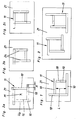
- Fig. 1 illustrated embodiment of a formwork 11 according to the invention three sides of the peripheral edge U a of Abschalprofilen 10 are formed with a standardized length.
- the fourth side of the formwork 11 with the side length L is in contrast to the embodiments according to Fig. 5a to 5c not formed by a projecting Abschalprofil 10 but rather by two set in series Abschalprofilen 10.
- a corresponding grid of different standard lengths for formwork profiles 10 almost all required side lengths L of a precast concrete element to be produced can be switched exclusively with shuttering profiles 10 of standardized length using this method.
- Smaller distances between the series-laid Abschalprofilen 10 do not play a major role, but the distance between the individual Abschalprofilen should not be greater than 1.5 cm in order to avoid spillage of the concrete.
- Fig. 2a to 2c are further embodiments of formwork 11, which are arranged on a pallet 21, shown.
- at least three of the formwork 11 forming Abschalprofile 10 project beyond the outer peripheral edge U a , in each case to the section A.
- the outer peripheral edge U a is defined by the Abschal vom 24 opposite longitudinal sides of the Abschalprofile 10 and is the inner peripheral edge U 1 geometrically similar.
- the peripheral edge of the formwork 11 is formed by the Abschalprofilen 10, the Abschalvid 24 of Abschalprofile 10 forming the inner peripheral edge U I , while the Abschalvid 24 opposite sides of Abschalprofile 10 are part of the outer peripheral edge U A.
- Fig. 2a stand all Abschalprofile 10 over the outer peripheral edge U A , while in the Fig. 2b and 2c only three Abschalprofile 10 protrude beyond the outer peripheral edge U A.
- the laying of Abschalprofile 10 can be done entirely with a formwork robot 8, where it has been found to be particularly advantageous if only one formwork per pallet 21 is arranged, since then the center M of the pallet 21 as a reference point for the shuttering robot. 8 can serve.
- a very short overall time required for the shelling of concrete precast element is achieved, whereby a total of a short cycle time for the synchronous shift and a particularly efficient automation of the pallet circulation system can be achieved.
- Plant 1 shown comprises several stations, which are arranged such that the pallet molds 21, on which the precast concrete elements are produced, these stations in the sense of a production line in particular circulating through.
- This production line comprises a de-scaling station 2, in the region of which a demolition cross-piece 3 is arranged. Subsequent to the de-scaling station 2, a shuttering removal station 4 follows, in which the shuttering profiles 10 are removed from the pallet mold 21. This is followed by the cleaning station 6, which is associated with a cleaning and ⁇ lungsvorraum 5.
- the pallet molds 21 are conveyed to the formwork station 7.
- the shells of concrete precast elements by means of a formwork robot 8, which fetches the Abschalprofile 10 from the formwork bearing 9 and positioned on the pallet mold 21 located in the formwork station 7.
- the Abschalprofile 10 go through after removal of the pallet mold 21 in the formwork removal station 4, a transport and cleaning line 22 before being deposited in the formwork bearing 9.
- the formwork station 7 is followed by a blind station 12, at which no work is carried out.
- the concreting station 14 which is assigned to the concreting device 13, by means of which the concrete is introduced into the formwork 11.
- the concreting station 14 is again followed by a blind station 12 and thereupon the reinforcement station 15, in which by means of a positioning device 16, the reinforcements prepared in the reinforcement preparation station 18 are introduced into the concrete element already concreted but not yet hardened.
- the recovery station 15 is followed by the pick-up station 17 and possibly another blind station 12.
- the pallet molds 21 are picked up by the pick-up station 17 or the subsequent blind station 12 and brought into the curing chamber 20, where the Cement ready element cures under supply of hot air. After setting of the concrete, the pallet mold 21 is transferred from the curing chamber 20 in the de-scaling station 2 and there begins a new round through the production line.
- Fig. 4b the transport routes between the individual stations of the production line are shown in a synchronous shift.
- the pallet molds 21 are moved within a minute from one station to the next, wherein the displacement takes place synchronously.
- Fig. 4c are the individual work processes, which must be performed during a power stroke whose maximum production time is set in the illustrated embodiment with 3.5 minutes.
- the shuttering profiles are removed on the shuttering removal station 4
- the pallet molds 21 are cleaned in the cleaning station 6
- the formwork 11 is produced on the formwork station 7 by the shuttering profiles 10
- concreting the Prefabricated concrete element takes place in the concreting station 14 wherein any reworking can be carried out on the blind station 12, on the rebar station 15, the reinforcements are introduced, while on the pickup 17 any special reinforcements can be introduced.
- the timing of the synchronous shift is composed of the maximum manufacturing time of 3.5 minutes and the transport time of 1 minute, i. the pallet molds 21 are moved every 4.5 minutes between the synchronously connected stations of the production line.
- the pallet molds 21 used in this embodiment are about 8 m long and 3 m wide, with about 88 pallets in a layer through the production line.
- a pallet occupancy of 11.25 m 2 which corresponds to a precast concrete element with 4.5 m Length and 2.5 m width, can be achieved with the inventive system 1, a production of about 1,000 m 2 per shift with a duration of 8 hours.
- the effective production time during one shift is 7 hours, while the cleaning time takes 1 hour.
- the number of personnel required for the monitoring of the plant can be reduced to up to 3 persons, while in plants according to the prior art, in which the feed of the pallet forms was not synchronized, sometimes up to 20 people were necessary ,
- FIG. 5 to 7 shown further embodiments of inventive systems 1 differ from the embodiment according to Fig. 4a to 4c only by the local arrangement of the individual stations of the production line, wherein in the embodiment according to Fig. 5 the stacking device 19 is formed by a stacker crane.
- FIG. 6 illustrated embodiment shows a system 1, with the addition of element ceilings and double walls can be made.
- a dummy station 12 is arranged after the concreting station 14, which is associated with a turning device 23 with a turning frame and suction cups.
- the operation of such Wenderahmen is known per se, which is why a description is omitted here.
- FIG. 7 illustrated embodiment differs from the in Fig. 3 shown example only in that just no such turning device 23 is provided, ie the system according to Fig. 7 serves for the production of flat element ceilings.
Landscapes
- Engineering & Computer Science (AREA)
- Chemical & Material Sciences (AREA)
- Ceramic Engineering (AREA)
- Mechanical Engineering (AREA)
- Manufacturing & Machinery (AREA)
- Automation & Control Theory (AREA)
- Devices For Post-Treatments, Processing, Supply, Discharge, And Other Processes (AREA)
- Moulds, Cores, Or Mandrels (AREA)
Applications Claiming Priority (1)
| Application Number | Priority Date | Filing Date | Title |
|---|---|---|---|
| AT11202007 | 2007-07-17 |
Publications (4)
| Publication Number | Publication Date |
|---|---|
| EP2017047A2 true EP2017047A2 (fr) | 2009-01-21 |
| EP2017047A3 EP2017047A3 (fr) | 2011-02-16 |
| EP2017047B1 EP2017047B1 (fr) | 2013-03-06 |
| EP2017047B2 EP2017047B2 (fr) | 2017-09-27 |
Family
ID=39874142
Family Applications (1)
| Application Number | Title | Priority Date | Filing Date |
|---|---|---|---|
| EP08012905.9A Active EP2017047B2 (fr) | 2007-07-17 | 2008-07-17 | Méhode de sélection d'éléments de coffrage de bordure pour fabriquer un coffrage pour un élément préfabriqué en béton et coffrage correspondant. |
Country Status (3)
| Country | Link |
|---|---|
| EP (1) | EP2017047B2 (fr) |
| DK (1) | DK2017047T4 (fr) |
| ES (1) | ES2411511T5 (fr) |
Cited By (4)
| Publication number | Priority date | Publication date | Assignee | Title |
|---|---|---|---|---|
| EP2942170A1 (fr) * | 2014-05-05 | 2015-11-11 | Elematic Oy Ab | Procédé et appareil pour mouler des produits en béton |
| EP2942171A1 (fr) * | 2014-05-05 | 2015-11-11 | Elematic Oy Ab | Appareil pour mouler des produits de béton |
| CN108145834A (zh) * | 2018-02-26 | 2018-06-12 | 长沙远大住宅工业集团股份有限公司 | 一种用于生产预制构件的可调模具及其安装方法 |
| CN109483715A (zh) * | 2018-11-09 | 2019-03-19 | 江苏汤辰机械装备制造股份有限公司 | 一种预应力电杆生产线 |
Families Citing this family (1)
| Publication number | Priority date | Publication date | Assignee | Title |
|---|---|---|---|---|
| AT516800B1 (de) | 2015-02-13 | 2017-07-15 | Progress Holding Ag | Schalungssystem zur Herstellung einer Schalung für ein Betonfertigteil |
Citations (7)
| Publication number | Priority date | Publication date | Assignee | Title |
|---|---|---|---|---|
| US3730657A (en) * | 1969-11-25 | 1973-05-01 | Nat Res Dev | Mold assembly for pressing concrete |
| DE8814308U1 (fr) * | 1988-11-15 | 1990-03-15 | Kaspar Roeckelein Kg, 8602 Wachenroth, De | |
| EP1273407A1 (fr) * | 2001-07-05 | 2003-01-08 | EBAWE Anlagentechnik GmbH | Robot pour la mise en position des aimants |
| DE10116230C1 (de) * | 2001-04-02 | 2003-06-18 | Weckenmann Anlagentechnik Gmbh | Verfahren und Vorrichtung zur Herstellung von Betonfertigteilen |
| DE10304622B3 (de) * | 2003-02-05 | 2004-12-02 | Beton Kemmler Gmbh & Co. Kg | Verfahren zum Errichten einer Schalung für Betonteile |
| EP1974883A2 (fr) * | 2007-03-24 | 2008-10-01 | Sommer Anlagentechnik GmbH | Procédé et dispositif de positionnement d'éléments de coffrage de bordure sur une table de moulage |
| EP2017049A2 (fr) * | 2007-07-17 | 2009-01-21 | Progress Maschinen & Automation AG | Installation de fabrication d'éléments préfabriqués en béton dotées d'une chaîne de production |
-
2008
- 2008-07-17 ES ES08012905.9T patent/ES2411511T5/es active Active
- 2008-07-17 DK DK08012905.9T patent/DK2017047T4/en active
- 2008-07-17 EP EP08012905.9A patent/EP2017047B2/fr active Active
Patent Citations (7)
| Publication number | Priority date | Publication date | Assignee | Title |
|---|---|---|---|---|
| US3730657A (en) * | 1969-11-25 | 1973-05-01 | Nat Res Dev | Mold assembly for pressing concrete |
| DE8814308U1 (fr) * | 1988-11-15 | 1990-03-15 | Kaspar Roeckelein Kg, 8602 Wachenroth, De | |
| DE10116230C1 (de) * | 2001-04-02 | 2003-06-18 | Weckenmann Anlagentechnik Gmbh | Verfahren und Vorrichtung zur Herstellung von Betonfertigteilen |
| EP1273407A1 (fr) * | 2001-07-05 | 2003-01-08 | EBAWE Anlagentechnik GmbH | Robot pour la mise en position des aimants |
| DE10304622B3 (de) * | 2003-02-05 | 2004-12-02 | Beton Kemmler Gmbh & Co. Kg | Verfahren zum Errichten einer Schalung für Betonteile |
| EP1974883A2 (fr) * | 2007-03-24 | 2008-10-01 | Sommer Anlagentechnik GmbH | Procédé et dispositif de positionnement d'éléments de coffrage de bordure sur une table de moulage |
| EP2017049A2 (fr) * | 2007-07-17 | 2009-01-21 | Progress Maschinen & Automation AG | Installation de fabrication d'éléments préfabriqués en béton dotées d'une chaîne de production |
Cited By (6)
| Publication number | Priority date | Publication date | Assignee | Title |
|---|---|---|---|---|
| EP2942170A1 (fr) * | 2014-05-05 | 2015-11-11 | Elematic Oy Ab | Procédé et appareil pour mouler des produits en béton |
| EP2942171A1 (fr) * | 2014-05-05 | 2015-11-11 | Elematic Oy Ab | Appareil pour mouler des produits de béton |
| RU2687705C2 (ru) * | 2014-05-05 | 2019-05-15 | Элематик Ойй | Способ отливки бетонных изделий |
| RU2687835C2 (ru) * | 2014-05-05 | 2019-05-16 | Элематик Ойй | Способ отливки бетонных изделий |
| CN108145834A (zh) * | 2018-02-26 | 2018-06-12 | 长沙远大住宅工业集团股份有限公司 | 一种用于生产预制构件的可调模具及其安装方法 |
| CN109483715A (zh) * | 2018-11-09 | 2019-03-19 | 江苏汤辰机械装备制造股份有限公司 | 一种预应力电杆生产线 |
Also Published As
| Publication number | Publication date |
|---|---|
| DK2017047T4 (en) | 2018-01-02 |
| EP2017047A3 (fr) | 2011-02-16 |
| ES2411511T3 (es) | 2013-07-05 |
| ES2411511T5 (es) | 2018-01-19 |
| EP2017047B1 (fr) | 2013-03-06 |
| EP2017047B2 (fr) | 2017-09-27 |
| DK2017047T3 (da) | 2013-06-10 |
Similar Documents
| Publication | Publication Date | Title |
|---|---|---|
| EP2119542B1 (fr) | Procédé et machine de fabrication d'éléments préfabriqués en béton, où la fabrication est exécutée sur des moules -palettes | |
| EP2017049A2 (fr) | Installation de fabrication d'éléments préfabriqués en béton dotées d'une chaîne de production | |
| EP2119541A2 (fr) | Procédé de fabrication d'éléments préfabriqués en béton sur des moules de palettes traversent plusieurs stations d'une chaîne de fabrication | |
| EP2017047B1 (fr) | Méhode de sélection d'éléments de coffrage de bordure pour fabriquer un coffrage pour un élément préfabriqué en béton et coffrage correspondant. | |
| EP2667981B1 (fr) | Procédé pour le laminage d'un produit à laminer élaboré par coulée | |
| DE3446092C2 (de) | Verfahren und Einrichtung zum Herstellen von Wandelementen aus Kalksandsteinen | |
| EP1605101A1 (fr) | Procédé et dispositif pour la fabrication d'un panneau multicouche en béton | |
| EP2060374A2 (fr) | Installation de fabrication pour blocs de construction à double paroi | |
| DE2500256A1 (de) | Mauerwerk und verfahren zu seiner herstellung | |
| DE3838711C1 (en) | Process and system for producing double-shelled wall elements | |
| EP2183083A2 (fr) | Procédé et dispositif de fabrication d'un élément de couverture en béton | |
| DE2322139C3 (de) | Batterieform und Verfahren zum Herstellen von Betonplatten | |
| CH630986A5 (de) | Sturz fuer durchgaenge, tuer- und fensteroeffnungen. | |
| EP0139215A1 (fr) | Coffrage à éléments mobiles pour pièces préfabriquées en béton | |
| CH417005A (de) | Bauteilsatz zur Erstellung von Gebäuden aller Art | |
| EP2742798A2 (fr) | Procédé de fabrication de sols pour étables et sol pour étables | |
| DE1509038A1 (de) | Verfahren zum Herstellen von vorgefertigten Wandbauelementen und eine Vorrichtung zu seiner Durchfuehrung | |
| WO2023110000A1 (fr) | Procédé et système de production pour la production automatisée d'un élément en béton à paroi mince au moyen d'un procédé de pulvérisation de béton et d'un moule de coffrage | |
| DE2112977C3 (de) | Verfahren und Vorrichtung zur Herstellung großer paßgerecht aneinander anschließender Fertigbauteile aus Beton | |
| DE3035033C2 (de) | Vorrichtung zur Herstellung von Beton-Schalungssteinen | |
| DE2148145A1 (de) | Verfahren zum Herstellen einer Bau platte, insbesondere Wand oder Decken platte | |
| DE102022110435A1 (de) | Rahmenschalungselement für ein Wandschalungssystem, und Verfahren zur Herstellung eines Rahmenschalungselements | |
| DE194432C (fr) | ||
| DE2635877A1 (de) | Aufzugsschacht fuer wohngebaeude und verfahren zu seiner herstellung | |
| DE826195C (de) | Vorrichtung und Verfahren zur Herstellung von Wandschalungen unter Verwendung von Bauplatten als bleibende Schaltung |
Legal Events
| Date | Code | Title | Description |
|---|---|---|---|
| PUAI | Public reference made under article 153(3) epc to a published international application that has entered the european phase |
Free format text: ORIGINAL CODE: 0009012 |
|
| AK | Designated contracting states |
Kind code of ref document: A2 Designated state(s): AT BE BG CH CY CZ DE DK EE ES FI FR GB GR HR HU IE IS IT LI LT LU LV MC MT NL NO PL PT RO SE SI SK TR |
|
| AX | Request for extension of the european patent |
Extension state: AL BA MK RS |
|
| PUAL | Search report despatched |
Free format text: ORIGINAL CODE: 0009013 |
|
| AK | Designated contracting states |
Kind code of ref document: A3 Designated state(s): AT BE BG CH CY CZ DE DK EE ES FI FR GB GR HR HU IE IS IT LI LT LU LV MC MT NL NO PL PT RO SE SI SK TR |
|
| AX | Request for extension of the european patent |
Extension state: AL BA MK RS |
|
| 17P | Request for examination filed |
Effective date: 20110808 |
|
| AKX | Designation fees paid |
Designated state(s): AT BE BG CH CY CZ DE DK EE ES FI FR GB GR HR HU IE IS IT LI LT LU LV MC MT NL NO PL PT RO SE SI SK TR |
|
| 17Q | First examination report despatched |
Effective date: 20120507 |
|
| GRAP | Despatch of communication of intention to grant a patent |
Free format text: ORIGINAL CODE: EPIDOSNIGR1 |
|
| RIC1 | Information provided on ipc code assigned before grant |
Ipc: B28B 17/00 20060101ALI20120824BHEP Ipc: B28B 7/02 20060101AFI20120824BHEP Ipc: B28B 7/00 20060101ALI20120824BHEP Ipc: B28B 15/00 20060101ALI20120824BHEP |
|
| GRAS | Grant fee paid |
Free format text: ORIGINAL CODE: EPIDOSNIGR3 |
|
| GRAA | (expected) grant |
Free format text: ORIGINAL CODE: 0009210 |
|
| AK | Designated contracting states |
Kind code of ref document: B1 Designated state(s): AT BE BG CH CY CZ DE DK EE ES FI FR GB GR HR HU IE IS IT LI LT LU LV MC MT NL NO PL PT RO SE SI SK TR |
|
| REG | Reference to a national code |
Ref country code: GB Ref legal event code: FG4D Free format text: NOT ENGLISH |
|
| REG | Reference to a national code |
Ref country code: CH Ref legal event code: EP Ref country code: AT Ref legal event code: REF Ref document number: 599341 Country of ref document: AT Kind code of ref document: T Effective date: 20130315 |
|
| REG | Reference to a national code |
Ref country code: IE Ref legal event code: FG4D Free format text: LANGUAGE OF EP DOCUMENT: GERMAN |
|
| REG | Reference to a national code |
Ref country code: DE Ref legal event code: R096 Ref document number: 502008009387 Country of ref document: DE Effective date: 20130502 |
|
| REG | Reference to a national code |
Ref country code: DK Ref legal event code: T3 |
|
| REG | Reference to a national code |
Ref country code: SE Ref legal event code: TRGR |
|
| REG | Reference to a national code |
Ref country code: ES Ref legal event code: FG2A Ref document number: 2411511 Country of ref document: ES Kind code of ref document: T3 Effective date: 20130705 |
|
| PG25 | Lapsed in a contracting state [announced via postgrant information from national office to epo] |
Ref country code: NO Free format text: LAPSE BECAUSE OF FAILURE TO SUBMIT A TRANSLATION OF THE DESCRIPTION OR TO PAY THE FEE WITHIN THE PRESCRIBED TIME-LIMIT Effective date: 20130606 Ref country code: LT Free format text: LAPSE BECAUSE OF FAILURE TO SUBMIT A TRANSLATION OF THE DESCRIPTION OR TO PAY THE FEE WITHIN THE PRESCRIBED TIME-LIMIT Effective date: 20130306 Ref country code: BG Free format text: LAPSE BECAUSE OF FAILURE TO SUBMIT A TRANSLATION OF THE DESCRIPTION OR TO PAY THE FEE WITHIN THE PRESCRIBED TIME-LIMIT Effective date: 20130606 |
|
| REG | Reference to a national code |
Ref country code: NL Ref legal event code: T3 |
|
| REG | Reference to a national code |
Ref country code: LT Ref legal event code: MG4D |
|
| PG25 | Lapsed in a contracting state [announced via postgrant information from national office to epo] |
Ref country code: GR Free format text: LAPSE BECAUSE OF FAILURE TO SUBMIT A TRANSLATION OF THE DESCRIPTION OR TO PAY THE FEE WITHIN THE PRESCRIBED TIME-LIMIT Effective date: 20130607 Ref country code: LV Free format text: LAPSE BECAUSE OF FAILURE TO SUBMIT A TRANSLATION OF THE DESCRIPTION OR TO PAY THE FEE WITHIN THE PRESCRIBED TIME-LIMIT Effective date: 20130306 Ref country code: SI Free format text: LAPSE BECAUSE OF FAILURE TO SUBMIT A TRANSLATION OF THE DESCRIPTION OR TO PAY THE FEE WITHIN THE PRESCRIBED TIME-LIMIT Effective date: 20130306 |
|
| PG25 | Lapsed in a contracting state [announced via postgrant information from national office to epo] |
Ref country code: HR Free format text: LAPSE BECAUSE OF FAILURE TO SUBMIT A TRANSLATION OF THE DESCRIPTION OR TO PAY THE FEE WITHIN THE PRESCRIBED TIME-LIMIT Effective date: 20130306 |
|
| PG25 | Lapsed in a contracting state [announced via postgrant information from national office to epo] |
Ref country code: RO Free format text: LAPSE BECAUSE OF FAILURE TO SUBMIT A TRANSLATION OF THE DESCRIPTION OR TO PAY THE FEE WITHIN THE PRESCRIBED TIME-LIMIT Effective date: 20130306 Ref country code: PT Free format text: LAPSE BECAUSE OF FAILURE TO SUBMIT A TRANSLATION OF THE DESCRIPTION OR TO PAY THE FEE WITHIN THE PRESCRIBED TIME-LIMIT Effective date: 20130708 Ref country code: SK Free format text: LAPSE BECAUSE OF FAILURE TO SUBMIT A TRANSLATION OF THE DESCRIPTION OR TO PAY THE FEE WITHIN THE PRESCRIBED TIME-LIMIT Effective date: 20130306 Ref country code: IS Free format text: LAPSE BECAUSE OF FAILURE TO SUBMIT A TRANSLATION OF THE DESCRIPTION OR TO PAY THE FEE WITHIN THE PRESCRIBED TIME-LIMIT Effective date: 20130706 Ref country code: EE Free format text: LAPSE BECAUSE OF FAILURE TO SUBMIT A TRANSLATION OF THE DESCRIPTION OR TO PAY THE FEE WITHIN THE PRESCRIBED TIME-LIMIT Effective date: 20130306 Ref country code: CZ Free format text: LAPSE BECAUSE OF FAILURE TO SUBMIT A TRANSLATION OF THE DESCRIPTION OR TO PAY THE FEE WITHIN THE PRESCRIBED TIME-LIMIT Effective date: 20130306 |
|
| PG25 | Lapsed in a contracting state [announced via postgrant information from national office to epo] |
Ref country code: CY Free format text: LAPSE BECAUSE OF FAILURE TO SUBMIT A TRANSLATION OF THE DESCRIPTION OR TO PAY THE FEE WITHIN THE PRESCRIBED TIME-LIMIT Effective date: 20130306 Ref country code: PL Free format text: LAPSE BECAUSE OF FAILURE TO SUBMIT A TRANSLATION OF THE DESCRIPTION OR TO PAY THE FEE WITHIN THE PRESCRIBED TIME-LIMIT Effective date: 20130306 |
|
| PLBI | Opposition filed |
Free format text: ORIGINAL CODE: 0009260 |
|
| PLAX | Notice of opposition and request to file observation + time limit sent |
Free format text: ORIGINAL CODE: EPIDOSNOBS2 |
|
| 26 | Opposition filed |
Opponent name: ELEMATIC OY AB Effective date: 20131204 |
|
| REG | Reference to a national code |
Ref country code: DE Ref legal event code: R026 Ref document number: 502008009387 Country of ref document: DE Effective date: 20131204 |
|
| PG25 | Lapsed in a contracting state [announced via postgrant information from national office to epo] |
Ref country code: MC Free format text: LAPSE BECAUSE OF FAILURE TO SUBMIT A TRANSLATION OF THE DESCRIPTION OR TO PAY THE FEE WITHIN THE PRESCRIBED TIME-LIMIT Effective date: 20130306 |
|
| REG | Reference to a national code |
Ref country code: CH Ref legal event code: PL |
|
| GBPC | Gb: european patent ceased through non-payment of renewal fee |
Effective date: 20130717 |
|
| REG | Reference to a national code |
Ref country code: IE Ref legal event code: MM4A |
|
| PG25 | Lapsed in a contracting state [announced via postgrant information from national office to epo] |
Ref country code: GB Free format text: LAPSE BECAUSE OF NON-PAYMENT OF DUE FEES Effective date: 20130717 Ref country code: LI Free format text: LAPSE BECAUSE OF NON-PAYMENT OF DUE FEES Effective date: 20130731 Ref country code: CH Free format text: LAPSE BECAUSE OF NON-PAYMENT OF DUE FEES Effective date: 20130731 |
|
| PLAF | Information modified related to communication of a notice of opposition and request to file observations + time limit |
Free format text: ORIGINAL CODE: EPIDOSCOBS2 |
|
| PLBB | Reply of patent proprietor to notice(s) of opposition received |
Free format text: ORIGINAL CODE: EPIDOSNOBS3 |
|
| PG25 | Lapsed in a contracting state [announced via postgrant information from national office to epo] |
Ref country code: IE Free format text: LAPSE BECAUSE OF NON-PAYMENT OF DUE FEES Effective date: 20130717 |
|
| PLAB | Opposition data, opponent's data or that of the opponent's representative modified |
Free format text: ORIGINAL CODE: 0009299OPPO |
|
| R26 | Opposition filed (corrected) |
Opponent name: ELEMATIC OY AB Effective date: 20131204 |
|
| PG25 | Lapsed in a contracting state [announced via postgrant information from national office to epo] |
Ref country code: MT Free format text: LAPSE BECAUSE OF FAILURE TO SUBMIT A TRANSLATION OF THE DESCRIPTION OR TO PAY THE FEE WITHIN THE PRESCRIBED TIME-LIMIT Effective date: 20130306 |
|
| PG25 | Lapsed in a contracting state [announced via postgrant information from national office to epo] |
Ref country code: HU Free format text: LAPSE BECAUSE OF FAILURE TO SUBMIT A TRANSLATION OF THE DESCRIPTION OR TO PAY THE FEE WITHIN THE PRESCRIBED TIME-LIMIT; INVALID AB INITIO Effective date: 20080717 Ref country code: LU Free format text: LAPSE BECAUSE OF NON-PAYMENT OF DUE FEES Effective date: 20130717 |
|
| REG | Reference to a national code |
Ref country code: FR Ref legal event code: PLFP Year of fee payment: 9 |
|
| PLAB | Opposition data, opponent's data or that of the opponent's representative modified |
Free format text: ORIGINAL CODE: 0009299OPPO |
|
| R26 | Opposition filed (corrected) |
Opponent name: ELEMATIC OYJ Effective date: 20131204 |
|
| RIC2 | Information provided on ipc code assigned after grant |
Ipc: B28B 7/02 20060101ALI20161208BHEP Ipc: B28B 5/04 20060101AFI20161208BHEP Ipc: B28B 15/00 20060101ALI20161208BHEP Ipc: B28B 7/00 20060101ALI20161208BHEP Ipc: B28B 17/00 20060101ALI20161208BHEP |
|
| REG | Reference to a national code |
Ref country code: FR Ref legal event code: PLFP Year of fee payment: 10 |
|
| PUAH | Patent maintained in amended form |
Free format text: ORIGINAL CODE: 0009272 |
|
| STAA | Information on the status of an ep patent application or granted ep patent |
Free format text: STATUS: PATENT MAINTAINED AS AMENDED |
|
| 27A | Patent maintained in amended form |
Effective date: 20170927 |
|
| AK | Designated contracting states |
Kind code of ref document: B2 Designated state(s): AT BE BG CH CY CZ DE DK EE ES FI FR GB GR HR HU IE IS IT LI LT LU LV MC MT NL NO PL PT RO SE SI SK TR |
|
| REG | Reference to a national code |
Ref country code: DE Ref legal event code: R102 Ref document number: 502008009387 Country of ref document: DE |
|
| REG | Reference to a national code |
Ref country code: DK Ref legal event code: T4 Effective date: 20171221 |
|
| REG | Reference to a national code |
Ref country code: SE Ref legal event code: RPEO |
|
| REG | Reference to a national code |
Ref country code: NL Ref legal event code: FP |
|
| REG | Reference to a national code |
Ref country code: ES Ref legal event code: DC2A Ref document number: 2411511 Country of ref document: ES Kind code of ref document: T5 Effective date: 20180119 |
|
| REG | Reference to a national code |
Ref country code: FR Ref legal event code: PLFP Year of fee payment: 11 |
|
| PGFP | Annual fee paid to national office [announced via postgrant information from national office to epo] |
Ref country code: TR Payment date: 20200623 Year of fee payment: 13 |
|
| PG25 | Lapsed in a contracting state [announced via postgrant information from national office to epo] |
Ref country code: TR Free format text: LAPSE BECAUSE OF NON-PAYMENT OF DUE FEES Effective date: 20210717 |
|
| P01 | Opt-out of the competence of the unified patent court (upc) registered |
Effective date: 20230513 |
|
| PGFP | Annual fee paid to national office [announced via postgrant information from national office to epo] |
Ref country code: SE Payment date: 20230630 Year of fee payment: 16 Ref country code: NL Payment date: 20230725 Year of fee payment: 16 |
|
| PGFP | Annual fee paid to national office [announced via postgrant information from national office to epo] |
Ref country code: BE Payment date: 20230628 Year of fee payment: 16 |
|
| PGFP | Annual fee paid to national office [announced via postgrant information from national office to epo] |
Ref country code: IT Payment date: 20230720 Year of fee payment: 16 Ref country code: FI Payment date: 20230713 Year of fee payment: 16 Ref country code: ES Payment date: 20230816 Year of fee payment: 16 Ref country code: AT Payment date: 20230728 Year of fee payment: 16 |
|
| PGFP | Annual fee paid to national office [announced via postgrant information from national office to epo] |
Ref country code: FR Payment date: 20230728 Year of fee payment: 16 Ref country code: DK Payment date: 20230721 Year of fee payment: 16 Ref country code: DE Payment date: 20230731 Year of fee payment: 16 |