EP2016960A2 - Réservoirs de médicaments pour implants médicaux - Google Patents
Réservoirs de médicaments pour implants médicaux Download PDFInfo
- Publication number
- EP2016960A2 EP2016960A2 EP08158973A EP08158973A EP2016960A2 EP 2016960 A2 EP2016960 A2 EP 2016960A2 EP 08158973 A EP08158973 A EP 08158973A EP 08158973 A EP08158973 A EP 08158973A EP 2016960 A2 EP2016960 A2 EP 2016960A2
- Authority
- EP
- European Patent Office
- Prior art keywords
- stent
- drug
- active substance
- depot
- preform
- Prior art date
- Legal status (The legal status is an assumption and is not a legal conclusion. Google has not performed a legal analysis and makes no representation as to the accuracy of the status listed.)
- Granted
Links
Images


Classifications
-
- A—HUMAN NECESSITIES
- A61—MEDICAL OR VETERINARY SCIENCE; HYGIENE
- A61L—METHODS OR APPARATUS FOR STERILISING MATERIALS OR OBJECTS IN GENERAL; DISINFECTION, STERILISATION OR DEODORISATION OF AIR; CHEMICAL ASPECTS OF BANDAGES, DRESSINGS, ABSORBENT PADS OR SURGICAL ARTICLES; MATERIALS FOR BANDAGES, DRESSINGS, ABSORBENT PADS OR SURGICAL ARTICLES
- A61L31/00—Materials for other surgical articles, e.g. stents, stent-grafts, shunts, surgical drapes, guide wires, materials for adhesion prevention, occluding devices, surgical gloves, tissue fixation devices
- A61L31/14—Materials characterised by their function or physical properties, e.g. injectable or lubricating compositions, shape-memory materials, surface modified materials
- A61L31/16—Biologically active materials, e.g. therapeutic substances
-
- A—HUMAN NECESSITIES
- A61—MEDICAL OR VETERINARY SCIENCE; HYGIENE
- A61F—FILTERS IMPLANTABLE INTO BLOOD VESSELS; PROSTHESES; DEVICES PROVIDING PATENCY TO, OR PREVENTING COLLAPSING OF, TUBULAR STRUCTURES OF THE BODY, e.g. STENTS; ORTHOPAEDIC, NURSING OR CONTRACEPTIVE DEVICES; FOMENTATION; TREATMENT OR PROTECTION OF EYES OR EARS; BANDAGES, DRESSINGS OR ABSORBENT PADS; FIRST-AID KITS
- A61F2/00—Filters implantable into blood vessels; Prostheses, i.e. artificial substitutes or replacements for parts of the body; Appliances for connecting them with the body; Devices providing patency to, or preventing collapsing of, tubular structures of the body, e.g. stents
- A61F2/82—Devices providing patency to, or preventing collapsing of, tubular structures of the body, e.g. stents
- A61F2/86—Stents in a form characterised by the wire-like elements; Stents in the form characterised by a net-like or mesh-like structure
- A61F2/90—Stents in a form characterised by the wire-like elements; Stents in the form characterised by a net-like or mesh-like structure characterised by a net-like or mesh-like structure
- A61F2/91—Stents in a form characterised by the wire-like elements; Stents in the form characterised by a net-like or mesh-like structure characterised by a net-like or mesh-like structure made from perforated sheet material or tubes, e.g. perforated by laser cuts or etched holes
- A61F2/915—Stents in a form characterised by the wire-like elements; Stents in the form characterised by a net-like or mesh-like structure characterised by a net-like or mesh-like structure made from perforated sheet material or tubes, e.g. perforated by laser cuts or etched holes with bands having a meander structure, adjacent bands being connected to each other
-
- A—HUMAN NECESSITIES
- A61—MEDICAL OR VETERINARY SCIENCE; HYGIENE
- A61L—METHODS OR APPARATUS FOR STERILISING MATERIALS OR OBJECTS IN GENERAL; DISINFECTION, STERILISATION OR DEODORISATION OF AIR; CHEMICAL ASPECTS OF BANDAGES, DRESSINGS, ABSORBENT PADS OR SURGICAL ARTICLES; MATERIALS FOR BANDAGES, DRESSINGS, ABSORBENT PADS OR SURGICAL ARTICLES
- A61L31/00—Materials for other surgical articles, e.g. stents, stent-grafts, shunts, surgical drapes, guide wires, materials for adhesion prevention, occluding devices, surgical gloves, tissue fixation devices
- A61L31/08—Materials for coatings
- A61L31/10—Macromolecular materials
-
- A—HUMAN NECESSITIES
- A61—MEDICAL OR VETERINARY SCIENCE; HYGIENE
- A61F—FILTERS IMPLANTABLE INTO BLOOD VESSELS; PROSTHESES; DEVICES PROVIDING PATENCY TO, OR PREVENTING COLLAPSING OF, TUBULAR STRUCTURES OF THE BODY, e.g. STENTS; ORTHOPAEDIC, NURSING OR CONTRACEPTIVE DEVICES; FOMENTATION; TREATMENT OR PROTECTION OF EYES OR EARS; BANDAGES, DRESSINGS OR ABSORBENT PADS; FIRST-AID KITS
- A61F2/00—Filters implantable into blood vessels; Prostheses, i.e. artificial substitutes or replacements for parts of the body; Appliances for connecting them with the body; Devices providing patency to, or preventing collapsing of, tubular structures of the body, e.g. stents
- A61F2/82—Devices providing patency to, or preventing collapsing of, tubular structures of the body, e.g. stents
- A61F2/86—Stents in a form characterised by the wire-like elements; Stents in the form characterised by a net-like or mesh-like structure
- A61F2/90—Stents in a form characterised by the wire-like elements; Stents in the form characterised by a net-like or mesh-like structure characterised by a net-like or mesh-like structure
- A61F2/91—Stents in a form characterised by the wire-like elements; Stents in the form characterised by a net-like or mesh-like structure characterised by a net-like or mesh-like structure made from perforated sheet material or tubes, e.g. perforated by laser cuts or etched holes
- A61F2/915—Stents in a form characterised by the wire-like elements; Stents in the form characterised by a net-like or mesh-like structure characterised by a net-like or mesh-like structure made from perforated sheet material or tubes, e.g. perforated by laser cuts or etched holes with bands having a meander structure, adjacent bands being connected to each other
- A61F2002/9155—Adjacent bands being connected to each other
- A61F2002/91558—Adjacent bands being connected to each other connected peak to peak
-
- A—HUMAN NECESSITIES
- A61—MEDICAL OR VETERINARY SCIENCE; HYGIENE
- A61F—FILTERS IMPLANTABLE INTO BLOOD VESSELS; PROSTHESES; DEVICES PROVIDING PATENCY TO, OR PREVENTING COLLAPSING OF, TUBULAR STRUCTURES OF THE BODY, e.g. STENTS; ORTHOPAEDIC, NURSING OR CONTRACEPTIVE DEVICES; FOMENTATION; TREATMENT OR PROTECTION OF EYES OR EARS; BANDAGES, DRESSINGS OR ABSORBENT PADS; FIRST-AID KITS
- A61F2/00—Filters implantable into blood vessels; Prostheses, i.e. artificial substitutes or replacements for parts of the body; Appliances for connecting them with the body; Devices providing patency to, or preventing collapsing of, tubular structures of the body, e.g. stents
- A61F2/82—Devices providing patency to, or preventing collapsing of, tubular structures of the body, e.g. stents
- A61F2/86—Stents in a form characterised by the wire-like elements; Stents in the form characterised by a net-like or mesh-like structure
- A61F2/90—Stents in a form characterised by the wire-like elements; Stents in the form characterised by a net-like or mesh-like structure characterised by a net-like or mesh-like structure
- A61F2/91—Stents in a form characterised by the wire-like elements; Stents in the form characterised by a net-like or mesh-like structure characterised by a net-like or mesh-like structure made from perforated sheet material or tubes, e.g. perforated by laser cuts or etched holes
- A61F2/915—Stents in a form characterised by the wire-like elements; Stents in the form characterised by a net-like or mesh-like structure characterised by a net-like or mesh-like structure made from perforated sheet material or tubes, e.g. perforated by laser cuts or etched holes with bands having a meander structure, adjacent bands being connected to each other
- A61F2002/9155—Adjacent bands being connected to each other
- A61F2002/91591—Locking connectors, e.g. using male-female connections
-
- A—HUMAN NECESSITIES
- A61—MEDICAL OR VETERINARY SCIENCE; HYGIENE
- A61F—FILTERS IMPLANTABLE INTO BLOOD VESSELS; PROSTHESES; DEVICES PROVIDING PATENCY TO, OR PREVENTING COLLAPSING OF, TUBULAR STRUCTURES OF THE BODY, e.g. STENTS; ORTHOPAEDIC, NURSING OR CONTRACEPTIVE DEVICES; FOMENTATION; TREATMENT OR PROTECTION OF EYES OR EARS; BANDAGES, DRESSINGS OR ABSORBENT PADS; FIRST-AID KITS
- A61F2250/00—Special features of prostheses classified in groups A61F2/00 - A61F2/26 or A61F2/82 or A61F9/00 or A61F11/00 or subgroups thereof
- A61F2250/0058—Additional features; Implant or prostheses properties not otherwise provided for
- A61F2250/0096—Markers and sensors for detecting a position or changes of a position of an implant, e.g. RF sensors, ultrasound markers
- A61F2250/0098—Markers and sensors for detecting a position or changes of a position of an implant, e.g. RF sensors, ultrasound markers radio-opaque, e.g. radio-opaque markers
-
- A—HUMAN NECESSITIES
- A61—MEDICAL OR VETERINARY SCIENCE; HYGIENE
- A61L—METHODS OR APPARATUS FOR STERILISING MATERIALS OR OBJECTS IN GENERAL; DISINFECTION, STERILISATION OR DEODORISATION OF AIR; CHEMICAL ASPECTS OF BANDAGES, DRESSINGS, ABSORBENT PADS OR SURGICAL ARTICLES; MATERIALS FOR BANDAGES, DRESSINGS, ABSORBENT PADS OR SURGICAL ARTICLES
- A61L2300/00—Biologically active materials used in bandages, wound dressings, absorbent pads or medical devices
- A61L2300/60—Biologically active materials used in bandages, wound dressings, absorbent pads or medical devices characterised by a special physical form
-
- Y—GENERAL TAGGING OF NEW TECHNOLOGICAL DEVELOPMENTS; GENERAL TAGGING OF CROSS-SECTIONAL TECHNOLOGIES SPANNING OVER SEVERAL SECTIONS OF THE IPC; TECHNICAL SUBJECTS COVERED BY FORMER USPC CROSS-REFERENCE ART COLLECTIONS [XRACs] AND DIGESTS
- Y10—TECHNICAL SUBJECTS COVERED BY FORMER USPC
- Y10T—TECHNICAL SUBJECTS COVERED BY FORMER US CLASSIFICATION
- Y10T156/00—Adhesive bonding and miscellaneous chemical manufacture
- Y10T156/10—Methods of surface bonding and/or assembly therefor
-
- Y—GENERAL TAGGING OF NEW TECHNOLOGICAL DEVELOPMENTS; GENERAL TAGGING OF CROSS-SECTIONAL TECHNOLOGIES SPANNING OVER SEVERAL SECTIONS OF THE IPC; TECHNICAL SUBJECTS COVERED BY FORMER USPC CROSS-REFERENCE ART COLLECTIONS [XRACs] AND DIGESTS
- Y10—TECHNICAL SUBJECTS COVERED BY FORMER USPC
- Y10T—TECHNICAL SUBJECTS COVERED BY FORMER US CLASSIFICATION
- Y10T29/00—Metal working
- Y10T29/49—Method of mechanical manufacture
- Y10T29/49826—Assembling or joining
- Y10T29/49863—Assembling or joining with prestressing of part
- Y10T29/49876—Assembling or joining with prestressing of part by snap fit
Definitions
- the present invention relates to a process for the preparation of an active substance depot, a process for the production of an active substance-coated, endovascular implantable body, an active substance-loaded, endovascular implantable body, which can be produced by a method according to the invention and a kit comprising or consisting of one or more active substance depots, which can be produced according to the invention Method and one or more endovascular implantable body.
- Endovascular implantable bodies are used in medical technology, among other things, to support vascular structures.
- endovascular prostheses or implants in particular endovascular stents.
- Such bodies are also known for the treatment of aneurysms.
- stents have a support structure which is suitable for supporting the wall of a vessel in a suitable manner, thus bridging the vessel or bridging an aneurysm.
- stents are introduced into the vessel in a compressed state and then expanded at the location to be treated and pressed against the vessel wall. This expansion can be done for example by means of a balloon catheter.
- self-expanding stents are also known. These are for example made of a superelastic metal, such as nitinol.
- the dilated blood vessel contracts excessively, so that the vessel cross-section is reduced compared to the unstretched area of the blood vessel (obstruction, so-called negative remodeling).
- an endovascular implant usually a stent.
- the carriers of such drug-containing coating systems are usually made of a biocompatible material, which is either of natural origin or can be obtained by synthetic means. Numerous methods have been developed for applying the coating systems to the stent, such as rotary atomization methods, dipping methods and spraying methods.
- the coating system at least partially covers the surface of the stent, with a release of the pharmacologically active substances in the human or animal body by gradual degradation of the carrier and / or diffusion into the surrounding tissue.
- a drug-containing coating of endovascular stents is usually to be understood as meaning a planar coating.
- the coatings can also consist in that the occurring holes or cavities of the stent geometry are filled or one-sided or punctiform coatings on the support structure of the stents exist.
- such coatings are technologically very demanding as well as time-consuming and cost-intensive.
- the desired surface properties of the implant to be produced may possibly not be achieved. In order to achieve these properties, however, sometimes complex process steps for the pretreatment of the respective surface are necessary, which could possibly have consequences for the biocompatibility to an additional manufacturing step.
- active ingredient-loaded polymer layers can lead to mechanical problems of the layer during dilatation of the stent with high drug loading.
- a further object of the present invention is to provide an endovascular implantable body comprising one or more drug depots with one or more active agents, wherein the or the active ingredients can be adjusted specifically with respect to the elution time and concentration. Another object is to reduce unwanted implant side effects, eg, increase the risk of restenosis and / or thrombosis.
- Another object of the present invention relates to a drug-loaded, endovascular implantable body, produced by a method according to the invention.
- Another object of the present invention relates to a use of one or more inventively prepared drug depots for producing a drug-loaded, endovascular implantable body, preferably stents, for the prophylaxis or treatment of a stenosis, aneurism or tumor tissue in a human or animal body.
- the present invention is based on the finding that an active substance depot according to the invention, which is manufactured separately from the actual endovascular implantable body, can be technologically more easily optimized with respect to the elution characteristic of the incorporated active substance and, secondly, independently of the material used implantable body, preferably stents, can be mechanically connected directly to this.
- the active substance depots produced according to the invention which are mechanically connected to the endovascular implantable bodies, preferably in a form-fitting manner, can solve the stated tasks in an improved manner compared with the prior art.
- an implantable body according to the invention with drug depots according to the invention therefore consist in particular in the fact that, as a result of the technological separation of the production of the implantable body and the drug depot, a direct drug loading of the implantable body is made possible independently of the material of the implantable body.
- a further advantage is that a loading of an implantable body produced according to the invention with one or more drug depots according to the invention makes possible a flexible drug therapy of the implantable body which is tailor-made for the respective disease.
- a loading of an implant with one or more drug depots according to the invention is technologically simple and, accordingly, already existing endovascular implantable bodies, be they drug-coated or not, can be loaded by means of the drug depots according to the invention (after). It is also possible, in particular in different spatial regions of the endovascular implantable body, preferably stents, to load different numbers of drug depots. Inventive examples of this are disclosed in FIGS. 2a and 2 B shown. Such embodiments according to the invention may be of particular advantage when an individually tailored to a patient drug therapy is required. In this case, even the attending physician himself can tailor the loading of an endovascular implantable body, preferably stents.
- a further advantage of the objects according to the invention is that not only one but also several active substances can be present in the active substance depot, in particular in (different) dosages which - due to the limitation by, for example, the layer thickness - can not be achieved with conventional coatings of implantable bodies.
- time-graded elution curves of one or more active substances in the active substance depot can be realized here, for example a continuous increase of one or more active substances, in order gradually to accustom the body into which the implant with active substance depot is implanted to the active substance (s).
- stent geometries can arise which take up a measure of the volume of the vessel lumen that during implantation Stent (Deliverability) problems may arise when passing through stenoses or other bottlenecks (large "Crossing Profile").
- active substance depots according to the invention which are clipped to a body to be implanted, preferably a stent, allows firstly the utilization of the space between the struts or bars of the stents to be implanted or the clinging of the active substance depots according to the invention to be implanted body, in particular stents.
- drug depots can be used, which may include a high concentration of one or more drugs.
- High active ingredient concentrations are particularly advantageous for active ingredients from the group of limus drugs for the treatment of restenosis, in particular comprising sirolimus (rapamycin), zotarolimus (Abt-578), tacrolimus (Fk506), everolimus, Biolimus, especially Biolimus A9, paclitaxel (Taxol ), Pimecrolimus, lipid regulators, preferably fibrates, immunosuppressants, vasodilators, preferably sartans, calcium channel blockers, calcineurin inhibitors, preferably tacrolimus, antiphlogistics, preferably cortisone and diclofenac, anti-inflammatory agents, preferably imidazoles, antiallergics, oligonucleotides, preferably decoy oligodeoxynucleotide (dODN), estrogens, preferably Genistein, endothelium formers, preferably fibrin, steroids, proteins / peptides, proliferation inhibitors, analgesics
- cytostatic agent if the implant is placed in a tumor tissue delivery vessel, preferably near the tumor tissue, are released there directly into the blood vessel and into high blood levels Concentration can be supplied directly to the bloodstream to the tumor tissue. There is the possibility that side effects associated with the cytotoxic agents used may be reduced.
- FIGS. 3a and 5a Inventive embodiments of the preferred objects presented above are exemplified in FIGS. 3a and 5a shown.
- Another advantage of the subject invention is that several drug depots, each comprising different drugs, with an endovascular implantable body can be connected, and thus a multiple-drug-release (release of multiple drugs), especially dual-drug-release (release of two drugs) or a triple-drug-realease (release of three drugs) is achieved by what a conventional coating process technologically hardly or only with increased cost and / or time can be achieved.
- An example of such an inventive embodiment is in FIG. 2a described.
- Another advantage is that interactions between the active ingredients used and the material used for the implantable body, preferably stent, can be reduced. This is achieved in particular by producing the endovascular implantable body, preferably a stent, separately from the active substance depot according to the invention.
- This is particularly useful when using degradable (basic) bodies, such as e.g. degradable stents, especially degradable metal stents, since here a direct drug coating with the (basic) body, due to the interaction with the material of the body, by means of conventional methods only difficult or sometimes not at all possible.
- the terminal connection of one or more drug depots to degradable body since the distance between the mutually influencing materials is increased and thus the mutual influence can be reduced.
- an implantable body usually represents a degradable or non-degradable cardiovascular or peripheral stent and a stent for other cavities, such as the esophagus, the bile duct, the urethra, the prostate or the trachea.
- implantable body according to the present invention is local drug delivery implants that are implanted endovascularly in the blood or other cavities.
- implantable bodies can represent neuroapplications, as well as subcutaneous applications for continuous drug release (for example hormone preparations), but also stimulation electrons or regional drug delivery applications.
- degradable bodies preferably stents, comprise materials degradable as materials or degradable polymer.
- the alloy in particular comprising magnesium, iron, zinc and tungsten, is to be selected in its composition so that it is biocorrodible.
- biocorrodible materials are alloys in which degradation occurs in a physiological environment, which ultimately leads to the entire stent or the part of the stent formed from the material losing its mechanical integrity. Alloy is understood to mean predominantly a mechanical structure whose main component is magnesium, iron, zinc or tungsten.
- the main component is the alloy component whose weight fraction of the alloy is highest. A proportion of the main component is preferably more than 50% by weight, more preferably more than 70% by weight.
- the material is a magnesium alloy, it preferably contains yttrium and other rare earth metals, since such an alloy is distinguished by its physicochemical properties and high biocompatibilities, in particular its degradation products.
- alloys of the WE series WE 43 etc.
- magnesium alloys of the composition rare earth metals 5.5 to 9.9% by weight of which yttrium contains from 0.0 to 5.5% by weight and the rest comprising zirconium ⁇ 1% by weight.
- These magnesium alloys have already confirmed their particular suitability experimentally and in initial clinical trials, ie they show a high biocompatibility, favorable processing properties, good mechanical properties and an adequate corrosion behavior for the purposes.
- Scandium (21), yttrium (37), lanthanum (57) and the 14 elements following lanthanum (57) are predominantly used under the collective name "rare earth metals”.
- connection of drug depots according to the invention with magnesium stents can be reduced due to the spatial distance undesirable interactions of the acidic degradable polymeric drug depot and the basic degrading magnesium stent, especially the resulting acceleration of magnesium corrosion and thus a faster loss of stent collapse pressure.
- the increased spatial separation can also slow the degradation of the polymer in the drug depot, resulting in less tissue irritation and no peeling of the polymer layer from the implanted stent.
- endovascularly implantable stents are used as the implantable body, then all the usual stent geometries can be used. Particular preference is given to stent geometries which are known in US 6,896,695 . US 2006/241742 . US 5,968,083 (Tenax) EP 1 430 854 (Helix design) US 6,197,047 and EP 0 884 985 to be discribed.
- the drug depot (s) are mechanically connected to the catheter to be used after crimping the stent onto a catheter to be used.
- An advantage of this sequence is that the drug depots or the drug depots are not affected by the process of crimping in their matrix.
- the mechanical connection of the active substance depot produced according to the invention with the endovascularly implantable body, preferably an endovascular stent can preferably be configured in a form-fitting manner with a web or strut of a stent.
- a C-shaped gripper which preferably clasps the active substance depot with the implantable body, preferably a stent, in a form-fitting manner.
- Such an inventive embodiment is, for example, in FIG. 1b . 2c . 3b . 4c . 4e . 5b and 5c shown.
- all other attachment measures of the stents according to the invention which are considered by those skilled in the art due to its expertise, are hereby also claimed.
- FIG. 4b This includes in particular embodiments in a hook shape, which exemplifies in FIG. 4b being represented.
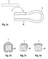
- drug depots according to the invention can be adhered to an implantable body, preferably stents, which can be used, for example, in US Pat FIGS. 7a to 7d is pictured.
- suitable active substance depots preferably have concave locations which conform to the struts of the struts of an implantable stent.
- Suitable adhesives are preferably superglue from the class of acrylates, fibrin glue, fats and polysaccharides.
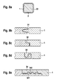
- drug depots which completely enclose a strut or a strut of a stent and are connected to one another in a suitable manner such that the depot of active substance can not roll off the strut or the strut (see FIGS. 8a to 8e ).
- Per implantable body preferably stent, one or more drug depots, which may differ in the drug concentration and / or in the drug type, can be clipped.
- the drug depots are usually designed so that they interfere with implantation of the body in a vascular system as little as possible and are therefore preferably in existing interstices of the implantable body, preferably the stent, housed or they cover the body, preferably the stent, as a thin, low hoses.
- an active substance depot produced according to the invention is characterized in that it is in the form of a tube (see, by way of example Figures 2c and 4c ), Film form (see, by way of example FIG. 5b ), Preform (see example Figures 1b . 3b . 4b . 4e and 5c ) or as (relatively) stiff nets.
- hose designates a round body which is round or oval in cross-section and optionally open on two sides.
- preform describes a negative form of a position of the implant, to which it is attached later.
- This "preform” may optionally be flexible or stiff.
- an active substance depot produced in accordance with the invention is used in the form of a tube, it is preferably produced by means of a pure extrusion method, tubular blowing method or deep-drawing process. In rare cases, but also via joining or adhesive technology. Under joining technique, in the case of the tube, shrinkage or "fitted" assembly by e.g. Plugging in to understand.
- the hose represents only an intermediate step in the production of the medicament carrier, it can also be slit, lined on the inside with a bonding agent and finally with the stent, by e.g. Unroll, be connected. Alternatively, the stent itself may be provided with the primer and then replaced by e.g. Unrolling be connected to the slotted tube.
- method step c) of the method according to the invention additionally comprises bringing the depot of active substance in tube form to the length of a stent and / or strut of the stent and the tube shape along the axis is slit and the thus processed hose is formed so that it represents a clip which is mechanically connected to the webs and / or struts of the stent by means of force and / or adhesive insert, preferably form-fitting.
- an active substance depot produced according to the invention in film form is used, it is preferably produced by means of an extrusion process, casting process or rolling process. Sometimes films can also be drawn from a melt or solution.
- the process according to the invention for preparing the active substance depot in process step c) additionally comprises processing the drug depot in film form in such a way that the film form i) is joined to the surface of the abluminal surface of the body, preferably of the stent or ii) to a part thereof ,
- a film can therefore be applied around the entire stent or around a strut or strut of a stent and especially as in FIG. 5a attached to the struts at the ends of an implantable stent. If a film is applied to the ends of an implant, preferably a stent, the film should be such that it does not enter the lumen and thus impair the unobstructed blood flow.
- the film form i) or ii) of the active substance depot used according to the invention is preferably characterized in that the film shape can be perforated according to the geometry of the abluminal surface of the stent Foil material corresponds to the areas of the material of the stent.
- the films described could also be perforated, for example, to allow the blood flow in the side branches of blood vessels.
- Inventive drug depots in film form can also by means of suitable means, preferably C-shaped gripper hooks, etc., with the endovascular implantable body, preferably positively connected.
- suitable means preferably C-shaped gripper hooks, etc.
- Such a preferred embodiment of the invention is particularly in FIGS. 5a and 5b shown.
- the active substance depot according to the invention is produced as a preform, it is preferably characterized in that it is a hollow body which is produced, for example, by means of a hollow-body blowing method or injection molding method, wherein the preform is the negative of a position of the implant, preferably a stent, on which it is to be applied , represents.
- a preform is produced according to a method according to the invention for producing the active substance depot, it is preferably designed such that it adheres to the body, preferably a stent (US Pat. Fig. 7a to 7d ), clicked together ( Fig. 8a to 8e ) or by welding together the upper and lower sides can be applied and thus with the body, preferably stent, preferably mechanically positively connectable.
- a stent US Pat. Fig. 7a to 7d
- clicked together Fig. 8a to 8e
- an active ingredient depot is used as a preform for the connection with an endovascular implantable stent, it is preferably processed in accordance with the invention such that the preform is slit along the axis or is already cast with a slot and this preform is designed such that it represents a clip which can be mechanically connected to the stent by means of a force and / or adhesive insert, preferably with a positive fit ( Fig. 4e ).
- an active substance depot is used as a preform for connection to struts or struts of an endovascular implantable stent
- the preform is processed according to the method according to the invention so that it is brought to the length of the webs or struts of the stent, slotted along the axis or already cast with slot present and this preform is designed so that it represents a clip which is mechanically connected to the webs or struts of the stent by means of force and / or adhesive insert, preferably form-fitting.
- FIGS. 1a, 1b, 3b, 4c, 4e and 5c Such an inventive embodiment is exemplified in FIGS. 1a, 1b, 3b, 4c, 4e and 5c ,
- the preform may consist of two parts, which are then welded around the strut or strut.
- Cytostatics include, in particular, DNA-alkylating substances, in particular nitrogen-nitrogen compounds and nitrosourea compounds; Platinum compounds; hydroxyurea compounds; Antimetabolites, preferably folic acid antagonists, purine analogs and pyrimidine analogs; Microtubule inhibitors, preferably winker alkaloids, taxanes, preferably paclitaxel and dozetaxel; Topoisomerase inhibitors; Antibiotics, preferably anthracyclines, more preferably danorobizine, doxorubicin, epirubicin and idarubicin, anactinomycins, especially dactinomycin, methoxanthrone, asarcine and ansarkrin, mitomycin C and bleomycin; as well as various cytostatics from the group asparaginase, metefusin and imatinib; Hormones, preferably glucocorticoids, in particular prednisone, sex hormones, particularly preferably
- an endovascularly implantable body preferably a stent, more preferably a degradable stent
- the method preferably additionally comprises that the or one of the bodies from step a) of the invention Process before connection to the drug depot in step c) is coated wholly or partially with one or more adjuvants, wherein the aid or the auxiliaries are designed so that they enhance the mechanical connection of the drug depot or with the body or bodies.
- adhesives are preferably used as an aid, preferably pure plastic solvents, superglue from the class of acrylates, fibrin glue, fats and polysaccharides.
- the manufacturing method according to the invention for the production of the drug-loaded endovascular implantable body preferably a (degradable) stent, a tubular form used as a drug depot, it is preferably designed so that it corresponds to the length of a web or strut of the stent corresponds, is slotted along the axis and thus represents a clip which is mechanically connected in method step c) by means of force and / or adhesive insert with the web or strut of the stent, preferably form-fitting.
- an active substance depot produced according to the invention in film form is used, preferably film i) or ii) is used, then the endovascular implantable body, preferably a (degradable) stent, in step c) with the abluminal surface on the film i) or ii) unrolled and thus by means of force and / or adhesive, preferably form-fitting, mechanically connected.
- the manufacturing method according to the invention is characterized in that the preform is designed in such a way that it is glued, clipped or welded together in step c) onto the implantable body, preferably stent, and thus mechanically, preferably with a positive fit is connected.
- the preform can also be attached to the implantable body by shrinking with gentle heat supply, so that the active ingredient (s) are not damaged.
- a method according to the invention for producing the drug-loaded endovascular implantable body is characterized in that in a further step, the preform is machined so that it is slit along the axis or already cast slot and this preform represents a clip in step c ) is mechanically connected to the body, preferably stent, by means of force and / or adhesive, preferably positive.
- the preform is brought to the length of a web or a strut of the stent, slit along the axis or already cast with slot, so that this preform is a clip in step c) with the web or strut of the stent by means of force and / or adhesive insert, preferably positively, mechanically connected.
- the drug-loaded, endovascular implantable body represents a stent which can be produced by a method according to the invention, it is preferably a degradable endovascular implantable stent, more preferably a degradable metal stent.
- the preferred embodiments described herein for the inventive manufacturing method are also applicable to the present inventive implantable body, preferably (degradable) stent.
- the preferred embodiments thereof are those which are implantable on the drug depot or the endovascular Obtain body, further explained by the preferred embodiments described in relation to the manufacturing method according to the invention.
- Preferred embodiments for the inventive use of one or more drug depots for producing an active ingredient-loaded implantable body or for the method according to the invention for the prophylaxis or treatment of a stenosis, aneurism or tumor tissue can be achieved by incorporating one or more of the aforementioned preferred embodiments into the body become.
- the active substance (s) are specially applied for the particular therapy.
- a high concentration of active ingredient (s) is preferably used for the prophylaxis or therapy of a tumor tissue.
- drug depot forms are preferred for an embodiment of the invention in this regard, which may contain a high concentration of active ingredient. Examples of suitable drug depots in FIGS. 3a . 3b . 5a . 5b and 5c shown.
- a drug-loaded stent preparable according to the invention is implanted in a blood vessel which carries blood to the tumor, preferably near the tumor tissue.
- the figures show, by way of example, sections of the abluminal surface of stent geometries of a stent basic body or the active substance depots according to the invention in a perspective view or in cross section.
- the present invention is not limited to the stent geometries shown here or to the arrangement of the drug depots shown.
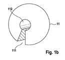
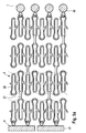
- FIG. 1a shows an abluminal section of a stent geometry 2, which in US 6,896,695 is described, together with a plurality of, preferably form-fitting, angeklippten drug depots 1 in the form of slotted beads 11, wherein the drug depot beads 11 according to the invention have a cavity and slotted 111 are that the beads in particular to the longitudinal connectors (struts) 21 or alternatively to the straight Regions of the stent struts 22 (the latter embodiment not shown), preferably form-fitting, can be clipped (see also FIG. 1b ).
- Such an embodiment according to the invention is preferred for one or more active substances which have a good distribution in the vascular tissue after release of the active substance (s).
- a further advantage is that, due to the high proportion of stent body 2 that is not loaded with active substance, improved growth with endothelial cells (EC; endothelialization) compared to conventionally completely coated stents of the prior art can be made possible. This improved endothelialization of the stent 2 can also reduce the risk of thrombosis associated with the implantation of an endovascular implantable body.
- EC endothelialization
- FIG. 1b shows a view of drug depot beads 11 according to the invention with a slot 111 and a cavity 112 which is designed so that it can be clipped to a Strut 21 or web 22 of a stent 2, preferably a form-fitting.
- active substance depot beads 11 may comprise one or more active substances according to the invention.
- the drug depot beads 11 used may each comprise different concentrations of one or more drugs.
- Inventive drug depots in the form of beads 11 are preferably prepared by casting, film and joining methods.
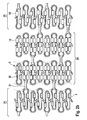
- FIG. 2a shows an abluminal section of a stent geometry 2, which in US 6,896,695 with a plurality of clipped drug depots 1 in tube form 12, wherein the tubes 12 are configured to be slotted along the longitudinal side 126 and have a cavity 127, in particular to the struts 21 or alternatively to the straight regions the stent struts 22 of a stent 2, preferably form-fitting, to be clipped (see also Figure 2c ).
- Such an active ingredient loading according to the invention is preferably of interest for a nationwide loading with two, three or more drug depots (121, 122 and 123). In this way, a multiple-drug release, in particular a dual-drug release (release of 2 drugs) or a triple drug release (release of 3 drugs) are made possible.
- Such a configuration is furthermore particularly preferred for those drug depots whose polymer can not be connected to the basic body of the stent or the implantable body in the absence of suitable solvent or polymer adhesion to the stent material used in accordance with conventional coating methods.
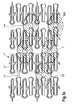
- FIG. 2b shows a modification FIG. 2a
- the regions 23 of the stent have a lower loading with the drug depots 12, ie, fewer drug depots 12 per surface of the stent 2, compared to the regions 24 of the stent.
- the agent depots 12 are preferably clipped onto the web 22 or strut 21 of a stent 2 in a form-fitting manner.
- Figure 2c shows a view of the slotted drug depots according to the invention in tube form 12, a slot 124 and a cavity 125 which is designed so that it can be clipped to a Strut 21 or web 22 of a stent 2, preferably a form-fitting.
- An agent depot 12 may typically contain one or more agents. Agent depots 121, 122 and 123 differ in that they each comprise different active ingredients.
- Inventive drug depots in tube form 12, 121, 122 and 123 are preferably prepared by means of extrusion process, tube blowing and deep drawing process. In rare cases, joining or gluing techniques are used.
- FIG. 3a shows a plan view of a abluminal section of a stent geometry 2 with a plurality of slotted substance depots 13 in preform, which are on Struts 21 or webs 22 of a stent 2, preferably clipped form-fitting.
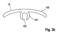
- the agent depot 13 according to the invention is designed such that it comprises a C-shaped gripper 131 with slot 133, which can be clipped onto a strut 21 or web 22 of a stent 2, preferably with a positive fit, and a matrix 132.
- Active substance depots 13 according to the invention comprise one or more active substances and are preferably produced by means of casting methods, if appropriate combined with milling or plugging together or by means of a suitable joining method (heat bonding, gluing) or injection molding.
- agent depot 13 By means of agent depot 13 according to FIG. 3a or 3b a high concentration of active ingredient in the drug depot 13 is made possible.
- the active ingredient concentration is preferably localized in the matrix material 132 of the drug depot 13, which is arranged on the abluminal surface of the implantable body, preferably stents. This makes it possible that little to no drug is released from the drug depot 13 into the vessel lumen of an implanted stent 2 and thus an endothelialization of the stent 2 is not delayed or prevented. Accordingly, the risk of restenosis or thrombosis formation is reduced according to the invention.
- FIG. 4a shows a plan view of a abluminal section of a stent geometry 2 with multiple drug depots 14 and 15, which are clipped on the abluminal surface of Struts.
- This embodiment according to the invention is comparable to the embodiment according to the invention in FIG. 3a , with the difference that the drug depots 14 and 15, in contrast to the drug depot 13 are not freely rotatably angeklippt around the struts 21 and webs 22 of the stent 2.
- FIG. 4a shows a plan view of a abluminal section of a stent geometry 2 with multiple drug depots 14 and 15, which are clipped on the abluminal surface of Struts.
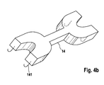
- FIG. 4b shows a perspective view of an inventive drug depot 14.
- This comprises means 141 which are formed so that they are with a Strut 21 or a web 22 of a stent 2, preferably form-fitting, mechanically connectable.
- the means 141 represents a hook shape.
- agents according to the invention can be produced from the same material as the active agent depot.
- An active substance depot 14 according to the invention is furthermore preferably designed such that it at least partially covers the abluminal surface of a strut 21 and / or web 22 of the stent 2 in the clip-on state.
- little to no polymer, preferably no active ingredient-containing polymer of the drug depot 14 or 15, is present on the luminal surface of the stent 2.
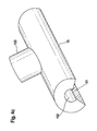
- Figure 4c shows a perspective view of an inventive drug depot 15.
- Agent depot 15 is configured in tube or preform, wherein it has a slot 151 and a cavity 152 which is configured so that it to a Strut 21 or web 22, preferably form-fitting clipped can be.
- the agent depot 15 comprises material that is designed such that, when clipped on, it covers the abluminal surface of a strut 21 or web 22.
- the slit 151 is so broad that the active substance depot 15 has little or no matrix material of the active agent depot 15 in the state clipped onto the strut 21 or web 22 of the stent 2 on the luminal side.
- FIG. 4d shows a plan view of a abluminal section of a stent geometry 2 with multiple drug depots 16.
- the drug depots are designed so that they clipped both luminal and the corresponding abluminal regions of one or more webs 22 and / or struts 21 of a stent 2, preferably positive fit , cover.
- Figure 4e shows a perspective view of an agent depot 16 that is designed so that it covers both lumbar as well as the corresponding abluminal areas of one or more webs 22 and / or struts 21 of a stent 2, preferably positive fit, when clipped.
- the active substance depot 16 has an upper region 161, which preferably covers the abluminal surface of a stent 2, and a lower region 162, which preferably covers the luminal surface of a stent 2.
- an agent depot 16 according to the invention has a slot 163, which allows the depot 16 to be attached to one or more webs 22 and Struts 21 can be clipped.
- an active substance depot according to the invention comprises cavities 164 which are formed such that in the clipped state, preferably in a form-fitting manner, the webs 22 and struts 21 of a stent 2 comprise.
- cavities 164 which are formed such that in the clipped state, preferably in a form-fitting manner, the webs 22 and struts 21 of a stent 2 comprise.
- only one or more active substances are incorporated in the area 161 of the active substance depot. This has the advantage that the diminished delivery of the agent (s) to the vessel lumen does not reduce or prevent the endothelialization of the stent 2.
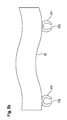
- FIG. 5a 2 shows a plan view of an abluminal section of a stent geometry 2 with terminal, preferably form-fitting, clipped-on active substance depots in the form of a band 17 or of a body 18.
- DES drug-eluting stent
- the stent is not used for its support structure, but serves as an anchorage for the drug depots 17 and 18 according to the invention.
- a stent loaded in this manner according to the invention is preferably implanted in a blood vessel which carries blood to the tumor tissue, preferably close to the stent tumor tissue. This makes it possible that the highest possible concentration of active ingredient used reaches the tumor tissue.
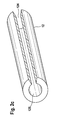
- FIG. 5b shows a perspective view of an inventive drug depot in band form 17.
- the band 17 also has means 171, which allow the band 17 to a endovascular implantable body, preferably stent, can be mechanically connected.
- a means 171 in the form of a C-shaped gripper is used which has a slot 171.
- the C-shaped gripper 171 comprises, preferably in a form-fitting manner, a web 22 or a strut 21 of a stent 2.
- This active substance depot 17 can comprise one or more active substances.
- FIG. 5c shows a cross-section of an active substance depot in the form of a body 18.
- the body 18 also has means 181, which enable the body 18 to be mechanically connected to an endovascular implantable body, preferably a stent.
- a means 181 in the form of a C-shaped gripper is used which has a slot 181.
- the C-shaped gripper 181, preferably in a form-fitting manner comprises a web 22 or a strut 21 of a stent 2
- Agent depot 18 may include one or more agents.
- the C-shaped grippers can be made, for example, by injection molding, reservoir, by joining (gluing, melting) or by any other suitable method described above.
- FIG. 6a shows a plan view of a abluminal section of a stent geometry 2 with terminally attached drug depots 19 in cap form, which are shrunk onto the webs 22 of a stent 2, preferably a positive fit.
- the active substance depots 19 are shrunk onto the round end regions of the stent 2 so as not to damage the active substance or substances.
- FIG. 6b For example, a perspective view of an agent depot 19 with the surface 191 toward the vessel lumen or vascular tissue and the inner surface 192 toward the ridges 22 is shown.
- Figure 7a shows a schematic abluminal plan view of a section of a stent geometry 2 with stent struts 22 and a drug depot 1 in film form, which is preferably adhered to the stent strut 22 by means of superglue from the class acrylates, fibrin glue, fats or polysaccharides.
- the active substance depot 1 can have concave locations, and thus be glued to the stent struts 22 in a form-fitting manner.
- FIG. 7b shows a cross section of a stent strut 22 with a drug depot 1 in foil form.
- FIG. 7c shows a cross-section of a stent strut 22 with drug depot 1, wherein the drug depot is disposed on the abluminal surface of the stent strut 22 and accordingly only a small proportion of the active substance (s) contained in the drug depot 1 is delivered to the vessel lumen.
- This is advantageous because it promotes endothelialization of the stent and reduces the side effects of the stent as a foreign body.
- FIG. 7d also shows a cross-section of a stent strut 22 with drug depot 1, which is also arranged abluminally on the stent strut. Again, only small amounts of active ingredient are released from the drug depot 1 to the vessel lumen.
- drug depot 1 also arranged abluminally on the stent strut.
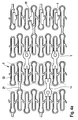
- FIG. 8a shows a cross section of a stent strut 22 with a stent strut surrounded agent depot 1 and connection mechanism 30th
- connection mechanism 31 of the drug depot 1 is shown enlarged.
- connection mechanism 31 is at the one end of the drug depot to a notch, which may optionally be introduced by milling in the drug depot and at the opposite second end of the drug depot to a protuberance, which is suitable to be inserted into the notch suitable , And so to effect a firm connection of the two ends of the drug depot.
- connection mechanism 32 of the drug depot 1 is shown enlarged.
- the connection mechanism 32 is an L-shaped connection mechanism, with the opposite ends of the drug depots each having mirror-inverted L-shaped ends which can be mated with one another to effect a firm connection of the ends of the drug reservoir 1.
- connection mechanism 33 of the drug depot 1 is shown enlarged.
- the connecting mechanism 33 is characterized in that the two opposite ends of the active substance depot 1 are each in the form of a hook and are hooked into one another, thus effecting a firm connection of the ends of the active substance depot 1.
- connection mechanism 34 of the drug depot 1 is shown enlarged.
- the connection mechanism 34 corresponds in principle to the connection mechanism in L-shape, as already in FIG. 8c
- the connecting mechanism 34 differs in that the superimposed surface 341 has protuberances and the surface 342 corresponding notches and thus cause a firm connection of the ends of the drug depot 1.
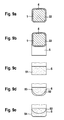
- FIG. 9a shows a cross-section of a stent strut 22 with agent depot 1, which is arranged overlapping in the area 4.
- This type of compound can either via the residual stress of the drug depot 1 or via a suitable adhesive in position 4 are attached.
- Preferred adhesives include superglue from the class of acrylates, fibrin glue, fats and polysaccharides.
- FIG. 9b shows a cross section of a stent strut 22 with agent depot 1, which overlaps in the region 4 and another drug reservoir 5, which is preferably arranged abluminally.
- the active substance depot 1 preferably has no active ingredient.
- the drug depot is brought into shape either by internal stress or by additional bonding in the area 4.
- the reservoir 5 of the drug depot 1 one or more active ingredients, preferably antiproliferative agents.
- FIG. 9c schematically is a cross section of the drug reservoir 5 of the drug depot 1, as in FIG. 9b , now shown as drug reservoir 51 with a homogeneous drug distribution of one or more drugs.
- FIG. 9d is the drug reservoir 5 of the drug depot 1 according to FIG. 9b shown as a reservoir 52, wherein the active ingredient is homogeneously distributed and over this layer, a top coat 53 is coated, which influences the release of the active substance or in the reservoir 52.
- FIG. 9e becomes a drug reservoir 5 of an agent depot 1 according to FIG. 9b shown in a preferred embodiment.
- the reservoir 52 contains a homogeneous distribution of an active substance and the reservoir 54 a homogeneous distribution of another active substance. This enables a dual-drug application.
Landscapes
- Health & Medical Sciences (AREA)
- Life Sciences & Earth Sciences (AREA)
- Engineering & Computer Science (AREA)
- Biomedical Technology (AREA)
- Veterinary Medicine (AREA)
- Public Health (AREA)
- General Health & Medical Sciences (AREA)
- Animal Behavior & Ethology (AREA)
- Heart & Thoracic Surgery (AREA)
- Vascular Medicine (AREA)
- Cardiology (AREA)
- Transplantation (AREA)
- Oral & Maxillofacial Surgery (AREA)
- Physics & Mathematics (AREA)
- Optics & Photonics (AREA)
- Surgery (AREA)
- Epidemiology (AREA)
- Chemical & Material Sciences (AREA)
- Medicinal Chemistry (AREA)
- Molecular Biology (AREA)
- Materials For Medical Uses (AREA)
- Media Introduction/Drainage Providing Device (AREA)
- Medicines That Contain Protein Lipid Enzymes And Other Medicines (AREA)
Applications Claiming Priority (1)
| Application Number | Priority Date | Filing Date | Title |
|---|---|---|---|
| DE102007034041A DE102007034041A1 (de) | 2007-07-20 | 2007-07-20 | Medikamentendepots für medizinische Implantate |
Publications (3)
| Publication Number | Publication Date |
|---|---|
| EP2016960A2 true EP2016960A2 (fr) | 2009-01-21 |
| EP2016960A3 EP2016960A3 (fr) | 2013-04-03 |
| EP2016960B1 EP2016960B1 (fr) | 2016-03-23 |
Family
ID=39967992
Family Applications (1)
| Application Number | Title | Priority Date | Filing Date |
|---|---|---|---|
| EP08158973.1A Not-in-force EP2016960B1 (fr) | 2007-07-20 | 2008-06-25 | Réservoirs de médicaments pour implants médicaux |
Country Status (3)
| Country | Link |
|---|---|
| US (2) | US7913371B2 (fr) |
| EP (1) | EP2016960B1 (fr) |
| DE (1) | DE102007034041A1 (fr) |
Cited By (4)
| Publication number | Priority date | Publication date | Assignee | Title |
|---|---|---|---|---|
| EP2491965A3 (fr) * | 2011-02-24 | 2014-04-23 | Biotronik AG | Implant et son procédé de fabrication |
| WO2014065885A1 (fr) * | 2012-10-23 | 2014-05-01 | Abbott Cardiovascular Systems Inc. | Endoprothèse vasculaire dilatable à ballon fabriquée à base de plla |
| EP2462961A3 (fr) * | 2010-12-08 | 2014-08-27 | Biotronik AG | Implant constitué d'une matière première biocorrodable et doté d'un revêtement comprenant un adhésif tissulaire |
| WO2015039880A1 (fr) * | 2013-09-17 | 2015-03-26 | Cortronik GmbH | Endoprothèse intra-luminale ayant une distribution de principe actif optimisée |
Families Citing this family (59)
| Publication number | Priority date | Publication date | Assignee | Title |
|---|---|---|---|---|
| US7727221B2 (en) | 2001-06-27 | 2010-06-01 | Cardiac Pacemakers Inc. | Method and device for electrochemical formation of therapeutic species in vivo |
| US7758892B1 (en) * | 2004-05-20 | 2010-07-20 | Boston Scientific Scimed, Inc. | Medical devices having multiple layers |
| US8840660B2 (en) * | 2006-01-05 | 2014-09-23 | Boston Scientific Scimed, Inc. | Bioerodible endoprostheses and methods of making the same |
| US8089029B2 (en) | 2006-02-01 | 2012-01-03 | Boston Scientific Scimed, Inc. | Bioabsorbable metal medical device and method of manufacture |
| US20070224244A1 (en) * | 2006-03-22 | 2007-09-27 | Jan Weber | Corrosion resistant coatings for biodegradable metallic implants |
| US8048150B2 (en) * | 2006-04-12 | 2011-11-01 | Boston Scientific Scimed, Inc. | Endoprosthesis having a fiber meshwork disposed thereon |
| US8052743B2 (en) | 2006-08-02 | 2011-11-08 | Boston Scientific Scimed, Inc. | Endoprosthesis with three-dimensional disintegration control |
| ES2357661T3 (es) | 2006-09-15 | 2011-04-28 | Boston Scientific Scimed, Inc. | Endoprótesis bioerosionables con capas inorgánicas bioestables. |
| US8057534B2 (en) | 2006-09-15 | 2011-11-15 | Boston Scientific Scimed, Inc. | Bioerodible endoprostheses and methods of making the same |
| CA2663250A1 (fr) * | 2006-09-15 | 2008-03-20 | Boston Scientific Limited | Endoprotheses biodegradables et procedes de fabrication |
| WO2008034013A2 (fr) * | 2006-09-15 | 2008-03-20 | Boston Scientific Limited | Dispositifs médicaux et procédés de réalisation desdits dispositifs |
| CA2663762A1 (fr) * | 2006-09-18 | 2008-03-27 | Boston Scientific Limited | Endoprothese |
| JP2010503463A (ja) * | 2006-09-18 | 2010-02-04 | ボストン サイエンティフィック リミテッド | 医療機器の生分解の制御 |
| US20080069858A1 (en) * | 2006-09-20 | 2008-03-20 | Boston Scientific Scimed, Inc. | Medical devices having biodegradable polymeric regions with overlying hard, thin layers |
| ES2506144T3 (es) * | 2006-12-28 | 2014-10-13 | Boston Scientific Limited | Endoprótesis bioerosionables y procedimiento de fabricación de las mismas |
| US20140094901A1 (en) * | 2007-03-30 | 2014-04-03 | DePuy Synthes Products, LLC | Radiopaque marker for vascular devices |
| US8545548B2 (en) | 2007-03-30 | 2013-10-01 | DePuy Synthes Products, LLC | Radiopaque markers for implantable stents and methods for manufacturing the same |
| US8052745B2 (en) * | 2007-09-13 | 2011-11-08 | Boston Scientific Scimed, Inc. | Endoprosthesis |
| US20090143855A1 (en) * | 2007-11-29 | 2009-06-04 | Boston Scientific Scimed, Inc. | Medical Device Including Drug-Loaded Fibers |
| US20100008970A1 (en) * | 2007-12-14 | 2010-01-14 | Boston Scientific Scimed, Inc. | Drug-Eluting Endoprosthesis |
| WO2009094501A1 (fr) * | 2008-01-24 | 2009-07-30 | Medtronic, Inc. | Marqueurs pour valvules cardiaques prothétiques |
| US7998192B2 (en) * | 2008-05-09 | 2011-08-16 | Boston Scientific Scimed, Inc. | Endoprostheses |
| US8236046B2 (en) | 2008-06-10 | 2012-08-07 | Boston Scientific Scimed, Inc. | Bioerodible endoprosthesis |
| US20100004733A1 (en) * | 2008-07-02 | 2010-01-07 | Boston Scientific Scimed, Inc. | Implants Including Fractal Structures |
| DE102008040786A1 (de) * | 2008-07-28 | 2010-02-04 | Biotronik Vi Patent Ag | Biokorrodierbares Implantat mit einer Beschichtung enthaltend eine wirkstofftragende Polymermatrix |
| US7985252B2 (en) * | 2008-07-30 | 2011-07-26 | Boston Scientific Scimed, Inc. | Bioerodible endoprosthesis |
| US8382824B2 (en) * | 2008-10-03 | 2013-02-26 | Boston Scientific Scimed, Inc. | Medical implant having NANO-crystal grains with barrier layers of metal nitrides or fluorides |
| DE102008044316A1 (de) * | 2008-12-03 | 2010-06-10 | Biotronik Vi Patent Ag | Wirkstoffbeschichtetes Medizinprodukt, Verfahren zu dessen Herstellung und dessen Verwendungen |
| DE102009005792B4 (de) * | 2009-01-22 | 2019-06-19 | Feg Textiltechnik Forschungs- Und Entwicklungsgesellschaft Mbh | Medizinisches Implantat mit Oberflächenbeschichtung |
| EP2403546A2 (fr) | 2009-03-02 | 2012-01-11 | Boston Scientific Scimed, Inc. | Implants médicaux à tamponnage spontané |
| US8435281B2 (en) | 2009-04-10 | 2013-05-07 | Boston Scientific Scimed, Inc. | Bioerodible, implantable medical devices incorporating supersaturated magnesium alloys |
| EP2266638A3 (fr) * | 2009-06-25 | 2014-08-13 | Biotronik VI Patent AG | Solution d'accélérateur et procédé pour le durcissement de résines durcissables |
| US9283305B2 (en) | 2009-07-09 | 2016-03-15 | Medtronic Vascular, Inc. | Hollow tubular drug eluting medical devices |
| US20110022158A1 (en) * | 2009-07-22 | 2011-01-27 | Boston Scientific Scimed, Inc. | Bioerodible Medical Implants |
| US8828474B2 (en) | 2009-09-20 | 2014-09-09 | Medtronic Vascular, Inc. | Apparatus and methods for loading a drug eluting medical device |
| US20110070358A1 (en) | 2009-09-20 | 2011-03-24 | Medtronic Vascular, Inc. | Method of forming hollow tubular drug eluting medical devices |
| US8678046B2 (en) | 2009-09-20 | 2014-03-25 | Medtronic Vascular, Inc. | Apparatus and methods for loading a drug eluting medical device |
| US8381774B2 (en) * | 2009-09-20 | 2013-02-26 | Medtronic Vascular, Inc. | Methods for loading a drug eluting medical device |
| DE102010006965A1 (de) | 2010-02-05 | 2011-08-11 | Continental Automotive GmbH, 30165 | Vorrichtung und Verfahren zur Bestimmung eines Bereichs einer Batteriekennlinie |
| US8668732B2 (en) * | 2010-03-23 | 2014-03-11 | Boston Scientific Scimed, Inc. | Surface treated bioerodible metal endoprostheses |
| US8562670B2 (en) * | 2010-04-01 | 2013-10-22 | Abbott Cardiovascular Systems Inc. | Implantable prosthesis with depot retention feature |
| WO2011126708A1 (fr) * | 2010-04-06 | 2011-10-13 | Boston Scientific Scimed, Inc. | Endoprothèse |
| WO2011163236A2 (fr) | 2010-06-21 | 2011-12-29 | Zorion Medical, Inc. | Implants bioabsorbables |
| JP5902165B2 (ja) * | 2010-08-02 | 2016-04-13 | コーディス・コーポレイションCordis Corporation | 異なる螺旋状領域を有する可撓性螺旋状ステント |
| US8632846B2 (en) | 2010-09-17 | 2014-01-21 | Medtronic Vascular, Inc. | Apparatus and methods for loading a drug eluting medical device |
| US8616040B2 (en) | 2010-09-17 | 2013-12-31 | Medtronic Vascular, Inc. | Method of forming a drug-eluting medical device |
| US8333801B2 (en) * | 2010-09-17 | 2012-12-18 | Medtronic Vascular, Inc. | Method of Forming a Drug-Eluting Medical Device |
| US8920867B2 (en) * | 2010-10-19 | 2014-12-30 | Covidien Lp | Methods of forming self-supporting films for delivery of therapeutic agents |
| US8986369B2 (en) | 2010-12-01 | 2015-03-24 | Zorion Medical, Inc. | Magnesium-based absorbable implants |
| US10561509B2 (en) | 2013-03-13 | 2020-02-18 | DePuy Synthes Products, Inc. | Braided stent with expansion ring and method of delivery |
| EP2967938B1 (fr) | 2013-03-14 | 2017-03-01 | Medtronic Vascular Inc. | Procédé pour fabriquer une endoprothèse, et endoprothèse fabriquée par ce procédé |
| EP2799036A1 (fr) * | 2013-04-02 | 2014-11-05 | Biotronik AG | Endoprthèse intraluminale et son procédé de fabrication |
| US10206796B2 (en) | 2014-08-27 | 2019-02-19 | DePuy Synthes Products, Inc. | Multi-strand implant with enhanced radiopacity |
| US10076428B2 (en) | 2016-08-25 | 2018-09-18 | DePuy Synthes Products, Inc. | Expansion ring for a braided stent |
| US10292851B2 (en) | 2016-09-30 | 2019-05-21 | DePuy Synthes Products, Inc. | Self-expanding device delivery apparatus with dual function bump |
| AU2019204522A1 (en) | 2018-07-30 | 2020-02-13 | DePuy Synthes Products, Inc. | Systems and methods of manufacturing and using an expansion ring |
| US10278848B1 (en) | 2018-08-06 | 2019-05-07 | DePuy Synthes Products, Inc. | Stent delivery with expansion assisting delivery wire |
| US10456280B1 (en) | 2018-08-06 | 2019-10-29 | DePuy Synthes Products, Inc. | Systems and methods of using a braided implant |
| US11039944B2 (en) | 2018-12-27 | 2021-06-22 | DePuy Synthes Products, Inc. | Braided stent system with one or more expansion rings |
Citations (9)
| Publication number | Priority date | Publication date | Assignee | Title |
|---|---|---|---|---|
| EP0884985A1 (fr) | 1996-10-28 | 1998-12-23 | BIOTRONIK Mess- und Therapiegeräte GmbH & Co Ingenieurbüro Berlin | Extenseur |
| US5968083A (en) | 1997-11-12 | 1999-10-19 | Pacesetter, Inc. | Active overload detection and protection circuit for implantable cardiac therapy devices |
| US6197047B1 (en) | 1997-05-23 | 2001-03-06 | BIOTRONIK MESS- UND THERAPIEGERäTE GMBH & CO. INGENIEURBURO BERLIN | Stent |
| EP1389471A1 (fr) | 2002-08-13 | 2004-02-18 | BIOTRONIK Mess- und Therapiegeräte GmbH & Co Ingenieurbüro Berlin | Stent ayant un revêtement de poly-L-lactide de poids moléculaire élevé |
| EP1430854A1 (fr) | 2002-12-20 | 2004-06-23 | Biotronik GmbH & Co. KG | Stent |
| US6896695B2 (en) | 2000-03-15 | 2005-05-24 | Biotronik Mess-Und Therapiegeraete Gmbh & Co. | Stent |
| WO2005079335A2 (fr) | 2004-02-12 | 2005-09-01 | The University Of Akron | Revetements de dispositifs medicaux fixes mecaniquement |
| US20050220843A1 (en) | 2004-04-06 | 2005-10-06 | Dewitt David M | Coating compositions for bioactive agents |
| US20060241742A1 (en) | 2003-06-23 | 2006-10-26 | Biotronik Gmbh & Co. Kg | Stent comprising a coating system |
Family Cites Families (6)
| Publication number | Priority date | Publication date | Assignee | Title |
|---|---|---|---|---|
| US5741327A (en) * | 1997-05-06 | 1998-04-21 | Global Therapeutics, Inc. | Surgical stent featuring radiopaque markers |
| US5935162A (en) * | 1998-03-16 | 1999-08-10 | Medtronic, Inc. | Wire-tubular hybrid stent |
| DE60232710D1 (de) * | 2001-02-16 | 2009-08-06 | Cordis Corp | Verfahren zur herstellung eines ballonkatheter- stentapplikationssystems mit furchen |
| US7223282B1 (en) * | 2001-09-27 | 2007-05-29 | Advanced Cardiovascular Systems, Inc. | Remote activation of an implantable device |
| DE102005039126A1 (de) * | 2005-08-18 | 2007-02-22 | Lothar Sellin | Parylene-beschichtete expandierbare Vorrichtung |
| DE102006038232A1 (de) * | 2006-08-07 | 2008-02-14 | Biotronik Vi Patent Ag | Endoprothese und Verfahren zur Herstellung einer solchen |
-
2007
- 2007-07-20 DE DE102007034041A patent/DE102007034041A1/de not_active Withdrawn
-
2008
- 2008-06-25 EP EP08158973.1A patent/EP2016960B1/fr not_active Not-in-force
- 2008-07-21 US US12/177,041 patent/US7913371B2/en not_active Expired - Fee Related
-
2011
- 2011-03-28 US US13/073,174 patent/US8721712B2/en active Active
Patent Citations (9)
| Publication number | Priority date | Publication date | Assignee | Title |
|---|---|---|---|---|
| EP0884985A1 (fr) | 1996-10-28 | 1998-12-23 | BIOTRONIK Mess- und Therapiegeräte GmbH & Co Ingenieurbüro Berlin | Extenseur |
| US6197047B1 (en) | 1997-05-23 | 2001-03-06 | BIOTRONIK MESS- UND THERAPIEGERäTE GMBH & CO. INGENIEURBURO BERLIN | Stent |
| US5968083A (en) | 1997-11-12 | 1999-10-19 | Pacesetter, Inc. | Active overload detection and protection circuit for implantable cardiac therapy devices |
| US6896695B2 (en) | 2000-03-15 | 2005-05-24 | Biotronik Mess-Und Therapiegeraete Gmbh & Co. | Stent |
| EP1389471A1 (fr) | 2002-08-13 | 2004-02-18 | BIOTRONIK Mess- und Therapiegeräte GmbH & Co Ingenieurbüro Berlin | Stent ayant un revêtement de poly-L-lactide de poids moléculaire élevé |
| EP1430854A1 (fr) | 2002-12-20 | 2004-06-23 | Biotronik GmbH & Co. KG | Stent |
| US20060241742A1 (en) | 2003-06-23 | 2006-10-26 | Biotronik Gmbh & Co. Kg | Stent comprising a coating system |
| WO2005079335A2 (fr) | 2004-02-12 | 2005-09-01 | The University Of Akron | Revetements de dispositifs medicaux fixes mecaniquement |
| US20050220843A1 (en) | 2004-04-06 | 2005-10-06 | Dewitt David M | Coating compositions for bioactive agents |
Cited By (9)
| Publication number | Priority date | Publication date | Assignee | Title |
|---|---|---|---|---|
| EP2462961A3 (fr) * | 2010-12-08 | 2014-08-27 | Biotronik AG | Implant constitué d'une matière première biocorrodable et doté d'un revêtement comprenant un adhésif tissulaire |
| EP2491965A3 (fr) * | 2011-02-24 | 2014-04-23 | Biotronik AG | Implant et son procédé de fabrication |
| WO2014065885A1 (fr) * | 2012-10-23 | 2014-05-01 | Abbott Cardiovascular Systems Inc. | Endoprothèse vasculaire dilatable à ballon fabriquée à base de plla |
| CN104736108A (zh) * | 2012-10-23 | 2015-06-24 | 艾博特心血管系统公司 | 由plla制成的球囊可扩展支架 |
| JP2015533578A (ja) * | 2012-10-23 | 2015-11-26 | アボット カルディオバスキュラー システムズ インコーポレーテッドAbbott Cardiovascular Systems Inc. | Pllaで作られたバルーン膨張ステント |
| US9517150B2 (en) | 2012-10-23 | 2016-12-13 | Abbott Cardiovascular Systems Inc. | Time-dependent polymer scaffolds |
| US9956097B2 (en) | 2012-10-23 | 2018-05-01 | Abbott Cardiovascular Systems Inc. | Methods for vascular restoration therapy |
| US11135074B2 (en) | 2012-10-23 | 2021-10-05 | Abbott Cardiovascular Systems Inc. | Methods for vascular restoration therapy |
| WO2015039880A1 (fr) * | 2013-09-17 | 2015-03-26 | Cortronik GmbH | Endoprothèse intra-luminale ayant une distribution de principe actif optimisée |
Also Published As
| Publication number | Publication date |
|---|---|
| EP2016960A3 (fr) | 2013-04-03 |
| US20090024210A1 (en) | 2009-01-22 |
| EP2016960B1 (fr) | 2016-03-23 |
| US8721712B2 (en) | 2014-05-13 |
| US7913371B2 (en) | 2011-03-29 |
| DE102007034041A1 (de) | 2009-01-22 |
| US20110178593A1 (en) | 2011-07-21 |
Similar Documents
| Publication | Publication Date | Title |
|---|---|---|
| EP2016960B1 (fr) | Réservoirs de médicaments pour implants médicaux | |
| EP2018834B1 (fr) | Stent en métal dégradable doté d'un revêtement contenant des additifs | |
| DE60114576T2 (de) | Intraluminare, durchlöcherte, radial ausweitbare prothese zur zufuhr von medikamenten | |
| DE602004010895T2 (de) | Abnehmbare und rückholbare stentanordnung | |
| DE602004011847T2 (de) | Stent mit Phenoxyharz als Grundierung | |
| US20050149163A1 (en) | Reduced restenosis drug containing stents | |
| DE602004010344T2 (de) | Katheter ohne Ballon zum Einsetzen eines Stents | |
| US9358096B2 (en) | Methods of treatment with drug eluting stents with prolonged local elution profiles with high local concentrations and low systemic concentrations | |
| EP2133044A2 (fr) | Implant chargé de matière active | |
| EP2070558A2 (fr) | Implants dotés d'une membrane permettant la diffusion contrôlée d'agent actif | |
| WO2004105646A2 (fr) | Dispositifs et procedes pour le traitement des regions stenosees | |
| EP2186531A2 (fr) | Augmentation de l'efficacité de produits médicaux libérant des agents actifs pharmaceutiques par association avec un inhibiteur de la protéine de transport glycoprotéine P | |
| EP2090269A1 (fr) | Système d'introduction d'une endoprothèse intraluminale et procédé de fabrication d'un tel système | |
| EP2329799A1 (fr) | Système de cathéter avec dispositif de coupage pour la gaine du cathéter | |
| EP2563287B1 (fr) | Endoprothèse à élution médicamenteuse repliée et système de pose d'endoprothèse | |
| US7377937B2 (en) | Stent-graft assembly with elution openings | |
| DE102007034991A1 (de) | Verfahren zur Herstellung eines gecrimpten Stents, Verwendung einer Polymerbeschichtung und Medizinprodukte | |
| DE102006038239A1 (de) | Wirkstoffbeschichtete medizinische Implantate | |
| EP2289575B1 (fr) | Implant médical contenant une substance anti-oxydante | |
| EP2327380B1 (fr) | Stent doté d'éléments de fonction | |
| EP2446917A1 (fr) | Cathéter, système d'introduction d'une endoprothèse intraluminale et son procédé de fabrication | |
| US20060129229A1 (en) | Stent | |
| DE102008040143A1 (de) | Degradierbarer Magnesium-Stent oder Medizinprodukt mit Beschichtung umfassend Dipyridamol | |
| US20100106234A1 (en) | Medical Devices With Extended Drug Diffusion Pathway | |
| DE60114770T2 (de) | Immunotoleranter Stent mit Oberflächen-Mikrostruktur |
Legal Events
| Date | Code | Title | Description |
|---|---|---|---|
| PUAI | Public reference made under article 153(3) epc to a published international application that has entered the european phase |
Free format text: ORIGINAL CODE: 0009012 |
|
| AK | Designated contracting states |
Kind code of ref document: A2 Designated state(s): AT BE BG CH CY CZ DE DK EE ES FI FR GB GR HR HU IE IS IT LI LT LU LV MC MT NL NO PL PT RO SE SI SK TR |
|
| AX | Request for extension of the european patent |
Extension state: AL BA MK RS |
|
| PUAL | Search report despatched |
Free format text: ORIGINAL CODE: 0009013 |
|
| AK | Designated contracting states |
Kind code of ref document: A3 Designated state(s): AT BE BG CH CY CZ DE DK EE ES FI FR GB GR HR HU IE IS IT LI LT LU LV MC MT NL NO PL PT RO SE SI SK TR |
|
| AX | Request for extension of the european patent |
Extension state: AL BA MK RS |
|
| RIC1 | Information provided on ipc code assigned before grant |
Ipc: A61L 31/16 20060101AFI20130228BHEP Ipc: A61L 31/10 20060101ALI20130228BHEP |
|
| 17P | Request for examination filed |
Effective date: 20130926 |
|
| RBV | Designated contracting states (corrected) |
Designated state(s): AT BE BG CH CY CZ DE DK EE ES FI FR GB GR HR HU IE IS IT LI LT LU LV MC MT NL NO PL PT RO SE SI SK TR |
|
| AKX | Designation fees paid |
Designated state(s): CH DE GB IE LI NL |
|
| GRAP | Despatch of communication of intention to grant a patent |
Free format text: ORIGINAL CODE: EPIDOSNIGR1 |
|
| RIC1 | Information provided on ipc code assigned before grant |
Ipc: A61L 31/16 20060101AFI20150615BHEP Ipc: A61F 2/915 20130101ALI20150615BHEP Ipc: A61F 2/91 20130101ALI20150615BHEP Ipc: A61L 31/10 20060101ALI20150615BHEP |
|
| INTG | Intention to grant announced |
Effective date: 20150703 |
|
| GRAS | Grant fee paid |
Free format text: ORIGINAL CODE: EPIDOSNIGR3 |
|
| GRAA | (expected) grant |
Free format text: ORIGINAL CODE: 0009210 |
|
| AK | Designated contracting states |
Kind code of ref document: B1 Designated state(s): CH DE GB IE LI NL |
|
| REG | Reference to a national code |
Ref country code: GB Ref legal event code: FG4D Free format text: NOT ENGLISH |
|
| REG | Reference to a national code |
Ref country code: CH Ref legal event code: EP |
|
| REG | Reference to a national code |
Ref country code: IE Ref legal event code: FG4D Free format text: LANGUAGE OF EP DOCUMENT: GERMAN |
|
| REG | Reference to a national code |
Ref country code: DE Ref legal event code: R096 Ref document number: 502008013964 Country of ref document: DE |
|
| REG | Reference to a national code |
Ref country code: NL Ref legal event code: FP |
|
| REG | Reference to a national code |
Ref country code: DE Ref legal event code: R097 Ref document number: 502008013964 Country of ref document: DE |
|
| PLBE | No opposition filed within time limit |
Free format text: ORIGINAL CODE: 0009261 |
|
| STAA | Information on the status of an ep patent application or granted ep patent |
Free format text: STATUS: NO OPPOSITION FILED WITHIN TIME LIMIT |
|
| 26N | No opposition filed |
Effective date: 20170102 |
|
| REG | Reference to a national code |
Ref country code: DE Ref legal event code: R081 Ref document number: 502008013964 Country of ref document: DE Owner name: BIOTRONIK AG, CH Free format text: FORMER OWNER: BIOTRONIK VI PATENT AG, BAAR, CH |
|
| REG | Reference to a national code |
Ref country code: GB Ref legal event code: 732E Free format text: REGISTERED BETWEEN 20180719 AND 20180725 Ref country code: NL Ref legal event code: PD Owner name: BIOTRONIK AG; CH Free format text: DETAILS ASSIGNMENT: CHANGE OF OWNER(S), ASSIGNMENT; FORMER OWNER NAME: BIOTRONIK VI PATENT AG Effective date: 20180608 |
|
| PGFP | Annual fee paid to national office [announced via postgrant information from national office to epo] |
Ref country code: DE Payment date: 20210625 Year of fee payment: 14 Ref country code: NL Payment date: 20210621 Year of fee payment: 14 |
|
| PGFP | Annual fee paid to national office [announced via postgrant information from national office to epo] |
Ref country code: CH Payment date: 20210623 Year of fee payment: 14 Ref country code: GB Payment date: 20210623 Year of fee payment: 14 Ref country code: IE Payment date: 20210622 Year of fee payment: 14 |
|
| REG | Reference to a national code |
Ref country code: DE Ref legal event code: R119 Ref document number: 502008013964 Country of ref document: DE |
|
| REG | Reference to a national code |
Ref country code: CH Ref legal event code: PL |
|
| REG | Reference to a national code |
Ref country code: NL Ref legal event code: MM Effective date: 20220701 |
|
| GBPC | Gb: european patent ceased through non-payment of renewal fee |
Effective date: 20220625 |
|
| PG25 | Lapsed in a contracting state [announced via postgrant information from national office to epo] |
Ref country code: NL Free format text: LAPSE BECAUSE OF NON-PAYMENT OF DUE FEES Effective date: 20220701 |
|
| PG25 | Lapsed in a contracting state [announced via postgrant information from national office to epo] |
Ref country code: LI Free format text: LAPSE BECAUSE OF NON-PAYMENT OF DUE FEES Effective date: 20220630 Ref country code: IE Free format text: LAPSE BECAUSE OF NON-PAYMENT OF DUE FEES Effective date: 20220625 Ref country code: CH Free format text: LAPSE BECAUSE OF NON-PAYMENT OF DUE FEES Effective date: 20220630 |
|
| PG25 | Lapsed in a contracting state [announced via postgrant information from national office to epo] |
Ref country code: GB Free format text: LAPSE BECAUSE OF NON-PAYMENT OF DUE FEES Effective date: 20220625 Ref country code: DE Free format text: LAPSE BECAUSE OF NON-PAYMENT OF DUE FEES Effective date: 20230103 |