EP2016601B1 - Leistungsschalter, insbesondere hochstromschalter - Google Patents
Leistungsschalter, insbesondere hochstromschalter Download PDFInfo
- Publication number
- EP2016601B1 EP2016601B1 EP07728946A EP07728946A EP2016601B1 EP 2016601 B1 EP2016601 B1 EP 2016601B1 EP 07728946 A EP07728946 A EP 07728946A EP 07728946 A EP07728946 A EP 07728946A EP 2016601 B1 EP2016601 B1 EP 2016601B1
- Authority
- EP
- European Patent Office
- Prior art keywords
- pole
- moving contact
- welded
- fixed contact
- conductor rail
- Prior art date
- Legal status (The legal status is an assumption and is not a legal conclusion. Google has not performed a legal analysis and makes no representation as to the accuracy of the status listed.)
- Active
Links
Images


Classifications
-
- H—ELECTRICITY
- H01—ELECTRIC ELEMENTS
- H01H—ELECTRIC SWITCHES; RELAYS; SELECTORS; EMERGENCY PROTECTIVE DEVICES
- H01H33/00—High-tension or heavy-current switches with arc-extinguishing or arc-preventing means
- H01H33/60—Switches wherein the means for extinguishing or preventing the arc do not include separate means for obtaining or increasing flow of arc-extinguishing fluid
- H01H33/66—Vacuum switches
- H01H33/6606—Terminal arrangements
-
- H—ELECTRICITY
- H01—ELECTRIC ELEMENTS
- H01H—ELECTRIC SWITCHES; RELAYS; SELECTORS; EMERGENCY PROTECTIVE DEVICES
- H01H1/00—Contacts
- H01H1/58—Electric connections to or between contacts; Terminals
-
- H—ELECTRICITY
- H01—ELECTRIC ELEMENTS
- H01H—ELECTRIC SWITCHES; RELAYS; SELECTORS; EMERGENCY PROTECTIVE DEVICES
- H01H1/00—Contacts
- H01H1/58—Electric connections to or between contacts; Terminals
- H01H1/5822—Flexible connections between movable contact and terminal
-
- H—ELECTRICITY
- H01—ELECTRIC ELEMENTS
- H01H—ELECTRIC SWITCHES; RELAYS; SELECTORS; EMERGENCY PROTECTIVE DEVICES
- H01H1/00—Contacts
- H01H1/58—Electric connections to or between contacts; Terminals
- H01H2001/5894—Electric connections to or between contacts; Terminals the extension of the contact being welded to a wire or a bus
Definitions
- Object of the present invention is to develop a circuit breaker of the type mentioned, which has a higher current carrying capacity.
- connection means are electron beam welded. Electron beam welding is particularly advantageous because the welds are executable in high precision.
- FIG. 2 shows the solid contact 12 of the vacuum interrupter 5 in the form of a cylindrical bolt is connected to the first connection means 13 in the form of a copper-shaped plate having a bolt of the fixed contact 12 corresponding recess in the area 17 encircling electron beam welded, creating a non-positive and cohesive connection between the fixed contact 12 and the second connection means 13 is formed.
- the second connection means 13 is also further electron beam welded to the first busbars 6 in the region 18.
- To stabilize an aluminum spacer 19 is disposed between the busbars.
- FIG. 3 shows a detailed view in the region of the moving contact of the vacuum interrupter 5 from the FIG. 1 ,
- the moving contact 8 is electron beam welded at its tapered end 20 in the area 21 circumferentially with the second connection means 11 in the form of a copper-shaped plate with a corresponding recess of the bolt 20 of the moving contact 8 recess.
- Flexible conductors 22 and 23 are also electron beam welded in the regions 24 to the second connection means 11 and electron beam welded at 26 and 27 to the second bus bar 7. Due to the non-positive and cohesive connection in the regions 21, 24, 25, 26 and 27, no further screw connections are required as fastening means in the region of the flexible current conductors 22 and 23 and the moving contact 8.
Landscapes
- Physics & Mathematics (AREA)
- Electromagnetism (AREA)
- High-Tension Arc-Extinguishing Switches Without Spraying Means (AREA)
- Gas-Insulated Switchgears (AREA)
- Linear Motors (AREA)
- Electric Propulsion And Braking For Vehicles (AREA)
Description
- Die Erfindung betrifft einen Leistungsschalter, insbesondere einen Hochstromschalter, mit mindestens einer Poleinheit mit einem Polkopf und einem Polträger und einer dazwischen angeordneten Vakuumschaltröhre mit einem Festkontakt und einem Bewegkontakt, wobei der Festkontakt über ein erstes Anschlussmittel mit einer ersten Stromschiene der Poleinheit und der Bewegkontakt über ein zweites Anschlussmittel mit einer zweiten Stromschiene der Poleinheit verbunden sind.
- Ein derartiger Leistungsschalter ist beispielsweise aus der Siemens Druckschrift "Siemens HG 11.11, 1999" bekannt. Der dort offenbarte Hochstromschalter als Leistungsschalter umfasst drei Poleinheiten mit jeweils einem Polkopf und einem polträger sowie jeweils eine dazwischen angeordnete Vakuumschaltröhre. Ein Festkontakt und ein Bewegkontakt der Vakuumschaltröhre sind mit ersten und zweiten Stromschienen der poleinheit verbunden. Zur Verbindung der Kontakte mit den Stromschienen werden bei diesem vorbekannten Leistungsschalter Anschlussmittel einerseits an dem jeweiligen Kontakt und andererseits an der jeweiligen Stromschiene verschraubt.
- Ein derartiger Leistungsschalter ist ebenfalls aus der
EP 0 866 481 A2 bekannt. - Aufgabe der vorliegenden Erfindung ist es, einen Leistungsschalter der eingangs erwähnten Art weiterzubilden, welcher über eine höhere Stromtragfähigkeit verfügt.
- Erfindungsgemäß wird diese Aufgabe bei einem Leistungsschalter der eingangs erwähnten Art dadurch, dass die ersten Anschlussmittel mit der ersten Stromschiene und dem Festkontakt sowie die zweiten Anschlussmittel mit der zweiten Stromschiene und dem Bewegkontakt verschweißt sind.
- Durch die Schweißstellen zwischen dem ersten Anschlussmittel und der ersten Stromschiene sowie dem Festkontakt und zwischen dem zweiten Anschlussmittel und der zweiten Stromschiene und dem Bewegkontakt sind in vorteilhafterweise kraft- und stoffschlüssige Verbindungsbereiche ausgebildet. Durch diese kraft- und stoffschlüssigen Verbindungsbereiche weist der Strompfad von der ersten Stromschiene über die Vakuumschaltröhre zur zweiten Stromschiene eine ausreichende mechanische Stabilität auf und kommt insbesondere ohne Verschraubungen im Bereich der Anschlussmittel aus. Dies ist deswegen vorteilhaft, weil die Temperatur an den Verschraubungen nicht mehr als 65 bis 75 Grad Kelvin über der Umgebungstemperatur des Leistungsschalters liegen soll. Durch das Verschweißen entfällt diese Problematik, wodurch die Stromtragfähigkeit des gesamten Leistungsschalters deutlich erhöht ist.
- In einer bevorzugten Ausgestaltung weist die zweite Stromschiene einen flexiblen Stromleiter auf und ist mit dem flexiblen Stromleiter und dem zweiten Anschlussmittel verschweißt.
- In einer besonders bevorzugten Ausführungsform sind die Anschlussmittel elektronenstrahlverschweißt. Elektronenstrahlverschweißungen sind besonders vorteilhaft, weil die Schweißnähte in hoher Präzision ausführbar sind.
- Die Erfindung wird im Folgenden anhand der Zeichnung und eines Ausführungsbeispiels mit Bezug auf die beiliegenden Figuren näher erläutert. Es zeigen:
- Figur 1
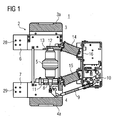
- eine Querschnittsansicht eines erfindungsgemäßen Leistungsschalters;
- Figur 2
- eine Detailansicht im Bereich des Festkontaktes; und
- Figur 3
- eine Detailansicht im Bereich des Bewegkontaktes.
-
Figur 1 zeigt einen Hochstromschalter als Leistungsschalter für Hochstromanwendungen in einer Querschnittsansicht. Der Leistungsschalter 1 umfasst drei Poleinheiten für die drei Phasen eines zu schaltenden Wechselstromes, von denen figürlich dargestellt nur eine Poleinheit mit 2 bezeichnet ist. Die Poleinheit 2 umfasst einen Polkopf 3 sowie einen Polträger 4, zwischen denen ein Kontaktsystem 5 in Form einer Vakuumschaltröhre 5 zum Schalten eines Stromes zwischen einer ersten Stromschiene 6 und einer zweiten Stromschiene 7 der Poleinheit 2 angeordnet ist. Ein Bewegkontakt 8 der Vakuumschaltröhre 5 ist über ein Antriebsgestänge 9 mit einer Antriebseinheit 10 des Leistungsschalters gekoppelt, wobei die Antriebseinheit 10 zum Einleiten einer Schaltbewegung in den Bewegkontakt 8 des Kontaktsystems 5 ausgebildet ist. Der Bewegkontakt 8 ist mittels zweiten Anschlussmitteln 11 mit der zweiten Stromschiene 7 verbunden. Ein Festkontakt 12 der Vakuumschaltröhre 5 ist über erste Anschlussmittel 13 mit der ersten Stromschiene 6 elektrisch leitend verbunden. Die Poleinheit ist mittels Stützeinrichtungen 14 und 15 an einer Haltewand 16 des Leistungsschalters 1 befestigt. -
Figur 2 zeigt eine Querschnittsansicht einer Detaildarstellung im Bereich des Festkontaktes 12 der Vakuumschaltröhre 5. Der Festkontakt 12 der Vakuumschaltröhre 5 in Form eines zylindrischen Bolzens ist mit dem ersten Anschlussmittel 13 in Form einer kupferförmigen Platte, welche eine dem Bolzen des Festkontaktes 12 entsprechende Ausnehmung aufweist, im Bereich 17 umlaufend elektronenstrahlverschweißt, wodurch eine kraft- und stoffschlüssige Verbindung zwischen dem Festkontakt 12 und dem zweiten Anschlussmittel 13 ausgebildet ist. Das zweite Anschlussmittel 13 ist des Weiteren mit den ersten Stromschienen 6 im Bereich 18 ebenfalls elektronenstrahlverschweißt. Zur Stabilisierung ist zwischen den Stromschienen ein Aluminiumabstandshalter 19 angeordnet. -
Figur 3 zeigt eine Detailansicht im Bereich des Bewegkontaktes der Vakuumschaltröhre 5 aus derFigur 1 . Der Bewegkontakt 8 ist an seinem verjüngten Ende 20 im Bereich 21 umlaufend mit dem zweiten Anschlussmittel 11 in Form einer kupferförmigen Platte mit einer dem Bolzen 20 des Bewegkontaktes 8 entsprechenden Ausnehmung elektronenstrahlverschweißt. Flexible Stromleiter 22 und 23 sind in den Bereichen 24 mit dem zweiten Anschlussmittel 11 ebenfalls elektronenstrahlverschweißt und bei 26 und 27 mit der zweiten Stromschiene 7 elektronenstrahlverschweißt. Durch die kraft- und stoffschlüssige Verbindung in den Bereichen 21, 24, 25, 26 und 27 sind im Bereich der flexiblen Stromleiter 22 und 23 und des Bewegkontaktes 8 keine weiteren Verschraubungen als Befestigungsmittel notwendig. - Wie aus der
Figur 1 ersichtlich, sind der Polkopf 3 und der Polträger 4 mit Kühlkörpern 3a bzw. 4a versehen, welche zur Abfuhr der durch die hohen Ströme im Bereich des Festkontaktes 12 bzw. des Bewegkontaktes 8 erzeugten Wärme dienen. Zum Anschluss des Hochstromschalters 1 sind an der ersten Stromschiene 6 Befestigungsmittel 28 und an der zweiten Stromschiene 7 Befestigungsmittel 29 vorgesehen, welche jeweils zur Verschraubung der ersten Stromschiene 6 und der zweiten Stromschiene 7 beispielsweise mit Sammelschienen einer Schaltanlage vorgesehen sind. Durch die Kühlkörper 3a und 4a wird die Temperatur der stromführenden Teile derartig abgesenkt, dass im Bereich der Verschraubungen 28 bzw. 29 die Temperatur im erforderlichen Bereich von weniger als 65 bis 75 Grad Kelvin über der Umgebungstemperatur liegt. -
- 1
- Leistungsschalter
- 2
- Poleinheit
- 3
- Polkopf
- 4
- Polträger
- 5
- Vakuumschaltröhre
- 6
- Erste Stromschiene
- 7
- Zweite Stromschiene
- 8
- Bewegkontakt
- 9
- Antriebsgestänge
- 10
- Antriebseinheit
- 11
- Zweite Anschlussmittel
- 12
- Festkontakt
- 13
- Erste Anschlussmittel
- 14, 15
- Stützeinrichtungen
- 16,
- Haltewand
- 17, 18
- Verbindungsbereiche
- 19
- Stabilisierungselement
- 20
- Bewegkontaktbolzen
- 21
- Verbindungsbereiche
- 22, 23
- Flexible Stromleiter
- 24, 25, 26, 27
- Verbindungsbereiche
- 28, 29
- Befestigungsmittel
- 3a, 4a
- Kühlkörper
Claims (3)
- Leistungsschalter, insbesondere Hochstromschalter mit mindestens einer Poleinheit (2) mit einem Polkopf (3) und einem Polträger (4) und einer dazwischen angeordneten Vakuumschaltröhre (5) mit einem Festkontakt (12) und einem Bewegkontakt (8, 20), wobei der Festkontakt (12) über ein erstes Anschlussmittel (13) mit einer ersten Stromschiene (6) der Poleinheit (2) und der Bewegkontakt (8) über ein zweites Anschlussmittel (11) mit einer zweiten Stromschiene (7) der Poleinheit (2) verbunden sind,
dadurch gekennzeichnet, dass
die ersten Anschlussmittel (13) mit der ersten Stromschiene (6) und dem Festkontakt (12) sowie die zweiten Anschlussmittel (11) mit der zweiten Stromschiene (7) und dem Bewegkontakt (8, 20) verschweißt sind. - Leistungsschalter nach Anspruch 1,
dadurch gekennzeichnet, dass
die zweite Stromschiene (7) einen flexiblen Stromleiter (22, 23) aufweist und mit dem flexiblen Stromleiter (22, 23) und dem zweiten Anschlussmittel (11) verschweißt ist. - Leistungsschalter nach Anspruch 1 oder 2,
dadurch gekennzeichnet, dass
die Anschlussmittel (11, 13) elektronenstrahlverschweißt sind.
Applications Claiming Priority (2)
| Application Number | Priority Date | Filing Date | Title |
|---|---|---|---|
| DE202006007973U DE202006007973U1 (de) | 2006-05-10 | 2006-05-10 | Leistungsschalter, insbesondere Hochstromschalter |
| PCT/EP2007/054494 WO2007128831A1 (de) | 2006-05-10 | 2007-05-09 | Leistungsschalter, insbesondere hochstromschalter |
Publications (2)
| Publication Number | Publication Date |
|---|---|
| EP2016601A1 EP2016601A1 (de) | 2009-01-21 |
| EP2016601B1 true EP2016601B1 (de) | 2010-06-30 |
Family
ID=36848650
Family Applications (1)
| Application Number | Title | Priority Date | Filing Date |
|---|---|---|---|
| EP07728946A Active EP2016601B1 (de) | 2006-05-10 | 2007-05-09 | Leistungsschalter, insbesondere hochstromschalter |
Country Status (10)
| Country | Link |
|---|---|
| US (1) | US20100059479A1 (de) |
| EP (1) | EP2016601B1 (de) |
| JP (1) | JP2009536429A (de) |
| KR (1) | KR20090014291A (de) |
| CN (2) | CN201015105Y (de) |
| AT (1) | ATE472811T1 (de) |
| CA (1) | CA2652047A1 (de) |
| DE (2) | DE202006007973U1 (de) |
| RU (1) | RU2008148581A (de) |
| WO (1) | WO2007128831A1 (de) |
Families Citing this family (7)
| Publication number | Priority date | Publication date | Assignee | Title |
|---|---|---|---|---|
| ATE504931T1 (de) * | 2007-12-07 | 2011-04-15 | Abb Technology Ag | Schaltgetriebeanordnung mit niedriger, mittlerer oder hoher spannung und mit mindestens einem beweglichen kontakt |
| GB2511569B (en) | 2013-03-08 | 2015-05-06 | Christopher John Stanton | Improved switch and associated methods |
| US9330867B2 (en) * | 2014-05-13 | 2016-05-03 | Eaton Corporation | Vacuum switching apparatus, and electrode extension assembly and associated assembly method therefor |
| US9767978B1 (en) * | 2016-05-17 | 2017-09-19 | Eaton Corporation | Medium voltage breaker conductor with an electrically efficient contour |
| DE102020210183A1 (de) * | 2020-08-12 | 2022-02-17 | Siemens Energy Global GmbH & Co. KG | Hochspannungsleistungsschalter und Verfahren zum Herstellen eines Hochspannungsleistungsschalters |
| DE102020211514B4 (de) * | 2020-09-14 | 2024-02-01 | Siemens Energy Global GmbH & Co. KG | Hochspannungsleistungsschalter mit Schrumpfverbindung und Verfahren zum Herstellen des Hochspannungsleistungsschalters |
| DE102020211516A1 (de) * | 2020-09-14 | 2022-03-17 | Siemens Energy Global GmbH & Co. KG | Hochspannungsleistungsschalter mit Kontakthülse und Verfahren zum Herstellen des Hochspannungsleistungsschalters |
Family Cites Families (6)
| Publication number | Priority date | Publication date | Assignee | Title |
|---|---|---|---|---|
| FR2339243A1 (fr) * | 1976-01-26 | 1977-08-19 | Merlin Gerin | Conducteur de connexion flexible |
| US4153827A (en) * | 1976-01-26 | 1979-05-08 | Merlin Gerin | Magnetic blow-out arc extinguishing device |
| DE19636237A1 (de) * | 1996-06-21 | 1998-01-02 | Siemens Ag | Schaltkontaktsystem eines Niederspannungs-Leistungsschalters mit biegsamen Leitern |
| DE19712182A1 (de) * | 1997-03-22 | 1998-09-24 | Abb Patent Gmbh | Vakuumkammer |
| DE19819163A1 (de) * | 1998-04-24 | 1999-10-28 | Siemens Ag | Schaltungskontaktsystem eines Niederspannungs-Leistungsschalters mit flexiblen Leiterseilen |
| US6444939B1 (en) * | 2000-05-09 | 2002-09-03 | Eaton Corporation | Vacuum switch operating mechanism including laminated flexible shunt connector |
-
2006
- 2006-05-10 DE DE202006007973U patent/DE202006007973U1/de not_active Expired - Lifetime
- 2006-08-08 CN CNU2006201647734U patent/CN201015105Y/zh not_active Expired - Lifetime
-
2007
- 2007-05-09 CN CNA2007800155886A patent/CN101432832A/zh active Pending
- 2007-05-09 EP EP07728946A patent/EP2016601B1/de active Active
- 2007-05-09 WO PCT/EP2007/054494 patent/WO2007128831A1/de active Application Filing
- 2007-05-09 JP JP2009508384A patent/JP2009536429A/ja not_active Withdrawn
- 2007-05-09 RU RU2008148581/09A patent/RU2008148581A/ru not_active Application Discontinuation
- 2007-05-09 US US12/300,130 patent/US20100059479A1/en not_active Abandoned
- 2007-05-09 DE DE502007004262T patent/DE502007004262D1/de active Active
- 2007-05-09 KR KR1020087030037A patent/KR20090014291A/ko not_active Application Discontinuation
- 2007-05-09 AT AT07728946T patent/ATE472811T1/de active
- 2007-05-09 CA CA002652047A patent/CA2652047A1/en not_active Abandoned
Also Published As
| Publication number | Publication date |
|---|---|
| WO2007128831A1 (de) | 2007-11-15 |
| EP2016601A1 (de) | 2009-01-21 |
| DE202006007973U1 (de) | 2006-08-03 |
| CN101432832A (zh) | 2009-05-13 |
| US20100059479A1 (en) | 2010-03-11 |
| DE502007004262D1 (de) | 2010-08-12 |
| JP2009536429A (ja) | 2009-10-08 |
| CN201015105Y (zh) | 2008-01-30 |
| KR20090014291A (ko) | 2009-02-09 |
| RU2008148581A (ru) | 2010-06-20 |
| ATE472811T1 (de) | 2010-07-15 |
| CA2652047A1 (en) | 2007-11-15 |
Similar Documents
| Publication | Publication Date | Title |
|---|---|---|
| EP1719225B1 (de) | Gekapselte gasisolierte schaltanlage | |
| EP2016601B1 (de) | Leistungsschalter, insbesondere hochstromschalter | |
| EP0688071B2 (de) | Metallgekapselte gasisolierte Schaltanlage | |
| EP1318547B1 (de) | Leistungshalbleiter-Modul | |
| EP1444761B1 (de) | Mehrphasiges sammelschienensystem | |
| DE102015105347A1 (de) | Anordnung mit einem leitstungselektronischen Bauteil und mit einer Gleichspannungsverschienung | |
| DE19942915A1 (de) | Leistungshalbleitermodul | |
| DE2809851C2 (de) | Metallgekapselte mehrphasige Schaltanlage für hohe Spannungen | |
| EP2923422B1 (de) | Stromschienenanordnung und verfahren zur herstellung einer stromschienenanordnung | |
| EP1593137A1 (de) | Installationsgerät und installationsbaugruppe mit installationsgerät | |
| EP3557614A1 (de) | Leistungsmodul mit einem leistungselektronischen bauelement auf einer substratplatte und leistungselektronische schaltung mit einem solchen leistungsmodul | |
| EP1249910A2 (de) | Hochspannungs-Leistungsschalter für eine druckgasisolierte Schaltanlage | |
| EP3300470A1 (de) | Umrichter | |
| DE3833718A1 (de) | Gasisolierte schaltvorrichtung | |
| EP0678953B1 (de) | Kabelanschluss für eine metallgekapselte gasisolierte Hochspannungsschaltanlage | |
| EP3208925B1 (de) | Umrichter | |
| EP2467864B1 (de) | Halteelement für eine schaltanlage | |
| EP3469611B1 (de) | Kontaktanordnung für ein hochspannungs-schaltgerät sowie dessen verwendung und herstellung | |
| EP3176822B1 (de) | Elektrisch und thermisch effiziente leistungsbrücke | |
| WO2018153584A1 (de) | Schalteranordnung mit zwei trennschaltern und einem leistungsschalter | |
| WO2011020511A1 (de) | Verbindungsmittel | |
| DE102006053376A1 (de) | Elektrische Hochspannugnsanlage | |
| EP3753109B1 (de) | Schaltungsanordnung und stromrichtermodul mit in reihe geschalteten schalterbaugruppen | |
| DE102006008480B4 (de) | Trenner | |
| DE10260371A1 (de) | Niederspannungs-Leistungsschalter |
Legal Events
| Date | Code | Title | Description |
|---|---|---|---|
| PUAI | Public reference made under article 153(3) epc to a published international application that has entered the european phase |
Free format text: ORIGINAL CODE: 0009012 |
|
| 17P | Request for examination filed |
Effective date: 20081020 |
|
| AK | Designated contracting states |
Kind code of ref document: A1 Designated state(s): AT BE BG CH CY CZ DE DK EE ES FI FR GB GR HU IE IS IT LI LT LU LV MC MT NL PL PT RO SE SI SK TR |
|
| AX | Request for extension of the european patent |
Extension state: AL BA HR MK RS |
|
| RIN1 | Information on inventor provided before grant (corrected) |
Inventor name: RUETHNICK, CLEMENS Inventor name: KURTH, RALF-PETER |
|
| GRAP | Despatch of communication of intention to grant a patent |
Free format text: ORIGINAL CODE: EPIDOSNIGR1 |
|
| GRAS | Grant fee paid |
Free format text: ORIGINAL CODE: EPIDOSNIGR3 |
|
| GRAA | (expected) grant |
Free format text: ORIGINAL CODE: 0009210 |
|
| AK | Designated contracting states |
Kind code of ref document: B1 Designated state(s): AT BE BG CH CY CZ DE DK EE ES FI FR GB GR HU IE IS IT LI LT LU LV MC MT NL PL PT RO SE SI SK TR |
|
| REG | Reference to a national code |
Ref country code: CH Ref legal event code: EP Ref country code: GB Ref legal event code: FG4D Free format text: NOT ENGLISH |
|
| REG | Reference to a national code |
Ref country code: IE Ref legal event code: FG4D Free format text: LANGUAGE OF EP DOCUMENT: GERMAN |
|
| REF | Corresponds to: |
Ref document number: 502007004262 Country of ref document: DE Date of ref document: 20100812 Kind code of ref document: P |
|
| REG | Reference to a national code |
Ref country code: SE Ref legal event code: TRGR |
|
| REG | Reference to a national code |
Ref country code: NL Ref legal event code: VDEP Effective date: 20100630 |
|
| PG25 | Lapsed in a contracting state [announced via postgrant information from national office to epo] |
Ref country code: LT Free format text: LAPSE BECAUSE OF FAILURE TO SUBMIT A TRANSLATION OF THE DESCRIPTION OR TO PAY THE FEE WITHIN THE PRESCRIBED TIME-LIMIT Effective date: 20100630 |
|
| LTIE | Lt: invalidation of european patent or patent extension |
Effective date: 20100630 |
|
| PG25 | Lapsed in a contracting state [announced via postgrant information from national office to epo] |
Ref country code: SI Free format text: LAPSE BECAUSE OF FAILURE TO SUBMIT A TRANSLATION OF THE DESCRIPTION OR TO PAY THE FEE WITHIN THE PRESCRIBED TIME-LIMIT Effective date: 20100630 Ref country code: FI Free format text: LAPSE BECAUSE OF FAILURE TO SUBMIT A TRANSLATION OF THE DESCRIPTION OR TO PAY THE FEE WITHIN THE PRESCRIBED TIME-LIMIT Effective date: 20100630 Ref country code: LV Free format text: LAPSE BECAUSE OF FAILURE TO SUBMIT A TRANSLATION OF THE DESCRIPTION OR TO PAY THE FEE WITHIN THE PRESCRIBED TIME-LIMIT Effective date: 20100630 |
|
| PG25 | Lapsed in a contracting state [announced via postgrant information from national office to epo] |
Ref country code: PL Free format text: LAPSE BECAUSE OF FAILURE TO SUBMIT A TRANSLATION OF THE DESCRIPTION OR TO PAY THE FEE WITHIN THE PRESCRIBED TIME-LIMIT Effective date: 20100630 |
|
| PG25 | Lapsed in a contracting state [announced via postgrant information from national office to epo] |
Ref country code: NL Free format text: LAPSE BECAUSE OF FAILURE TO SUBMIT A TRANSLATION OF THE DESCRIPTION OR TO PAY THE FEE WITHIN THE PRESCRIBED TIME-LIMIT Effective date: 20100630 Ref country code: EE Free format text: LAPSE BECAUSE OF FAILURE TO SUBMIT A TRANSLATION OF THE DESCRIPTION OR TO PAY THE FEE WITHIN THE PRESCRIBED TIME-LIMIT Effective date: 20100630 |
|
| REG | Reference to a national code |
Ref country code: IE Ref legal event code: FD4D |
|
| PG25 | Lapsed in a contracting state [announced via postgrant information from national office to epo] |
Ref country code: PT Free format text: LAPSE BECAUSE OF FAILURE TO SUBMIT A TRANSLATION OF THE DESCRIPTION OR TO PAY THE FEE WITHIN THE PRESCRIBED TIME-LIMIT Effective date: 20101102 Ref country code: RO Free format text: LAPSE BECAUSE OF FAILURE TO SUBMIT A TRANSLATION OF THE DESCRIPTION OR TO PAY THE FEE WITHIN THE PRESCRIBED TIME-LIMIT Effective date: 20100630 Ref country code: SK Free format text: LAPSE BECAUSE OF FAILURE TO SUBMIT A TRANSLATION OF THE DESCRIPTION OR TO PAY THE FEE WITHIN THE PRESCRIBED TIME-LIMIT Effective date: 20100630 Ref country code: CY Free format text: LAPSE BECAUSE OF FAILURE TO SUBMIT A TRANSLATION OF THE DESCRIPTION OR TO PAY THE FEE WITHIN THE PRESCRIBED TIME-LIMIT Effective date: 20100630 Ref country code: CZ Free format text: LAPSE BECAUSE OF FAILURE TO SUBMIT A TRANSLATION OF THE DESCRIPTION OR TO PAY THE FEE WITHIN THE PRESCRIBED TIME-LIMIT Effective date: 20100630 Ref country code: IS Free format text: LAPSE BECAUSE OF FAILURE TO SUBMIT A TRANSLATION OF THE DESCRIPTION OR TO PAY THE FEE WITHIN THE PRESCRIBED TIME-LIMIT Effective date: 20101030 |
|
| PG25 | Lapsed in a contracting state [announced via postgrant information from national office to epo] |
Ref country code: DK Free format text: LAPSE BECAUSE OF FAILURE TO SUBMIT A TRANSLATION OF THE DESCRIPTION OR TO PAY THE FEE WITHIN THE PRESCRIBED TIME-LIMIT Effective date: 20100630 Ref country code: IE Free format text: LAPSE BECAUSE OF FAILURE TO SUBMIT A TRANSLATION OF THE DESCRIPTION OR TO PAY THE FEE WITHIN THE PRESCRIBED TIME-LIMIT Effective date: 20100630 |
|
| PLBE | No opposition filed within time limit |
Free format text: ORIGINAL CODE: 0009261 |
|
| STAA | Information on the status of an ep patent application or granted ep patent |
Free format text: STATUS: NO OPPOSITION FILED WITHIN TIME LIMIT |
|
| PG25 | Lapsed in a contracting state [announced via postgrant information from national office to epo] |
Ref country code: GR Free format text: LAPSE BECAUSE OF FAILURE TO SUBMIT A TRANSLATION OF THE DESCRIPTION OR TO PAY THE FEE WITHIN THE PRESCRIBED TIME-LIMIT Effective date: 20101001 |
|
| 26N | No opposition filed |
Effective date: 20110331 |
|
| PG25 | Lapsed in a contracting state [announced via postgrant information from national office to epo] |
Ref country code: ES Free format text: LAPSE BECAUSE OF FAILURE TO SUBMIT A TRANSLATION OF THE DESCRIPTION OR TO PAY THE FEE WITHIN THE PRESCRIBED TIME-LIMIT Effective date: 20101011 |
|
| REG | Reference to a national code |
Ref country code: DE Ref legal event code: R097 Ref document number: 502007004262 Country of ref document: DE Effective date: 20110330 |
|
| BERE | Be: lapsed |
Owner name: SIEMENS A.G. Effective date: 20110531 |
|
| PG25 | Lapsed in a contracting state [announced via postgrant information from national office to epo] |
Ref country code: MT Free format text: LAPSE BECAUSE OF FAILURE TO SUBMIT A TRANSLATION OF THE DESCRIPTION OR TO PAY THE FEE WITHIN THE PRESCRIBED TIME-LIMIT Effective date: 20100630 Ref country code: MC Free format text: LAPSE BECAUSE OF NON-PAYMENT OF DUE FEES Effective date: 20110531 |
|
| REG | Reference to a national code |
Ref country code: CH Ref legal event code: PL |
|
| PG25 | Lapsed in a contracting state [announced via postgrant information from national office to epo] |
Ref country code: CH Free format text: LAPSE BECAUSE OF NON-PAYMENT OF DUE FEES Effective date: 20110531 Ref country code: LI Free format text: LAPSE BECAUSE OF NON-PAYMENT OF DUE FEES Effective date: 20110531 |
|
| PG25 | Lapsed in a contracting state [announced via postgrant information from national office to epo] |
Ref country code: BE Free format text: LAPSE BECAUSE OF NON-PAYMENT OF DUE FEES Effective date: 20110531 |
|
| PG25 | Lapsed in a contracting state [announced via postgrant information from national office to epo] |
Ref country code: LU Free format text: LAPSE BECAUSE OF NON-PAYMENT OF DUE FEES Effective date: 20110509 |
|
| REG | Reference to a national code |
Ref country code: AT Ref legal event code: MM01 Ref document number: 472811 Country of ref document: AT Kind code of ref document: T Effective date: 20120509 |
|
| PG25 | Lapsed in a contracting state [announced via postgrant information from national office to epo] |
Ref country code: AT Free format text: LAPSE BECAUSE OF NON-PAYMENT OF DUE FEES Effective date: 20120509 |
|
| PG25 | Lapsed in a contracting state [announced via postgrant information from national office to epo] |
Ref country code: BG Free format text: LAPSE BECAUSE OF FAILURE TO SUBMIT A TRANSLATION OF THE DESCRIPTION OR TO PAY THE FEE WITHIN THE PRESCRIBED TIME-LIMIT Effective date: 20100930 |
|
| PG25 | Lapsed in a contracting state [announced via postgrant information from national office to epo] |
Ref country code: HU Free format text: LAPSE BECAUSE OF FAILURE TO SUBMIT A TRANSLATION OF THE DESCRIPTION OR TO PAY THE FEE WITHIN THE PRESCRIBED TIME-LIMIT Effective date: 20100630 |
|
| REG | Reference to a national code |
Ref country code: FR Ref legal event code: PLFP Year of fee payment: 10 |
|
| PGFP | Annual fee paid to national office [announced via postgrant information from national office to epo] |
Ref country code: GB Payment date: 20160512 Year of fee payment: 10 |
|
| REG | Reference to a national code |
Ref country code: FR Ref legal event code: PLFP Year of fee payment: 11 |
|
| GBPC | Gb: european patent ceased through non-payment of renewal fee |
Effective date: 20170509 |
|
| PG25 | Lapsed in a contracting state [announced via postgrant information from national office to epo] |
Ref country code: GB Free format text: LAPSE BECAUSE OF NON-PAYMENT OF DUE FEES Effective date: 20170509 |
|
| REG | Reference to a national code |
Ref country code: FR Ref legal event code: PLFP Year of fee payment: 12 |
|
| PGFP | Annual fee paid to national office [announced via postgrant information from national office to epo] |
Ref country code: IT Payment date: 20230523 Year of fee payment: 17 Ref country code: FR Payment date: 20230515 Year of fee payment: 17 Ref country code: DE Payment date: 20220620 Year of fee payment: 17 |
|
| PGFP | Annual fee paid to national office [announced via postgrant information from national office to epo] |
Ref country code: TR Payment date: 20230508 Year of fee payment: 17 Ref country code: SE Payment date: 20230508 Year of fee payment: 17 |