EP2016237B1 - Élément d'étanchéite pour un panneau de construction léger - Google Patents
Élément d'étanchéite pour un panneau de construction léger Download PDFInfo
- Publication number
- EP2016237B1 EP2016237B1 EP07728856.1A EP07728856A EP2016237B1 EP 2016237 B1 EP2016237 B1 EP 2016237B1 EP 07728856 A EP07728856 A EP 07728856A EP 2016237 B1 EP2016237 B1 EP 2016237B1
- Authority
- EP
- European Patent Office
- Prior art keywords
- lightweight board
- sealing
- middle layer
- cover plates
- section
- Prior art date
- Legal status (The legal status is an assumption and is not a legal conclusion. Google has not performed a legal analysis and makes no representation as to the accuracy of the status listed.)
- Not-in-force
Links
- 238000007789 sealing Methods 0.000 title claims description 117
- 239000000463 material Substances 0.000 claims description 15
- 239000000565 sealant Substances 0.000 claims description 11
- 239000002023 wood Substances 0.000 claims description 11
- 239000011111 cardboard Substances 0.000 claims description 9
- 239000002390 adhesive tape Substances 0.000 claims description 8
- 150000001875 compounds Chemical class 0.000 claims description 4
- 239000013013 elastic material Substances 0.000 claims description 4
- 239000002184 metal Substances 0.000 claims description 4
- 229910052751 metal Inorganic materials 0.000 claims description 4
- 239000004952 Polyamide Substances 0.000 claims description 2
- 239000011248 coating agent Substances 0.000 claims description 2
- 238000000576 coating method Methods 0.000 claims description 2
- 239000011888 foil Substances 0.000 claims description 2
- 229920002647 polyamide Polymers 0.000 claims description 2
- 238000001125 extrusion Methods 0.000 claims 1
- 239000003292 glue Substances 0.000 claims 1
- 230000001070 adhesive effect Effects 0.000 description 15
- 239000000853 adhesive Substances 0.000 description 12
- 238000004026 adhesive bonding Methods 0.000 description 3
- 238000010276 construction Methods 0.000 description 3
- 239000011094 fiberboard Substances 0.000 description 3
- 230000008901 benefit Effects 0.000 description 2
- 239000011093 chipboard Substances 0.000 description 2
- 238000005520 cutting process Methods 0.000 description 2
- 238000005034 decoration Methods 0.000 description 2
- 238000003780 insertion Methods 0.000 description 2
- 230000037431 insertion Effects 0.000 description 2
- 238000009434 installation Methods 0.000 description 2
- 238000004519 manufacturing process Methods 0.000 description 2
- 238000000034 method Methods 0.000 description 2
- 238000003801 milling Methods 0.000 description 2
- 210000001331 nose Anatomy 0.000 description 2
- 241000894006 Bacteria Species 0.000 description 1
- 239000004640 Melamine resin Substances 0.000 description 1
- 229920000877 Melamine resin Polymers 0.000 description 1
- 240000007182 Ochroma pyramidale Species 0.000 description 1
- 230000003213 activating effect Effects 0.000 description 1
- 230000004913 activation Effects 0.000 description 1
- 230000002411 adverse Effects 0.000 description 1
- 229910052782 aluminium Inorganic materials 0.000 description 1
- XAGFODPZIPBFFR-UHFFFAOYSA-N aluminium Chemical compound [Al] XAGFODPZIPBFFR-UHFFFAOYSA-N 0.000 description 1
- 210000000078 claw Anatomy 0.000 description 1
- 239000002131 composite material Substances 0.000 description 1
- 239000000356 contaminant Substances 0.000 description 1
- 238000009826 distribution Methods 0.000 description 1
- 230000000694 effects Effects 0.000 description 1
- 239000006260 foam Substances 0.000 description 1
- 238000010438 heat treatment Methods 0.000 description 1
- 244000144980 herd Species 0.000 description 1
- 229910052500 inorganic mineral Inorganic materials 0.000 description 1
- 238000009413 insulation Methods 0.000 description 1
- 239000011707 mineral Substances 0.000 description 1
- 239000003973 paint Substances 0.000 description 1
- 238000010422 painting Methods 0.000 description 1
- 239000011087 paperboard Substances 0.000 description 1
- 230000000149 penetrating effect Effects 0.000 description 1
- 239000004033 plastic Substances 0.000 description 1
- 239000004800 polyvinyl chloride Substances 0.000 description 1
- 238000003825 pressing Methods 0.000 description 1
- 230000001681 protective effect Effects 0.000 description 1
- 239000007787 solid Substances 0.000 description 1
- 241000894007 species Species 0.000 description 1
- 230000008961 swelling Effects 0.000 description 1
- 239000012815 thermoplastic material Substances 0.000 description 1
- 210000002268 wool Anatomy 0.000 description 1
Images


Classifications
-
- E—FIXED CONSTRUCTIONS
- E04—BUILDING
- E04C—STRUCTURAL ELEMENTS; BUILDING MATERIALS
- E04C2/00—Building elements of relatively thin form for the construction of parts of buildings, e.g. sheet materials, slabs, or panels
- E04C2/30—Building elements of relatively thin form for the construction of parts of buildings, e.g. sheet materials, slabs, or panels characterised by the shape or structure
- E04C2/34—Building elements of relatively thin form for the construction of parts of buildings, e.g. sheet materials, slabs, or panels characterised by the shape or structure composed of two or more spaced sheet-like parts
- E04C2/36—Building elements of relatively thin form for the construction of parts of buildings, e.g. sheet materials, slabs, or panels characterised by the shape or structure composed of two or more spaced sheet-like parts spaced apart by transversely-placed strip material, e.g. honeycomb panels
- E04C2/365—Building elements of relatively thin form for the construction of parts of buildings, e.g. sheet materials, slabs, or panels characterised by the shape or structure composed of two or more spaced sheet-like parts spaced apart by transversely-placed strip material, e.g. honeycomb panels by honeycomb structures
-
- B—PERFORMING OPERATIONS; TRANSPORTING
- B27—WORKING OR PRESERVING WOOD OR SIMILAR MATERIAL; NAILING OR STAPLING MACHINES IN GENERAL
- B27D—WORKING VENEER OR PLYWOOD
- B27D5/00—Other working of veneer or plywood specially adapted to veneer or plywood
- B27D5/003—Other working of veneer or plywood specially adapted to veneer or plywood securing a veneer strip to a panel edge
Definitions
- the invention relates to a lightweight board according to the preamble of claim 1.
- a lightweight board is known for example from the DE 195 06 158 A1 , Furthermore, the invention relates to a use of an element for covering a narrow surface of a lightweight building panel according to claim 14.
- Lightweight panels are well known in the art. Also in furniture and interior design, these are used for a long time in a variety of ways. The main field of application was and is the door construction here. So it is especially in room doors, which are therefore subject to low requirements in terms of heat and sound insulation, usually a frame member with a honeycomb core on both sides to plank and this then continue to process the corresponding holes, millings, etc. to a door element.
- the manufacturer of furniture does not need to manufacture lightweight panels today, as was the case earlier.
- a frame had to be made, possibly with several crossbars, on which the top layers were then applied and which had to accommodate the various fittings.
- cover layers lightweight fiber boards, mineral insulating wool, cardboard honeycomb or the like were introduced. This gave the item more compactness and possibly improved stability.
- the outer layers also had to be elaborately surface-treated in separate operations. For example, veneered or otherwise coated hardboards were used as cover layers, and the finished element can only be given its final surface by final painting.
- cover plates Today, lightweight panels are increasingly being manufactured industrially.
- a light middle layer is provided with cover plates, usually by gluing, so that a large-format, frameless composite arises.
- cover plates mostly from a wood material such as chipboard or fiberboard used.
- the plates used may already be coated, that is to say be provided with a laminate, a paint, a pressure with a seal, a melamine resin layer, a veneer, etc.
- cardboard honeycomb or foam boards are preferred.
- Honeycomb materials made of materials other than paper or cardboard may also be useful for certain purposes. For example, the thinnest sheet materials or even thin-walled metal such as aluminum can be used.
- middle layer of lightweight wood materials such as appropriate chipboard or fiberboard or solid wood of low density, such as balsa wood
- wood species are used for that, although not particularly low weight, but are well available and can be easily edited with cutting tools.
- the plates thus produced are then divided into the desired size. Depending on the intended use of the resulting elements, these are then provided with edges or an at least partially encircling frame is subsequently introduced. This is done by milling the edge area and subsequent gluing a frame profile, which in turn consists mostly of a wood material.
- Cutouts are necessary, for example, when using a lightweight board as a kitchen worktop to accommodate a sink or a stove top.
- the invention is therefore based on the technical problem of providing measures that allow protection of narrow surfaces and middle layers in a simple and individual way.
- the DE 296 17 862 U1 relates to a frame for producing a wall and / or door element, which may be provided on both sides with a cover plate made of metal, plastic or laminate.
- the frame extends exclusively between the cover plates and can thus be regarded as covering the narrow surface in the region between the cover plates.
- a lightweight board which is formed of two cover plates and a middle layer arranged therebetween, with at least one narrow surface and with a narrow surface covering element, with an outer Section, wherein the outer portion has a height which corresponds at least to the distance of the side facing away from the central position surfaces of the cover plates, and having an inner portion, wherein the opposite sides of the portion have a distance which at least the distance of the central position facing Surface of the cover plates corresponds, wherein the outer portion is formed integrally with the inner portion, wherein the element is a sealing member having at least one sealing surface for sealing at least a narrow surface of a cover plate and / or a middle layer of the lightweight board, the derar t is formed, that in the assembled state, a sealing of the narrow surface of the cover plate and / or the middle layer of the lightweight board allows, wherein the two cover plates are formed of a wood material, wherein the central layer
- the invention has thus recognized that such a lightweight board with a sealing element in a particularly simple way individually protection, in particular a seal that allows exposed by the neckline narrow surfaces.
- the sealing element can be inserted with its inner portion between the cover plates, wherein previously in the Einsteck Scheme the central layer is recessed, so that the outer portion with the narrow surfaces of the cover plates in contact and this, in particular by the outer portion performs a sealing function protects , Especially when using a lightweight board as a kitchen countertop arise manifold situations in which contaminants with the narrow surfaces and / or the middle layer can come into contact, which can lead to swelling of the polluted areas and / or herd of bacteria. Even when using a lightweight board in other applications, the narrow surfaces and / or the middle layer, in particular by moisture, deform adversely, discolor or develop undesirable properties in any other way.
- the inner section projects in the direction of the central position relative to the outer section. In this way, the inner portion can be inserted during assembly between the cover plates, which increases the sealing effect and stability.
- the inner section has at least one projection, preferably two projections, which projects in the direction of the central position relative to the outer section.
- at least one of the projections have a latching nose, which cooperates with a corresponding recess in the cover plate.
- the depressions on the inside of the Cover plate provided and the locking lugs are away from each other. This forms a clip connection which allows for easy assembly and disassembly of the sealing element.
- the depressions are provided on the outer side of the cover plate and the latching noses face each other.
- the height of the outer portion corresponds to the distance of the opposite sides of the inner portion.
- the at least one projection is part of a spring profile which can cooperate with a corresponding groove profile in the cover plate. It is also conceivable that the at least one projection is part of a groove profile, which can cooperate with a corresponding spring profile in the cover plate.
- a groove / spring connection also provides a simple way to assemble and disassemble the sealing element.
- the sections can be made of an elastic material, an outer portion is given, which is particularly good for round cutouts or cutouts with rounded edges on the narrow surfaces applies and thus seals very well.
- the inner portion can thereby be used non-positively in the recess of the middle layer and between the cover plates.
- the elasticity can be chosen such that a deformation of the inner portion does not lead to a pressing apart of the cover plates.
- the sections may also have thermal resistance. This is advantageous if the sealing element comes into contact with heating elements which are to be arranged in the cutout of the lightweight building board. Such an element can be stovetops.
- the thermal resistance may be provided up to a temperature of 150 ° C., in particular up to 100 ° C., so that the sealing element does not disadvantageously deform up to this temperature.
- all elastic materials can be used. It may be a thermoplastic material or PVC or polyamide.
- a particularly preferred embodiment is characterized in that the sections together have a T-shaped cross-section.
- a sealing element designed in this way allows a simple insertion into the recess of the middle layer and sealing of the narrow surfaces.
- At least one section at least one sealing surface for sealing at least one element of the lightweight building board, in particular a narrow surface of a Cover plate, a cover plate and / or middle layer
- the tightness and protection of the narrow surfaces and / or center layer can be further improved.
- for sealing what can be done by gluing the sealing surfaces with the narrow surfaces and / or the cover plates in the region of the central position and the middle layer itself, find any known adhesive use.
- a sealant has the advantage that it does not develop any appreciable adhesive effect after setting.
- the sealing element according to the invention can be removed at any time without own damage and without damaging the lightweight board. After removing any remains of the sealing compound from the sealing element or from the lightweight board, which is relatively easy due to the non-existing adhesive effect, both the sealing element can be used again and the lightweight panel are sealed at the previously sealed site again with a sealing element.
- the at least one sealing surface may be provided with an adhesive.
- the at least one sealing surface may be provided with an adhesive tape. The adhesive effect, in addition to a good seal and an optimal attachment of the sealing element is achieved.
- the adhesive, the adhesive tape and / or the sealing compound is already applied on the sealing element at the factory. Then, no separate sealant, meaning adhesive, tape or sealant, must be used, resulting in the handling of the product Sealing element facilitates.
- the sealant is preferably applied in a form which requires activation prior to assembly of the seal member.
- the adhesive, the adhesive tape and / or the sealant may be in encapsulated form.
- a cover for example a protective strip covering the adhesive tape, which merely has to be removed before bonding and thus activates the adhesive. This prevents the sealant comes into contact with other elements before activating, for example, the removal of the cover.
- the inner portion may have a width suitable for attaching a mechanical fastener.
- the sealing element can be arranged in the cutout and connected by a mechanical fastener to the lightweight board.
- the fastening element can be a screw or a dowel, which can ideally be removed again, so that the sealing element can be removed from the cutout if necessary.
- a mechanical fastening element can connect a further element to the sealing element.
- a stove top or a sink may be connected to the sealing element by a mechanical fastening element, for example a screw fastened in the sealing element.
- the outer portion may also have a step which is engaged behind by a mechanical fastener can.
- the mechanical fastener may then be a hook disposed on a stovetop or sink.
- the inner portion is designed in sections in the longitudinal direction of the sealing element. As a result, the elasticity of the sealing element, regardless of its material, be significantly improved.
- the recesses may have a width which is smaller than the width of the inner portions, so that the inner portions are still partially connected to each other.
- the recesses can also completely space the inner sections. It is even possible, if necessary, to choose the width of the recesses so that the recess is partially provided in the outer portion.
- a previously integral inner section can be performed in sections by sections.
- the cuts, as well as the aforementioned recesses may partially or completely separate the inner portions and may also be partially made into the outer portion.
- the outer section has at least one lip for reaching over the surface of one of the cover plates, so that a further increased protection against penetrating moisture is provided.
- the part of the outer section and / or of the inner section which is visible in the assembled state of the sealing element is provided with a decoration and / or a structure.
- the decor and / or structure can be made by extruding the sections.
- the decor is formed by a coating and / or by a metal foil which is in particular polished, brushed and / or embossed.
- the technical problem is solved independently by a use according to claim 14, that is by the use of an element for covering a narrow surface of a lightweight panel having an outer portion, wherein the outer portion has a height which is at least the distance away from the central position Surface of the cover plates corresponds, and with an inner portion, wherein the opposite sides of the portion have a distance which corresponds to at least the distance of the central layer facing surfaces of the cover plates, wherein the outer portion is integrally formed with the inner portion, wherein the Element is a sealing element having at least one sealing surface for sealing at least one narrow surface of a cover plate and / or a middle layer of the lightweight board, which is designed such that it seals the narrow surface of the cover plate un in the mounted state D / or the middle position of the lightweight board allows, wherein the two cover plates are formed of a wood material, wherein the central layer is formed of a cardboard honeycomb, wherein the sealing surface is provided with a sealing compound, wherein the inner portion locking lugs for latching to the cover plates, wherein the de
- FIGS. 1 to 6C and 8 and 9 described are not the subject of the present invention, but are merely for ease of understanding.
- the claimed invention is based on the FIGS. 7 . 10A to C and 11 described.
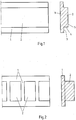
- Fig. 1 shows a sealing member for a lightweight board, with an outer portion 1 and an integral with the outer portion 1 inner portion 2. This is an extruded sealing element, of which only a part in Fig. 1 is shown. The length of the sealing element is adapted to the particular application.
- the sealing member is made of an elastic material having a good thermal resistance. It can be PVC.
- the sections 1, 2 together have a T-shaped cross-section.
- section 1 and / or section 2 have sealing surfaces 3,4,5 for bonding with at least one element of a lightweight board 6.
- Fig. 2 shows that the inner portion 2 can be made in sections in the longitudinal direction of the sealing element. Thereby, the elasticity of the sealing member can be improved.
- the dashed line in Fig. 2 shows that the entire width of the section 2 for the sectional spacing of the inner portions 2 is used. It is also possible to choose a smaller or larger width, so that the inner sections 2 can still be partially connected in one piece or even the outer sections are partially executed in sections.
- the inner sections 2 can also be separated from each other by cuts and thus executed in sections.
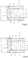
- a sealing element is shown inserted in a lightweight panel 6 state.
- the area 7 in Fig. 3 is a part of a section 16 of the lightweight panel 6, which is in Fig. 9 is explained. It may be a round, rectangular or otherwise shaped cutout 16.
- the outer portion 1 has a height H 1 , which corresponds to the distance of the facing away from the central position 9 surfaces of the cover plates 8 and that the inner portion 2 has a height H 2 , the distance of the central layer 9 facing surfaces the cover plates 8 corresponds.
- Fig. 3A there is the known lightweight panel 6 of two cover plates 8 and a central layer 9.
- the middle layer 9 is milled in the region of the inner portion 2 of the sealing element.
- the outer portion 1 abuts against the narrow surfaces 10 of the cover plates 8 and seals the region 7 of the cutout 16 of the lightweight panel 6 from the environment.
- Fig. 3B is an alternative embodiment to Fig. 3A shown.
- the height H 1 of the outer portion 1 may be selected so that a small lip 20 is formed by the outer portion 1, which engages over the top of the upper cover plate 8 and the narrow surface 10 of the upper cover plate 8 again improved, especially against moisture protects , Similarly, such a lip 20 may be provided for the lower cover plate 8.
- the sealing element has sealing surfaces 3.
- the sealing surfaces 3 of the sealing element are connected to the narrow sides 10 of the lightweight panel 6 by an adhesive 11. As a result, a higher tightness between the sealing element and the lightweight panel 6 is given.
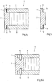
- Fig. 5 shows that it is alternatively possible to provide an adhesive tape 12 on the sealing surfaces 3.
- a cover 13 is provided which activates the adhesive tape 12 after removal.
- the inner portion 2 has a suitable width for attaching a mechanical fastener 14.
- the fastening element 14 may be, for example, a screw or a dowel, but also other mechanical fastening elements.
- the fasteners 14 connect the lightweight panel 6 with the sealing element.
- a fastener 14 may connect another member 18 to the seal member, with the inner portion 2 again having a suitable width therefor.
- the element 18 may be any element 18, such as an element 18 necessary to secure a hotplate or sink, not shown.
- the outer portion 1 have a step 19, which serves for engaging behind a mechanical fastener 14.
- the mechanical fastening element 14 may be, for example, a hook.
- the mechanical fastener 14 for example, designed as a hook or claw, press into the outer portion 1.
- a groove for receiving a mechanical fastening element 14 is provided be.
- the width of the outer portion 1 is chosen to be correspondingly large.
- Fig. 8 shows that in the region of the cutout 16, the cover plates 8 can also be partially milled out.
- all surfaces 3, 4 and 5 of the sealing element are designed as sealing surfaces 3, 4 and 5 with an adhesive 11 for connecting the sealing element to the lightweight building board 6.
- the height H 2 of the inner portion 2 is adapted to the cutout of the cover plates 8, but smaller than the height H 1 of the outer portion.
- Fig. 9 shows a lightweight panel 6 in a plan view.
- a sealing element is arranged, of which the outer portion 1 is visible.
- the invisible inner portion 2 is indicated by the dashed line.
- the two longitudinal ends of the sealing element are mutually sealingly against each other at the point 17 at.
- the invention is not limited to round cutouts, as in Fig. 9 shown limited. It may also be oval, rectangular or square cutouts, in particular with round corners act.
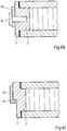
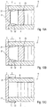
- FIGS. 10A to C different embodiments of a sealing element for a lightweight panel 6 are shown, in which the sealing element has been secured by means of a latch or clip connection to the cover plates 8 of the lightweight panel 6. It can be clearly seen that in the mounted state of the sealing element, as for example in the FIGS. 3A and B , the inner portion 2 protrudes from the outer portion 1 in the direction of the central position. In contrast to the FIGS. 3A and B is however with the FIGS. 10A to C the inner portion 2 is provided with two projections 21, so divided into two, wherein the two projections 21 protrude in the direction of the central position.
- Both projections 21 each have a latching lug 15 which cooperates with a corresponding recess 22 in the respective cover plate 8.
- the recesses 22 are provided on the inside of the cover plate 8 and the locking lugs 15 are away from one another.
- the depressions 22 are provided on the outside of the cover plate 8 and the latching lugs 15 face one another.
- a support bar 25 is provided, which in the present case extends parallel to the narrow surface of the lightweight building panel 6 to be covered.
- a decoration (not shown) is provided, which on the visible in the mounted state outwardly part of the outer portion 1 and, in the case of Fig. 10C , the inner portion 2 is applied, wherein the decor corresponds to that of the cover plates 8. In this way, a visually appealing and uniform appearance of the finished lightweight panel is achieved.
- FIGS. 10A and B A distinction between the embodiments of the FIGS. 10A and B is the cross-sectional shape of the inner portion 2.
- the inner portion 2 in addition to the two projections 21 still a the two projections 21 connecting portion, whereas according to Fig. 10B the two projections 21 are connected only to the outer portion 1 of the sealing element.
- Fig. 11 shows a further embodiment of a sealing element according to the present invention.
- the construction is comparable to that of the sealing elements of the Figures 10A and 10B , However, in the present case, each projection 21 is part of a corresponding spring profile 23, which cooperates with a corresponding groove profile 24 in the cover plate 8.
- the sealing element can have, for example, one or more lips for bearing against the element to be placed in the cutout of the lightweight component.
- the cross section of the sealing member is not limited to a T-shaped cross section.
- a connection of the sealing element may be provided with the center layer of the lightweight board.
Landscapes
- Engineering & Computer Science (AREA)
- Architecture (AREA)
- Life Sciences & Earth Sciences (AREA)
- Civil Engineering (AREA)
- Structural Engineering (AREA)
- Mechanical Engineering (AREA)
- Wood Science & Technology (AREA)
- Forests & Forestry (AREA)
- Finishing Walls (AREA)
- Building Environments (AREA)
- Panels For Use In Building Construction (AREA)
- Securing Of Glass Panes Or The Like (AREA)
Claims (14)
- Panneau alvéolaire (6), qui est formé de deux panneaux de couverture (8) et d'une couche médiane (9) disposées entre elles, avec au moins une surface étroite et avec un élément recouvrant la surface étroite,- avec une section extérieure (1), la section extérieure (1) comportant une hauteur (H1), qui correspond au moins à la distance entre les surfaces des panneaux de couverture (8) opposées à la couche médiane (9), et- avec une section intérieure (2), pour laquelle les côtés opposés l'un à l'autre de la section (2) comportent une distance (H2), qui correspond au moins à la distance entre les surfaces des panneaux de couverture (8) tournées vers la couche médiane (9),la section extérieure (1) étant formée en une seule pièce avec la section intérieure (2), l'élément étant un élément d'étanchéité avec au moins une surface d'étanchéité (3, 4, 5) pour étanchéifier au moins une surface étroite (10) d'un panneau de couverture (8) et/ou d'une couche médiane (9) du panneau alvéolaire (6), qui est constitué de telle manière que cela permet à l'état monté une étanchéification de la surface étroite (10) du panneau de couverture (8) et/ou de la couche médiane (9) du panneau alvéolaire (6),
caractérisé en ce
que les deux panneaux de couverture (8) sont formés d'un matériau dérivé du bois,
que la couche médiane (9) est formée d'une alvéole en carton,
que la surface d'étanchéité (3, 4, 5) est munie d'une masse d'étanchéité,
que la section intérieure (2) comporte des ergots d'insertion (15) à insérer sur les panneaux de couverture (8), et
que des cavités correspondant aux ergots d'insertion (15) sont prévues dans les panneaux de couverture (8). - Panneau alvéolaire (6), selon la revendication 1,
caractérisé en ce
qu'à l'état monté de l'élément, la section intérieure (2) ressort par rapport à la section extérieure (1) dans le sens de la couche médiane (9). - Panneau alvéolaire (6), selon la revendication 1 ou 2,
caractérisé en ce
que la section intérieure (2) comporte au moins une saillie (21), de préférence deux saillies (21), qui ressort/ressortent par rapport à la section extérieure (1) dans le sens de la couche médiane (9), notamment au moins une des saillies (21) comportant un ergot d'insertion (15), qui coopère avec une cavité correspondante (22) dans le panneau de couverture (8), les cavités (22) étant de préférence prévues sur le côté intérieur du panneau de couverture (8) et les ergots d'insertion (15) s'écartant l'un de l'autre. - Panneau alvéolaire (6), selon la revendication 3,
caractérisé en ce
que les cavités (22) sont prévues sur le côté extérieur du panneau de couverture (8) et les ergots d'insertion (15) se font face. - Panneau alvéolaire (6), selon la revendication 3 ou 4,
caractérisé en ce
qu'au moins une saillie (21) fait partie intégrante d'un profilé à languette (23), qui peut coopérer avec un profilé à rainure correspondant (24) dans le panneau de couverture (8) ou au moins une saillie (21) fait partie intégrante d'un profilé à rainure (24) qui peut coopérer avec un profilé à languette correspondant (23) dans le panneau de couverture (8). - Panneau alvéolaire (6), selon l'une quelconque des revendications précédentes,
caractérisé en ce
que la hauteur (H1) de la section extérieure (1) correspond à la distance (H2) des côtés opposés les uns aux autres de la section intérieure (2). - Panneau alvéolaire (6), selon l'une quelconque des revendications précédentes,
caractérisé en ce
que les sections (1, 2) sont extrudées et/ou fabriquées à partir d'un matériau élastique et/ou comportent une résistance thermique et/ou sont fabriquées à partir d'un chlorure de polyvinyle (CPV) ou de polyamide. - Panneau alvéolaire (6), selon l'une quelconque des revendications précédentes,
caractérisé en ce
que les sections (1, 2) présentent ensemble une section en forme de T. - Panneau alvéolaire (6), selon l'une quelconque des revendications précédentes,
caractérisé en ce
qu'au moins une surface d'étanchéité (3, 4, 5), est dotée de préférence en usine d'une matière adhésive (11) et/ou d'un ruban adhésif (12) et/ou d'une masse de scellement en tant que masse d'étanchéité. - Panneau alvéolaire (6), selon l'une quelconque des revendications précédentes,
caractérisé en ce
que la section intérieure (2) comporte une largeur appropriée pour la fixation d'un élément de fixation mécanique (14) et/ou est exécutée par tronçon dans le sens longitudinal de l'élément. - Panneau alvéolaire (6), selon l'une quelconque des revendications précédentes,
caractérisé en ce
que la section extérieure (1) comporte au moins une lèvre (20) pour venir recouvrir la surface d'un des panneaux de couverture (8). - Panneau alvéolaire (6), selon l'une quelconque des revendications précédentes,
caractérisé en ce
qu'à l'état monté de l'élément, la partie visible de la section extérieure (1) et/ou de la section intérieure (2) est dotée d'un décor et/ou d'une structure, le décor et/ou la structure a été fabriqué notamment par extrusion des sections (1, 2) et/ou le décor est formé par un revêtement et/ou le décor et/ou la structure est formé par une feuille de métal, qui est notamment polie, brossée et/ou gaufrée. - Panneau alvéolaire (6), selon l'une quelconque des revendications précédentes,
caractérisé en ce
qu'une traverse d'appui (25) est prévue proche et/ou à distance de l'élément, qui passe en particulier parallèlement à la surface étroite (10) à recouvrir. - Utilisation d'un élément pour recouvrir une surface étroite d'un panneau alvéolaire (6) avec une section extérieure (1), la section extérieure (1) comportant une hauteur (H1), qui correspond au moins à la distance entre les surfaces des panneaux de couverture (8) opposées à la couche médiane (9) et avec une section intérieure (2) pour laquelle les côtés de la section (2) opposés les uns aux autres comportent une distance (H2) qui correspond au moins à la distance entre les surfaces des panneaux de couverture (8) tournées vers la couche médiane (9), la section extérieure (1) étant constituée en une seule pièce avec la section intérieure (2), l'élément étant un élément d'étanchéité avec au moins une surface d'étanchéité (3, 4, 5) pour étanchéifier au moins une surface étroite (10) d'un panneau de couverture (8) et/ou d'une couche médiane (9) du panneau alvéolaire (6), qui est constitué de telle manière que cela permet à l'état monté une étanchéification de la surface étroite (10) du panneau de couverture (8) et/ou de la couche médiane (9) du panneau alvéolaire (6), les deux panneaux de couverture (8) étant formées à partir d'un matériau dérivé du bois, la couche médiane (9) étant formée à partir d'une alvéole de carton, la surface d'étanchéité (3, 4, 5) étant dotée d'une masse d'étanchéité, la section intérieure (2) comportant des ergots d'insertion (15) à insérer sur les panneaux de couverture (8), des cavités correspondant aux ergots d'insertion (15) étant prévues dans les panneaux de couverture (8), pour étanchéifier au moins une surface étroite d'un panneau alvéolaire (6) qui est formé de deux panneaux de couverture (8) en un matériau dérivé du bois et d'une couche médiane (9) disposée entre elles, constituée d'une alvéole de carton.
Priority Applications (1)
| Application Number | Priority Date | Filing Date | Title |
|---|---|---|---|
| PL07728856T PL2016237T3 (pl) | 2006-05-11 | 2007-05-07 | Element uszczelniający dla lekkiej płyty budowlanej |
Applications Claiming Priority (2)
| Application Number | Priority Date | Filing Date | Title |
|---|---|---|---|
| DE102006022314A DE102006022314A1 (de) | 2006-05-11 | 2006-05-11 | Abdichtungselement für eine Leichtbauplatte |
| PCT/EP2007/054403 WO2007131904A1 (fr) | 2006-05-11 | 2007-05-07 | Élément d'étanchéite pour un panneau de construction léger |
Publications (2)
| Publication Number | Publication Date |
|---|---|
| EP2016237A1 EP2016237A1 (fr) | 2009-01-21 |
| EP2016237B1 true EP2016237B1 (fr) | 2017-02-15 |
Family
ID=38328560
Family Applications (1)
| Application Number | Title | Priority Date | Filing Date |
|---|---|---|---|
| EP07728856.1A Not-in-force EP2016237B1 (fr) | 2006-05-11 | 2007-05-07 | Élément d'étanchéite pour un panneau de construction léger |
Country Status (8)
| Country | Link |
|---|---|
| EP (1) | EP2016237B1 (fr) |
| AU (1) | AU2007251632B2 (fr) |
| DE (1) | DE102006022314A1 (fr) |
| ES (1) | ES2624005T3 (fr) |
| LT (1) | LT2016237T (fr) |
| PL (1) | PL2016237T3 (fr) |
| PT (1) | PT2016237T (fr) |
| WO (1) | WO2007131904A1 (fr) |
Families Citing this family (8)
| Publication number | Priority date | Publication date | Assignee | Title |
|---|---|---|---|---|
| DE502007001395D1 (de) * | 2007-02-26 | 2009-10-08 | Homag Holzbearbeitungssysteme | Verfahren zum Anhaften von Kantenmaterial an Leichtbauplatten |
| DE202007017769U1 (de) * | 2007-12-20 | 2008-12-24 | Homag Holzbearbeitungssysteme Ag | Leichtbauplatte |
| DE202009001546U1 (de) * | 2009-02-10 | 2010-07-01 | Homag Holzbearbeitungssysteme Ag | Leichtbauplatte |
| EP2452792A1 (fr) | 2010-11-15 | 2012-05-16 | Luigi Frati S.p.A. | Panneau et procédé de fabrication de panneaux |
| DE102013208121A1 (de) * | 2013-05-03 | 2014-11-06 | Homag Holzbearbeitungssysteme Gmbh | Stützkantenverbund |
| US20160095438A1 (en) * | 2014-10-03 | 2016-04-07 | EZ Countertop, LLC | End-cap system and device for use with countertops |
| EP3031588B1 (fr) * | 2014-12-12 | 2021-09-15 | BIESSE S.p.A. | Procédé pour meuler des panneaux en bois à noyau creux |
| DE102015111579A1 (de) * | 2015-07-16 | 2017-01-19 | Hörmann Kg Brandis | Verfahren zum Herstellen eines Tür- oder Torelements unter Verwendung eines Metallsandwichs |
Citations (1)
| Publication number | Priority date | Publication date | Assignee | Title |
|---|---|---|---|---|
| DE29617862U1 (de) * | 1996-10-15 | 1997-01-16 | Knierim GmbH u. Co KG Metall- und Kunststoffverarbeitung, 34134 Kassel | Wand- und/oder Türelement sowie Rahmenteil und Deckplatte zu dessen Herstellung |
Family Cites Families (12)
| Publication number | Priority date | Publication date | Assignee | Title |
|---|---|---|---|---|
| BE361337A (fr) * | 1928-06-25 | |||
| FR949477A (fr) * | 1947-07-10 | 1949-08-31 | Panneau composite | |
| DE1843810U (de) * | 1961-07-06 | 1961-12-21 | Roemmler G M B H H | Verbundplatte. |
| DE2425014B2 (de) * | 1974-05-24 | 1976-08-26 | Vereinigte Flugtechnische Werke-Fokker GmbH, 2800 Bremen | Verfahren zum herstellen von leichtbauplatten |
| GB1493613A (en) * | 1974-11-06 | 1977-11-30 | Wynn Ltd G | Sectional members |
| LU81479A1 (fr) * | 1979-07-09 | 1979-10-31 | Para Press Sa | Procede de fabrication d'un vantail de porte de caravane et vantail obtenu par la mise en oeuvre de ce procede |
| US4971849A (en) * | 1989-08-14 | 1990-11-20 | Extrusions Division | Readily bendable extruded elastomeric trim strip |
| EP0584041A1 (fr) * | 1992-08-06 | 1994-02-23 | Ciba-Geigy Ag | Profile de recouvrement pour chant de panneau |
| DE19506158A1 (de) * | 1995-02-22 | 1996-08-29 | Oeco Team Unternehmens Und Umw | Halte- und Abschlußprofil |
| DE29510629U1 (de) * | 1995-06-30 | 1995-09-14 | Georg Hottes Granit- und Syenitwerk GmbH & Co. KG, 64401 Groß-Bieberau | Naturstein-Verbundplatte |
| CN1575966A (zh) * | 2003-07-28 | 2005-02-09 | 冷鹭浩 | 一种蜂窝纸内芯复合板 |
| DE102004007157B4 (de) * | 2004-02-12 | 2005-12-08 | Ima Klessmann Gmbh Holzbearbeitungssysteme | Verfahren zum Herstellen von Platten aus Holz und/oder Holzersatzstoffen und danach hergestellte Platte |
-
2006
- 2006-05-11 DE DE102006022314A patent/DE102006022314A1/de not_active Ceased
-
2007
- 2007-05-07 PL PL07728856T patent/PL2016237T3/pl unknown
- 2007-05-07 AU AU2007251632A patent/AU2007251632B2/en not_active Ceased
- 2007-05-07 WO PCT/EP2007/054403 patent/WO2007131904A1/fr not_active Ceased
- 2007-05-07 PT PT77288561T patent/PT2016237T/pt unknown
- 2007-05-07 ES ES07728856.1T patent/ES2624005T3/es active Active
- 2007-05-07 EP EP07728856.1A patent/EP2016237B1/fr not_active Not-in-force
- 2007-05-07 LT LTEP07728856.1T patent/LT2016237T/lt unknown
Patent Citations (1)
| Publication number | Priority date | Publication date | Assignee | Title |
|---|---|---|---|---|
| DE29617862U1 (de) * | 1996-10-15 | 1997-01-16 | Knierim GmbH u. Co KG Metall- und Kunststoffverarbeitung, 34134 Kassel | Wand- und/oder Türelement sowie Rahmenteil und Deckplatte zu dessen Herstellung |
Also Published As
| Publication number | Publication date |
|---|---|
| AU2007251632A1 (en) | 2007-11-22 |
| EP2016237A1 (fr) | 2009-01-21 |
| PL2016237T3 (pl) | 2017-07-31 |
| ES2624005T3 (es) | 2017-07-12 |
| LT2016237T (lt) | 2017-04-25 |
| WO2007131904A1 (fr) | 2007-11-22 |
| DE102006022314A1 (de) | 2007-11-22 |
| AU2007251632B2 (en) | 2010-11-11 |
| PT2016237T (pt) | 2017-05-03 |
Similar Documents
| Publication | Publication Date | Title |
|---|---|---|
| EP2016237B1 (fr) | Élément d'étanchéite pour un panneau de construction léger | |
| EP2834526B1 (fr) | Panneau de construction léger, système d'assemblage et procédé de fabrication d'un système d'assemblage | |
| DE69312927T2 (de) | Platte und verfahren zu ihrer herstellung | |
| EP2015652B1 (fr) | Élément supplementaire pour une partie de meuble constituée d'un panneau de construction léger, partie de meuble et meuble | |
| EP2051848B1 (fr) | Panneau structural léger | |
| AT10584U1 (de) | Stockrahmen und/oder flugelrahmen und verfahren zu seiner herstellung | |
| EP2027349B1 (fr) | Procede de fabrication de plaque de construction légère avec barre collé | |
| EP2379321B1 (fr) | Élément de construction, en particulier panneau sandwich | |
| DE4222971C2 (de) | Paneel zur Abdeckung bzw. Verkleidung | |
| EP2525010B1 (fr) | Panneau de construction léger, procédé de fabrication et dispositif de fabrication pour ce panneau | |
| EP2170599B1 (fr) | Panneau de construction léger | |
| EP2147778B1 (fr) | Plaque de construction légère pour la construction de meubles | |
| EP2105065A1 (fr) | Corps de meuble | |
| EP1867796B1 (fr) | Panneaux composites pour les travaux de finition intérieure | |
| EP1992759A2 (fr) | Panneau de construction léger | |
| DE102014101600B4 (de) | Profilierung und Stützeinheit für Möbel | |
| DE4337474A1 (de) | Türblattaufbau | |
| AT412412B (de) | Adapterprofil | |
| DE9316796U1 (de) | Türblattaufbau | |
| DE202014011293U1 (de) | Stützeinheit für Möbel | |
| DE202014011271U1 (de) | Profilierung für Möbel |
Legal Events
| Date | Code | Title | Description |
|---|---|---|---|
| PUAI | Public reference made under article 153(3) epc to a published international application that has entered the european phase |
Free format text: ORIGINAL CODE: 0009012 |
|
| 17P | Request for examination filed |
Effective date: 20081031 |
|
| AK | Designated contracting states |
Kind code of ref document: A1 Designated state(s): AT BE BG CH CY CZ DE DK EE ES FI FR GB GR HU IE IS IT LI LT LU LV MC MT NL PL PT RO SE SI SK TR |
|
| AX | Request for extension of the european patent |
Extension state: AL BA HR MK RS |
|
| 17Q | First examination report despatched |
Effective date: 20100927 |
|
| RAP1 | Party data changed (applicant data changed or rights of an application transferred) |
Owner name: FRITZ EGGER GMBH & CO. OG |
|
| DAX | Request for extension of the european patent (deleted) | ||
| RAP1 | Party data changed (applicant data changed or rights of an application transferred) |
Owner name: FRITZ EGGER GMBH & CO. OG |
|
| GRAP | Despatch of communication of intention to grant a patent |
Free format text: ORIGINAL CODE: EPIDOSNIGR1 |
|
| INTG | Intention to grant announced |
Effective date: 20161110 |
|
| GRAS | Grant fee paid |
Free format text: ORIGINAL CODE: EPIDOSNIGR3 |
|
| GRAA | (expected) grant |
Free format text: ORIGINAL CODE: 0009210 |
|
| AK | Designated contracting states |
Kind code of ref document: B1 Designated state(s): AT BE BG CH CY CZ DE DK EE ES FI FR GB GR HU IE IS IT LI LT LU LV MC MT NL PL PT RO SE SI SK TR |
|
| REG | Reference to a national code |
Ref country code: CH Ref legal event code: EP Ref country code: GB Ref legal event code: FG4D Free format text: NOT ENGLISH |
|
| REG | Reference to a national code |
Ref country code: IE Ref legal event code: FG4D Free format text: LANGUAGE OF EP DOCUMENT: GERMAN |
|
| REG | Reference to a national code |
Ref country code: AT Ref legal event code: REF Ref document number: 867993 Country of ref document: AT Kind code of ref document: T Effective date: 20170315 |
|
| REG | Reference to a national code |
Ref country code: DE Ref legal event code: R096 Ref document number: 502007015443 Country of ref document: DE |
|
| REG | Reference to a national code |
Ref country code: CH Ref legal event code: NV Representative=s name: SCHMAUDER AND PARTNER AG PATENT- UND MARKENANW, CH |
|
| REG | Reference to a national code |
Ref country code: NL Ref legal event code: FP |
|
| REG | Reference to a national code |
Ref country code: PT Ref legal event code: SC4A Ref document number: 2016237 Country of ref document: PT Date of ref document: 20170503 Kind code of ref document: T Free format text: AVAILABILITY OF NATIONAL TRANSLATION Effective date: 20170424 |
|
| REG | Reference to a national code |
Ref country code: SE Ref legal event code: TRGR |
|
| REG | Reference to a national code |
Ref country code: FR Ref legal event code: PLFP Year of fee payment: 11 |
|
| REG | Reference to a national code |
Ref country code: ES Ref legal event code: FG2A Ref document number: 2624005 Country of ref document: ES Kind code of ref document: T3 Effective date: 20170712 |
|
| PG25 | Lapsed in a contracting state [announced via postgrant information from national office to epo] |
Ref country code: GR Free format text: LAPSE BECAUSE OF FAILURE TO SUBMIT A TRANSLATION OF THE DESCRIPTION OR TO PAY THE FEE WITHIN THE PRESCRIBED TIME-LIMIT Effective date: 20170516 Ref country code: FI Free format text: LAPSE BECAUSE OF FAILURE TO SUBMIT A TRANSLATION OF THE DESCRIPTION OR TO PAY THE FEE WITHIN THE PRESCRIBED TIME-LIMIT Effective date: 20170215 |
|
| PG25 | Lapsed in a contracting state [announced via postgrant information from national office to epo] |
Ref country code: LV Free format text: LAPSE BECAUSE OF FAILURE TO SUBMIT A TRANSLATION OF THE DESCRIPTION OR TO PAY THE FEE WITHIN THE PRESCRIBED TIME-LIMIT Effective date: 20170215 Ref country code: LU Free format text: LAPSE BECAUSE OF NON-PAYMENT OF DUE FEES Effective date: 20170531 Ref country code: BG Free format text: LAPSE BECAUSE OF FAILURE TO SUBMIT A TRANSLATION OF THE DESCRIPTION OR TO PAY THE FEE WITHIN THE PRESCRIBED TIME-LIMIT Effective date: 20170515 |
|
| PG25 | Lapsed in a contracting state [announced via postgrant information from national office to epo] |
Ref country code: SK Free format text: LAPSE BECAUSE OF FAILURE TO SUBMIT A TRANSLATION OF THE DESCRIPTION OR TO PAY THE FEE WITHIN THE PRESCRIBED TIME-LIMIT Effective date: 20170215 Ref country code: EE Free format text: LAPSE BECAUSE OF FAILURE TO SUBMIT A TRANSLATION OF THE DESCRIPTION OR TO PAY THE FEE WITHIN THE PRESCRIBED TIME-LIMIT Effective date: 20170215 Ref country code: RO Free format text: LAPSE BECAUSE OF FAILURE TO SUBMIT A TRANSLATION OF THE DESCRIPTION OR TO PAY THE FEE WITHIN THE PRESCRIBED TIME-LIMIT Effective date: 20170215 Ref country code: CZ Free format text: LAPSE BECAUSE OF FAILURE TO SUBMIT A TRANSLATION OF THE DESCRIPTION OR TO PAY THE FEE WITHIN THE PRESCRIBED TIME-LIMIT Effective date: 20170215 |
|
| REG | Reference to a national code |
Ref country code: DE Ref legal event code: R097 Ref document number: 502007015443 Country of ref document: DE |
|
| PG25 | Lapsed in a contracting state [announced via postgrant information from national office to epo] |
Ref country code: DK Free format text: LAPSE BECAUSE OF FAILURE TO SUBMIT A TRANSLATION OF THE DESCRIPTION OR TO PAY THE FEE WITHIN THE PRESCRIBED TIME-LIMIT Effective date: 20170215 |
|
| PLBE | No opposition filed within time limit |
Free format text: ORIGINAL CODE: 0009261 |
|
| STAA | Information on the status of an ep patent application or granted ep patent |
Free format text: STATUS: NO OPPOSITION FILED WITHIN TIME LIMIT |
|
| 26N | No opposition filed |
Effective date: 20171116 |
|
| PG25 | Lapsed in a contracting state [announced via postgrant information from national office to epo] |
Ref country code: MC Free format text: LAPSE BECAUSE OF FAILURE TO SUBMIT A TRANSLATION OF THE DESCRIPTION OR TO PAY THE FEE WITHIN THE PRESCRIBED TIME-LIMIT Effective date: 20170215 |
|
| REG | Reference to a national code |
Ref country code: IE Ref legal event code: MM4A |
|
| PG25 | Lapsed in a contracting state [announced via postgrant information from national office to epo] |
Ref country code: SI Free format text: LAPSE BECAUSE OF FAILURE TO SUBMIT A TRANSLATION OF THE DESCRIPTION OR TO PAY THE FEE WITHIN THE PRESCRIBED TIME-LIMIT Effective date: 20170215 |
|
| PG25 | Lapsed in a contracting state [announced via postgrant information from national office to epo] |
Ref country code: LU Free format text: LAPSE BECAUSE OF NON-PAYMENT OF DUE FEES Effective date: 20170507 |
|
| PG25 | Lapsed in a contracting state [announced via postgrant information from national office to epo] |
Ref country code: IE Free format text: LAPSE BECAUSE OF NON-PAYMENT OF DUE FEES Effective date: 20170507 |
|
| REG | Reference to a national code |
Ref country code: FR Ref legal event code: PLFP Year of fee payment: 12 |
|
| PG25 | Lapsed in a contracting state [announced via postgrant information from national office to epo] |
Ref country code: MT Free format text: LAPSE BECAUSE OF FAILURE TO SUBMIT A TRANSLATION OF THE DESCRIPTION OR TO PAY THE FEE WITHIN THE PRESCRIBED TIME-LIMIT Effective date: 20170215 |
|
| PG25 | Lapsed in a contracting state [announced via postgrant information from national office to epo] |
Ref country code: HU Free format text: LAPSE BECAUSE OF FAILURE TO SUBMIT A TRANSLATION OF THE DESCRIPTION OR TO PAY THE FEE WITHIN THE PRESCRIBED TIME-LIMIT; INVALID AB INITIO Effective date: 20070507 |
|
| PG25 | Lapsed in a contracting state [announced via postgrant information from national office to epo] |
Ref country code: CY Free format text: LAPSE BECAUSE OF NON-PAYMENT OF DUE FEES Effective date: 20170215 |
|
| PG25 | Lapsed in a contracting state [announced via postgrant information from national office to epo] |
Ref country code: TR Free format text: LAPSE BECAUSE OF FAILURE TO SUBMIT A TRANSLATION OF THE DESCRIPTION OR TO PAY THE FEE WITHIN THE PRESCRIBED TIME-LIMIT Effective date: 20170215 |
|
| PG25 | Lapsed in a contracting state [announced via postgrant information from national office to epo] |
Ref country code: IS Free format text: LAPSE BECAUSE OF FAILURE TO SUBMIT A TRANSLATION OF THE DESCRIPTION OR TO PAY THE FEE WITHIN THE PRESCRIBED TIME-LIMIT Effective date: 20170615 |
|
| PGFP | Annual fee paid to national office [announced via postgrant information from national office to epo] |
Ref country code: FR Payment date: 20210518 Year of fee payment: 15 Ref country code: PT Payment date: 20210419 Year of fee payment: 15 Ref country code: DE Payment date: 20210517 Year of fee payment: 15 Ref country code: NL Payment date: 20210519 Year of fee payment: 15 Ref country code: IT Payment date: 20210518 Year of fee payment: 15 |
|
| PGFP | Annual fee paid to national office [announced via postgrant information from national office to epo] |
Ref country code: ES Payment date: 20210615 Year of fee payment: 15 Ref country code: CH Payment date: 20210517 Year of fee payment: 15 Ref country code: GB Payment date: 20210518 Year of fee payment: 15 Ref country code: SE Payment date: 20210517 Year of fee payment: 15 Ref country code: BE Payment date: 20210519 Year of fee payment: 15 Ref country code: AT Payment date: 20210519 Year of fee payment: 15 |
|
| PGFP | Annual fee paid to national office [announced via postgrant information from national office to epo] |
Ref country code: LT Payment date: 20220328 Year of fee payment: 16 |
|
| PGFP | Annual fee paid to national office [announced via postgrant information from national office to epo] |
Ref country code: PL Payment date: 20220502 Year of fee payment: 16 |
|
| REG | Reference to a national code |
Ref country code: DE Ref legal event code: R119 Ref document number: 502007015443 Country of ref document: DE |
|
| REG | Reference to a national code |
Ref country code: CH Ref legal event code: PL |
|
| REG | Reference to a national code |
Ref country code: SE Ref legal event code: EUG |
|
| REG | Reference to a national code |
Ref country code: NL Ref legal event code: MM Effective date: 20220601 |
|
| REG | Reference to a national code |
Ref country code: AT Ref legal event code: MM01 Ref document number: 867993 Country of ref document: AT Kind code of ref document: T Effective date: 20220507 |
|
| REG | Reference to a national code |
Ref country code: BE Ref legal event code: MM Effective date: 20220531 |
|
| GBPC | Gb: european patent ceased through non-payment of renewal fee |
Effective date: 20220507 |
|
| PG25 | Lapsed in a contracting state [announced via postgrant information from national office to epo] |
Ref country code: SE Free format text: LAPSE BECAUSE OF NON-PAYMENT OF DUE FEES Effective date: 20220508 Ref country code: PT Free format text: LAPSE BECAUSE OF NON-PAYMENT OF DUE FEES Effective date: 20221107 Ref country code: LI Free format text: LAPSE BECAUSE OF NON-PAYMENT OF DUE FEES Effective date: 20220531 Ref country code: CH Free format text: LAPSE BECAUSE OF NON-PAYMENT OF DUE FEES Effective date: 20220531 Ref country code: AT Free format text: LAPSE BECAUSE OF NON-PAYMENT OF DUE FEES Effective date: 20220507 |
|
| PG25 | Lapsed in a contracting state [announced via postgrant information from national office to epo] |
Ref country code: FR Free format text: LAPSE BECAUSE OF NON-PAYMENT OF DUE FEES Effective date: 20220531 |
|
| PG25 | Lapsed in a contracting state [announced via postgrant information from national office to epo] |
Ref country code: GB Free format text: LAPSE BECAUSE OF NON-PAYMENT OF DUE FEES Effective date: 20220507 Ref country code: DE Free format text: LAPSE BECAUSE OF NON-PAYMENT OF DUE FEES Effective date: 20221201 Ref country code: BE Free format text: LAPSE BECAUSE OF NON-PAYMENT OF DUE FEES Effective date: 20220531 |
|
| REG | Reference to a national code |
Ref country code: ES Ref legal event code: FD2A Effective date: 20230627 |
|
| PG25 | Lapsed in a contracting state [announced via postgrant information from national office to epo] |
Ref country code: NL Free format text: LAPSE BECAUSE OF NON-PAYMENT OF DUE FEES Effective date: 20220601 |
|
| PG25 | Lapsed in a contracting state [announced via postgrant information from national office to epo] |
Ref country code: IT Free format text: LAPSE BECAUSE OF NON-PAYMENT OF DUE FEES Effective date: 20220507 Ref country code: ES Free format text: LAPSE BECAUSE OF NON-PAYMENT OF DUE FEES Effective date: 20220508 |
|
| REG | Reference to a national code |
Ref country code: LT Ref legal event code: MM4D Effective date: 20230507 |
|
| PG25 | Lapsed in a contracting state [announced via postgrant information from national office to epo] |
Ref country code: LT Free format text: LAPSE BECAUSE OF NON-PAYMENT OF DUE FEES Effective date: 20230507 |
|
| PG25 | Lapsed in a contracting state [announced via postgrant information from national office to epo] |
Ref country code: PL Free format text: LAPSE BECAUSE OF NON-PAYMENT OF DUE FEES Effective date: 20230507 |
|
| PG25 | Lapsed in a contracting state [announced via postgrant information from national office to epo] |
Ref country code: PL Free format text: LAPSE BECAUSE OF NON-PAYMENT OF DUE FEES Effective date: 20230507 |