EP2016237B1 - Sealing element for a lightweight structural panel - Google Patents
Sealing element for a lightweight structural panel Download PDFInfo
- Publication number
- EP2016237B1 EP2016237B1 EP07728856.1A EP07728856A EP2016237B1 EP 2016237 B1 EP2016237 B1 EP 2016237B1 EP 07728856 A EP07728856 A EP 07728856A EP 2016237 B1 EP2016237 B1 EP 2016237B1
- Authority
- EP
- European Patent Office
- Prior art keywords
- lightweight board
- sealing
- middle layer
- cover plates
- section
- Prior art date
- Legal status (The legal status is an assumption and is not a legal conclusion. Google has not performed a legal analysis and makes no representation as to the accuracy of the status listed.)
- Not-in-force
Links
- 238000007789 sealing Methods 0.000 title claims description 117
- 239000000463 material Substances 0.000 claims description 15
- 239000000565 sealant Substances 0.000 claims description 11
- 239000002023 wood Substances 0.000 claims description 11
- 239000011111 cardboard Substances 0.000 claims description 9
- 239000002390 adhesive tape Substances 0.000 claims description 8
- 150000001875 compounds Chemical class 0.000 claims description 4
- 239000013013 elastic material Substances 0.000 claims description 4
- 239000002184 metal Substances 0.000 claims description 4
- 229910052751 metal Inorganic materials 0.000 claims description 4
- 239000004952 Polyamide Substances 0.000 claims description 2
- 239000011248 coating agent Substances 0.000 claims description 2
- 238000000576 coating method Methods 0.000 claims description 2
- 239000011888 foil Substances 0.000 claims description 2
- 229920002647 polyamide Polymers 0.000 claims description 2
- 238000001125 extrusion Methods 0.000 claims 1
- 239000003292 glue Substances 0.000 claims 1
- 230000001070 adhesive effect Effects 0.000 description 15
- 239000000853 adhesive Substances 0.000 description 12
- 238000004026 adhesive bonding Methods 0.000 description 3
- 238000010276 construction Methods 0.000 description 3
- 239000011094 fiberboard Substances 0.000 description 3
- 230000008901 benefit Effects 0.000 description 2
- 239000011093 chipboard Substances 0.000 description 2
- 238000005520 cutting process Methods 0.000 description 2
- 238000005034 decoration Methods 0.000 description 2
- 238000003780 insertion Methods 0.000 description 2
- 230000037431 insertion Effects 0.000 description 2
- 238000009434 installation Methods 0.000 description 2
- 238000004519 manufacturing process Methods 0.000 description 2
- 238000000034 method Methods 0.000 description 2
- 238000003801 milling Methods 0.000 description 2
- 210000001331 nose Anatomy 0.000 description 2
- 241000894006 Bacteria Species 0.000 description 1
- 239000004640 Melamine resin Substances 0.000 description 1
- 229920000877 Melamine resin Polymers 0.000 description 1
- 240000007182 Ochroma pyramidale Species 0.000 description 1
- 230000003213 activating effect Effects 0.000 description 1
- 230000004913 activation Effects 0.000 description 1
- 230000002411 adverse Effects 0.000 description 1
- 229910052782 aluminium Inorganic materials 0.000 description 1
- XAGFODPZIPBFFR-UHFFFAOYSA-N aluminium Chemical compound [Al] XAGFODPZIPBFFR-UHFFFAOYSA-N 0.000 description 1
- 210000000078 claw Anatomy 0.000 description 1
- 239000002131 composite material Substances 0.000 description 1
- 239000000356 contaminant Substances 0.000 description 1
- 238000009826 distribution Methods 0.000 description 1
- 230000000694 effects Effects 0.000 description 1
- 239000006260 foam Substances 0.000 description 1
- 238000010438 heat treatment Methods 0.000 description 1
- 244000144980 herd Species 0.000 description 1
- 229910052500 inorganic mineral Inorganic materials 0.000 description 1
- 238000009413 insulation Methods 0.000 description 1
- 239000011707 mineral Substances 0.000 description 1
- 239000003973 paint Substances 0.000 description 1
- 238000010422 painting Methods 0.000 description 1
- 239000011087 paperboard Substances 0.000 description 1
- 230000000149 penetrating effect Effects 0.000 description 1
- 239000004033 plastic Substances 0.000 description 1
- 239000004800 polyvinyl chloride Substances 0.000 description 1
- 238000003825 pressing Methods 0.000 description 1
- 230000001681 protective effect Effects 0.000 description 1
- 239000007787 solid Substances 0.000 description 1
- 241000894007 species Species 0.000 description 1
- 230000008961 swelling Effects 0.000 description 1
- 239000012815 thermoplastic material Substances 0.000 description 1
- 210000002268 wool Anatomy 0.000 description 1
Images


Classifications
-
- E—FIXED CONSTRUCTIONS
- E04—BUILDING
- E04C—STRUCTURAL ELEMENTS; BUILDING MATERIALS
- E04C2/00—Building elements of relatively thin form for the construction of parts of buildings, e.g. sheet materials, slabs, or panels
- E04C2/30—Building elements of relatively thin form for the construction of parts of buildings, e.g. sheet materials, slabs, or panels characterised by the shape or structure
- E04C2/34—Building elements of relatively thin form for the construction of parts of buildings, e.g. sheet materials, slabs, or panels characterised by the shape or structure composed of two or more spaced sheet-like parts
- E04C2/36—Building elements of relatively thin form for the construction of parts of buildings, e.g. sheet materials, slabs, or panels characterised by the shape or structure composed of two or more spaced sheet-like parts spaced apart by transversely-placed strip material, e.g. honeycomb panels
- E04C2/365—Building elements of relatively thin form for the construction of parts of buildings, e.g. sheet materials, slabs, or panels characterised by the shape or structure composed of two or more spaced sheet-like parts spaced apart by transversely-placed strip material, e.g. honeycomb panels by honeycomb structures
-
- B—PERFORMING OPERATIONS; TRANSPORTING
- B27—WORKING OR PRESERVING WOOD OR SIMILAR MATERIAL; NAILING OR STAPLING MACHINES IN GENERAL
- B27D—WORKING VENEER OR PLYWOOD
- B27D5/00—Other working of veneer or plywood specially adapted to veneer or plywood
- B27D5/003—Other working of veneer or plywood specially adapted to veneer or plywood securing a veneer strip to a panel edge
Definitions
- the invention relates to a lightweight board according to the preamble of claim 1.
- a lightweight board is known for example from the DE 195 06 158 A1 , Furthermore, the invention relates to a use of an element for covering a narrow surface of a lightweight building panel according to claim 14.
- Lightweight panels are well known in the art. Also in furniture and interior design, these are used for a long time in a variety of ways. The main field of application was and is the door construction here. So it is especially in room doors, which are therefore subject to low requirements in terms of heat and sound insulation, usually a frame member with a honeycomb core on both sides to plank and this then continue to process the corresponding holes, millings, etc. to a door element.
- the manufacturer of furniture does not need to manufacture lightweight panels today, as was the case earlier.
- a frame had to be made, possibly with several crossbars, on which the top layers were then applied and which had to accommodate the various fittings.
- cover layers lightweight fiber boards, mineral insulating wool, cardboard honeycomb or the like were introduced. This gave the item more compactness and possibly improved stability.
- the outer layers also had to be elaborately surface-treated in separate operations. For example, veneered or otherwise coated hardboards were used as cover layers, and the finished element can only be given its final surface by final painting.
- cover plates Today, lightweight panels are increasingly being manufactured industrially.
- a light middle layer is provided with cover plates, usually by gluing, so that a large-format, frameless composite arises.
- cover plates mostly from a wood material such as chipboard or fiberboard used.
- the plates used may already be coated, that is to say be provided with a laminate, a paint, a pressure with a seal, a melamine resin layer, a veneer, etc.
- cardboard honeycomb or foam boards are preferred.
- Honeycomb materials made of materials other than paper or cardboard may also be useful for certain purposes. For example, the thinnest sheet materials or even thin-walled metal such as aluminum can be used.
- middle layer of lightweight wood materials such as appropriate chipboard or fiberboard or solid wood of low density, such as balsa wood
- wood species are used for that, although not particularly low weight, but are well available and can be easily edited with cutting tools.
- the plates thus produced are then divided into the desired size. Depending on the intended use of the resulting elements, these are then provided with edges or an at least partially encircling frame is subsequently introduced. This is done by milling the edge area and subsequent gluing a frame profile, which in turn consists mostly of a wood material.
- Cutouts are necessary, for example, when using a lightweight board as a kitchen worktop to accommodate a sink or a stove top.
- the invention is therefore based on the technical problem of providing measures that allow protection of narrow surfaces and middle layers in a simple and individual way.
- the DE 296 17 862 U1 relates to a frame for producing a wall and / or door element, which may be provided on both sides with a cover plate made of metal, plastic or laminate.
- the frame extends exclusively between the cover plates and can thus be regarded as covering the narrow surface in the region between the cover plates.
- a lightweight board which is formed of two cover plates and a middle layer arranged therebetween, with at least one narrow surface and with a narrow surface covering element, with an outer Section, wherein the outer portion has a height which corresponds at least to the distance of the side facing away from the central position surfaces of the cover plates, and having an inner portion, wherein the opposite sides of the portion have a distance which at least the distance of the central position facing Surface of the cover plates corresponds, wherein the outer portion is formed integrally with the inner portion, wherein the element is a sealing member having at least one sealing surface for sealing at least a narrow surface of a cover plate and / or a middle layer of the lightweight board, the derar t is formed, that in the assembled state, a sealing of the narrow surface of the cover plate and / or the middle layer of the lightweight board allows, wherein the two cover plates are formed of a wood material, wherein the central layer
- the invention has thus recognized that such a lightweight board with a sealing element in a particularly simple way individually protection, in particular a seal that allows exposed by the neckline narrow surfaces.
- the sealing element can be inserted with its inner portion between the cover plates, wherein previously in the Einsteck Scheme the central layer is recessed, so that the outer portion with the narrow surfaces of the cover plates in contact and this, in particular by the outer portion performs a sealing function protects , Especially when using a lightweight board as a kitchen countertop arise manifold situations in which contaminants with the narrow surfaces and / or the middle layer can come into contact, which can lead to swelling of the polluted areas and / or herd of bacteria. Even when using a lightweight board in other applications, the narrow surfaces and / or the middle layer, in particular by moisture, deform adversely, discolor or develop undesirable properties in any other way.
- the inner section projects in the direction of the central position relative to the outer section. In this way, the inner portion can be inserted during assembly between the cover plates, which increases the sealing effect and stability.
- the inner section has at least one projection, preferably two projections, which projects in the direction of the central position relative to the outer section.
- at least one of the projections have a latching nose, which cooperates with a corresponding recess in the cover plate.
- the depressions on the inside of the Cover plate provided and the locking lugs are away from each other. This forms a clip connection which allows for easy assembly and disassembly of the sealing element.
- the depressions are provided on the outer side of the cover plate and the latching noses face each other.
- the height of the outer portion corresponds to the distance of the opposite sides of the inner portion.
- the at least one projection is part of a spring profile which can cooperate with a corresponding groove profile in the cover plate. It is also conceivable that the at least one projection is part of a groove profile, which can cooperate with a corresponding spring profile in the cover plate.
- a groove / spring connection also provides a simple way to assemble and disassemble the sealing element.
- the sections can be made of an elastic material, an outer portion is given, which is particularly good for round cutouts or cutouts with rounded edges on the narrow surfaces applies and thus seals very well.
- the inner portion can thereby be used non-positively in the recess of the middle layer and between the cover plates.
- the elasticity can be chosen such that a deformation of the inner portion does not lead to a pressing apart of the cover plates.
- the sections may also have thermal resistance. This is advantageous if the sealing element comes into contact with heating elements which are to be arranged in the cutout of the lightweight building board. Such an element can be stovetops.
- the thermal resistance may be provided up to a temperature of 150 ° C., in particular up to 100 ° C., so that the sealing element does not disadvantageously deform up to this temperature.
- all elastic materials can be used. It may be a thermoplastic material or PVC or polyamide.
- a particularly preferred embodiment is characterized in that the sections together have a T-shaped cross-section.
- a sealing element designed in this way allows a simple insertion into the recess of the middle layer and sealing of the narrow surfaces.
- At least one section at least one sealing surface for sealing at least one element of the lightweight building board, in particular a narrow surface of a Cover plate, a cover plate and / or middle layer
- the tightness and protection of the narrow surfaces and / or center layer can be further improved.
- for sealing what can be done by gluing the sealing surfaces with the narrow surfaces and / or the cover plates in the region of the central position and the middle layer itself, find any known adhesive use.
- a sealant has the advantage that it does not develop any appreciable adhesive effect after setting.
- the sealing element according to the invention can be removed at any time without own damage and without damaging the lightweight board. After removing any remains of the sealing compound from the sealing element or from the lightweight board, which is relatively easy due to the non-existing adhesive effect, both the sealing element can be used again and the lightweight panel are sealed at the previously sealed site again with a sealing element.
- the at least one sealing surface may be provided with an adhesive.
- the at least one sealing surface may be provided with an adhesive tape. The adhesive effect, in addition to a good seal and an optimal attachment of the sealing element is achieved.
- the adhesive, the adhesive tape and / or the sealing compound is already applied on the sealing element at the factory. Then, no separate sealant, meaning adhesive, tape or sealant, must be used, resulting in the handling of the product Sealing element facilitates.
- the sealant is preferably applied in a form which requires activation prior to assembly of the seal member.
- the adhesive, the adhesive tape and / or the sealant may be in encapsulated form.
- a cover for example a protective strip covering the adhesive tape, which merely has to be removed before bonding and thus activates the adhesive. This prevents the sealant comes into contact with other elements before activating, for example, the removal of the cover.
- the inner portion may have a width suitable for attaching a mechanical fastener.
- the sealing element can be arranged in the cutout and connected by a mechanical fastener to the lightweight board.
- the fastening element can be a screw or a dowel, which can ideally be removed again, so that the sealing element can be removed from the cutout if necessary.
- a mechanical fastening element can connect a further element to the sealing element.
- a stove top or a sink may be connected to the sealing element by a mechanical fastening element, for example a screw fastened in the sealing element.
- the outer portion may also have a step which is engaged behind by a mechanical fastener can.
- the mechanical fastener may then be a hook disposed on a stovetop or sink.
- the inner portion is designed in sections in the longitudinal direction of the sealing element. As a result, the elasticity of the sealing element, regardless of its material, be significantly improved.
- the recesses may have a width which is smaller than the width of the inner portions, so that the inner portions are still partially connected to each other.
- the recesses can also completely space the inner sections. It is even possible, if necessary, to choose the width of the recesses so that the recess is partially provided in the outer portion.
- a previously integral inner section can be performed in sections by sections.
- the cuts, as well as the aforementioned recesses may partially or completely separate the inner portions and may also be partially made into the outer portion.
- the outer section has at least one lip for reaching over the surface of one of the cover plates, so that a further increased protection against penetrating moisture is provided.
- the part of the outer section and / or of the inner section which is visible in the assembled state of the sealing element is provided with a decoration and / or a structure.
- the decor and / or structure can be made by extruding the sections.
- the decor is formed by a coating and / or by a metal foil which is in particular polished, brushed and / or embossed.
- the technical problem is solved independently by a use according to claim 14, that is by the use of an element for covering a narrow surface of a lightweight panel having an outer portion, wherein the outer portion has a height which is at least the distance away from the central position Surface of the cover plates corresponds, and with an inner portion, wherein the opposite sides of the portion have a distance which corresponds to at least the distance of the central layer facing surfaces of the cover plates, wherein the outer portion is integrally formed with the inner portion, wherein the Element is a sealing element having at least one sealing surface for sealing at least one narrow surface of a cover plate and / or a middle layer of the lightweight board, which is designed such that it seals the narrow surface of the cover plate un in the mounted state D / or the middle position of the lightweight board allows, wherein the two cover plates are formed of a wood material, wherein the central layer is formed of a cardboard honeycomb, wherein the sealing surface is provided with a sealing compound, wherein the inner portion locking lugs for latching to the cover plates, wherein the de
- FIGS. 1 to 6C and 8 and 9 described are not the subject of the present invention, but are merely for ease of understanding.
- the claimed invention is based on the FIGS. 7 . 10A to C and 11 described.
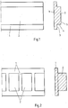
- Fig. 1 shows a sealing member for a lightweight board, with an outer portion 1 and an integral with the outer portion 1 inner portion 2. This is an extruded sealing element, of which only a part in Fig. 1 is shown. The length of the sealing element is adapted to the particular application.
- the sealing member is made of an elastic material having a good thermal resistance. It can be PVC.
- the sections 1, 2 together have a T-shaped cross-section.
- section 1 and / or section 2 have sealing surfaces 3,4,5 for bonding with at least one element of a lightweight board 6.
- Fig. 2 shows that the inner portion 2 can be made in sections in the longitudinal direction of the sealing element. Thereby, the elasticity of the sealing member can be improved.
- the dashed line in Fig. 2 shows that the entire width of the section 2 for the sectional spacing of the inner portions 2 is used. It is also possible to choose a smaller or larger width, so that the inner sections 2 can still be partially connected in one piece or even the outer sections are partially executed in sections.
- the inner sections 2 can also be separated from each other by cuts and thus executed in sections.
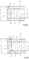
- a sealing element is shown inserted in a lightweight panel 6 state.
- the area 7 in Fig. 3 is a part of a section 16 of the lightweight panel 6, which is in Fig. 9 is explained. It may be a round, rectangular or otherwise shaped cutout 16.
- the outer portion 1 has a height H 1 , which corresponds to the distance of the facing away from the central position 9 surfaces of the cover plates 8 and that the inner portion 2 has a height H 2 , the distance of the central layer 9 facing surfaces the cover plates 8 corresponds.
- Fig. 3A there is the known lightweight panel 6 of two cover plates 8 and a central layer 9.
- the middle layer 9 is milled in the region of the inner portion 2 of the sealing element.
- the outer portion 1 abuts against the narrow surfaces 10 of the cover plates 8 and seals the region 7 of the cutout 16 of the lightweight panel 6 from the environment.
- Fig. 3B is an alternative embodiment to Fig. 3A shown.
- the height H 1 of the outer portion 1 may be selected so that a small lip 20 is formed by the outer portion 1, which engages over the top of the upper cover plate 8 and the narrow surface 10 of the upper cover plate 8 again improved, especially against moisture protects , Similarly, such a lip 20 may be provided for the lower cover plate 8.
- the sealing element has sealing surfaces 3.
- the sealing surfaces 3 of the sealing element are connected to the narrow sides 10 of the lightweight panel 6 by an adhesive 11. As a result, a higher tightness between the sealing element and the lightweight panel 6 is given.
- Fig. 5 shows that it is alternatively possible to provide an adhesive tape 12 on the sealing surfaces 3.
- a cover 13 is provided which activates the adhesive tape 12 after removal.
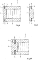
- the inner portion 2 has a suitable width for attaching a mechanical fastener 14.
- the fastening element 14 may be, for example, a screw or a dowel, but also other mechanical fastening elements.
- the fasteners 14 connect the lightweight panel 6 with the sealing element.
- a fastener 14 may connect another member 18 to the seal member, with the inner portion 2 again having a suitable width therefor.
- the element 18 may be any element 18, such as an element 18 necessary to secure a hotplate or sink, not shown.
- the outer portion 1 have a step 19, which serves for engaging behind a mechanical fastener 14.
- the mechanical fastening element 14 may be, for example, a hook.
- the mechanical fastener 14 for example, designed as a hook or claw, press into the outer portion 1.
- a groove for receiving a mechanical fastening element 14 is provided be.
- the width of the outer portion 1 is chosen to be correspondingly large.
- Fig. 8 shows that in the region of the cutout 16, the cover plates 8 can also be partially milled out.
- all surfaces 3, 4 and 5 of the sealing element are designed as sealing surfaces 3, 4 and 5 with an adhesive 11 for connecting the sealing element to the lightweight building board 6.
- the height H 2 of the inner portion 2 is adapted to the cutout of the cover plates 8, but smaller than the height H 1 of the outer portion.
- Fig. 9 shows a lightweight panel 6 in a plan view.
- a sealing element is arranged, of which the outer portion 1 is visible.
- the invisible inner portion 2 is indicated by the dashed line.
- the two longitudinal ends of the sealing element are mutually sealingly against each other at the point 17 at.
- the invention is not limited to round cutouts, as in Fig. 9 shown limited. It may also be oval, rectangular or square cutouts, in particular with round corners act.
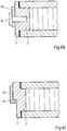
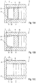
- FIGS. 10A to C different embodiments of a sealing element for a lightweight panel 6 are shown, in which the sealing element has been secured by means of a latch or clip connection to the cover plates 8 of the lightweight panel 6. It can be clearly seen that in the mounted state of the sealing element, as for example in the FIGS. 3A and B , the inner portion 2 protrudes from the outer portion 1 in the direction of the central position. In contrast to the FIGS. 3A and B is however with the FIGS. 10A to C the inner portion 2 is provided with two projections 21, so divided into two, wherein the two projections 21 protrude in the direction of the central position.
- Both projections 21 each have a latching lug 15 which cooperates with a corresponding recess 22 in the respective cover plate 8.
- the recesses 22 are provided on the inside of the cover plate 8 and the locking lugs 15 are away from one another.
- the depressions 22 are provided on the outside of the cover plate 8 and the latching lugs 15 face one another.
- a support bar 25 is provided, which in the present case extends parallel to the narrow surface of the lightweight building panel 6 to be covered.
- a decoration (not shown) is provided, which on the visible in the mounted state outwardly part of the outer portion 1 and, in the case of Fig. 10C , the inner portion 2 is applied, wherein the decor corresponds to that of the cover plates 8. In this way, a visually appealing and uniform appearance of the finished lightweight panel is achieved.
- FIGS. 10A and B A distinction between the embodiments of the FIGS. 10A and B is the cross-sectional shape of the inner portion 2.
- the inner portion 2 in addition to the two projections 21 still a the two projections 21 connecting portion, whereas according to Fig. 10B the two projections 21 are connected only to the outer portion 1 of the sealing element.
- Fig. 11 shows a further embodiment of a sealing element according to the present invention.
- the construction is comparable to that of the sealing elements of the Figures 10A and 10B , However, in the present case, each projection 21 is part of a corresponding spring profile 23, which cooperates with a corresponding groove profile 24 in the cover plate 8.
- the sealing element can have, for example, one or more lips for bearing against the element to be placed in the cutout of the lightweight component.
- the cross section of the sealing member is not limited to a T-shaped cross section.
- a connection of the sealing element may be provided with the center layer of the lightweight board.
Landscapes
- Engineering & Computer Science (AREA)
- Architecture (AREA)
- Life Sciences & Earth Sciences (AREA)
- Civil Engineering (AREA)
- Structural Engineering (AREA)
- Mechanical Engineering (AREA)
- Wood Science & Technology (AREA)
- Forests & Forestry (AREA)
- Finishing Walls (AREA)
- Building Environments (AREA)
- Panels For Use In Building Construction (AREA)
- Securing Of Glass Panes Or The Like (AREA)
Description
Die Erfindung betrifft eine Leichtbauplatte gemäß Oberbegriff von Patentanspruch 1. Eine Leichtbauplatte ist beispielsweise bekannt aus der
Leichtbauplatten (LBPL) sind aus dem Stand der Technik hinlänglich bekannt. Auch im Möbel- und Innenausbau werden diese seit langer Zeit in vielfältiger Weise verwendet. Haupteinsatzgebiet war und ist hier speziell der Türenbau. So ist es vor allem bei Zimmertüren, die also geringen Anforderungen hinsichtlich des Wärme- und Schallschutzes unterliegen, üblich ein Rahmenelement mit einem Wabenkern beidseitig zu beplanken und dieses dann mit den entsprechenden Bohrungen, Fräsungen, etc. zu einem Türelement weiterzuverarbeiten.Lightweight panels (LBPL) are well known in the art. Also in furniture and interior design, these are used for a long time in a variety of ways. The main field of application was and is the door construction here. So it is especially in room doors, which are therefore subject to low requirements in terms of heat and sound insulation, usually a frame member with a honeycomb core on both sides to plank and this then continue to process the corresponding holes, millings, etc. to a door element.
Im gehobenen Einrichtungsbereich wurden ebenfalls Leichbauplatten im Möbelbau eingesetzt, weil durch deren Einsatz sehr große Wandstärken realisiert werden können, die besondere gestalterische Möglichkeiten bieten. In jüngerer Zeit werden auch bei Massenmöbeln verstärkt Leichtbauplatten verwendet, sodass auch ein Einsatz auf breiterem Gebiet wirtschaftlich möglich wird. Damit sind einer breiteren Schicht von Endverbrauchern die verschiedenen Vorzüge der Leichtbauplatten zugängig.Leichbauplatten were also used in furniture in the upscale furnishings, because through their use very large wall thicknesses can be realized, which offer special design options. More recently, lightweight panels have been increasingly used in mass-produced furniture, making it economically feasible to use in a wider area. Thus, a broader range of end users the various benefits of lightweight panels are accessible.
Der Hersteller von Möbeln braucht Leichtbauplatten heute nicht mehr selber herzustellen, wie dies früher der Fall war. Mehrere Arbeitsgänge waren dazu notwendig. Zunächst musste ein Rahmen hergestellt werden, eventuell mit mehreren Querriegeln, auf den dann die Decklagen aufgebracht wurden und der die verschiedenen Beschläge aufzunehmen hatte. Zwischen den Decklagen wurden Leichtfaserplatten, mineralische Dämmwolle, Kartonwaben oder ähnliches eingebracht. Damit wurde dem Element mehr Kompaktheit und eventuell auch eine verbesserte Stabilität verliehen. Zumeist mussten in separaten Arbeitsgängen die Deckschichten auch noch aufwändig oberflächenbehandelt werden. So waren als Decklagen furnierte oder anderweitig beschichtete Hartfaserplatten üblich, wobei das fertige Element auch erst durch abschließendes Lackieren seine endgültige Oberfläche erhalten kann.The manufacturer of furniture does not need to manufacture lightweight panels today, as was the case earlier. Several operations were necessary. First, a frame had to be made, possibly with several crossbars, on which the top layers were then applied and which had to accommodate the various fittings. Between the cover layers lightweight fiber boards, mineral insulating wool, cardboard honeycomb or the like were introduced. This gave the item more compactness and possibly improved stability. In most cases, the outer layers also had to be elaborately surface-treated in separate operations. For example, veneered or otherwise coated hardboards were used as cover layers, and the finished element can only be given its final surface by final painting.
Heute werden Leichtbauplatten in zunehmendem Maß auch industriell gefertigt. Dazu wird eine leichte Mittellage mit Deckplatten versehen, zumeist durch Klebung, so dass ein großformatiger, rahmenloser Verbund entsteht. Je nach geforderter Stabilität der Platte werden unterschiedlich dicke Deckplatten, zumeist aus einem Holzwerkstoff wie Span- oder Faserplatte, eingesetzt. Die verwendeten Platten können bereits beschichtet sein, also etwa mit einem Laminat, einer Farbe, einem Druck mit Versiegelung, einer Melaminharzschicht, einem Furnier, etc. versehen sein. Als Mittellagen werden Kartonwaben oder Schaumstoffplatten bevorzugt. Für bestimmte Verwendungszwecke sind möglicher Weise auch Wabenmaterialien aus anderen Materialien als Papier oder Karton sinnvoll. So können dafür dünnste Plattenmaterialien oder auch dünnwandiges Metall wie Aluminium eingesetzt werden. Es ist aber auch möglich als Mittellagen leichte Holzwerkstoffe wie etwa entsprechende Spanplatten oder Faserplatten oder auch Massivholz geringer Dichte, wie Balsaholz, einzusetzen. Mit entsprechenden Ausnehmungen versehen sind grundsätzlich alle Materialien zum Einsatz als leichte Mittellage möglich. So werden dafür beispielsweise auch Holzarten herangezogen, die zwar nicht besonders geringes Gewicht aufweisen, dafür aber gut verfügbar sind und sich gut mit zerspanenden Werkzeugen bearbeiten lassen. Auch sind leichte Mittellagen aus Halmbündeln, die miteinander verbunden zu flächigen Gebilden aufgeschnitten werden, sodass dann die Länge der Halmabschnitte der Dicke der Mittellage entspricht, bekannt.Today, lightweight panels are increasingly being manufactured industrially. For this purpose, a light middle layer is provided with cover plates, usually by gluing, so that a large-format, frameless composite arises. Depending on the required stability of the plate different thickness cover plates, mostly from a wood material such as chipboard or fiberboard used. The plates used may already be coated, that is to say be provided with a laminate, a paint, a pressure with a seal, a melamine resin layer, a veneer, etc. As middle layers, cardboard honeycomb or foam boards are preferred. Honeycomb materials made of materials other than paper or cardboard may also be useful for certain purposes. For example, the thinnest sheet materials or even thin-walled metal such as aluminum can be used. But it is also possible as a middle layer of lightweight wood materials such as appropriate chipboard or fiberboard or solid wood of low density, such as balsa wood, use. Provided with corresponding recesses are basically all materials for use as a light middle layer possible. Thus, for example, wood species are used for that, although not particularly low weight, but are well available and can be easily edited with cutting tools. Also, light middle layers of bundles of bundles, which are cut together to form flat structures, so that then the length of the stalk sections corresponds to the thickness of the middle layer known.
Die so hergestellten Platten werden dann in die gewünschte Größe aufgeteilt. Je nach vorgesehenem Einsatz der erhaltenen Elemente werden diese dann mit Kanten versehen oder ein zumindest teilweise umlaufender Rahmen wird nachträglich eingebracht. Dies geschieht durch Ausfräsen des Kantenbereichs und nachfolgendes Einkleben eines Rahmenprofils, das wiederum zumeist aus einem Holzwerkstoff besteht.The plates thus produced are then divided into the desired size. Depending on the intended use of the resulting elements, these are then provided with edges or an at least partially encircling frame is subsequently introduced. This is done by milling the edge area and subsequent gluing a frame profile, which in turn consists mostly of a wood material.
Es ist allerdings bis dato ein ungelöstes Problem, die beim Vorsehen von Ausschnitten in Leichtbauplatten zur Aufnahme von Elementen durch den Ausschnitt freigelegten Schmalflächen der Deckplatten sowie die freigelegte Mittelschicht ausreichend zu schützen, insbesondere gegenüber Feuchtigkeit abzudichten. Ausschnitte sind beispielsweise bei der Verwendung einer Leichtbauplatte als Küchenarbeitsplatte notwendig, um eine Spüle oder eine Herdplatte aufzunehmen.However, it is an unsolved problem to date to protect sufficient in the provision of cutouts in lightweight panels for receiving elements through the neck exposed narrow surfaces of the cover plates and the exposed middle layer, in particular to seal against moisture. Cutouts are necessary, for example, when using a lightweight board as a kitchen worktop to accommodate a sink or a stove top.
Weiterhin ist es von Nachteil, dass keine einfachen und kostengünstigen Maßnahmen bekannt sind, Schmalflächen sowie Mittelschichten individuell, also am Einbauort, zu schützen, wenn der Ausschnitt erst am Einbauort vorgesehen wird.Furthermore, it is disadvantageous that no simple and inexpensive measures are known, narrow areas as well To protect middle layers individually, ie at the installation site, when the cutout is provided at the installation site.
Der Erfindung liegt somit das technische Problem zugrunde, Maßnahmen anzugeben, die ein Schützen von Schmalflächen sowie Mittelschichten in einfacher und individueller Weise ermöglichen.The invention is therefore based on the technical problem of providing measures that allow protection of narrow surfaces and middle layers in a simple and individual way.
Bei dem eingangs genannten Stand der Technik aus der
Die
Das zuvor aufgezeigte technische Problem wird erfindungsgemäß bei einer Leichtbauplatte gemäß Oberbegriff von Patentanspruch 1 gelöst durch die Merkmale des kennzeichnenden Teils von Patentanspruch 1. Im Einzelnen wird das Problem also gelöst durch eine Leichtbauplatte, die aus zwei Deckplatten und einer dazwischen angeordneten Mittellage gebildet ist, mit mindestens einer Schmalfläche und mit einem die Schmalfläche abdeckenden Element, mit einem äußeren Abschnitt, wobei der äußere Abschnitt eine Höhe aufweist, die mindestens dem Abstand der von der Mittellage abgewandten Oberflächen der Deckplatten entspricht, und mit einem inneren Abschnitt, bei dem die voneinander abgewandten Seiten des Abschnitts einen Abstand aufweisen, der mindestens dem Abstand der der Mittellage zugewandten Oberflächen der Deckplatten entspricht, wobei der äußere Abschnitt mit dem inneren Abschnitt einstückig ausgebildet ist, wobei das Element ein Abdichtungselement mit mindestens einer Dichtfläche zum Abdichten mindestens einer Schmalfläche einer Deckplatte und/oder einer Mittellage der Leichtbauplatte ist, das derart ausgebildet ist, dass es im montierten Zustand eine Abdichtung der Schmalfläche der Deckplatte und/oder der Mittellage der Leichtbauplatte ermöglicht, wobei die zwei Deckplatten aus einem Holzwerkstoff gebildet sind, wobei die Mittellage aus einer Kartonwabe gebildet ist, wobei die Dichtfläche mit einer Dichtmasse versehen ist, wobei der innere Abschnitt Rastnasen zum Verrasten an den Deckplatten aufweist, und wobei dass den Rastnasen entsprechende Vertiefungen in den Deckplatten vorgesehen sind.The above-indicated technical problem according to the invention in a lightweight panel according to the preamble of claim Specifically, the problem is solved by a lightweight board, which is formed of two cover plates and a middle layer arranged therebetween, with at least one narrow surface and with a narrow surface covering element, with an outer Section, wherein the outer portion has a height which corresponds at least to the distance of the side facing away from the central position surfaces of the cover plates, and having an inner portion, wherein the opposite sides of the portion have a distance which at least the distance of the central position facing Surface of the cover plates corresponds, wherein the outer portion is formed integrally with the inner portion, wherein the element is a sealing member having at least one sealing surface for sealing at least a narrow surface of a cover plate and / or a middle layer of the lightweight board, the derar t is formed, that in the assembled state, a sealing of the narrow surface of the cover plate and / or the middle layer of the lightweight board allows, wherein the two cover plates are formed of a wood material, wherein the central layer is formed of a cardboard honeycomb, wherein the sealing surface provided with a sealant is, wherein the inner portion has latching lugs for latching to the cover plates, and wherein the detents corresponding depressions are provided in the cover plates.
Die Erfindung hat somit erkannt, dass eine so ausgestaltete Leichtbauplatte mit einem Abdichtungselement auf besonders einfache Weise individuell einen Schutz, insbesondere eine Abdichtung, der durch den Ausschnitt freigelegten Schmalflächen ermöglicht.The invention has thus recognized that such a lightweight board with a sealing element in a particularly simple way individually protection, in particular a seal that allows exposed by the neckline narrow surfaces.
Das Abdichtungselement kann mit seinem inneren Abschnitt zwischen die Deckplatten gesteckt werden, wobei vorher in dem Einsteckbereich die Mittellage ausgespart wird, so dass der äußere Abschnitt mit den Schmalflächen der Deckplatten in Berührung kommt und diese, indem der äußere Abschnitt insbesondere eine abdichtende Funktion übernimmt, schützt. Gerade bei Verwendung einer Leichtbauplatte als Küchenarbeitsplatte ergeben sich mannigfaltige Situationen, bei denen Verunreinigungen mit den Schmalflächen und/oder der Mittellage in Kontakt treten können, was zu einem Aufquellen der verschmutzten Bereiche und/oder Bakterienherden führen kann. Auch bei Verwendung einer Leichtbauplatte in anderen Anwendungsbereichen können sich die Schmalflächen und/oder die Mittellage, insbesondere durch Feuchtigkeit, nachteilig verformen, verfärben oder in sonstiger Weise unerwünschte Eigenschaften entwickeln.The sealing element can be inserted with its inner portion between the cover plates, wherein previously in the Einsteckbereich the central layer is recessed, so that the outer portion with the narrow surfaces of the cover plates in contact and this, in particular by the outer portion performs a sealing function protects , Especially when using a lightweight board as a kitchen countertop arise manifold situations in which contaminants with the narrow surfaces and / or the middle layer can come into contact, which can lead to swelling of the polluted areas and / or herd of bacteria. Even when using a lightweight board in other applications, the narrow surfaces and / or the middle layer, in particular by moisture, deform adversely, discolor or develop undesirable properties in any other way.
Gemäß einer Ausgestaltung ist vorgesehen, dass im montierten Zustand des Abdichtungselements der innere Abschnitt gegenüber dem äußeren Abschnitt in Richtung der Mittellage hervorsteht. Auf diese Weise kann der innere Abschnitt bei der Montage zwischen die Deckplatten eingeführt werden, was die Dichtwirkung und Stabilität erhöht.According to one embodiment, it is provided that, in the assembled state of the sealing element, the inner section projects in the direction of the central position relative to the outer section. In this way, the inner portion can be inserted during assembly between the cover plates, which increases the sealing effect and stability.
Für eine optimale Fixierung des Abdichtungselements an der Leichtbauplatte kann vorgesehen sein, dass der innere Abschnitt mindestens einen Vorsprung, vorzugsweise zwei Vorsprünge, aufweist, der gegenüber dem äußeren Abschnitt in Richtung der Mittellage hervorsteht. Dabei kann mindestens einer der Vorsprünge eine Rastnase aufweisen, die mit einer entsprechenden Vertiefung in der Deckplatte zusammenwirkt. Vorzugsweise sind die Vertiefungen an der Innenseite der Deckplatte vorgesehen und die Rastnasen weisen voneinander weg. Dies bildet eine Clipsverbindung, die eine einfache Montage und Demontage des Abdichtungselements ermöglicht.For optimum fixation of the sealing element to the lightweight building board, it can be provided that the inner section has at least one projection, preferably two projections, which projects in the direction of the central position relative to the outer section. In this case, at least one of the projections have a latching nose, which cooperates with a corresponding recess in the cover plate. Preferably, the depressions on the inside of the Cover plate provided and the locking lugs are away from each other. This forms a clip connection which allows for easy assembly and disassembly of the sealing element.
Alternativ oder zusätzlich ist auch denkbar, dass die Vertiefungen an der Außenseite der Deckplatte vorgesehen sind und die Rastnasen zueinander weisen. Dabei, aber auch in anderen konstruktionsbedingten Fällen, kann vorgesehen sein, dass die Höhe des äußeren Abschnitts dem Abstand der voneinander abgewandten Seiten des inneren Abschnitts entspricht.Alternatively or additionally, it is also conceivable that the depressions are provided on the outer side of the cover plate and the latching noses face each other. In this case, but also in other construction-related cases, it can be provided that the height of the outer portion corresponds to the distance of the opposite sides of the inner portion.
Gemäß einer Ausgestaltung kann vorgesehen sein, dass der mindestens eine Vorsprung Bestandteil eines Federprofils ist, das mit einem entsprechenden Nutprofil in der Deckplatte zusammenwirken kann. Es ist auch denkbar, dass der mindestens eine Vorsprung Bestandteil eines Nutprofils ist, das mit einem entsprechenden Federprofil in der Deckplatte zusammenwirken kann. Eine Nut/Federverbindung stellt ebenfalls eine einfache Möglichkeit zur Montage und Demontage des Abdichtungselements dar.According to one embodiment it can be provided that the at least one projection is part of a spring profile which can cooperate with a corresponding groove profile in the cover plate. It is also conceivable that the at least one projection is part of a groove profile, which can cooperate with a corresponding spring profile in the cover plate. A groove / spring connection also provides a simple way to assemble and disassemble the sealing element.
Eine besonders wirtschaftliche Herstellungsweise ist dadurch gegeben, dass die Abschnitte extrudiert sein können. So können immer gleiche Abdichtungselemente hergestellt werden, die lediglich durch Zuschnitt auf eine bestimmte Länge in ihre Endform gebracht werden müssen.A particularly economical method of production is given by the fact that the sections can be extruded. Thus, always the same sealing elements can be produced, which must be brought only by cutting to a certain length in its final form.
Dadurch, dass die Abschnitte aus einem elastischen Material hergestellt sein können, ist ein äußerer Abschnitt gegeben, der sich insbesondere bei runden Ausschnitten oder bei Ausschnitten mit runden Kanten sehr gut an die Schmalflächen anlegt und so besonders gut abdichtet. Weiterhin kann der innere Abschnitt dadurch kraftschlüssig in die Aussparung der Mittellage und zwischen den Deckplatten eingesetzt werden. Insbesondere kann die Elastizität so gewählt sein, dass ein Verformen des inneren Abschnitts nicht zu einem Auseinanderdrücken der Deckplatten führt.The fact that the sections can be made of an elastic material, an outer portion is given, which is particularly good for round cutouts or cutouts with rounded edges on the narrow surfaces applies and thus seals very well. Furthermore, the inner portion can thereby be used non-positively in the recess of the middle layer and between the cover plates. In particular, the elasticity can be chosen such that a deformation of the inner portion does not lead to a pressing apart of the cover plates.
Die Abschnitte können zudem eine thermische Festigkeit aufweisen. Dies ist von Vorteil, wenn das Abdichtungselement mit sich erhitzenden Elementen, die im Ausschnitt der Leichtbauplatte angeordnet werden sollen, in Kontakt kommt. Ein solches Element können Herdplatten sein. Beispielsweise kann die thermische Festigkeit bis zu einer Temperatur von 150°C, insbesondere bis 100°C vorgesehen sein, so dass sich das Abdichtungselement bis zu dieser Temperatur nicht nachteilig verformt.The sections may also have thermal resistance. This is advantageous if the sealing element comes into contact with heating elements which are to be arranged in the cutout of the lightweight building board. Such an element can be stovetops. For example, the thermal resistance may be provided up to a temperature of 150 ° C., in particular up to 100 ° C., so that the sealing element does not disadvantageously deform up to this temperature.
Zur Herstellung eines Abdichtungselements mit elastischen Eigenschaften können alle elastischen Materialien verwendet werden. Es kann sich um ein thermoplastisches Material oder auch um PVC oder Polyamid handeln.For producing a sealing member having elastic properties, all elastic materials can be used. It may be a thermoplastic material or PVC or polyamide.
Eine besonders bevorzugte Ausführungsform ist dadurch gekennzeichnet, dass die Abschnitte zusammen einen T-förmigen Querschnitt aufweisen. Ein so ausgestaltetes Abdichtungselement ermöglicht in einfacher Weise ein Einstecken in die Aussparung der Mittellage und Abdichten der Schmalflächen.A particularly preferred embodiment is characterized in that the sections together have a T-shaped cross-section. A sealing element designed in this way allows a simple insertion into the recess of the middle layer and sealing of the narrow surfaces.
Dadurch, dass mindestens ein Abschnitt mindestens eine Dichtfläche zum Abdichten mindestens eines Elements der Leichtbauplatte, insbesondere einer Schmalfläche einer Deckplatte, einer Deckplatte und/oder Mittellage aufweist, kann die Dichtheit und der Schutz der Schmalflächen und/oder Mittellage zusätzlich verbessert werden. Dabei kann zum Abdichten, was durch Verkleben der Dichtflächen mit den Schmalflächen und/oder den Deckplatten im Bereich der Mittellage sowie der Mittellage selber erfolgen kann, jeder bekannte Kleber Verwendung finden.Characterized in that at least one section at least one sealing surface for sealing at least one element of the lightweight building board, in particular a narrow surface of a Cover plate, a cover plate and / or middle layer, the tightness and protection of the narrow surfaces and / or center layer can be further improved. In this case, for sealing what can be done by gluing the sealing surfaces with the narrow surfaces and / or the cover plates in the region of the central position and the middle layer itself, find any known adhesive use.
Es ist auch denkbar, eine Versiegelungsmasse zum Abdichten zu verwenden. Eine Versiegelungsmasse hat den Vorteil, dass sie nach dem Abbinden keine nennenswerte Klebewirkung entfaltet. Dadurch kann das erfindungsgemäße Abdichtungselement jederzeit ohne eigene Beschädigung und ohne Beschädigung der Leichtbauplatte abgenommen werden. Nach dem Entfernen eventueller Reste der Versiegelungsmasse vom Abdichtungselement oder von der Leichtbauplatte, was aufgrund der nicht vorhandenen Klebewirkung relativ einfach ist, kann sowohl das Abdichtungselement erneut eingesetzt werden als auch die Leichtbauplatte an der zuvor abgedichteten Stelle erneut mit einem Abdichtungselement abgedichtet werden.It is also conceivable to use a sealant for sealing. A sealant has the advantage that it does not develop any appreciable adhesive effect after setting. As a result, the sealing element according to the invention can be removed at any time without own damage and without damaging the lightweight board. After removing any remains of the sealing compound from the sealing element or from the lightweight board, which is relatively easy due to the non-existing adhesive effect, both the sealing element can be used again and the lightweight panel are sealed at the previously sealed site again with a sealing element.
Auch kann die mindestens eine Dichtfläche mit einem Klebstoff versehen sein. Alternativ oder zusätzlich kann die mindestens eine Dichtfläche mit einem Klebeband versehen sein. Durch die Klebewirkung wird neben einer guten Abdichtung auch eine optimale Befestigung des Abdichtungselements erreicht.Also, the at least one sealing surface may be provided with an adhesive. Alternatively or additionally, the at least one sealing surface may be provided with an adhesive tape. The adhesive effect, in addition to a good seal and an optimal attachment of the sealing element is achieved.
Insbesondere ist der Klebstoff, das Klebeband und/oder die Versiegelungsmasse bereits werksseitig auf dem Abdichtungselement aufgebracht. Dann muss keine separate Dichtmasse, gemeint ist Klebstoff, Klebeband oder Versiegelungsmasse, verwendet werden, was die Handhabung des Abdichtungselements erleichtert. Die Dichtmasse ist vorzugsweise in einer Form aufgebracht, die vor der Montage des Abdichtungselements eine Aktivierung erfordert. Beispielsweise kann der Klebstoff, das Klebeband und/oder die Versiegelungsmasse in verkapselter Form vorliegen. Auch kann eine Abdeckung vorgesehen sein, beispielsweise ein das Klebeband abdeckender Schutzstreifen, die vor dem Verkleben lediglich entfernt werden muss und so den Klebstoff aktiviert. Dadurch wird verhindert, dass die Dichtmasse mit anderen Elementen vor dem Aktivieren, beispielsweise dem Abziehen der Abdeckung, in Kontakt kommt.In particular, the adhesive, the adhesive tape and / or the sealing compound is already applied on the sealing element at the factory. Then, no separate sealant, meaning adhesive, tape or sealant, must be used, resulting in the handling of the product Sealing element facilitates. The sealant is preferably applied in a form which requires activation prior to assembly of the seal member. For example, the adhesive, the adhesive tape and / or the sealant may be in encapsulated form. It is also possible to provide a cover, for example a protective strip covering the adhesive tape, which merely has to be removed before bonding and thus activates the adhesive. This prevents the sealant comes into contact with other elements before activating, for example, the removal of the cover.
Weiterhin kann gemäß einer Ausgestaltung der innere Abschnitt eine zum Befestigen eines mechanischen Befestigungselementes geeignete Breite aufweisen. So kann das Abdichtungselement im Ausschnitt angeordnet und durch ein mechanisches Befestigungselement mit der Leichtbauplatte verbunden werden. Insbesondere kann es sich beim Befestigungselement um eine Schraube oder um einen Dübel handeln, der idealerweise wieder entfernbar ist, damit das Abdichtungselement bei Bedarf aus dem Ausschnitt genommen werden kann.Furthermore, according to one embodiment, the inner portion may have a width suitable for attaching a mechanical fastener. Thus, the sealing element can be arranged in the cutout and connected by a mechanical fastener to the lightweight board. In particular, the fastening element can be a screw or a dowel, which can ideally be removed again, so that the sealing element can be removed from the cutout if necessary.
Gemäß noch einer Ausgestaltung kann ein mechanisches Befestigungselement ein weiteres Element mit dem Abdichtungselement verbinden. So kann beispielsweise eine Herdplatte oder eine Spüle mit dem Abdichtungselement durch ein mechanisches Befestigungselement, beispielsweise einer im Abdichtungselement befestigten Schraube, verbunden sein.According to another embodiment, a mechanical fastening element can connect a further element to the sealing element. For example, a stove top or a sink may be connected to the sealing element by a mechanical fastening element, for example a screw fastened in the sealing element.
Der äußere Abschnitt kann zudem eine Stufe aufweisen, die von einem mechanischen Befestigungselement hintergriffen werden kann. Das mechanische Befestigungselement kann dann ein Haken sein, der an einer Herdplatte oder einer Spüle angeordnet ist.The outer portion may also have a step which is engaged behind by a mechanical fastener can. The mechanical fastener may then be a hook disposed on a stovetop or sink.
Es kann vorteilhaft sein, wenn der innere Abschnitt in Längsrichtung des Abdichtungselements abschnittsweise ausgeführt ist. Dadurch kann die Elastizität des Abdichtungselements, unabhängig von dessen Material, entscheidend verbessert werden.It may be advantageous if the inner portion is designed in sections in the longitudinal direction of the sealing element. As a result, the elasticity of the sealing element, regardless of its material, be significantly improved.
Dies kann durch abschnittsweise beabstandete innere Abschnitte vorgesehen sein, so dass jeweils zwischen zwei inneren Abschnitten eine Ausnehmung vorhanden ist. Dabei können die Ausnehmungen eine Breite aufweisen, die kleiner als die Breite der inneren Abschnitte ist, so dass die inneren Abschnitte noch teilweise miteinander verbunden sind. Die Ausnehmungen können aber auch die inneren Abschnitte vollständig voneinander beabstanden. Es ist sogar bei Bedarf möglich, die Breite der Ausnehmungen so zu wählen, dass die Ausnehmung teilweise auch im äußeren Abschnitt vorgesehen ist. Weiterhin kann auch ein zuvor einstückiger innerer Abschnitt durch Schnitte abschnittsweise ausgeführt werden. Insbesondere können die Schnitte, ebenso wie die zuvor erwähnten Ausnehmungen, die inneren Abschnitte teilweise oder vollständig voneinander trennen und ebenfalls teilweise bis in den äußeren Abschnitt ausgeführt sein.This can be provided by sectionally spaced inner sections, so that in each case a recess is present between two inner sections. In this case, the recesses may have a width which is smaller than the width of the inner portions, so that the inner portions are still partially connected to each other. However, the recesses can also completely space the inner sections. It is even possible, if necessary, to choose the width of the recesses so that the recess is partially provided in the outer portion. Furthermore, a previously integral inner section can be performed in sections by sections. In particular, the cuts, as well as the aforementioned recesses, may partially or completely separate the inner portions and may also be partially made into the outer portion.
Außerdem kann gemäß einer anderen Ausgestaltung vorgesehen sein, dass der äußere Abschnitt mindestens eine Lippe zum Übergreifen auf die Oberfläche einer der Deckplatten aufweist, so dass ein weiter erhöhter Schutz gegen eindringende Feuchtigkeit gegeben ist.In addition, according to another embodiment, it can be provided that the outer section has at least one lip for reaching over the surface of one of the cover plates, so that a further increased protection against penetrating moisture is provided.
Gemäß wiederum einer weiteren Ausgestaltung kann vorgesehen sein, dass der im montierten Zustand des Abdichtungselements sichtbare Teil des äußeren Abschnitts und/oder des inneren Abschnitts mit einem Dekor und/oder einer Struktur versehen ist. Auf diese Weise wird ein optisch ansprechendes Abdichtungselement geschaffen. Das Dekor und/oder die Struktur kann beim Extrudieren der Abschnitte hergestellt werden. Vorzugsweise ist das Dekor durch eine Beschichtung und/oder durch eine Metallfolie gebildet, die insbesondere poliert, gebürstet und/oder geprägt ist.In accordance with yet another embodiment, it can be provided that the part of the outer section and / or of the inner section which is visible in the assembled state of the sealing element is provided with a decoration and / or a structure. In this way, a visually appealing sealing element is created. The decor and / or structure can be made by extruding the sections. Preferably, the decor is formed by a coating and / or by a metal foil which is in particular polished, brushed and / or embossed.
Weiterhin wird das technische Problem unabhängig durch eine Verwendung gemäß Patentanspruch 14 gelöst, also durch die Verwendung eines Verwendung eines Elements zum Abdecken einer Schmalfläche einer Leichtbauplatte mit einem äußeren Abschnitt, wobei der äußere Abschnitt eine Höhe aufweist, die mindestens dem Abstand der von der Mittellage abgewandten Oberflächen der Deckplatten entspricht, und mit einem inneren Abschnitt, bei dem die voneinander abgewandten Seiten des Abschnitts einen Abstand aufweisen, der mindestens dem Abstand der der Mittellage zugewandten Oberflächen der Deckplatten entspricht, wobei der äußere Abschnitt mit dem inneren Abschnitt einstückig ausgebildet ist, wobei das Element ein Abdichtungselement mit mindestens einer Dichtfläche zum Abdichten mindestens einer Schmalfläche einer Deckplatte und/oder einer Mittellage der Leichtbauplatte ist, das derart ausgebildet ist, dass es im montierten Zustand eine Abdichtung der Schmalfläche der Deckplatte und/oder der Mittellage der Leichtbauplatte ermöglicht, wobei die zwei Deckplatten aus einem Holzwerkstoff gebildet sind, wobei die Mittellage aus einer Kartonwabe gebildet ist, wobei die Dichtfläche mit einer Dichtmasse versehen ist, wobei der innere Abschnitt Rastnasen zum Verrasten an den Deckplatten aufweist, wobei den Rastnasen entsprechende Vertiefungen in den Deckplatten vorgesehen sind, für ein Abdichten mindestens einer Schmalfläche einer Leichtbauplatte, die aus zwei Deckplatten aus einem Holzwerkstoff und einer dazwischen angeordneten Mittellage aus einer Kartonwabe gebildet ist.Furthermore, the technical problem is solved independently by a use according to claim 14, that is by the use of an element for covering a narrow surface of a lightweight panel having an outer portion, wherein the outer portion has a height which is at least the distance away from the central position Surface of the cover plates corresponds, and with an inner portion, wherein the opposite sides of the portion have a distance which corresponds to at least the distance of the central layer facing surfaces of the cover plates, wherein the outer portion is integrally formed with the inner portion, wherein the Element is a sealing element having at least one sealing surface for sealing at least one narrow surface of a cover plate and / or a middle layer of the lightweight board, which is designed such that it seals the narrow surface of the cover plate un in the mounted state D / or the middle position of the lightweight board allows, wherein the two cover plates are formed of a wood material, wherein the central layer is formed of a cardboard honeycomb, wherein the sealing surface is provided with a sealing compound, wherein the inner portion locking lugs for latching to the cover plates, wherein the detents corresponding depressions are provided in the cover plates, for sealing at least one narrow surface of a lightweight board, which is formed of two cover plates of a wood material and a middle layer arranged therebetween of a cardboard honeycomb.
Die Erfindung soll im Folgenden anhand von speziellen Ausführungsbeispielen und der beiliegenden Zeichnung näher erläutert werden. In der Zeichnung zeigt
- Fig. 1
- ein Ausführungsbeispiel eines Abdichtungselements, das nicht Gegenstand der vorliegenden Erfindung ist,
- Fig. 2
- ein Ausführungsbeispiel eines Abdichtungselements mit abschnittsweise ausgeführten inneren Abschnitten, das auch nicht Gegenstand der vorliegenden Erfindung ist,
- Fig. 3A
- ein Ausführungsbeispiel eines Abdichtungselements im in einem Ausschnitt einer Leichtbauplatte angeordneten Zustand, das auch nicht Gegenstand der vorliegenden Erfindung ist,
- Fig. 3B
- ein alternatives Ausführungsbeispiel eines Abdichtungselements im in einem Ausschnitt einer Leichtbauplatte angeordneten Zustand, das auch nicht Gegenstand der vorliegenden Erfindung ist,
- Fig. 4
- ein Ausführungsbeispiel eines Abdichtungselements im mit den Schmalflächen verklebten Zustand, das auch nicht Gegenstand der vorliegenden Erfindung ist,
- Fig. 5
- ein Ausführungsbeispiel eines Abdichtungselements mit einem Klebeband, das auch nicht Gegenstand der vorliegenden Erfindung ist,
- Fig. 6A
- ein Ausführungsbeispiel eines Abdichtungselements im mit einer Leichtbauplatte durch mechanische Befestigungselemente verbundenen Zustand, das auch nicht Gegenstand der vorliegenden Erfindung ist,
- Fig. 6B
- ein Ausführungsbeispiel eines Abdichtungselements, das durch ein mechanisches Befestigungselement mit einem weiteren Element verbunden ist, das auch nicht Gegenstand der vorliegenden Erfindung ist,
- Fig. 6C
- ein Ausführungsbeispiel eines Abdichtungselements, das eine Stufe zum Hintergreifen eines mechanischen Befestigungselements aufweist, das auch nicht Gegenstand der vorliegenden Erfindung ist,
- Fig. 7
- ein Ausführungsbeispiel einer Leichtbauplatte mit einem Abdichtungselement gemäß der vorliegenden Erfindung im mit der Leichtbauplatte verrasteten Zustand,
- Fig. 8
- ein Ausführungsbeispiel eines Abdichtungselements in einem alternativ mit einer Leichtbauplatte verklebten Zustand, das nicht Gegenstand der vorliegenden Erfindung ist,
- Fig. 9
- ein Ausführungsbeispiel einer Leichtbauplatte mit einem Ausschnitt und einem im Ausschnitt angeordneten Abdichtungselement, das auch nicht Gegenstand der vorliegenden Erfindung ist,
- Fig. 10A
- ein Ausführungsbeispiel einer Leichtbauplatte mit einem Abdichtungselement gemäß der vorliegenden Erfindung mit Verrastung,
- Fig. 10B
- ein weiteres Ausführungsbeispiel einer Leichtbauplatte mit einem Abdichtungselement gemäß der vorliegenden Erfindung mit Verrastung,
- Fig. 10C
- ein weiteres Ausführungsbeispiel eines Abdichtungselements mit Verrastung, und
- Fig. 11
- ein Ausführungsbeispiel einer Leichtbauplatte mit einem Abdichtungselement gemäß der vorliegenden Erfindung mit einer Nut/Federverbindung.
- Fig. 1
- an embodiment of a sealing element, which is not the subject of the present invention,
- Fig. 2
- An embodiment of a sealing element with sections running inside sections, which is also not the subject of the present invention,
- Fig. 3A
- an embodiment of a sealing element arranged in a section of a lightweight board state, which is also not the subject of the present invention,
- Fig. 3B
- an alternative embodiment of a sealing element arranged in a section of a lightweight panel state, which is also not the subject of the present invention,
- Fig. 4
- an embodiment of a sealing member in the glued with the narrow surfaces state, which is also not the subject of the present invention,
- Fig. 5
- an embodiment of a sealing element with an adhesive tape, which is also not the subject of the present invention,
- Fig. 6A
- an embodiment of a sealing element connected to a lightweight panel by mechanical fasteners state, which is also not the subject of the present invention,
- Fig. 6B
- An embodiment of a sealing element, which is connected by a mechanical fastening element with another element, which is also not the subject of the present invention,
- Fig. 6C
- An embodiment of a sealing member having a step for engaging behind a mechanical fastener, which is also not the subject of the present invention,
- Fig. 7
- an embodiment of a lightweight board with a sealing element according to the present invention in the latched state with the lightweight panel,
- Fig. 8
- an embodiment of a sealing element in an alternatively glued with a lightweight panel state, which is not the subject of the present invention,
- Fig. 9
- an embodiment of a lightweight panel with a cutout and arranged in the cutout Sealing element, which is not the subject of the present invention,
- Fig. 10A
- An embodiment of a lightweight board with a sealing element according to the present invention with locking,
- Fig. 10B
- another embodiment of a lightweight board with a sealing element according to the present invention with locking,
- Fig. 10C
- a further embodiment of a sealing element with latching, and
- Fig. 11
- An embodiment of a lightweight board with a sealing element according to the present invention with a tongue and groove connection.
Im Folgenden werden verschiedene Ausführungsbeispiele beschrieben, von denen die mit Bezugnahme auf die
Insbesondere ist das Abdichtungselement aus einem elastischen Material hergestellt, das eine gute thermische Festigkeit aufweist. Dabei kann es sich um PVC handeln.In particular, the sealing member is made of an elastic material having a good thermal resistance. It can be PVC.
Wie in
Dabei kann der Abschnitt 1 und/oder Abschnitt 2 Dichtflächen 3,4,5 zum Verkleben mit mindestens einem Element einer Leichtbauplatte 6 aufweisen.In this case, the
In einem nicht gezeigten Ausführungsbeispiel können die inneren Abschnitte 2 auch durch Schnitte voneinander getrennt und so abschnittsweise ausgeführt werden.In an embodiment not shown, the
In
Weiterhin ist gezeigt, dass der äußere Abschnitt 1 eine Höhe H1 aufweist, die dem Abstand der von der Mittellage 9 abgewandten Oberflächen der Deckplatten 8 entspricht und dass der innere Abschnitt 2 eine Höhe H2 aufweist, die dem Abstand der der Mittellage 9 zugewandten Oberflächen der Deckplatten 8 entspricht.Furthermore, it is shown that the
Wie in
In
In
Weiterhin ist es möglich, wie in
Wie in
Alternativ kann, wie in
In einem nicht gezeigten Ausführungsbeispiel kann sich das mechanische Befestigungselement 14, beispielsweise als Haken bzw. Kralle ausgeführt, in den äußeren Abschnitt 1 eindrücken. Dafür kann insbesondere im äußeren Abschnitt 1 eine Nut zur Aufnahme eines mechanischen Befestigungselements 14 vorgesehen sein. Besonders vorteilhaft wird dafür die Breite des äußeren Abschnitts 1 entsprechend groß gewählt.In one embodiment, not shown, the
Bei der in
Die beiden längsseitigen Enden des Abdichtungselements liegen sich gegenseitig dichtend aneinander an der Stelle 17 an.The two longitudinal ends of the sealing element are mutually sealingly against each other at the
Die Erfindung ist jedoch nicht auf runde Ausschnitte, wie in
In den
Beide Vorsprünge 21 weisen jeweils eine Rastnase 15 auf, die mit einer entsprechenden Vertiefung 22 in der jeweiligen Deckplatte 8 zusammenwirkt. In den Ausführungsbeispielen der
Zur Stabilitätserhöhung im Kantenbereich der Leichtbauplatte 6 sowie zum Verhindern, dass beim Verrasten des Abdichtungselements mit der Leichtbauplatte 6 die beiden Deckplatten 8 auseinander gedrückt werden, was zu einer Beschädigung der Leichtbauplatte 6 führen könnte, ist im Fall der Ausführung in den
Dieser ist bevorzugt von der Kante der Leichtbauplatte 6 beabstandet, wodurch einerseits der innere Abschnitt 2 Raum findet und weiters die elastischen Eigenschaften der Deckplatten 8 genutzt werden können, um das Einführen der Vorsprünge 21 zu ermöglichen, ohne eine unzulässig hohe Belastung der Verbindung zwischen Decklagen 8 und Mittellage 9 hervorzurufen.This is preferably spaced from the edge of the
Ferner ist bei dem Abdichtungselement der
Ein Unterscheid zwischen den Ausführungsbeispielen der
Die Erfindung ist generell nicht auf die gezeigten Ausführungsbeispiele beschränkt. Insbesondere kann das Abdichtungselement beispielsweise eine oder mehrere Lippen zur Anlage an dem in den Ausschnitt des Leichtbauelements zu setzenden Element aufweisen. Weiterhin ist der Querschnitt des Abdichtungselements nicht auf einen T-förmigen Querschnitt beschränkt. Auch kann ein Verbinden des Abdichtungselements mit der Mittellage der Leichtbauplatte vorgesehen sein.The invention is generally not limited to the exemplary embodiments shown. In particular, the sealing element can have, for example, one or more lips for bearing against the element to be placed in the cutout of the lightweight component. Furthermore, the cross section of the sealing member is not limited to a T-shaped cross section. Also, a connection of the sealing element may be provided with the center layer of the lightweight board.
Claims (14)
- A lightweight board (6), which is formed by two cover plates (8) and by a middle layer (9), arranged there between, having at least one narrow surface and one element covering the narrow surface, comprising- an outer section (1), wherein the outer section (1) has a height (H1), which corresponds at least to the distance between the surfaces of the cover plates (8), facing away from the middle layer (9), and- an inner section (2), in which the sides of the section (2), facing away from one another, have a distance (H2), which corresponds at least to the distance between the surfaces of the cover plates (8), facing the middle layer (9),wherein the outer section (1) is designed integrally with the inner section (2), wherein the element is a sealing element having at least one sealing surface (3, 4, 5) for sealing at least one narrow surface (10) of a cover plate (8) and/or a middle layer (9) of the lightweight board (6), which is designed in such a way that in the mounted condition it enables a sealing of the narrow surface (10) of the cover plate (8) and/or the middle layer (9) of the lightweight board (6),
characterized in
that the two cover plates (8) are formed from a wood-based material,
that the middle layer (9) is made from a cardboard honeycomb,
that the sealing surface (3, 4, 5) is provided with a sealant,
that the inner section (2) comprises lugs (15) for engaging on the cover plates (8), and
that recesses corresponding to the lugs (15) are provided in the cover plates (8). - The lightweight board (6) according to claim 1,
characterized in
that in the mounted condition of the element, the inner section (2) protrudes relative to the outer section (1) in the direction of the middle layer (9). - The lightweight board (6) according to claim 1 or 2,
characterized in
that the inner section (2) comprises at least one protrusion (21), preferably two protrusions (21), which protrudes/protrude relative to the outer section (1) towards the middle layer (9), wherein in particular at least one of the protrusions (21) comprises a lug (15), which interacts with a corresponding recess (22) in the cover plate (8), wherein the recesses (22) are preferably provided on the inner side of the cover plate (8) and the lugs (15) preferably face away from each other. - The lightweight board (6) according to claim 3,
characterized in
that the recesses (22) are provided on the outside of the cover plate (8) and the lugs (15) face each other. - The lightweight board (6) according to claim 3 or 4,
characterized in
that the at least one protrusion (21) is a part of a tongue profile (23), which can interact with a corresponding groove profile (24) in the cover plate (8), or the at least one protrusion (21) is a part of a groove profile (24), which can interact with a corresponding tongue profile (23) in the cover plate (8). - The lightweight board (6) according to any one of the previous claims,
characterized in
that the height (H1) of the outer section (1) corresponds to the distance (H2) between sides of the inner section (2), which face away from each other. - The lightweight board (6) according to any one of the previous claims,
characterized in
that the sections (1, 2) are extruded and/or produced from an elastic material and/or have thermal resistance and/or are produced from a PVC or polyamide. - The lightweight board (6) according to any one of the previous claims,
characterized in
that the sections (1, 2) together form a T-shaped cross section. - The lightweight board (6) according to any one of the previous claims,
characterized in
that the at least one sealing surface (3, 4, 5), is provided with a glue (11) and/or an adhesive tape (12) and/or a sealing compound as the sealant, preferably at the factory. - The lightweight board (6) according to any one of the previous claims,
characterized in
that the inner section (2) has a width suitable for fastening a mechanical fastener element (14) and/or is designed in sections in the longitudinal direction of the element. - The lightweight board (6) according to any one of the previous claims,
characterized in
that the outer section (1) comprises at least one lip (20) for reaching onto the surface of one of the cover plates (8). - The lightweight board (6) according to any one of the previous claims,
characterized in
that the part of the outer section (1) and/or of the inner section (2) which is visible in the mounted condition of the element is provided with an ornamental pattern and/or a structure, wherein the ornamental pattern and/or the structure has been fabricated in particular during the extrusion of the sections (1, 2) and/or the ornamental pattern is formed by a coating and/or the ornamental pattern and/or the structure is formed by a metal foil, which is in particular polished, brushed and/or embossed. - The lightweight board (6) according to any one of the previous claims,
characterized in
that a support beam (25) is provided adjacent to and/or offset from the element, wherein said beam extends in particular parallel to the narrow surface (10) to be covered. - Use of an element for covering a narrow surface of a lightweight board (6) having an outer section (1), wherein the outer section (1) has a height (H1), which corresponds at least to the distance between the surfaces of the cover plates (8), facing away from the middle layer (9), and having an inner section (2), in which the sides of the section (2), facing away from one another, have a distance (H2), which corresponds at least to the distance between the surfaces of the cover plates (8) facing the middle layer (9), wherein the outer section (1) is designed integrally with the inner section (2), wherein the element is a sealing element having at least one sealing surface (3, 4, 5) for sealing at least one narrow surface (10) of a cover plate (8) and/or a middle layer (9) of the lightweight board (6), which is designed in such a way that in the mounted condition it enables a sealing of the narrow surface (10) of the cover plate (8) and/or the middle layer (9) of the lightweight board (6), wherein the two cover plates (8) are formed from a wood-based material, wherein the middle layer (9) is formed from a cardboard honeycomb, wherein the sealing surface (3, 4, 5) is provided with a sealant, wherein the inner section (2) comprises lugs (15) for engaging on the cover plates (8), wherein recesses corresponding to the lugs (15) are provided in the cover plates (8) for sealing at least one narrow surface of a lightweight board (6), which is formed from two cover plates (8) made of a wood-based material and a middle layer (9) arranged there between, made from a cardboard honeycomb.
Priority Applications (1)
| Application Number | Priority Date | Filing Date | Title |
|---|---|---|---|
| PL07728856T PL2016237T3 (en) | 2006-05-11 | 2007-05-07 | Sealing element for a lightweight structural panel |
Applications Claiming Priority (2)
| Application Number | Priority Date | Filing Date | Title |
|---|---|---|---|
| DE102006022314A DE102006022314A1 (en) | 2006-05-11 | 2006-05-11 | Sealing element for a lightweight board |
| PCT/EP2007/054403 WO2007131904A1 (en) | 2006-05-11 | 2007-05-07 | Sealing element for a lightweight structural panel |
Publications (2)
| Publication Number | Publication Date |
|---|---|
| EP2016237A1 EP2016237A1 (en) | 2009-01-21 |
| EP2016237B1 true EP2016237B1 (en) | 2017-02-15 |
Family
ID=38328560
Family Applications (1)
| Application Number | Title | Priority Date | Filing Date |
|---|---|---|---|
| EP07728856.1A Not-in-force EP2016237B1 (en) | 2006-05-11 | 2007-05-07 | Sealing element for a lightweight structural panel |
Country Status (8)
| Country | Link |
|---|---|
| EP (1) | EP2016237B1 (en) |
| AU (1) | AU2007251632B2 (en) |
| DE (1) | DE102006022314A1 (en) |
| ES (1) | ES2624005T3 (en) |
| LT (1) | LT2016237T (en) |
| PL (1) | PL2016237T3 (en) |
| PT (1) | PT2016237T (en) |
| WO (1) | WO2007131904A1 (en) |
Families Citing this family (8)
| Publication number | Priority date | Publication date | Assignee | Title |
|---|---|---|---|---|
| DE502007001395D1 (en) * | 2007-02-26 | 2009-10-08 | Homag Holzbearbeitungssysteme | Method for adhering edge material to lightweight panels |
| DE202007017769U1 (en) * | 2007-12-20 | 2008-12-24 | Homag Holzbearbeitungssysteme Ag | lightweight panel |
| DE202009001546U1 (en) * | 2009-02-10 | 2010-07-01 | Homag Holzbearbeitungssysteme Ag | lightweight panel |
| EP2452792A1 (en) | 2010-11-15 | 2012-05-16 | Luigi Frati S.p.A. | Panel and method for manufacturing panels |
| DE102013208121A1 (en) * | 2013-05-03 | 2014-11-06 | Homag Holzbearbeitungssysteme Gmbh | Support edges laminated |
| US20160095438A1 (en) * | 2014-10-03 | 2016-04-07 | EZ Countertop, LLC | End-cap system and device for use with countertops |
| EP3031588B1 (en) * | 2014-12-12 | 2021-09-15 | BIESSE S.p.A. | Method for edging hollow core wood panels |
| DE102015111579A1 (en) * | 2015-07-16 | 2017-01-19 | Hörmann Kg Brandis | A method of making a door or gate element using a metal sandwich |
Citations (1)
| Publication number | Priority date | Publication date | Assignee | Title |
|---|---|---|---|---|
| DE29617862U1 (en) * | 1996-10-15 | 1997-01-16 | Knierim GmbH u. Co KG Metall- und Kunststoffverarbeitung, 34134 Kassel | Wall and / or door element and frame part and cover plate for its manufacture |
Family Cites Families (12)
| Publication number | Priority date | Publication date | Assignee | Title |
|---|---|---|---|---|
| BE361337A (en) * | 1928-06-25 | |||
| FR949477A (en) * | 1947-07-10 | 1949-08-31 | Composite panel | |
| DE1843810U (en) * | 1961-07-06 | 1961-12-21 | Roemmler G M B H H | COMPOSITE PANEL. |
| DE2425014B2 (en) * | 1974-05-24 | 1976-08-26 | Vereinigte Flugtechnische Werke-Fokker GmbH, 2800 Bremen | PROCESS FOR MANUFACTURING LIGHTWEIGHT PANELS |
| GB1493613A (en) * | 1974-11-06 | 1977-11-30 | Wynn Ltd G | Sectional members |
| LU81479A1 (en) * | 1979-07-09 | 1979-10-31 | Para Press Sa | PROCESS FOR MANUFACTURING A CARAVAN DOOR LEAF AND LEAF OBTAINED BY IMPLEMENTING THIS PROCESS |
| US4971849A (en) * | 1989-08-14 | 1990-11-20 | Extrusions Division | Readily bendable extruded elastomeric trim strip |
| EP0584041A1 (en) * | 1992-08-06 | 1994-02-23 | Ciba-Geigy Ag | A panel edge closeout |
| DE19506158A1 (en) * | 1995-02-22 | 1996-08-29 | Oeco Team Unternehmens Und Umw | Holder and closing profile esp. for sandwich structure components |
| DE29510629U1 (en) * | 1995-06-30 | 1995-09-14 | Georg Hottes Granit- und Syenitwerk GmbH & Co. KG, 64401 Groß-Bieberau | Natural stone composite panel |
| CN1575966A (en) * | 2003-07-28 | 2005-02-09 | 冷鹭浩 | Honeycomb paper inner core composite board |
| DE102004007157B4 (en) * | 2004-02-12 | 2005-12-08 | Ima Klessmann Gmbh Holzbearbeitungssysteme | Method for producing boards of wood and / or wood substitutes and plate produced thereafter |
-
2006
- 2006-05-11 DE DE102006022314A patent/DE102006022314A1/en not_active Ceased
-
2007
- 2007-05-07 PL PL07728856T patent/PL2016237T3/en unknown
- 2007-05-07 AU AU2007251632A patent/AU2007251632B2/en not_active Ceased
- 2007-05-07 WO PCT/EP2007/054403 patent/WO2007131904A1/en not_active Ceased
- 2007-05-07 PT PT77288561T patent/PT2016237T/en unknown
- 2007-05-07 ES ES07728856.1T patent/ES2624005T3/en active Active
- 2007-05-07 EP EP07728856.1A patent/EP2016237B1/en not_active Not-in-force
- 2007-05-07 LT LTEP07728856.1T patent/LT2016237T/en unknown
Patent Citations (1)
| Publication number | Priority date | Publication date | Assignee | Title |
|---|---|---|---|---|
| DE29617862U1 (en) * | 1996-10-15 | 1997-01-16 | Knierim GmbH u. Co KG Metall- und Kunststoffverarbeitung, 34134 Kassel | Wall and / or door element and frame part and cover plate for its manufacture |
Also Published As
| Publication number | Publication date |
|---|---|
| AU2007251632A1 (en) | 2007-11-22 |
| EP2016237A1 (en) | 2009-01-21 |
| PL2016237T3 (en) | 2017-07-31 |
| ES2624005T3 (en) | 2017-07-12 |
| LT2016237T (en) | 2017-04-25 |
| WO2007131904A1 (en) | 2007-11-22 |
| DE102006022314A1 (en) | 2007-11-22 |
| AU2007251632B2 (en) | 2010-11-11 |
| PT2016237T (en) | 2017-05-03 |
Similar Documents
| Publication | Publication Date | Title |
|---|---|---|
| EP2016237B1 (en) | Sealing element for a lightweight structural panel | |
| EP2834526B1 (en) | Lightweight construction panel, connecting arrangement and method for producing a connecting arrangement | |
| DE69312927T2 (en) | PLATE AND METHOD FOR THEIR PRODUCTION | |
| EP2015652B1 (en) | Additional element for a furniture part made of a lightweight structural panel, furniture part and piece of furniture | |
| EP2051848B1 (en) | Lightweight panel | |
| AT10584U1 (en) | FLOOR FRAME AND / OR FLOOR FRAME AND METHOD FOR THE PRODUCTION THEREOF | |
| EP2027349B1 (en) | Method of manufacturing a lightweight construction board with a glued bar | |
| EP2379321B1 (en) | Component, in particular lightweight panel | |
| DE4222971C2 (en) | Panel for covering or cladding | |
| EP2525010B1 (en) | Lightweight construction, method and device for manufacture of the lightweight construction | |
| EP2170599B1 (en) | Lightweight building panel | |
| EP2147778B1 (en) | Light construction board for furniture construction | |
| EP2105065A1 (en) | Furniture body | |
| EP1867796B1 (en) | Composite boards for interior work | |
| EP1992759A2 (en) | Lightweight construction board | |
| DE102014101600B4 (en) | Profiling and support unit for furniture | |
| DE4337474A1 (en) | Door-leaf construction | |
| AT412412B (en) | ADAPTER PROFILE | |
| DE9316796U1 (en) | Door leaf construction | |
| DE202014011293U1 (en) | Support unit for furniture | |
| DE202014011271U1 (en) | Profiling for furniture |
Legal Events
| Date | Code | Title | Description |
|---|---|---|---|
| PUAI | Public reference made under article 153(3) epc to a published international application that has entered the european phase |
Free format text: ORIGINAL CODE: 0009012 |
|
| 17P | Request for examination filed |
Effective date: 20081031 |
|
| AK | Designated contracting states |
Kind code of ref document: A1 Designated state(s): AT BE BG CH CY CZ DE DK EE ES FI FR GB GR HU IE IS IT LI LT LU LV MC MT NL PL PT RO SE SI SK TR |
|
| AX | Request for extension of the european patent |
Extension state: AL BA HR MK RS |
|
| 17Q | First examination report despatched |
Effective date: 20100927 |
|
| RAP1 | Party data changed (applicant data changed or rights of an application transferred) |
Owner name: FRITZ EGGER GMBH & CO. OG |
|
| DAX | Request for extension of the european patent (deleted) | ||
| RAP1 | Party data changed (applicant data changed or rights of an application transferred) |
Owner name: FRITZ EGGER GMBH & CO. OG |
|
| GRAP | Despatch of communication of intention to grant a patent |
Free format text: ORIGINAL CODE: EPIDOSNIGR1 |
|
| INTG | Intention to grant announced |
Effective date: 20161110 |
|
| GRAS | Grant fee paid |
Free format text: ORIGINAL CODE: EPIDOSNIGR3 |
|
| GRAA | (expected) grant |
Free format text: ORIGINAL CODE: 0009210 |
|
| AK | Designated contracting states |
Kind code of ref document: B1 Designated state(s): AT BE BG CH CY CZ DE DK EE ES FI FR GB GR HU IE IS IT LI LT LU LV MC MT NL PL PT RO SE SI SK TR |
|
| REG | Reference to a national code |
Ref country code: CH Ref legal event code: EP Ref country code: GB Ref legal event code: FG4D Free format text: NOT ENGLISH |
|
| REG | Reference to a national code |
Ref country code: IE Ref legal event code: FG4D Free format text: LANGUAGE OF EP DOCUMENT: GERMAN |
|
| REG | Reference to a national code |
Ref country code: AT Ref legal event code: REF Ref document number: 867993 Country of ref document: AT Kind code of ref document: T Effective date: 20170315 |
|
| REG | Reference to a national code |
Ref country code: DE Ref legal event code: R096 Ref document number: 502007015443 Country of ref document: DE |
|
| REG | Reference to a national code |
Ref country code: CH Ref legal event code: NV Representative=s name: SCHMAUDER AND PARTNER AG PATENT- UND MARKENANW, CH |
|
| REG | Reference to a national code |
Ref country code: NL Ref legal event code: FP |
|
| REG | Reference to a national code |
Ref country code: PT Ref legal event code: SC4A Ref document number: 2016237 Country of ref document: PT Date of ref document: 20170503 Kind code of ref document: T Free format text: AVAILABILITY OF NATIONAL TRANSLATION Effective date: 20170424 |
|
| REG | Reference to a national code |
Ref country code: SE Ref legal event code: TRGR |
|
| REG | Reference to a national code |
Ref country code: FR Ref legal event code: PLFP Year of fee payment: 11 |
|
| REG | Reference to a national code |
Ref country code: ES Ref legal event code: FG2A Ref document number: 2624005 Country of ref document: ES Kind code of ref document: T3 Effective date: 20170712 |
|
| PG25 | Lapsed in a contracting state [announced via postgrant information from national office to epo] |
Ref country code: GR Free format text: LAPSE BECAUSE OF FAILURE TO SUBMIT A TRANSLATION OF THE DESCRIPTION OR TO PAY THE FEE WITHIN THE PRESCRIBED TIME-LIMIT Effective date: 20170516 Ref country code: FI Free format text: LAPSE BECAUSE OF FAILURE TO SUBMIT A TRANSLATION OF THE DESCRIPTION OR TO PAY THE FEE WITHIN THE PRESCRIBED TIME-LIMIT Effective date: 20170215 |
|
| PG25 | Lapsed in a contracting state [announced via postgrant information from national office to epo] |
Ref country code: LV Free format text: LAPSE BECAUSE OF FAILURE TO SUBMIT A TRANSLATION OF THE DESCRIPTION OR TO PAY THE FEE WITHIN THE PRESCRIBED TIME-LIMIT Effective date: 20170215 Ref country code: LU Free format text: LAPSE BECAUSE OF NON-PAYMENT OF DUE FEES Effective date: 20170531 Ref country code: BG Free format text: LAPSE BECAUSE OF FAILURE TO SUBMIT A TRANSLATION OF THE DESCRIPTION OR TO PAY THE FEE WITHIN THE PRESCRIBED TIME-LIMIT Effective date: 20170515 |
|
| PG25 | Lapsed in a contracting state [announced via postgrant information from national office to epo] |
Ref country code: SK Free format text: LAPSE BECAUSE OF FAILURE TO SUBMIT A TRANSLATION OF THE DESCRIPTION OR TO PAY THE FEE WITHIN THE PRESCRIBED TIME-LIMIT Effective date: 20170215 Ref country code: EE Free format text: LAPSE BECAUSE OF FAILURE TO SUBMIT A TRANSLATION OF THE DESCRIPTION OR TO PAY THE FEE WITHIN THE PRESCRIBED TIME-LIMIT Effective date: 20170215 Ref country code: RO Free format text: LAPSE BECAUSE OF FAILURE TO SUBMIT A TRANSLATION OF THE DESCRIPTION OR TO PAY THE FEE WITHIN THE PRESCRIBED TIME-LIMIT Effective date: 20170215 Ref country code: CZ Free format text: LAPSE BECAUSE OF FAILURE TO SUBMIT A TRANSLATION OF THE DESCRIPTION OR TO PAY THE FEE WITHIN THE PRESCRIBED TIME-LIMIT Effective date: 20170215 |
|
| REG | Reference to a national code |
Ref country code: DE Ref legal event code: R097 Ref document number: 502007015443 Country of ref document: DE |
|
| PG25 | Lapsed in a contracting state [announced via postgrant information from national office to epo] |
Ref country code: DK Free format text: LAPSE BECAUSE OF FAILURE TO SUBMIT A TRANSLATION OF THE DESCRIPTION OR TO PAY THE FEE WITHIN THE PRESCRIBED TIME-LIMIT Effective date: 20170215 |
|
| PLBE | No opposition filed within time limit |
Free format text: ORIGINAL CODE: 0009261 |
|
| STAA | Information on the status of an ep patent application or granted ep patent |
Free format text: STATUS: NO OPPOSITION FILED WITHIN TIME LIMIT |
|
| 26N | No opposition filed |
Effective date: 20171116 |
|
| PG25 | Lapsed in a contracting state [announced via postgrant information from national office to epo] |
Ref country code: MC Free format text: LAPSE BECAUSE OF FAILURE TO SUBMIT A TRANSLATION OF THE DESCRIPTION OR TO PAY THE FEE WITHIN THE PRESCRIBED TIME-LIMIT Effective date: 20170215 |
|
| REG | Reference to a national code |
Ref country code: IE Ref legal event code: MM4A |
|
| PG25 | Lapsed in a contracting state [announced via postgrant information from national office to epo] |
Ref country code: SI Free format text: LAPSE BECAUSE OF FAILURE TO SUBMIT A TRANSLATION OF THE DESCRIPTION OR TO PAY THE FEE WITHIN THE PRESCRIBED TIME-LIMIT Effective date: 20170215 |
|
| PG25 | Lapsed in a contracting state [announced via postgrant information from national office to epo] |
Ref country code: LU Free format text: LAPSE BECAUSE OF NON-PAYMENT OF DUE FEES Effective date: 20170507 |
|
| PG25 | Lapsed in a contracting state [announced via postgrant information from national office to epo] |
Ref country code: IE Free format text: LAPSE BECAUSE OF NON-PAYMENT OF DUE FEES Effective date: 20170507 |
|
| REG | Reference to a national code |
Ref country code: FR Ref legal event code: PLFP Year of fee payment: 12 |
|
| PG25 | Lapsed in a contracting state [announced via postgrant information from national office to epo] |
Ref country code: MT Free format text: LAPSE BECAUSE OF FAILURE TO SUBMIT A TRANSLATION OF THE DESCRIPTION OR TO PAY THE FEE WITHIN THE PRESCRIBED TIME-LIMIT Effective date: 20170215 |
|
| PG25 | Lapsed in a contracting state [announced via postgrant information from national office to epo] |
Ref country code: HU Free format text: LAPSE BECAUSE OF FAILURE TO SUBMIT A TRANSLATION OF THE DESCRIPTION OR TO PAY THE FEE WITHIN THE PRESCRIBED TIME-LIMIT; INVALID AB INITIO Effective date: 20070507 |
|
| PG25 | Lapsed in a contracting state [announced via postgrant information from national office to epo] |
Ref country code: CY Free format text: LAPSE BECAUSE OF NON-PAYMENT OF DUE FEES Effective date: 20170215 |
|
| PG25 | Lapsed in a contracting state [announced via postgrant information from national office to epo] |
Ref country code: TR Free format text: LAPSE BECAUSE OF FAILURE TO SUBMIT A TRANSLATION OF THE DESCRIPTION OR TO PAY THE FEE WITHIN THE PRESCRIBED TIME-LIMIT Effective date: 20170215 |
|
| PG25 | Lapsed in a contracting state [announced via postgrant information from national office to epo] |
Ref country code: IS Free format text: LAPSE BECAUSE OF FAILURE TO SUBMIT A TRANSLATION OF THE DESCRIPTION OR TO PAY THE FEE WITHIN THE PRESCRIBED TIME-LIMIT Effective date: 20170615 |
|
| PGFP | Annual fee paid to national office [announced via postgrant information from national office to epo] |
Ref country code: FR Payment date: 20210518 Year of fee payment: 15 Ref country code: PT Payment date: 20210419 Year of fee payment: 15 Ref country code: DE Payment date: 20210517 Year of fee payment: 15 Ref country code: NL Payment date: 20210519 Year of fee payment: 15 Ref country code: IT Payment date: 20210518 Year of fee payment: 15 |
|
| PGFP | Annual fee paid to national office [announced via postgrant information from national office to epo] |
Ref country code: ES Payment date: 20210615 Year of fee payment: 15 Ref country code: CH Payment date: 20210517 Year of fee payment: 15 Ref country code: GB Payment date: 20210518 Year of fee payment: 15 Ref country code: SE Payment date: 20210517 Year of fee payment: 15 Ref country code: BE Payment date: 20210519 Year of fee payment: 15 Ref country code: AT Payment date: 20210519 Year of fee payment: 15 |
|
| PGFP | Annual fee paid to national office [announced via postgrant information from national office to epo] |
Ref country code: LT Payment date: 20220328 Year of fee payment: 16 |
|
| PGFP | Annual fee paid to national office [announced via postgrant information from national office to epo] |
Ref country code: PL Payment date: 20220502 Year of fee payment: 16 |
|
| REG | Reference to a national code |
Ref country code: DE Ref legal event code: R119 Ref document number: 502007015443 Country of ref document: DE |
|
| REG | Reference to a national code |
Ref country code: CH Ref legal event code: PL |
|
| REG | Reference to a national code |
Ref country code: SE Ref legal event code: EUG |
|
| REG | Reference to a national code |
Ref country code: NL Ref legal event code: MM Effective date: 20220601 |
|
| REG | Reference to a national code |
Ref country code: AT Ref legal event code: MM01 Ref document number: 867993 Country of ref document: AT Kind code of ref document: T Effective date: 20220507 |
|
| REG | Reference to a national code |
Ref country code: BE Ref legal event code: MM Effective date: 20220531 |
|
| GBPC | Gb: european patent ceased through non-payment of renewal fee |
Effective date: 20220507 |
|
| PG25 | Lapsed in a contracting state [announced via postgrant information from national office to epo] |
Ref country code: SE Free format text: LAPSE BECAUSE OF NON-PAYMENT OF DUE FEES Effective date: 20220508 Ref country code: PT Free format text: LAPSE BECAUSE OF NON-PAYMENT OF DUE FEES Effective date: 20221107 Ref country code: LI Free format text: LAPSE BECAUSE OF NON-PAYMENT OF DUE FEES Effective date: 20220531 Ref country code: CH Free format text: LAPSE BECAUSE OF NON-PAYMENT OF DUE FEES Effective date: 20220531 Ref country code: AT Free format text: LAPSE BECAUSE OF NON-PAYMENT OF DUE FEES Effective date: 20220507 |
|
| PG25 | Lapsed in a contracting state [announced via postgrant information from national office to epo] |
Ref country code: FR Free format text: LAPSE BECAUSE OF NON-PAYMENT OF DUE FEES Effective date: 20220531 |
|
| PG25 | Lapsed in a contracting state [announced via postgrant information from national office to epo] |
Ref country code: GB Free format text: LAPSE BECAUSE OF NON-PAYMENT OF DUE FEES Effective date: 20220507 Ref country code: DE Free format text: LAPSE BECAUSE OF NON-PAYMENT OF DUE FEES Effective date: 20221201 Ref country code: BE Free format text: LAPSE BECAUSE OF NON-PAYMENT OF DUE FEES Effective date: 20220531 |
|
| REG | Reference to a national code |
Ref country code: ES Ref legal event code: FD2A Effective date: 20230627 |
|
| PG25 | Lapsed in a contracting state [announced via postgrant information from national office to epo] |
Ref country code: NL Free format text: LAPSE BECAUSE OF NON-PAYMENT OF DUE FEES Effective date: 20220601 |
|
| PG25 | Lapsed in a contracting state [announced via postgrant information from national office to epo] |
Ref country code: IT Free format text: LAPSE BECAUSE OF NON-PAYMENT OF DUE FEES Effective date: 20220507 Ref country code: ES Free format text: LAPSE BECAUSE OF NON-PAYMENT OF DUE FEES Effective date: 20220508 |
|
| REG | Reference to a national code |
Ref country code: LT Ref legal event code: MM4D Effective date: 20230507 |
|
| PG25 | Lapsed in a contracting state [announced via postgrant information from national office to epo] |
Ref country code: LT Free format text: LAPSE BECAUSE OF NON-PAYMENT OF DUE FEES Effective date: 20230507 |
|
| PG25 | Lapsed in a contracting state [announced via postgrant information from national office to epo] |
Ref country code: PL Free format text: LAPSE BECAUSE OF NON-PAYMENT OF DUE FEES Effective date: 20230507 |
|
| PG25 | Lapsed in a contracting state [announced via postgrant information from national office to epo] |
Ref country code: PL Free format text: LAPSE BECAUSE OF NON-PAYMENT OF DUE FEES Effective date: 20230507 |