EP2379321B1 - Component, in particular lightweight panel - Google Patents
Component, in particular lightweight panel Download PDFInfo
- Publication number
- EP2379321B1 EP2379321B1 EP09802135.5A EP09802135A EP2379321B1 EP 2379321 B1 EP2379321 B1 EP 2379321B1 EP 09802135 A EP09802135 A EP 09802135A EP 2379321 B1 EP2379321 B1 EP 2379321B1
- Authority
- EP
- European Patent Office
- Prior art keywords
- layer
- lightweight board
- covering layer
- centre
- cover layer
- Prior art date
- Legal status (The legal status is an assumption and is not a legal conclusion. Google has not performed a legal analysis and makes no representation as to the accuracy of the status listed.)
- Active
Links
Images


Classifications
-
- B—PERFORMING OPERATIONS; TRANSPORTING
- B32—LAYERED PRODUCTS
- B32B—LAYERED PRODUCTS, i.e. PRODUCTS BUILT-UP OF STRATA OF FLAT OR NON-FLAT, e.g. CELLULAR OR HONEYCOMB, FORM
- B32B3/00—Layered products comprising a layer with external or internal discontinuities or unevennesses, or a layer of non-planar form; Layered products having particular features of form
- B32B3/02—Layered products comprising a layer with external or internal discontinuities or unevennesses, or a layer of non-planar form; Layered products having particular features of form characterised by features of form at particular places, e.g. in edge regions
-
- A—HUMAN NECESSITIES
- A47—FURNITURE; DOMESTIC ARTICLES OR APPLIANCES; COFFEE MILLS; SPICE MILLS; SUCTION CLEANERS IN GENERAL
- A47B—TABLES; DESKS; OFFICE FURNITURE; CABINETS; DRAWERS; GENERAL DETAILS OF FURNITURE
- A47B77/00—Kitchen cabinets
- A47B77/02—General layout, e.g. relative arrangement of compartments, working surface or surfaces, supports for apparatus
- A47B77/022—Work tops
-
- B—PERFORMING OPERATIONS; TRANSPORTING
- B32—LAYERED PRODUCTS
- B32B—LAYERED PRODUCTS, i.e. PRODUCTS BUILT-UP OF STRATA OF FLAT OR NON-FLAT, e.g. CELLULAR OR HONEYCOMB, FORM
- B32B15/00—Layered products comprising a layer of metal
- B32B15/04—Layered products comprising a layer of metal comprising metal as the main or only constituent of a layer, which is next to another layer of the same or of a different material
- B32B15/08—Layered products comprising a layer of metal comprising metal as the main or only constituent of a layer, which is next to another layer of the same or of a different material of synthetic resin
-
- B—PERFORMING OPERATIONS; TRANSPORTING
- B32—LAYERED PRODUCTS
- B32B—LAYERED PRODUCTS, i.e. PRODUCTS BUILT-UP OF STRATA OF FLAT OR NON-FLAT, e.g. CELLULAR OR HONEYCOMB, FORM
- B32B15/00—Layered products comprising a layer of metal
- B32B15/20—Layered products comprising a layer of metal comprising aluminium or copper
-
- B—PERFORMING OPERATIONS; TRANSPORTING
- B32—LAYERED PRODUCTS
- B32B—LAYERED PRODUCTS, i.e. PRODUCTS BUILT-UP OF STRATA OF FLAT OR NON-FLAT, e.g. CELLULAR OR HONEYCOMB, FORM
- B32B21/00—Layered products comprising a layer of wood, e.g. wood board, veneer, wood particle board
-
- B—PERFORMING OPERATIONS; TRANSPORTING
- B32—LAYERED PRODUCTS
- B32B—LAYERED PRODUCTS, i.e. PRODUCTS BUILT-UP OF STRATA OF FLAT OR NON-FLAT, e.g. CELLULAR OR HONEYCOMB, FORM
- B32B21/00—Layered products comprising a layer of wood, e.g. wood board, veneer, wood particle board
- B32B21/04—Layered products comprising a layer of wood, e.g. wood board, veneer, wood particle board comprising wood as the main or only constituent of a layer, which is next to another layer of the same or of a different material
- B32B21/08—Layered products comprising a layer of wood, e.g. wood board, veneer, wood particle board comprising wood as the main or only constituent of a layer, which is next to another layer of the same or of a different material of synthetic resin
-
- B—PERFORMING OPERATIONS; TRANSPORTING
- B32—LAYERED PRODUCTS
- B32B—LAYERED PRODUCTS, i.e. PRODUCTS BUILT-UP OF STRATA OF FLAT OR NON-FLAT, e.g. CELLULAR OR HONEYCOMB, FORM
- B32B27/00—Layered products comprising a layer of synthetic resin
- B32B27/06—Layered products comprising a layer of synthetic resin as the main or only constituent of a layer, which is next to another layer of the same or of a different material
- B32B27/08—Layered products comprising a layer of synthetic resin as the main or only constituent of a layer, which is next to another layer of the same or of a different material of synthetic resin
-
- B—PERFORMING OPERATIONS; TRANSPORTING
- B32—LAYERED PRODUCTS
- B32B—LAYERED PRODUCTS, i.e. PRODUCTS BUILT-UP OF STRATA OF FLAT OR NON-FLAT, e.g. CELLULAR OR HONEYCOMB, FORM
- B32B27/00—Layered products comprising a layer of synthetic resin
- B32B27/30—Layered products comprising a layer of synthetic resin comprising vinyl (co)polymers; comprising acrylic (co)polymers
- B32B27/302—Layered products comprising a layer of synthetic resin comprising vinyl (co)polymers; comprising acrylic (co)polymers comprising aromatic vinyl (co)polymers, e.g. styrenic (co)polymers
-
- B—PERFORMING OPERATIONS; TRANSPORTING
- B32—LAYERED PRODUCTS
- B32B—LAYERED PRODUCTS, i.e. PRODUCTS BUILT-UP OF STRATA OF FLAT OR NON-FLAT, e.g. CELLULAR OR HONEYCOMB, FORM
- B32B27/00—Layered products comprising a layer of synthetic resin
- B32B27/32—Layered products comprising a layer of synthetic resin comprising polyolefins
-
- B—PERFORMING OPERATIONS; TRANSPORTING
- B32—LAYERED PRODUCTS
- B32B—LAYERED PRODUCTS, i.e. PRODUCTS BUILT-UP OF STRATA OF FLAT OR NON-FLAT, e.g. CELLULAR OR HONEYCOMB, FORM
- B32B3/00—Layered products comprising a layer with external or internal discontinuities or unevennesses, or a layer of non-planar form; Layered products having particular features of form
- B32B3/02—Layered products comprising a layer with external or internal discontinuities or unevennesses, or a layer of non-planar form; Layered products having particular features of form characterised by features of form at particular places, e.g. in edge regions
- B32B3/08—Layered products comprising a layer with external or internal discontinuities or unevennesses, or a layer of non-planar form; Layered products having particular features of form characterised by features of form at particular places, e.g. in edge regions characterised by added members at particular parts
-
- B—PERFORMING OPERATIONS; TRANSPORTING
- B32—LAYERED PRODUCTS
- B32B—LAYERED PRODUCTS, i.e. PRODUCTS BUILT-UP OF STRATA OF FLAT OR NON-FLAT, e.g. CELLULAR OR HONEYCOMB, FORM
- B32B3/00—Layered products comprising a layer with external or internal discontinuities or unevennesses, or a layer of non-planar form; Layered products having particular features of form
- B32B3/10—Layered products comprising a layer with external or internal discontinuities or unevennesses, or a layer of non-planar form; Layered products having particular features of form characterised by a discontinuous layer, i.e. formed of separate pieces of material
- B32B3/12—Layered products comprising a layer with external or internal discontinuities or unevennesses, or a layer of non-planar form; Layered products having particular features of form characterised by a discontinuous layer, i.e. formed of separate pieces of material characterised by a layer of regularly- arranged cells, e.g. a honeycomb structure
-
- A—HUMAN NECESSITIES
- A47—FURNITURE; DOMESTIC ARTICLES OR APPLIANCES; COFFEE MILLS; SPICE MILLS; SUCTION CLEANERS IN GENERAL
- A47B—TABLES; DESKS; OFFICE FURNITURE; CABINETS; DRAWERS; GENERAL DETAILS OF FURNITURE
- A47B2220/00—General furniture construction, e.g. fittings
- A47B2220/0075—Lighting
- A47B2220/0077—Lighting for furniture, e.g. cupboards and racks
-
- B—PERFORMING OPERATIONS; TRANSPORTING
- B32—LAYERED PRODUCTS
- B32B—LAYERED PRODUCTS, i.e. PRODUCTS BUILT-UP OF STRATA OF FLAT OR NON-FLAT, e.g. CELLULAR OR HONEYCOMB, FORM
- B32B2307/00—Properties of the layers or laminate
- B32B2307/50—Properties of the layers or laminate having particular mechanical properties
- B32B2307/51—Elastic
-
- B—PERFORMING OPERATIONS; TRANSPORTING
- B32—LAYERED PRODUCTS
- B32B—LAYERED PRODUCTS, i.e. PRODUCTS BUILT-UP OF STRATA OF FLAT OR NON-FLAT, e.g. CELLULAR OR HONEYCOMB, FORM
- B32B2419/00—Buildings or parts thereof
Definitions
- the invention relates to a lightweight board having an upper side, a lower side and a plurality of narrow sides, comprising an upper cover layer, a lower cover layer, and a middle layer arranged between the upper cover layer and the lower cover layer, wherein the front edges of at least one of the narrow sides of the component below upper cover layer arranged layers are at least partially opposite the end edge of the upper cover layer to the center of the component are set back and wherein the end edges of the arranged below the upper cover layer layers are respectively coated.
- a frame must be made, possibly with several crossbars on which then the top layers are applied. Between the cover layers lightweight fiber boards, mineral insulating wool, cardboard honeycomb or the like are introduced. This gives the item more compactness and possibly improved stability. In most cases, the outer layers must also be surface treated in separate operations. So are veneered or otherwise coated hardboard known as top layers, the finished element then receives its final surface only by final painting.
- a light middle layer is provided with cover layers, usually by gluing, so that a large-scale composite arises.
- cover layers mostly from a wood material such as chipboard or fiberboard used.
- the plates used may already be coated, that is to say be provided with a laminate, a paint, a pressure with a seal, a melamine resin layer, a veneer, etc.
- middle layers are preferred in lightweight panels in general or foam boards.
- Honeycomb materials made of materials other than paper or cardboard may also be useful for certain purposes.
- thinnest plate materials or even thin-walled metal, for example made of aluminum can be used for this purpose.
- middle layers of lightweight wood materials such as corresponding chipboard or Fiberboard or solid wood of low density, such as balsa wood, use.
- corresponding recesses are basically all materials for use as a light middle layer possible.
- wood species are also used for this, which are not particularly light in weight, but are readily available and can be easily worked with cutting tools.
- light middle layers of bundles of bundles which are cut together to form flat structures, so that then the length of the stalk sections corresponds to the thickness of the middle layer known.
- a lightweight board having an upper cover layer, a lower cover layer and a middle layer arranged therebetween, in which the middle layer and the lower cover layer are formed so that their end edges are set back towards the center of the component with respect to the front edge of the upper cover layer, is known from the DE 80 17 134 U1 , of the DE 29 45 752 A1 and the WO 03/084740 A1 .
- a multi-layered plate-shaped intermediate product having the structure described above is further known from US 5,178,237 DE 10 2004 053 881 A1 and the WO 2008/019929 A1 , According to the WO 03/084740 A1
- At least some of the layers arranged below the upper cover layer can also be coated.
- the coating is a Laminate, which is applied over the entire surface and in addition to an optical function also has the function of a joint in the edge region.
- the previously derived and indicated object is achieved in a lightweight panel of the type mentioned above in that the coating is formed by an LED strip or integrated LEDs having profile.
- the layers arranged below the upper cover layer the remaining layers in the plate structure are meant, which are thus arranged vertically below the upper cover layer in the case of a horizontal alignment of the component, that is to say the lightweight building board.
- the end edges of the layers arranged below the upper cover layer need not necessarily be completely reset, that is to say over the entire width or length of the component, but can, if required, also be reset in only one or more sections.
- the offset between the front edge of the upper cover layer and the front edge of the central layer does not have to be identical to the offset between the front edge of the upper cover layer and the front edge of the lower cover layer.
- the front edge of the middle layer may also be set back more or less far than the front edge of the lower cover layer.
- the front edges of the other layers of the component which may also be a multi-layer wood-based panel with a central layer of preferably full chip, are reset, so the upper cover layer so protrudes outwardly from these other layers, ie has a supernatant, the appearance of a relatively thin worktop is achieved.
- the component is installed or clad or coated - the latter will be explained in more detail below - that in the intended installed condition of the component only the upper cover layer is visible or is perceived as a countertop by the user.
- the upper cover layer supporting structure comprising the other layers of the component is no longer perceptible to the user in this way as part of the plate, but will, if any visible, possibly perceived as a pedestal.
- the upper cover layer is coated differently, in particular with a different material, than the remaining part of the component.
- the component still has the positive properties, in particular the stability, of a conventional lightweight building board.
- the central layer on one or more bars which preferably extend over the entire width or length of the component.
- a side of the bolt facing away from the center of the component can form at least a part of the front edge of the middle position.
- a bolt is particularly advantageous if the layers arranged below the upper cover layer are exposed to the environment and in particular form a base. In this case, the bolt not only increases the stability of the layers arranged below the upper cover layer, in particular the middle layer, but also protects it from moisture and shocks.
- a bolt can also, as will be described below, be used to apply the coating, in particular a profile, to the middle layer. But it is also conceivable to carry out the component, that is the lightweight board, without a bolt.
- the upper cover layer is at least partially coated, in particular at least on one or more of the exposed sections.
- exposed sections are meant the portions of the top cover layer which are exposed to the environment and are not covered by the central layer. But it is also conceivable that the upper cover layer is completely coated. Preferably, at least those portions are coated, which are visible to the user and come into contact with moisture and dirt, ie in particular the top and the front edge of the upper cover layer.
- all end edges of the layers arranged below the upper cover layer are each coated.
- this coating can reinforce the impression of a thin appearance since the part of the component arranged below the upper cover layer is thus optically distinct from the upper cover layer.
- At least some of the coated Sections of the upper cover layer and / or the layers arranged below the upper cover layer have different coatings.
- sections with the same coating can be provided both on the upper cover layer and on the layers arranged below the upper cover layer.
- the front edges of the layers arranged below the upper cover layer preferably have a common coating, that is to say a coating which is provided in particular continuously.
- the coating may be formed by an LED strip, ie a solid or flexible strip, for example plastic strip, into which a multiplicity of LEDs, ready-wired, are embedded.
- the coating can also be formed by a profile, wherein the profile preferably has a part covering the end edges of the layers arranged below the upper cover layer.
- a bolt to protect the middle layer especially in the case of a lightweight board, no longer necessary, but may still be provided for stability reasons.
- the profile can have a projection facing the center of the component, which is in particular toothed on at least one side, for example the side facing the lower cover layer, and is preferably arranged between the middle layer and the lower cover layer. With such a projection, the profile can be optimally fixed in the component, that is, the lightweight board.
- the profile can also have a pointing away from the center of the component projection, which bears in particular on the underside of the upper cover layer.
- This projection which is preferably elastic, preferably forms a sealing lip and prevents the penetration of dirt and moisture into the interior of the component, in particular into the middle position. It can also be provided that the profile engages in a groove on the underside of the upper cover layer, which on the one hand ensures improved fixation of the profile on the component and on the other hand also a seal.
- LEDs are integrated into the coating, which is formed by the profile. These can be individual LEDs, but also an LED band as described above.
- the attachment of LEDs is particularly simple, since the power cord can be very easily through the middle layer, in particular cardboard honeycomb, performed.
- the material of the respective coating is again selected according to a further embodiment of the lightweight board according to the invention from the group containing glass, metal, in particular aluminum or chromium, plastic, in particular ABS (acrylonitrile-butadiene-acrylate) or PP (polypropylene), and laminate, in particular with at least one resin-impregnated paper. These materials can form visually high-quality as well as impact and scratch-resistant trim.
- At least one of the cover layers has a Wood material, in particular a chip, fiber or OSB board (Oriented Strands Board), on.
- a Wood material in particular a chip, fiber or OSB board (Oriented Strands Board), on.
- the thickness of at least the upper cover layer ie at least the cover layer with the supernatant, can be in a range up to 16 mm, in particular up to 10 mm, preferably up to 6 mm.
- the length of the supernatant i. the offset between the front edge of the upper cover layer and the front edge of the middle layer and / or lower cover layer may be at least 10 mm, in particular at least 20 mm, preferably at least 40 mm.
- the thickness of the upper cover plate and the length of the supernatant are coordinated.
- the length of the supernatant is at most 3 times, in particular at most 2.5 times, preferably at most 2 times, the thickness of the upper cover plate.
- the middle layer has a honeycomb structure, in particular a cardboard honeycomb structure, and / or a wood material, which may be designed in particular as described above.
- FIGS. 1a ) 2a ) and 2c ) serve only for a better understanding of the construction of a lightweight board, but are not the subject of the present invention.
- the invention is based on the Figures 1b ) and 2 B ) explained in more detail.
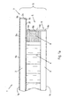
- Fig. 1a is a lightweight panel 1 having a top 1a, a bottom 1b and a plurality of narrow sides 1c, only one of which is shown here, wherein the lightweight panel has an upper cover layer 2, a lower cover layer 3 and therebetween a middle layer 4 of a cardboard honeycomb structure. Part of the middle layer 4 is also a arranged in the region of the narrow side 1c latch. 8
- the front edge 5 of the middle layer 4 and the front edge 6 of the lower cover layer 3 are completely opposite the end edge 7 of the upper cover layer 2 to the center of the lightweight board 1 reset, so that the upper cover layer 2 in the narrow side 1c with respect to the other layers 3 and 4 to the outside, here to the right, protrudes.
- a side facing away from the center of the lightweight panel 1 8 a side of the bolt 8 forms in this example, the front edge 5 of the central layer. 4
- the upper cover layer 2 is provided at the exposed portions 2a, 2b and 2c, that is, its upper side, its front edge and the protruding part of its underside, each with different coatings.
- the upper side 1a of the lightweight building board 1 or the upper side 2a of the upper cover layer 2 is provided with a first laminate 9a, the front edge with a safety edge 9b made of ABS and the lower side 2c with a second laminate 9c.
- the front edges 5 and 6 of the remaining layers 3 and 4 are coated with a common coating 9d, namely also a safety edge made of ABS.
- the dimensions of the component according to the invention can be selected as follows.
- the offset between the end edge 7 of the upper cover layer 2 and the end edges 5 and 6 of the remaining layers 3 and 4 may each be at least 10 mm, in particular at least 20 mm and preferably at least 40 mm.
- the thickness of the upper cover layer 2 and / or the lower cover layer 3 may be at least 6 mm, in particular at least 10 mm, and preferably at least 16 mm.
- the thickness of the central layer may be at least 10 mm, in particular at least 15 mm and preferably at least 20 mm. In the examples shown here, the offset between the end edges 7 and 5 and 6 respectively 20 mm, the thickness of the two cover layers 2 and 3 each 8 mm and the thickness of the central layer 4 22 mm.
- FIG. 1b An embodiment according to the present invention shows Fig. 1b).
- Fig. 1b differs from Fig. 1a ) in that in the ABS safety edge 9d, an LED strip 10 is integrated with a plurality of LEDs 10a.
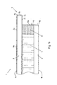
- Fig. 2a also shows a similar example of a lightweight board 1, in which the middle layer 4 but has no latch.
- the end edges 5 and 6 of the lower cover layer 3 and the middle layer 4 are covered by a profile 11 which has a substantially T-shaped cross-section.
- a toothed on one side first projection 11b extends from the end edges 5 and 6 covering part 11a to the center of the lightweight panel 1, on the other hand extends a second projection 11c at the upper end of the profile 11 of the part 17a in the direction the outer side of the lightweight panel 1.
- the projection 11c is elastic and forms a sealing lip, which rests against the underside of the upper cover layer 2.
- the profile 11 is made of a plastic that is so stiff that it can replace a bolt.
- FIG. 2b This in Fig. 2b ) shown further embodiment corresponds essentially to the in Fig. 2a ) illustrated example, with the difference that in the profile 11 additionally an LED strip 10 is integrated with a plurality of LEDs 10a.
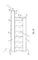
- Fig. 2c is also substantially the same as in FIG Fig. 2a ) example, here but with the difference that the profile 11 has no second projection 11c at the upper end, but engages with its upper end from below into a corresponding groove 12 which is provided in the upper cover layer 2 on the underside.
- An LED strip 10 with multiple LEDs 10a as shown in FIG Fig. 2b ), of course, also in the in Fig. 2c ) may be provided.
Description
Die Erfindung betrifft eine Leichtbauplatte mit einer Oberseite, einer Unterseite und mehreren Schmalseiten, enthaltend eine obere Decklage, eine untere Decklage, und eine zwischen der oberen Decklage und der unteren Decklage angeordnete Mittellage, wobei an zumindest einer der Schmalseiten des Bauteils die Stirnkanten der unterhalb der oberen Decklage angeordneten Lagen zumindest abschnittsweise gegenüber der Stirnkante der oberen Decklage zur Mitte des Bauteils hin zurückgesetzt sind und wobei die Stirnkanten der unterhalb der oberen Decklage angeordneten Lagen jeweils beschichtet sind.The invention relates to a lightweight board having an upper side, a lower side and a plurality of narrow sides, comprising an upper cover layer, a lower cover layer, and a middle layer arranged between the upper cover layer and the lower cover layer, wherein the front edges of at least one of the narrow sides of the component below upper cover layer arranged layers are at least partially opposite the end edge of the upper cover layer to the center of the component are set back and wherein the end edges of the arranged below the upper cover layer layers are respectively coated.
Der Einsatz von Leichtbauplatten (LBPL) im Innenausbau ist aus der Verwendung im Türenbau seit geraumer Zeit bekannt. In letzter Zeit hat die Leichtbauplatte aber auch im Küchenausbau verstärkt an Bedeutung gewonnen. Der Grund liegt hier einerseits in den vielfältigen Gestaltungsmöglichkeiten, die sich aufgrund der hohen Bauteildicken erzielen lassen, und zum Anderen am geringen Gewicht, was den Transport und die Montage der daraus hergestellten Arbeitsplatten wesentlich erleichtert.The use of lightweight panels (LBPL) in interior design has been known from the use in door construction for some time. Recently, however, the lightweight panel has also gained in importance in kitchen extension. The reason is here on the one hand in the various design options that can be achieved due to the high component thickness, and on the other hand, the low weight, which greatly facilitates the transport and assembly of the worktops made from it.
Mehrere Arbeitsgänge sind für die Herstellung einer als Küchenarbeitsplatte einsetzbaren Leichtbauplatte notwendig, die häufig sogar von Hand ausgeführt werden. Zunächst muss ein Rahmen hergestellt werden, eventuell mit mehreren Querriegeln, auf den dann die Decklagen aufgebracht werden. Zwischen den Decklagen werden Leichtfaserplatten, mineralische Dämmwolle, Kartonwaben oder ähnliches eingebracht. Damit wird dem Element mehr Kompaktheit und eventuell auch eine verbesserte Stabilität verliehen. Zumeist müssen in separaten Arbeitsgängen die Deckschichten auch noch oberflächenbehandelt werden. So sind als Decklagen furnierte oder anderweitig beschichtete Hartfaserplatten bekannt, wobei das fertige Element dann erst durch abschließendes Lackieren seine endgültige Oberfläche erhält.Several operations are necessary for the production of usable as a kitchen worktop lightweight board, which are often even performed by hand. First, a frame must be made, possibly with several crossbars on which then the top layers are applied. Between the cover layers lightweight fiber boards, mineral insulating wool, cardboard honeycomb or the like are introduced. This gives the item more compactness and possibly improved stability. In most cases, the outer layers must also be surface treated in separate operations. So are veneered or otherwise coated hardboard known as top layers, the finished element then receives its final surface only by final painting.
In jüngster Zeit werden Leichtbauplatten für den Einsatz als Arbeitsplatten in zunehmendem Maß auch industriell gefertigt. Dazu wird eine leichte Mittellage mit Decklagen versehen, zumeist durch Klebung, so dass ein großformatiger Verbund entsteht.Recently, lightweight panels for use as worktops increasingly also industrially manufactured. For this purpose, a light middle layer is provided with cover layers, usually by gluing, so that a large-scale composite arises.
Je nach geforderter Stabilität der Platte werden unterschiedlich dicke Decklagen, zumeist aus einem Holzwerkstoff wie Span- oder Faserplatte, eingesetzt. Die verwendeten Platten können bereits beschichtet sein, also etwa mit einem Laminat, einer Farbe, einem Druck mit Versiegelung, einer Melaminharzschicht, einem Furnier, etc. versehen sein.Depending on the required stability of the plate different thicknesses cover layers, mostly from a wood material such as chipboard or fiberboard used. The plates used may already be coated, that is to say be provided with a laminate, a paint, a pressure with a seal, a melamine resin layer, a veneer, etc.
Als Mittellagen werden bei Leichtbauplatten im Allgemeinen oder Schaumstoffplatten bevorzugt. Für bestimmte Verwendungszwecke sind möglicher Weise auch Wabenmaterialien aus anderen Materialien als Papier oder Karton sinnvoll. So können dafür dünnste Plattenmaterialien oder auch dünnwandiges Metall, beispielsweise aus Aluminium eingesetzt werden. Es ist aber auch möglich als Mittellagen leichte Holzwerkstoffe wie etwa entsprechende Spanplatten oder Faserplatten oder auch Massivholz geringer Dichte, wie Balsaholz, einzusetzen. Mit entsprechenden Ausnehmungen versehen sind grundsätzlich alle Materialien zum Einsatz als leichte Mittellage möglich. So werden dafür beispielsweise auch Holzarten herangezogen, die zwar nicht ein besonders geringes Gewicht aufweisen, dafür aber gut verfügbar sind und sich gut mit zerspanenden Werkzeugen bearbeiten lassen. Auch sind leichte Mittellagen aus Halmbündeln, die miteinander verbunden zu flächigen Gebilden aufgeschnitten werden, sodass dann die Länge der Halmabschnitte der Dicke der Mittellage entspricht, bekannt.As middle layers are preferred in lightweight panels in general or foam boards. Honeycomb materials made of materials other than paper or cardboard may also be useful for certain purposes. Thus, thinnest plate materials or even thin-walled metal, for example made of aluminum, can be used for this purpose. But it is also possible as middle layers of lightweight wood materials such as corresponding chipboard or Fiberboard or solid wood of low density, such as balsa wood, use. Provided with corresponding recesses are basically all materials for use as a light middle layer possible. For example, wood species are also used for this, which are not particularly light in weight, but are readily available and can be easily worked with cutting tools. Also, light middle layers of bundles of bundles, which are cut together to form flat structures, so that then the length of the stalk sections corresponds to the thickness of the middle layer known.
Bei. Küchenarbeitsplatten ist häufig eine relativ dünne Optik gewünscht, die eine Leichtbauplatte mit dem zuvor beschriebenen Aufbau nicht erfüllen kann. Holzwerkstoffe weisen dafür in der Regel nicht die ausreichende Stabilität auf, weswegen üblicherweise auf eher teure Granit- oder Compaktplatten zurückgegriffen wird.In. Kitchen countertops is often desired a relatively thin optics, which can not meet a lightweight panel with the structure described above. As a rule, wood-based materials do not have the sufficient stability, which is why it is customary to resort to more expensive granite or compact plates.
Eine Leichtbauplatte mit einer oberen Decklage, einer unteren Decklage und einer dazwischen angeordneten Mittellage, bei der die Mittellage und die untere Decklage so ausgebildet sind, dass deren Stirnkanten gegenüber der Stirnkante der oberen Decklage zur Mitte des Bauteils hin zurückgesetzt sind, ist beispielsweise bekannt aus der
Es ist daher die Aufgabe der vorliegenden Erfindung, eine Leichtbauplatte zu schaffen, die eine Alternative zum vorangehend beschriebenen Stand der Technik bereitstellt.It is therefore the object of the present invention to provide a lightweight board which provides an alternative to the prior art described above.
Die zuvor hergeleitete und aufgezeigte Aufgabe wird bei einer Leichtbauplatte der eingangs genannten Art dadurch gelöst, dass die Beschichtung von einem LED-Band oder einem integrierte LEDs aufweisenden Profil gebildet wird. Mit den unterhalb der oberen Decklage angeordneten Lagen sind die übrigen Lagen im Plattenaufbau gemeint, die also bei einer horizontalen Ausrichtung des Bauteils, das heißt der Leichtbauplatte, vertikal unter der oberen Decklage angeordnet sind. Die Stirnkanten der unterhalb der oberen Decklage angeordneten Lagen brauchen nicht zwangsläufig vollständig, das heißt über die gesamte Breite bzw. Länge des Bauteils, zurückgesetzt sein, sondern können im Bedarfsfall auch nur in einem oder mehreren Abschnitten zurückgesetzt sein. Es sei darauf hingewiesen, dass der Versatz zwischen der Stirnkante der oberen Decklage und der Stirnkante der Mittellage nicht identisch mit dem Versatz zwischen der Stirnkante der oberen Decklage und der Stirnkante der unteren Decklage sein muss. Im Gegenteil, die Stirnkante der Mittellage kann auch weiter oder weniger weit als die Stirnkante der unteren Decklage zurückgesetzt sein.The previously derived and indicated object is achieved in a lightweight panel of the type mentioned above in that the coating is formed by an LED strip or integrated LEDs having profile. With the layers arranged below the upper cover layer, the remaining layers in the plate structure are meant, which are thus arranged vertically below the upper cover layer in the case of a horizontal alignment of the component, that is to say the lightweight building board. The end edges of the layers arranged below the upper cover layer need not necessarily be completely reset, that is to say over the entire width or length of the component, but can, if required, also be reset in only one or more sections. It should be noted that the offset between the front edge of the upper cover layer and the front edge of the central layer does not have to be identical to the offset between the front edge of the upper cover layer and the front edge of the lower cover layer. On the contrary, the front edge of the middle layer may also be set back more or less far than the front edge of the lower cover layer.
Indem die Stirnkanten der übrigen Lagen des Bauteils, bei dem es sich auch um eine mehrlagige Holzwerkstoffplatte mit einer Mittellage aus vorzugsweise Vollspan handeln kann, zurückgesetzt sind, die obere Decklage also gegenüber diesen übrigen Lagen nach außen hervorsteht, d.h. einen Überstand hat, wird die Optik einer relativ dünnen Arbeitsplatte erzielt. Vorzugsweise wird das Bauteil so eingebaut oder verkleidet bzw. beschichtet - letzteres wird im Folgenden noch näher erläutert -, dass im bestimmungsgemäß eingebauten Zustand des Bauteils nur noch die obere Decklage sichtbar ist bzw. als Arbeitsplatte vom Benutzer wahrgenommen wird. Der die obere Decklage tragende Aufbau, der die übrigen Lagen des Bauteils umfasst, ist für den Benutzer auf diese Weise nicht mehr als Teil der Platte wahrnehmbar, sondern wird, so überhaupt sichtbar, allenfalls als Sockel wahrgenommen. Dieser Eindruck kann dadurch noch verstärkt werden, dass die obere Decklage anders, insbesondere mit einem anderen Material, beschichtet wird als der übrige Teil des Bauteils. Gleichzeitig hat das Bauteil beim Einsatz als Küchenarbeitsplatte weiterhin die positiven Eigenschaften, insbesondere die Stabilität, einer herkömmlichen Leichtbauplatte.By the front edges of the other layers of the component, which may also be a multi-layer wood-based panel with a central layer of preferably full chip, are reset, so the upper cover layer so protrudes outwardly from these other layers, ie has a supernatant, the appearance of a relatively thin worktop is achieved. Preferably, the component is installed or clad or coated - the latter will be explained in more detail below - that in the intended installed condition of the component only the upper cover layer is visible or is perceived as a countertop by the user. The upper cover layer supporting structure comprising the other layers of the component is no longer perceptible to the user in this way as part of the plate, but will, if any visible, possibly perceived as a pedestal. This impression can be exacerbated by the fact that the upper cover layer is coated differently, in particular with a different material, than the remaining part of the component. At the same time, when used as a kitchen worktop, the component still has the positive properties, in particular the stability, of a conventional lightweight building board.
Gemäß einer Ausgestaltung der erfindungsgemäßen Leichtbauplatte weist die Mittellage einen oder mehrere Riegel auf, die vorzugsweise über die gesamte Breite oder Länge des Bauteils verlaufen. Bei mindestens einem Riegel kann eine von der Mitte des Bauteils abgewandte Seite des Riegels zumindest einen Teil der Stirnkante der Mittellage bilden. Bei einer Leichtbauplatte ist ein Riegel insbesondere dann von Vorteil, wenn die unterhalb der oberen Decklage angeordneten Lagen der Umgebung ausgesetzt sind und insbesondere einen Sockel bilden. In diesem Fall erhöht der Riegel nicht nur die Stabilität der unterhalb der oberen Decklage angeordneten Lagen, insbesondere der Mittellage, sondern schützt diese auch vor Feuchtigkeit und Stößen. Ein Riegel kann auch, wie im Folgenden noch beschrieben wird, dazu verwendet werden, die Beschichtung, insbesondere ein Profil, auf die Mittellage aufzubringen. Es ist aber auch denkbar, das Bauteil, das heißt die Leichtbauplatte, ohne Riegel auszuführen.According to one embodiment of the lightweight panel according to the invention, the central layer on one or more bars, which preferably extend over the entire width or length of the component. In at least one bolt, a side of the bolt facing away from the center of the component can form at least a part of the front edge of the middle position. In a lightweight board, a bolt is particularly advantageous if the layers arranged below the upper cover layer are exposed to the environment and in particular form a base. In this case, the bolt not only increases the stability of the layers arranged below the upper cover layer, in particular the middle layer, but also protects it from moisture and shocks. A bolt can also, as will be described below, be used to apply the coating, in particular a profile, to the middle layer. But it is also conceivable to carry out the component, that is the lightweight board, without a bolt.
Gemäß noch einer weiteren Ausgestaltung der erfindungsgemäßen Leichtbauplatte ist die obere Decklage zumindest abschnittsweise, insbesondere zumindest an einem oder mehreren der freiliegenden Abschnitte, beschichtet. Mit den freiliegenden Abschnitten sind die Abschnitte der oberen Decklage gemeint, die der Umgebung ausgesetzt sind und nicht von der Mittellage abgedeckt sind. Es ist aber auch denkbar, dass die obere Decklage vollständig beschichtet ist. Vorzugsweise sind zumindest diejenigen Abschnitte beschichtet, die für den Benutzer sichtbar sind und mit Feuchtigkeit und Schmutz in Kontakt kommen, also insbesondere die Oberseite und die Stirnkante der oberen Decklage.According to yet another embodiment of the lightweight board according to the invention, the upper cover layer is at least partially coated, in particular at least on one or more of the exposed sections. By exposed sections are meant the portions of the top cover layer which are exposed to the environment and are not covered by the central layer. But it is also conceivable that the upper cover layer is completely coated. Preferably, at least those portions are coated, which are visible to the user and come into contact with moisture and dirt, ie in particular the top and the front edge of the upper cover layer.
Erfindungsgemäß ist wie gesagt die Stirnkante der Mittellage bzw. - wenn ein Riegel die Mittellage abschließt - die die Stirnkante bildende Seite des Riegels der Mittellage beschichtet. Dabei sind sämtliche Stirnkanten der unterhalb der oberen Decklage angeordneten Lagen jeweils beschichtet. Diese Beschichtung kann wie gesagt den Eindruck einer dünnen Optik verstärken, da der unterhalb der oberen Decklage angeordnete Teil des Bauteils somit optisch deutlich gegenüber der oberen Decklage abgesetzt ist.According to the invention, as stated, the front edge of the middle layer or - if a bolt closes the middle layer - the end edge forming side of the bolt of the middle layer coated. In this case, all end edges of the layers arranged below the upper cover layer are each coated. As already mentioned, this coating can reinforce the impression of a thin appearance since the part of the component arranged below the upper cover layer is thus optically distinct from the upper cover layer.
Gemäß einer weiteren Ausgestaltung der erfindungsgemäßen Leichtbauplatte weisen zumindest einige der beschichteten Abschnitte der oberen Decklage und/oder der unterhalb der oberen Decklage angeordneten Lagen unterschiedliche Beschichtungen auf. Es können aber sowohl an der oberen Decklage als auch an den unterhalb der oberen Decklage angeordneten Lagen Abschnitte mit der gleichen Beschichtung vorgesehen sein. Vorzugsweise weisen die Stirnkanten der unterhalb der oberen Decklage angeordneten Lagen eine gemeinsame Beschichtung auf, also eine.Beschichtung, die insbesondere durchgängig vorgesehen ist.According to a further embodiment of the lightweight board according to the invention, at least some of the coated Sections of the upper cover layer and / or the layers arranged below the upper cover layer have different coatings. However, sections with the same coating can be provided both on the upper cover layer and on the layers arranged below the upper cover layer. The front edges of the layers arranged below the upper cover layer preferably have a common coating, that is to say a coating which is provided in particular continuously.
Es sind verschiedene Möglichkeiten denkbar, die Beschichtung zu bilden.There are various possibilities conceivable to form the coating.
So kann die Beschichtung gemäß einer ersten Alternative von einem LED-Band gebildet werden, also einem festen oder flexiblen Streifen, beispielsweise Kunststoffstreifen, in den eine Vielzahl von LEDs, fertig verdrahtet, eingebettet ist.Thus, according to a first alternative, the coating may be formed by an LED strip, ie a solid or flexible strip, for example plastic strip, into which a multiplicity of LEDs, ready-wired, are embedded.
Die Beschichtung kann aber auch von einem Profil gebildet werden, wobei das Profil vorzugsweise einen die Stirnkanten der unterhalb der oberen Decklage angeordneten Lagen abdeckenden Teil aufweist. In diesem Fall ist ein Riegel zum Schutz der Mittellage, insbesondere im Falle einer Leichtbauplatte, nicht mehr nötig, kann aber aus Stabilitätsgründen dennoch vorgesehen sein. Das Profil kann einen zur Mitte des Bauteils weisenden Vorsprung, der insbesondere zumindest an einer Seite, beispielsweise der zur unteren Decklage gewandten Seite, gezahnt ist und vorzugsweise zwischen der Mittellage und der unteren Decklage angeordnet ist, aufweisen. Mit einem solchen Vorsprung kann das Profil optimal in dem Bauteil, das heißt der Leichtbauplatte, fixiert werden. Dabei kann das Profil auch einen von der Mitte des Bauteils wegweisenden Vorsprung aufweisen, der insbesondere an der Unterseite der oberen Decklage anliegt. Dieser Vorsprung, der vorzugsweise elastisch ausgebildet ist, bildet vorzugsweise eine Dichtlippe und verhindert das Eindringen von Schmutz und Feuchtigkeit ins Innere des Bauteils, insbesondere in die Mittellage. Auch kann vorgesehen sein, dass das Profil in eine Nut an der Unterseite der oberen Decklage eingreift, was einerseits eine verbesserte Fixierung des Profils an dem Bauteil und andererseits auch eine Abdichtung gewährleistet.However, the coating can also be formed by a profile, wherein the profile preferably has a part covering the end edges of the layers arranged below the upper cover layer. In this case, a bolt to protect the middle layer, especially in the case of a lightweight board, no longer necessary, but may still be provided for stability reasons. The profile can have a projection facing the center of the component, which is in particular toothed on at least one side, for example the side facing the lower cover layer, and is preferably arranged between the middle layer and the lower cover layer. With such a projection, the profile can be optimally fixed in the component, that is, the lightweight board. The profile can also have a pointing away from the center of the component projection, which bears in particular on the underside of the upper cover layer. This projection, which is preferably elastic, preferably forms a sealing lip and prevents the penetration of dirt and moisture into the interior of the component, in particular into the middle position. It can also be provided that the profile engages in a groove on the underside of the upper cover layer, which on the one hand ensures improved fixation of the profile on the component and on the other hand also a seal.
Bei der letztgenannten Alternative der erfindungsgemäßen Leichtbauplatte sind LEDs in die Beschichtung, die von dem Profil gebildet wird, integriert. Dabei kann es sich um einzelne LEDs handeln, aber auch um ein wie zuvor beschriebenes LED-Band. Insbesondere bei einer Leichtbauplatte ist, im Gegensatz zu Vollspan, die Anbringung von LEDs besonders einfach, da die Netzkabel sehr leicht durch die Mittellage, insbesondere Kartonwabe, geführt werden können.In the latter alternative of the lightweight board according to the invention LEDs are integrated into the coating, which is formed by the profile. These can be individual LEDs, but also an LED band as described above. In particular, in a lightweight board, in contrast to full chip, the attachment of LEDs is particularly simple, since the power cord can be very easily through the middle layer, in particular cardboard honeycomb, performed.
Das Material der jeweiligen Beschichtung ist gemäß wiederum einer weiteren Ausgestaltung der erfindungsgemäßen Leichtbauplatte gewählt aus der Gruppe enthaltend Glas, Metall, insbesondere Aluminium oder Chrom, Kunststoff, insbesondere ABS (Acrylnitril-Butadien-Acrylat) oder PP (Polypropylen), und Schichtstoff, insbesondere mit mindestens einem harzgetränkten Papier. Diese Materialien können optisch hochwertige sowie schlag- und kratzfeste Zierleisten bilden.The material of the respective coating is again selected according to a further embodiment of the lightweight board according to the invention from the group containing glass, metal, in particular aluminum or chromium, plastic, in particular ABS (acrylonitrile-butadiene-acrylate) or PP (polypropylene), and laminate, in particular with at least one resin-impregnated paper. These materials can form visually high-quality as well as impact and scratch-resistant trim.
Erfindungsgemäß weist zumindest eine der Decklagen einen Holzwerkstoff, insbesondere eine Span-, Faser- oder OSB-Platte (Oriented-Strands-Board), auf.According to the invention, at least one of the cover layers has a Wood material, in particular a chip, fiber or OSB board (Oriented Strands Board), on.
Die Dicke zumindest der oberen Decklage, also zumindest der Decklage mit dem Überstand, kann in einem Bereich bis 16 mm, insbesondere bis 10 mm, vorzugsweise bis 6 mm, liegen. Die Länge des Überstands, d.h. des Versatzes zwischen Stirnkante der oberen Decklage und Stirnkante der Mittellage und/oder unteren Decklage, kann mindestens 10 mm, insbesondere mindestens 20 mm, vorzugsweise mindestens 40 mm, betragen. Um eine optimale Stabilität des überstehenden Teils der oberen Deckplatte zu erreichten, ist es bevorzugt, wenn die Dicke der oberen Deckplatte und die Länge des Überstands aufeinander abgestimmt sind. So ist es vorteilhaft, wenn die Länge des Überstands höchstens das 3-fache, insbesondere höchstens das 2,5-fache, vorzugsweise höchstens das 2-fache, der Dicke der oberen Deckplatte beträgt.The thickness of at least the upper cover layer, ie at least the cover layer with the supernatant, can be in a range up to 16 mm, in particular up to 10 mm, preferably up to 6 mm. The length of the supernatant, i. the offset between the front edge of the upper cover layer and the front edge of the middle layer and / or lower cover layer may be at least 10 mm, in particular at least 20 mm, preferably at least 40 mm. In order to achieve optimum stability of the protruding part of the upper cover plate, it is preferred if the thickness of the upper cover plate and the length of the supernatant are coordinated. Thus, it is advantageous if the length of the supernatant is at most 3 times, in particular at most 2.5 times, preferably at most 2 times, the thickness of the upper cover plate.
Gemäß noch einer weiteren Ausgestaltung der erfindungsgemäßen Leichtbauplatte weist die Mittellage eine Wabenstruktur, insbesondere Kartonwabenstruktur, und/oder einen Holzwerkstoff, der insbesondere wie zuvor beschrieben ausgebildet sein kann, auf.According to yet another embodiment of the lightweight building panel according to the invention, the middle layer has a honeycomb structure, in particular a cardboard honeycomb structure, and / or a wood material, which may be designed in particular as described above.
Es gibt nun eine Vielzahl von Möglichkeiten, die erfindungsgemäße Leichtbauplatte auszugestalten und weiterzubilden. Hierzu sei einerseits verwiesen auf die dem Patentanspruch 1 nachgeordneten Patentansprüche, andererseits auf die Beschreibung von Ausführungsbeispielen in Verbindung mit der Zeichnung. In der Zeichnung zeigt:
- Fig. 1a)
- eine Schnittansicht einer Leichtbauplatte, die nicht Gegenstand der Erfindung ist,
- Fig. 1b)
- eine Schnittansicht eines ersten Ausführungsbeispiels einer Leichtbauplatte gemäß der vorliegenden Erfindung,
- Fig. 2a)
- eine Schnittansicht einer Leiclutbauplatte, die nicht Gegenstand der Erfindung ist,
- Fig. 2b)
- eine Schnittansicht eines zweiten Ausführungsbeispiels einer Leichtbauplatte gemäß der vorliegenden Erfindung, und
- Fig. 2c)
- eine Schnittansicht einer Leichtbauplatte, die auch nicht Gegenstand der Erfindung ist.
- Fig. 1a)
- a sectional view of a lightweight board, which is not the subject of the invention,
- Fig. 1b)
- a sectional view of a first embodiment of a lightweight panel according to the present invention,
- Fig. 2a)
- a sectional view of a Leiclutbauplatte, which is not the subject of the invention,
- Fig. 2b)
- a sectional view of a second embodiment of a lightweight panel according to the present invention, and
- Fig. 2c)
- a sectional view of a lightweight panel, which is not the subject of the invention.
Die
In
An der dargestellten Schmalseite 1c der Leichtbauplatte 1 sind die Stirnkante 5 der Mittellage 4 und die Stirnkante 6 der unteren Decklage 3 vollständig gegenüber der Stirnkante 7 der oberen Decklage 2 zur Mitte der Leichtbauplatte 1 hin zurückgesetzt, so dass die obere Decklage 2 im Bereich der Schmalseite 1c gegenüber den übrigen Lagen 3 und 4 nach außen, hier nach rechts, hervorsteht.On the illustrated narrow side 1c of the lightweight board 1, the
Eine von der Mitte der Leichtbauplatte 1 abgewandte Seite 8a des Riegels 8 bildet in diesem Beispiel die Stirnkante 5 der Mittellage 4.A side facing away from the center of the lightweight panel 1 8 a side of the
Die obere Decklage 2 ist an den freiliegenden Abschnitten 2a, 2b und 2c, das heißt ihrer Oberseite, ihrer Stirnkante und dem hervorstehenden Teil ihrer Unterseite, mit jeweils unterschiedlichen Beschichtungen versehen. Die Oberseite 1a der Leichtbauplatte 1 bzw. die Oberseite 2a der oberen Decklage 2 ist mit einem ersten Schichtstoff 9a, die Stirnkante mit einer Sicherheitskante 9b aus ABS und die Unterseite 2c mit einem zweiten Schichtstoff 9c versehen. Die Stirnkanten 5 und 6 der übrigen Lagen 3 und 4 sind mit einer gemeinsamen Beschichtung 9d, nämlich ebenfalls einer Sicherheitskante aus ABS, beschichtet.The
Die Abmessungen des erfindungsgemäßen Bauteils, nämlich der Leichtbauplatte 1, können wie folgt gewählt werden. Der Versatz zwischen der Stirnkante 7 der oberen Decklage 2 und den Stirnkanten 5 und 6 der übrigen Lagen 3 und 4 kann jeweils mindestens 10 mm, insbesondere mindestens 20 mm und vorzugsweise mindestens 40 mm betragen. Die Dicke der oberen Decklage 2 und/oder der unteren Decklage 3 kann mindestens 6 mm, insbesondere mindestens 10 mm und vorzugsweise mindestens 16 mm betragen. Die Dicke der Mittellage kann mindestens 10 mm, insbesondere mindestens 15 mm und vorzugsweise mindestens 20 mm betragen. In den hier dargestellten Beispielen beträgt der Versatz zwischen den Stirnkanten 7 und 5 bzw. 6 jeweils 20 mm, die Dicke der beiden Decklagen 2 und 3 jeweils 8 mm und die Dicke der Mittellage 4 22 mm.The dimensions of the component according to the invention, namely the lightweight panel 1, can be selected as follows. The offset between the
Ein Ausführungsbeispiel gemäß der vorliegenden Erfindung zeigt
Im dargestellten Beispiel ist lediglich ein zur Mitte der Leichtbauplatte 1 weisender Vorsprung 11d vorgesehen. Es ist aber auch denkbar, dass noch ein weiterer, paralleler Vorsprung auf der dem die Dichtlippe bildenden Vorsprung gegenüberliegenden Seite vorgesehen ist, der ebenfalls gezahnt sein kann. Bei zwei Vorsprüngen kann das Profil noch besser verankert werden.In the example shown, only one pointing to the center of the lightweight panel 1 projection 11d is provided. But it is also conceivable that another, parallel projection on the side opposite the lip forming the projection side is provided, which also can be toothed. With two projections, the profile can be anchored even better.
Die Abmessungen dieses Beispiels stimmen mit den Abmessungen des in
Das in
Schließlich entspricht das in
Ein LED-Band 10 mit mehreren LEDs 10a, wie dies in
Claims (8)
- A lightweight board (1), having an upper side (1a), an underside (1b) and a plurality of narrow sides (1c), containing:- an upper covering layer (2),- a lower covering layer (3), and- a centre layer (4) arranged between the upper covering layer (2) and the lower covering layer (3),- wherein at least one of the covering layers (2, 3) has a wood-based material,- wherein on at least one of the narrow sides (1c) of the structural component the end edges (5, 6) of the layers (3, 4) arranged underneath the upper covering layer (2) are set back towards the centre of the structural component in relation to the end edge (7) of the upper covering layer (2), at least in some sections, and- wherein the end edges (5, 6) of the layers (3, 4) arranged underneath the upper covering layer (2) are each coated, characterised in that the coating (9d) is formed by an LED strip (10) or a profile (11) having integrated LEDs (10a).
- The lightweight board (1) according to claim 1, characterised in that the centre layer (4) has one or more bars (8), which preferably run over the entire width or length of the lightweight board (1), wherein in particular in the case of at least one bar (8) a side (8a) of the bar (8) facing away from the centre of the lightweight board (1) forms at least part of the end edge (5) of the centre layer (4).
- The lightweight board (1) according to any one of the preceding claims, characterised in that the upper covering layer (2) is coated, at least in some sections, in particular at least on one or more exposed sections (2a, 2b, 2c), preferably completely.
- The lightweight board (1) according to any one of the preceding claims, characterised in that the profile (11) has a projection (11b), which points towards the centre of the structural component and in particular is toothed on at least one side and is preferably arranged between the centre layer (4) and the lower covering layer (3).
- The lightweight board (1) according to any one of the preceding claims, characterised in that the profile (11) has a projection (11c), which points away from the centre of the structural component and in particular bears against the underside of the upper covering layer (2).
- The lightweight board (1) according to any one of the preceding claims, characterised in that the profile (11) engages in a groove (12) on the underside of the upper covering layer (2).
- The lightweight board (1) according to any one of the preceding claims, characterised in that the material of the respective coating (9a, 9b, 9c, 9d) is selected from the group containing glass, metal, in particular aluminium or chromium, plastic, in particular ABS or PP, and laminate, in particular having at least one resin-impregnated paper.
- The lightweight board (1) according to any one of the preceding claims, characterised in that the centre layer (4) has a honeycomb structure, in particular cardboard honeycomb structure, and/or a wood-based material.
Priority Applications (1)
| Application Number | Priority Date | Filing Date | Title |
|---|---|---|---|
| PL09802135T PL2379321T3 (en) | 2009-01-16 | 2009-12-21 | Component, in particular lightweight panel |
Applications Claiming Priority (2)
| Application Number | Priority Date | Filing Date | Title |
|---|---|---|---|
| DE102009005316A DE102009005316A1 (en) | 2009-01-16 | 2009-01-16 | Component, in particular lightweight panel |
| PCT/EP2009/067649 WO2010081615A1 (en) | 2009-01-16 | 2009-12-21 | Component in particular lightweight panel |
Publications (2)
| Publication Number | Publication Date |
|---|---|
| EP2379321A1 EP2379321A1 (en) | 2011-10-26 |
| EP2379321B1 true EP2379321B1 (en) | 2014-04-16 |
Family
ID=41674162
Family Applications (1)
| Application Number | Title | Priority Date | Filing Date |
|---|---|---|---|
| EP09802135.5A Active EP2379321B1 (en) | 2009-01-16 | 2009-12-21 | Component, in particular lightweight panel |
Country Status (8)
| Country | Link |
|---|---|
| EP (1) | EP2379321B1 (en) |
| DE (1) | DE102009005316A1 (en) |
| ES (1) | ES2469817T3 (en) |
| PL (1) | PL2379321T3 (en) |
| PT (1) | PT2379321E (en) |
| RU (1) | RU2520562C2 (en) |
| UA (1) | UA98091C2 (en) |
| WO (1) | WO2010081615A1 (en) |
Cited By (1)
| Publication number | Priority date | Publication date | Assignee | Title |
|---|---|---|---|---|
| CN109666215A (en) * | 2018-12-06 | 2019-04-23 | 江苏科技大学 | A kind of high-intensity hollow composite material building mould board and its processing method and recovery method |
Families Citing this family (4)
| Publication number | Priority date | Publication date | Assignee | Title |
|---|---|---|---|---|
| EP2893101B1 (en) * | 2012-09-07 | 2021-04-07 | ZÜBLIN Timber Aichach GmbH | Multi-layered timber panel |
| DE202015102210U1 (en) * | 2015-04-30 | 2016-08-02 | Rehau Ag + Co. | furniture board |
| FR3037858B1 (en) * | 2015-06-29 | 2017-08-18 | Airbus Defence & Space Sas | COMPOSITE PANEL AND MECHANICAL CONNECTION FOR SUCH A PANEL |
| DE102018216818B4 (en) * | 2018-09-28 | 2020-04-16 | Schott Ag | Worktop as well as a work table comprising a worktop |
Citations (1)
| Publication number | Priority date | Publication date | Assignee | Title |
|---|---|---|---|---|
| DE20314832U1 (en) * | 2003-09-23 | 2004-02-26 | Meck, Thorsten | Worktop with lighting |
Family Cites Families (21)
| Publication number | Priority date | Publication date | Assignee | Title |
|---|---|---|---|---|
| DE2550324A1 (en) * | 1975-11-08 | 1977-05-18 | Spannbetonwerk Koch Kg | Laminated panel for roofs, ceilings and walls - with framework of longitunidal and transverse ribs |
| DE7804594U1 (en) * | 1978-02-16 | 1978-06-15 | Gebr. Knauf Westdeutsche Gipswerke, 8715 Iphofen | FLOORING PANEL |
| DE2945752A1 (en) * | 1979-11-13 | 1981-05-21 | Fritz Reinke Engineering, 6122 Erbach | METHOD AND DEVICE FOR PRODUCING COMPOSITE BUILDING BOARDS |
| DE8017134U1 (en) * | 1979-12-10 | 1980-11-20 | Cloisall, S.A., Bruessel | PARTITION |
| DE4100796C2 (en) * | 1991-01-12 | 1995-06-14 | Kurt Dipl Ing Karl | Lightweight element |
| DE20004961U1 (en) * | 2000-03-17 | 2000-05-31 | Rational Einbaukuechen Gmbh | Worktop for a kitchen or bathroom furniture |
| DE10201722A1 (en) * | 2002-01-18 | 2003-07-31 | Kellner Peter | Composite natural stone slab, has reinforcing layer bonded to slab and lightweight material layer via adhesive layers |
| ITPD20020090A1 (en) | 2002-04-11 | 2003-10-13 | Quadrifoglio Di Paola Cozza E | TAMBOURED PANEL STRUCTURE |
| DE202004004185U1 (en) * | 2004-03-16 | 2005-07-28 | Schwanekamp Gmbh | Kitchen work plate for use in sanitary area, has supporting layer connected with one side of protective layer, and supporting unit connected with protective layer and arranged adjacent to border of protective layer |
| DE202004016976U1 (en) * | 2004-11-04 | 2005-01-13 | Natursteine Gebhard Schick Handels Gmbh | Kitchen work surface has transparent profile mounted under its front edge, inside which strip of highly electroluminescent light-emitting diodes is mounted |
| DE102004053881B4 (en) * | 2004-11-04 | 2008-11-13 | Ima Klessmann Gmbh Holzbearbeitungssysteme | Method for producing formatted lightweight panels |
| DE202004017690U1 (en) * | 2004-11-16 | 2005-02-17 | Naturstein Jäschke GmbH | Cover plate e.g. for furniture items, has one or several light sources arranged over complete length of rear front face |
| DE202005003808U1 (en) * | 2005-02-04 | 2006-06-14 | Lipp, Magnus | Building part for ceilings or walls of houses has first layer of expandable tension-bearing material and second layer of non-compactable pressure-resistant material topped by covering layer resting on frame |
| RU56927U1 (en) * | 2006-04-21 | 2006-09-27 | Николай Васильевич Сидоров | LIGHTING CONSTRUCTION PROFILE |
| DE102006038115B4 (en) | 2006-08-14 | 2019-01-24 | Fritz Egger Gmbh & Co. Og | Lightweight panel and method for its production |
| DE202006019672U1 (en) * | 2006-12-19 | 2007-03-08 | STRÄHLE Raum - Systeme GmbH | Wall unit for use in partition wall system, has frame units with groove at outer side, in which textile material is partially utilized by profile stripe, where area between base plate and material is filled with sound absorbing material |
| DE102007018128A1 (en) * | 2007-04-16 | 2008-10-30 | Resul Senol | Möbelabdeckplatte |
| RU71666U1 (en) * | 2007-11-27 | 2008-03-20 | Олег Николаевич Щербаков | LIGHTING BUILDING PANEL |
| DE102008009767B3 (en) * | 2008-02-19 | 2009-09-24 | Homag Holzbearbeitungssysteme Ag | Method and device for refining a workpiece |
| RU76671U1 (en) * | 2008-05-14 | 2008-09-27 | Игорь Эдуардович Мкртычев | LIGHT-BEARING PROFILE FOR TRADE AND EXHIBITION EQUIPMENT |
| DE202009004509U1 (en) * | 2009-03-27 | 2009-06-25 | Jankowski, Robert | Natural, art stone light plate |
-
2009
- 2009-01-16 DE DE102009005316A patent/DE102009005316A1/en not_active Ceased
- 2009-12-21 PT PT98021355T patent/PT2379321E/en unknown
- 2009-12-21 ES ES09802135.5T patent/ES2469817T3/en active Active
- 2009-12-21 WO PCT/EP2009/067649 patent/WO2010081615A1/en active Application Filing
- 2009-12-21 PL PL09802135T patent/PL2379321T3/en unknown
- 2009-12-21 RU RU2011134256/04A patent/RU2520562C2/en active
- 2009-12-21 UA UAA201108930A patent/UA98091C2/en unknown
- 2009-12-21 EP EP09802135.5A patent/EP2379321B1/en active Active
Patent Citations (1)
| Publication number | Priority date | Publication date | Assignee | Title |
|---|---|---|---|---|
| DE20314832U1 (en) * | 2003-09-23 | 2004-02-26 | Meck, Thorsten | Worktop with lighting |
Cited By (2)
| Publication number | Priority date | Publication date | Assignee | Title |
|---|---|---|---|---|
| CN109666215A (en) * | 2018-12-06 | 2019-04-23 | 江苏科技大学 | A kind of high-intensity hollow composite material building mould board and its processing method and recovery method |
| CN109666215B (en) * | 2018-12-06 | 2021-11-12 | 江苏科技大学 | High-strength hollow composite material building template and processing method and recycling method thereof |
Also Published As
| Publication number | Publication date |
|---|---|
| PL2379321T3 (en) | 2014-09-30 |
| DE102009005316A1 (en) | 2010-07-22 |
| WO2010081615A1 (en) | 2010-07-22 |
| EP2379321A1 (en) | 2011-10-26 |
| PT2379321E (en) | 2014-06-23 |
| ES2469817T3 (en) | 2014-06-20 |
| RU2520562C2 (en) | 2014-06-27 |
| RU2011134256A (en) | 2013-02-27 |
| UA98091C2 (en) | 2012-04-10 |
Similar Documents
| Publication | Publication Date | Title |
|---|---|---|
| EP2379321B1 (en) | Component, in particular lightweight panel | |
| DE202019005313U1 (en) | Furniture plate with integrated mounting element for a movement fitting and furniture body and furniture with such a furniture plate | |
| EP2051848B1 (en) | Lightweight panel | |
| EP2016237B1 (en) | Sealing element for a lightweight structural panel | |
| EP2525010B1 (en) | Lightweight construction, method and device for manufacture of the lightweight construction | |
| AT509896B1 (en) | LAYER PLATE | |
| DE102007054932B4 (en) | furniture board | |
| DE202004012141U1 (en) | Plate for furniture, floors and similar items comprises at least one stiffening element which is located under the cover layers and consists of a light-weight building material | |
| EP1969967B1 (en) | Furniture top, in particular solid wood top | |
| EP2147778B1 (en) | Light construction board for furniture construction | |
| EP1217143B1 (en) | Step assembly for staircases | |
| EP2403712B1 (en) | Lightweight building board and method and device for the production thereof | |
| EP2170599A1 (en) | Lightweight building panel | |
| DE102017001477B4 (en) | countertop | |
| DE102011107830B4 (en) | Sandwich panel, in particular for furniture, and manufacturing method | |
| EP2653069B1 (en) | Furniture structure | |
| EP3754128B1 (en) | Acoustic panel with offset grooves | |
| DE4337474A1 (en) | Door-leaf construction | |
| EP2907958B1 (en) | Method for manufacturing of door wings | |
| DE202011000752U1 (en) | Furniture panel, especially furniture front panel | |
| DE202017000815U1 (en) | Wood panel | |
| DE6904143U (en) | COMPOSITE PLATE | |
| DE102012021526A1 (en) | Support frame for kitchen worktop device for use with e.g. cabinet, has frame opening for accommodating lightweight panel, where lightweight panel is firmly connected with surface against inner side of frame |
Legal Events
| Date | Code | Title | Description |
|---|---|---|---|
| PUAI | Public reference made under article 153(3) epc to a published international application that has entered the european phase |
Free format text: ORIGINAL CODE: 0009012 |
|
| 17P | Request for examination filed |
Effective date: 20110314 |
|
| AK | Designated contracting states |
Kind code of ref document: A1 Designated state(s): AT BE BG CH CY CZ DE DK EE ES FI FR GB GR HR HU IE IS IT LI LT LU LV MC MK MT NL NO PL PT RO SE SI SK SM TR |
|
| DAX | Request for extension of the european patent (deleted) | ||
| 17Q | First examination report despatched |
Effective date: 20121024 |
|
| RIC1 | Information provided on ipc code assigned before grant |
Ipc: B32B 3/02 20060101AFI20130930BHEP Ipc: B32B 3/12 20060101ALN20130930BHEP Ipc: A47B 96/20 20060101ALI20130930BHEP Ipc: B32B 21/00 20060101ALN20130930BHEP |
|
| RIC1 | Information provided on ipc code assigned before grant |
Ipc: B32B 3/12 20060101ALN20131009BHEP Ipc: B32B 3/02 20060101AFI20131009BHEP Ipc: A47B 96/20 20060101ALI20131009BHEP Ipc: B32B 21/00 20060101ALN20131009BHEP |
|
| GRAP | Despatch of communication of intention to grant a patent |
Free format text: ORIGINAL CODE: EPIDOSNIGR1 |
|
| INTG | Intention to grant announced |
Effective date: 20131126 |
|
| GRAS | Grant fee paid |
Free format text: ORIGINAL CODE: EPIDOSNIGR3 |
|
| GRAA | (expected) grant |
Free format text: ORIGINAL CODE: 0009210 |
|
| AK | Designated contracting states |
Kind code of ref document: B1 Designated state(s): AT BE BG CH CY CZ DE DK EE ES FI FR GB GR HR HU IE IS IT LI LT LU LV MC MK MT NL NO PL PT RO SE SI SK SM TR |
|
| REG | Reference to a national code |
Ref country code: GB Ref legal event code: FG4D Free format text: NOT ENGLISH |
|
| REG | Reference to a national code |
Ref country code: CH Ref legal event code: EP |
|
| REG | Reference to a national code |
Ref country code: AT Ref legal event code: REF Ref document number: 662250 Country of ref document: AT Kind code of ref document: T Effective date: 20140515 |
|
| REG | Reference to a national code |
Ref country code: IE Ref legal event code: FG4D Free format text: LANGUAGE OF EP DOCUMENT: GERMAN |
|
| REG | Reference to a national code |
Ref country code: DE Ref legal event code: R096 Ref document number: 502009009216 Country of ref document: DE Effective date: 20140605 |
|
| REG | Reference to a national code |
Ref country code: NL Ref legal event code: T3 |
|
| REG | Reference to a national code |
Ref country code: ES Ref legal event code: FG2A Ref document number: 2469817 Country of ref document: ES Kind code of ref document: T3 Effective date: 20140620 |
|
| REG | Reference to a national code |
Ref country code: PT Ref legal event code: SC4A Free format text: AVAILABILITY OF NATIONAL TRANSLATION Effective date: 20140604 |
|
| REG | Reference to a national code |
Ref country code: SE Ref legal event code: TRGR |
|
| REG | Reference to a national code |
Ref country code: PL Ref legal event code: T3 |
|
| PG25 | Lapsed in a contracting state [announced via postgrant information from national office to epo] |
Ref country code: CY Free format text: LAPSE BECAUSE OF FAILURE TO SUBMIT A TRANSLATION OF THE DESCRIPTION OR TO PAY THE FEE WITHIN THE PRESCRIBED TIME-LIMIT Effective date: 20140416 Ref country code: NO Free format text: LAPSE BECAUSE OF FAILURE TO SUBMIT A TRANSLATION OF THE DESCRIPTION OR TO PAY THE FEE WITHIN THE PRESCRIBED TIME-LIMIT Effective date: 20140716 Ref country code: IS Free format text: LAPSE BECAUSE OF FAILURE TO SUBMIT A TRANSLATION OF THE DESCRIPTION OR TO PAY THE FEE WITHIN THE PRESCRIBED TIME-LIMIT Effective date: 20140816 Ref country code: FI Free format text: LAPSE BECAUSE OF FAILURE TO SUBMIT A TRANSLATION OF THE DESCRIPTION OR TO PAY THE FEE WITHIN THE PRESCRIBED TIME-LIMIT Effective date: 20140416 Ref country code: GR Free format text: LAPSE BECAUSE OF FAILURE TO SUBMIT A TRANSLATION OF THE DESCRIPTION OR TO PAY THE FEE WITHIN THE PRESCRIBED TIME-LIMIT Effective date: 20140717 Ref country code: BG Free format text: LAPSE BECAUSE OF FAILURE TO SUBMIT A TRANSLATION OF THE DESCRIPTION OR TO PAY THE FEE WITHIN THE PRESCRIBED TIME-LIMIT Effective date: 20140716 |
|
| PG25 | Lapsed in a contracting state [announced via postgrant information from national office to epo] |
Ref country code: HR Free format text: LAPSE BECAUSE OF FAILURE TO SUBMIT A TRANSLATION OF THE DESCRIPTION OR TO PAY THE FEE WITHIN THE PRESCRIBED TIME-LIMIT Effective date: 20140416 Ref country code: LV Free format text: LAPSE BECAUSE OF FAILURE TO SUBMIT A TRANSLATION OF THE DESCRIPTION OR TO PAY THE FEE WITHIN THE PRESCRIBED TIME-LIMIT Effective date: 20140416 |
|
| REG | Reference to a national code |
Ref country code: DE Ref legal event code: R097 Ref document number: 502009009216 Country of ref document: DE |
|
| PG25 | Lapsed in a contracting state [announced via postgrant information from national office to epo] |
Ref country code: DK Free format text: LAPSE BECAUSE OF FAILURE TO SUBMIT A TRANSLATION OF THE DESCRIPTION OR TO PAY THE FEE WITHIN THE PRESCRIBED TIME-LIMIT Effective date: 20140416 Ref country code: CZ Free format text: LAPSE BECAUSE OF FAILURE TO SUBMIT A TRANSLATION OF THE DESCRIPTION OR TO PAY THE FEE WITHIN THE PRESCRIBED TIME-LIMIT Effective date: 20140416 Ref country code: EE Free format text: LAPSE BECAUSE OF FAILURE TO SUBMIT A TRANSLATION OF THE DESCRIPTION OR TO PAY THE FEE WITHIN THE PRESCRIBED TIME-LIMIT Effective date: 20140416 Ref country code: RO Free format text: LAPSE BECAUSE OF FAILURE TO SUBMIT A TRANSLATION OF THE DESCRIPTION OR TO PAY THE FEE WITHIN THE PRESCRIBED TIME-LIMIT Effective date: 20140416 Ref country code: SK Free format text: LAPSE BECAUSE OF FAILURE TO SUBMIT A TRANSLATION OF THE DESCRIPTION OR TO PAY THE FEE WITHIN THE PRESCRIBED TIME-LIMIT Effective date: 20140416 |
|
| PLBE | No opposition filed within time limit |
Free format text: ORIGINAL CODE: 0009261 |
|
| STAA | Information on the status of an ep patent application or granted ep patent |
Free format text: STATUS: NO OPPOSITION FILED WITHIN TIME LIMIT |
|
| 26N | No opposition filed |
Effective date: 20150119 |
|
| REG | Reference to a national code |
Ref country code: DE Ref legal event code: R097 Ref document number: 502009009216 Country of ref document: DE Effective date: 20150119 |
|
| PG25 | Lapsed in a contracting state [announced via postgrant information from national office to epo] |
Ref country code: SI Free format text: LAPSE BECAUSE OF FAILURE TO SUBMIT A TRANSLATION OF THE DESCRIPTION OR TO PAY THE FEE WITHIN THE PRESCRIBED TIME-LIMIT Effective date: 20140416 Ref country code: LU Free format text: LAPSE BECAUSE OF FAILURE TO SUBMIT A TRANSLATION OF THE DESCRIPTION OR TO PAY THE FEE WITHIN THE PRESCRIBED TIME-LIMIT Effective date: 20141221 |
|
| REG | Reference to a national code |
Ref country code: CH Ref legal event code: PL |
|
| REG | Reference to a national code |
Ref country code: IE Ref legal event code: MM4A |
|
| PG25 | Lapsed in a contracting state [announced via postgrant information from national office to epo] |
Ref country code: CH Free format text: LAPSE BECAUSE OF NON-PAYMENT OF DUE FEES Effective date: 20141231 Ref country code: IE Free format text: LAPSE BECAUSE OF NON-PAYMENT OF DUE FEES Effective date: 20141221 Ref country code: LI Free format text: LAPSE BECAUSE OF NON-PAYMENT OF DUE FEES Effective date: 20141231 |
|
| REG | Reference to a national code |
Ref country code: FR Ref legal event code: PLFP Year of fee payment: 7 |
|
| PG25 | Lapsed in a contracting state [announced via postgrant information from national office to epo] |
Ref country code: SM Free format text: LAPSE BECAUSE OF FAILURE TO SUBMIT A TRANSLATION OF THE DESCRIPTION OR TO PAY THE FEE WITHIN THE PRESCRIBED TIME-LIMIT Effective date: 20140416 |
|
| PG25 | Lapsed in a contracting state [announced via postgrant information from national office to epo] |
Ref country code: MC Free format text: LAPSE BECAUSE OF FAILURE TO SUBMIT A TRANSLATION OF THE DESCRIPTION OR TO PAY THE FEE WITHIN THE PRESCRIBED TIME-LIMIT Effective date: 20140416 |
|
| PG25 | Lapsed in a contracting state [announced via postgrant information from national office to epo] |
Ref country code: HU Free format text: LAPSE BECAUSE OF FAILURE TO SUBMIT A TRANSLATION OF THE DESCRIPTION OR TO PAY THE FEE WITHIN THE PRESCRIBED TIME-LIMIT; INVALID AB INITIO Effective date: 20091221 Ref country code: TR Free format text: LAPSE BECAUSE OF FAILURE TO SUBMIT A TRANSLATION OF THE DESCRIPTION OR TO PAY THE FEE WITHIN THE PRESCRIBED TIME-LIMIT Effective date: 20140416 Ref country code: MT Free format text: LAPSE BECAUSE OF FAILURE TO SUBMIT A TRANSLATION OF THE DESCRIPTION OR TO PAY THE FEE WITHIN THE PRESCRIBED TIME-LIMIT Effective date: 20140416 |
|
| REG | Reference to a national code |
Ref country code: FR Ref legal event code: PLFP Year of fee payment: 8 |
|
| REG | Reference to a national code |
Ref country code: FR Ref legal event code: PLFP Year of fee payment: 9 |
|
| PG25 | Lapsed in a contracting state [announced via postgrant information from national office to epo] |
Ref country code: MK Free format text: LAPSE BECAUSE OF FAILURE TO SUBMIT A TRANSLATION OF THE DESCRIPTION OR TO PAY THE FEE WITHIN THE PRESCRIBED TIME-LIMIT Effective date: 20140416 |
|
| PGFP | Annual fee paid to national office [announced via postgrant information from national office to epo] |
Ref country code: SE Payment date: 20221219 Year of fee payment: 14 Ref country code: PT Payment date: 20221123 Year of fee payment: 14 Ref country code: NL Payment date: 20221221 Year of fee payment: 14 Ref country code: LT Payment date: 20221114 Year of fee payment: 14 Ref country code: GB Payment date: 20221219 Year of fee payment: 14 Ref country code: FR Payment date: 20221216 Year of fee payment: 14 Ref country code: DE Payment date: 20221216 Year of fee payment: 14 Ref country code: AT Payment date: 20221219 Year of fee payment: 14 |
|
| PGFP | Annual fee paid to national office [announced via postgrant information from national office to epo] |
Ref country code: PL Payment date: 20221114 Year of fee payment: 14 Ref country code: BE Payment date: 20221219 Year of fee payment: 14 |
|
| PGFP | Annual fee paid to national office [announced via postgrant information from national office to epo] |
Ref country code: ES Payment date: 20230125 Year of fee payment: 14 |
|
| PGFP | Annual fee paid to national office [announced via postgrant information from national office to epo] |
Ref country code: IT Payment date: 20221220 Year of fee payment: 14 |