EP2015340B1 - Verzögerungsausgabegerät für einen Schutzschalter - Google Patents
Verzögerungsausgabegerät für einen Schutzschalter Download PDFInfo
- Publication number
- EP2015340B1 EP2015340B1 EP08011710.4A EP08011710A EP2015340B1 EP 2015340 B1 EP2015340 B1 EP 2015340B1 EP 08011710 A EP08011710 A EP 08011710A EP 2015340 B1 EP2015340 B1 EP 2015340B1
- Authority
- EP
- European Patent Office
- Prior art keywords
- delay member
- switch
- delay
- contact
- main shaft
- Prior art date
- Legal status (The legal status is an assumption and is not a legal conclusion. Google has not performed a legal analysis and makes no representation as to the accuracy of the status listed.)
- Active
Links
Images


Classifications
-
- H—ELECTRICITY
- H01—ELECTRIC ELEMENTS
- H01H—ELECTRIC SWITCHES; RELAYS; SELECTORS; EMERGENCY PROTECTIVE DEVICES
- H01H71/00—Details of the protective switches or relays covered by groups H01H73/00 - H01H83/00
- H01H71/10—Operating or release mechanisms
- H01H71/12—Automatic release mechanisms with or without manual release
- H01H71/44—Automatic release mechanisms with or without manual release having means for introducing a predetermined time delay
-
- H—ELECTRICITY
- H01—ELECTRIC ELEMENTS
- H01H—ELECTRIC SWITCHES; RELAYS; SELECTORS; EMERGENCY PROTECTIVE DEVICES
- H01H71/00—Details of the protective switches or relays covered by groups H01H73/00 - H01H83/00
- H01H71/10—Operating or release mechanisms
- H01H71/12—Automatic release mechanisms with or without manual release
- H01H71/46—Automatic release mechanisms with or without manual release having means for operating auxiliary contacts additional to the main contacts
- H01H71/465—Self-contained, easily replaceable microswitches
-
- H—ELECTRICITY
- H01—ELECTRIC ELEMENTS
- H01H—ELECTRIC SWITCHES; RELAYS; SELECTORS; EMERGENCY PROTECTIVE DEVICES
- H01H5/00—Snap-action arrangements, i.e. in which during a single opening operation or a single closing operation energy is first stored and then released to produce or assist the contact movement
- H01H5/04—Energy stored by deformation of elastic members
- H01H5/06—Energy stored by deformation of elastic members by compression or extension of coil springs
-
- H—ELECTRICITY
- H01—ELECTRIC ELEMENTS
- H01H—ELECTRIC SWITCHES; RELAYS; SELECTORS; EMERGENCY PROTECTIVE DEVICES
- H01H7/00—Devices for introducing a predetermined time delay between the initiation of the switching operation and the opening or closing of the contacts
- H01H7/08—Devices for introducing a predetermined time delay between the initiation of the switching operation and the opening or closing of the contacts with timing by mechanical speed-control devices
- H01H7/10—Devices for introducing a predetermined time delay between the initiation of the switching operation and the opening or closing of the contacts with timing by mechanical speed-control devices by escapement
- H01H7/12—Devices for introducing a predetermined time delay between the initiation of the switching operation and the opening or closing of the contacts with timing by mechanical speed-control devices by escapement mechanical
Definitions
- the present invention relates to a time delay output apparatus for a circuit breaker, and more particularly, to a time delay output apparatus for a circuit breaker which is capable of preventing a malfunction caused by vibration, by excluding the use of a mass, thereby enhancing the operational reliability.
- US-A-4 639 561 discloses a mechanical time delay mechanism which provides a predetermined time delay between the movement of the moving contact blade on a circuit breaker and the activation of a switch.
- the control circuit design of the circuit breaker provides for tripping at one level when the breaker is in the closed position and at a second lower fault level when the circuit breaker is closing and for a predetermined number of cycles thereafter.
- a circuit breaker is an protective electrical device disposed between a power source and a load equipment so as to protect the load equipment and an electrical line from a circuit fault (e.g., a large current due to a short circuit, earth fault, etc.) which may occur in an electrical circuit.
- a circuit fault e.g., a large current due to a short circuit, earth fault, etc.
- Some circuit breakers are provided with a relay performing an MCR (Making Current Release) function, which sets a current value, detects the introduced current, and instantaneously opens the circuit breaker when a large current greater than a reference value is introduced, thus to prevent the flow of the large current into the load side.
- MCR Meking Current Release
- the relay blocks the electrical line within a preset allowable delay time.
- a large fault current flows for the preset allowable time in the electrical line, thereby causing damage in the electrical line and the load.
- the circuit breaker is closed to check whether or not a fault occurred in the electrical line, and if a main contact is contacted and thus a fault current is detected, there is a need to instantaneously open the circuit breaker without maintaining the allowable (delay) time preset on the relay in order to reduce damage in the electrical line and the load.
- Such function is called the "MCR" function.
- one case is where the fault current is blocked (i.e., a fixed contactor and a movable contactor are separated) when the circuit breaker is closed, and another case is where the fault current is blocked (i.e., the fixed contactor and the movable contactor contact each other) when the circuit breaker is closed on an electrical line where the circuit breaker had been opened due to a previously occurred fault.
- a time delay output apparatus for a circuit breaker which outputs a contact signal with a certain delay time after the fixed contactor and the movable contactor contact each other.
- the time delay output apparatus for a circuit breaker includes a switch 20 disposed at one side of a main shaft 10 so as to output a signal when a contact is detected, a delay plate 30 disposed pivotably with respect to a detection portion of the switch 20 so as to contact and be separated from the detection portion of the switch 20, and a lever 12 integrally formed with the main shaft 10, and pressing and pivoting the delay plate 30 so as to be separated from the switch 20 when the main shaft 10 is rotated in an opening direction.
- the delay plate 30 includes a pivot shaft 31, a first arm 33 extending from the pivot shaft 31 to the main shaft 10 and contacting the lever 12, and a second arm 35 extending from the pivot shaft 31 to the switch 20 and contacting the detection portion of the switch 20 by being pivoted together with the first arm 33.
- a spring 37 is connected to the second arm 35 so as to apply an elastic force in a direction urging the second arm 35 to contact the switch 20.
- the second arm 35 is provided with a mass 39 for generating a certain time delay by inertia when the main shaft 10 is rotated in a closing direction.
- the lever 12 presses the delay plate 30, and thus the delay plate 30 is spaced apart from the switch 20.
- the delay plate 30 is pivoted toward the switch 20 in a clockwise direction in the drawing by the urging force of the spring 37.
- a certain delay is generated by inertia of the mass 39.
- Such delay serves to output a signal from the switch 20 once the delay plate 30 contacts the detection portion of the switch 20 after the fixed contactor and the movable contactor contact each other by the rotation of the main shaft 10.
- the inertia when the mass 39 is vibrated or moved by vibration generated by electromagnetic repulsion force becomes more reduced, compared to that of when the mass 39 is stopped. Accordingly, the delay plate 30 cannot maintain the preset delay. Consequently, the switch 20 outputs a signal too early, and the circuit breaker is instantaneously opened, thereby not performing its function properly.
- a time delay output apparatus for a circuit breaker including: a switch disposed at one side of a main shaft rotating in a direction to open/close a fixed contactor and a movable contactor; and a delay member disposed between the main shaft and the switch so as to operate the switch with a preset time delay.
- a reset plate disposed to be separated from the delay member and to interwork with the main shaft so as to generate a time delay, thus to transfer a driving force of the main shaft to the delay member.
- the reset plate is configured to rotate centering around a pivot shaft disposed parallel to the main shaft.
- delay member spring urging the delay member into contact with the switch.
- the delay member include a pivot shaft, a first contact portion extending from one end of the pivot shaft and contacting the switch, and a second contact portion extending from another end of the pivot shaft.
- a stopper for restricting a pivoting movement of the delay member in a direction to separate the delay member from the switch.
- the delay member spring may be formed as a coiled tension spring.
- the delay member spring has a dead point between the stopper and the switch when the delay member is pivoted.
- the delay member may function so as to operate the switch after the fixed contactor and the movable contactor contact each other.
- a driving arm disposed protrudingly in a radial direction at the main shaft so as to contact the reset plate.
- a reset plate spring for applying an elastic force urging the reset plate into contact with the driving arm.
- a bent end portion bent so as to contact the delay member is formed at the reset plate.
- the reset plate presses the second contact portion and then the delay member is pivoted, and when the main shaft is rotated in a direction to contact the fixed contactor and the movable contactor with each other, the reset plate presses the first contact portion and thereby the delay member is pivoted.
- the bent end portion may contact the delay member and restrict the pivoting movement of the delay member when the delay member is suddenly rotated.
- the bent end portion presses the second contact portion and the reset plate is pivoted in a direction to separate the delay member from the switch, and the reset plate presses the first contact portion such that the first contact portion contacts the switch.
- the time delay output apparatus for a circuit breaker may utilize a signal generating device such as a switch 131 disposed to one side of a main shaft 115 which is rotatable in respective directions to open or close a fixed contactor 111 and a movable contactor 112; and a delay member 141 disposed between the main shaft 115 and the switch 131 so as to be pivoted by interworking with a rotation of the main shaft 115, and for operating the switch 131 with a preset time delay after the fixed contactor 111 and the movable contactor 112 contact each other.
- a signal generating device such as a switch 131 disposed to one side of a main shaft 115 which is rotatable in respective directions to open or close a fixed contactor 111 and a movable contactor 112
- a delay member 141 disposed between the main shaft 115 and the switch 131 so as to be pivoted by interworking with a rotation of the main shaft 115, and for operating the switch 131 with a preset time
- a contact switching mechanism 113 for opening/closing the fixed contactor 111 and the movable contactor 112 is connected with the main shaft 115.
- a driving arm 117 is protrudingly disposed in a radial direction at the main shaft 115.
- a reset plate 121 is disposed to one side of the driving arm 117 so as to be pivoted by interworking with the main shaft 115 when the main shaft 115 is pivoted.
- the reset plate 121 is pivotably coupled to one side of the main shaft 115 centering around a pivot shaft 123 disposed parallel to the main shaft 115.
- the reset plate 121 may perform a function of returning an actuator (not shown) to its original position, while performing a pivoting movement by interworking with the rotation of the main shaft 115.
- the actuator generates a physical trigger signal such that the switching mechanism 113 may perform an opening operation for separating the fixed contactor 111 and the movable contactor 112 from each other.
- the reset plate 121 is provided with a driving arm contact portion 124 having a curved cross-sectional shape so as to receive one region of the main shaft 115 therein and contacting the driving arm 117 at one end thereof farther away from the pivot shaft 123.
- a bent end portion 125 bent so as to contact the delay member 141 is formed to one side of the driving arm contact portion 124.
- a reset plate spring 127 for applying an elastic force in a direction such that the driving arm contact portion 124 of the reset plate 121 is urged into contact with the main shaft 115.
- the switch 131 for outputting a contact signal by interworking with the main shaft 115 when the main shaft 115 is rotated in a closing direction (i.e., in a direction to contact the fixed contactor 111 and the movable contactor 112 with each other).
- a closing direction i.e., in a direction to contact the fixed contactor 111 and the movable contactor 112 with each other.
- a stopper 133 for stopping the delay member 141 from being pivoted beyond a certain angle in a direction away from the switch 131.
- the stopper 133 may be integrally formed at an upper area of a case of the switch 131.
- the delay member 141 for being pivoted by interworking with the rotation of the main shaft 115 is disposed at one side of the switch 131 (i.e., at the left side as shown in the drawing).
- the delay member 141 is provided with a pivot shaft 143 disposed parallel to the main shaft 115, a first contact portion 145 extending from the pivot shaft 143 to one side and pivotable for contacting the switch 131, and a second contact portion 147 extending from the pivot shaft 143 to another side and pivoting together with the first contact portion 145.
- a delay member spring 151 for applying an elastic force so as to urge the first contact portion 145 of delay member 141 into contact with the switch 131 is connected to one part of the delay member 141 (e.g., the first contact portion 145).
- the delay member spring 151 may be implemented as a coiled tension spring.
- One end of the delay member spring 151 is connected to the first contact portion 145 so as to form a dead point (dead zone) between the switch 131 and the stopper 133 in a pivot direction of the delay member 141.
- the second contact portion 147 is provided with a rounded portion 149 implemented as an outer surface of the second contact portion 147 being curved, thereby smoothly contacting the bent end portion 125 of the reset plate 121 when the main shaft 115 is pivoted in the opening direction.
- the bent end portion 125 is disposed inclined with respect to the delay member 141. This is to prevent a further pivoting movement of the delay member 125 toward the switch 131 since the bent end portion 125 contacts the rounded portion 149 when the delay member 141 is pivoted by an external force in a direction to approach the switch 131 via the dead point of the delay member spring 151, and the like.
- the bent end portion 125 is disposed inclined with respect to the delay member 141.
- the bent end portion 125 contacts the rounded portion 149, and the delay member 141 is pivoted in a direction to separate from the switch 131 so as to pass the dead point of the delay member spring 151, thereby always uniformly maintaining a preset time delay.
- the switch 131 outputs a signal based on the contact state.
- the reset plate 121 is pressed by the driving arm 117, thereby pivoting in a counter-clockwise direction in the drawing.
- the bent end portion 125 presses the second contact portion 147 of the delay member 141, and is then pivoted in the direction to separate the first contact portion 145 from the switch 131 (i.e., in a clockwise direction in the drawing).
- the delay member spring 151 passes the dead point as the delay member 141 is pivoted, the elastic urging force of the delay member spring 151 serves to pivot the delay member 141 in a clockwise direction.
- the pivoting movement of the delay member 141 is restricted by the stopper 133, and thus the first contact portion 145 of the delay member 141 is spaced apart from the switch 131.
- the reset plate 121 is pivoted in a clockwise direction in the drawing by the elastic urging force of the reset plate spring 127.
- the switch 131 may always output a signal to the outside when the preset time delay has elapsed.
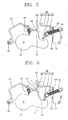
- the delay member 141 when the delay member 141 is pivoted by an external force, etc. in a direction so as for the first contact portion 145 to approach the switch 131, as shown in Fig. 6 , the pivoting movement of the delay member 141 is restricted as the rounded portion 149 contacts the bent end portion 125.
- the driving arm 117 and the delay member 141 contact each other, they are actually spaced apart from each other along the axial direction of the main shaft 115, thereby not contacting each other.
- the reset plate 121 In the state that the delay member 141 is pivoted via the dead point and contacts the bent end portion 125, when the main shaft 115 is rotated to a closing position, the reset plate 121 is rotated (in a clockwise direction in the drawing) by the elastic urging force of the reset plate spring 127. The bent end portion 125 of the reset plate 121 upwardly (in the drawing) presses upon the rounded portion 149 of the second contact portion 147 such that the delay member 141 is pivoted in a direction so as to separate the first contact portion 145 from the switch 131 so as to pass the dead point.
- the delay member 141 is pivoted in a direction to space the first contact portion 145 apart from the switch 131 by the elastic urging force of the delay member spring 151, and is then stopped from pivoting further by the stopper 133, thereby being separated from the switch 131.
- the bent end portion 125 having pivoted past the rounded portion 149 then presses upon the first contact portion 145, thereby pivoting the delay member 141 toward the switch 131.
- the delay member 141 passes the dead point of the delay member spring 151 while being pivoted, the delay member 141 then continues to pivot under the elastic urging force of the delay member spring 151.
- the first contact portion 145 contacts the detection portion 132 of the switch 131.
- the switch 131 outputs a signal to the outside when the first contact portion 145 contacts the detection portion 132.
- the reset plate operates the delay member, while being pivoted centering around the pivot shaft separate from the main shaft.
- the reset plate may be configured to contact the delay member with a certain time delay, while being pivoted centering around the main shaft.
- the present invention provides a time delay output apparatus for a circuit breaker, which can simplify its construction, reduce its size and lower its manufacturing cost by excluding the use of a large size mass.
- the present invention provides a time delay output apparatus for a circuit breaker which can prevent malfunction caused by reduced inertia of when a mass is vibrated or moved by electromagnetic repulsion force or external force, and can enhance operational reliability, by excluding the use of the mass.
- the contact end portion of the reset plate and the second contact portion of the delay member may interact with each other. Accordingly, the delay member is always pivoted in a direction to contact the switch at an initial position, and after contacting the contact, the switch may always output a signal after a certain preset time delay, thus to enhance the reliability of its operation.
Landscapes
- Driving Mechanisms And Operating Circuits Of Arc-Extinguishing High-Tension Switches (AREA)
- Arc-Extinguishing Devices That Are Switches (AREA)
- Keying Circuit Devices (AREA)
- Relay Circuits (AREA)
Claims (5)
- Zeitverzögerungsausgabevorrichtung für einen Schutzschalter, umfassend:einen Schalter (131), der an einer Seite einer Hauptwelle (115) rotierbar in Richtungen zum Öffnen/Schließen eines festen Schütz (111) und eines beweglichen Schütz (112) angeordnet ist;ein Verzögerungselement (141), das zwischen der Hauptwelle und dem Schalter angeordnet ist, um so den Schalter mit einer vorher eingestellten Zeitverzögerung zu bedienen;
gekennzeichnet durcheine Zurücksetzplatte (121), die angeordnet ist, um von dem Verzögerungselement getrennt zu sein, um eine Antriebskraft der Hauptwelle an das Verzögerungselement nach der Verzögerungszeit zu übertragen;eine Verzögerungselementfeder (151), die das Verzögerungselement in Kontakt mit dem Schalter treibt;einen Stopper (133) zum Beschränken einer Drehbewegung des Verzögerungselements in eine Richtung, um das Verzögerungselement von dem Schalter zu trennen,ein Antriebsarm (117) ist angeordnet um in eine radiale Richtung bei der Hauptwelle herauszuragen, um so die Zurücksetzplatte zu kontaktieren;eine Zurücksetzplattenfeder (127), die die Zurücksetzplatte in Kontakt mit dem Antriebsarm treibt;ein gebogener Endanteil (125), der gebogen ist, um das Verzögerungselement zu kontaktieren, ist bei der Zurücksetzplatte gebildet;wobei die Zurücksetzplatte rotierbar ist, zentriert um eine Drehgelenkswelle (123), die parallel zu der Hauptwelle angeordnet ist,
wobei das Verzögerungselement umfasst:eine zweite Drehgelenkswelle (143);einen ersten Kontaktanteil (145), der sich nach außen von einer Seite der zweiten Drehgelenkswelle erstreckt zum Kontaktieren des Schalters; undeinen zweiten Kontaktanteil (147), der sich nach außen von einer anderen Seite der zweiten Drehgelenkswelle erstreckt,wobei die Verzögerungselementfeder einen Todpunkt zwischen einer Schließposition und einer Öffnungsposition des Verzögerungselements aufweist,wobei, wenn die Hauptwelle zu einer Auslöseposition rotiert ist, die Zurücksetzplatte den zweiten Kontaktanteil drückt, wodurch das Verzögerungselement gedreht wird, und wenn die Hauptwelle in eine Richtung rotiert wird, um den festen Schütz und den bewegbaren Schütz miteinander zu kontaktieren, drückt die Zurücksetzplatte den ersten Kontaktanteil, wodurch das Verzögerungselement gedreht wird. - Vorrichtung nach Anspruch 1, wobei die Verzögerungselementfeder als eine aufgewickelte Spannungsfeder gebildet ist.
- Vorrichtung nach Anspruch 1, wobei das Verzögerungselement den Schalter bedient, nachdem der feste Schütz und der bewegliche Schütz einander kontaktieren.
- Vorrichtung nach Anspruch 1, wobei der gebogene Endanteil das Verzögerungselement kontaktiert und die Drehbewegung des Verzögerungselements beschränkt wenn das Verzögerungselement plötzlich rotiert wird.
- Vorrichtung nach Anspruch 4, wobei in dem Zustand, in dem der gebogene Endanteil und das Verzögerungselement einander kontaktieren, wenn die Hauptwelle rotiert wird, zu dem Zeitpunkt einer Schließhandlung, drückt der gebogene Endanteil den zweiten Kontaktanteil und die Zurücksetzplatte wird in eine Richtung gedreht, um das Verzögerungselement von dem Schalter zu trennen, und dann drückt die Zurücksetzplatte den ersten Kontaktanteil, wodurch der erste Kontaktanteil den Schalter kontaktiert.
Applications Claiming Priority (1)
| Application Number | Priority Date | Filing Date | Title |
|---|---|---|---|
| KR1020070070278A KR100876412B1 (ko) | 2007-07-12 | 2007-07-12 | 차단기의 지연시간 출력장치 |
Publications (3)
| Publication Number | Publication Date |
|---|---|
| EP2015340A2 EP2015340A2 (de) | 2009-01-14 |
| EP2015340A3 EP2015340A3 (de) | 2010-03-31 |
| EP2015340B1 true EP2015340B1 (de) | 2015-06-17 |
Family
ID=39764864
Family Applications (1)
| Application Number | Title | Priority Date | Filing Date |
|---|---|---|---|
| EP08011710.4A Active EP2015340B1 (de) | 2007-07-12 | 2008-06-27 | Verzögerungsausgabegerät für einen Schutzschalter |
Country Status (8)
| Country | Link |
|---|---|
| US (1) | US8053695B2 (de) |
| EP (1) | EP2015340B1 (de) |
| JP (1) | JP4750829B2 (de) |
| KR (1) | KR100876412B1 (de) |
| CN (1) | CN101345168B (de) |
| ES (1) | ES2547012T3 (de) |
| MY (1) | MY157960A (de) |
| RU (1) | RU2390867C2 (de) |
Cited By (1)
| Publication number | Priority date | Publication date | Assignee | Title |
|---|---|---|---|---|
| US11872837B2 (en) | 2019-01-22 | 2024-01-16 | Flooring Technologies Ltd. | Abrasion-resistant wood board |
Families Citing this family (8)
| Publication number | Priority date | Publication date | Assignee | Title |
|---|---|---|---|---|
| CN101552160B (zh) * | 2008-03-31 | 2012-01-11 | 北京人民电器厂有限公司 | 具有延时控制装置的电路保护开关 |
| KR100996791B1 (ko) * | 2008-04-10 | 2010-11-25 | 엘에스산전 주식회사 | 진공차단기의 주회로 단자 어셈블리 |
| DE102009035889B4 (de) * | 2009-08-03 | 2011-11-10 | Abb Technology Ag | Federspeicherantrieb mit Verzögerungsschaltung |
| WO2015081843A1 (zh) * | 2013-12-05 | 2015-06-11 | 德力西电气有限公司 | 接触板固定结构 |
| KR101759601B1 (ko) * | 2015-12-28 | 2017-07-31 | 엘에스산전 주식회사 | 기중 차단기용 지연시간 발생장치 |
| KR101869724B1 (ko) * | 2017-01-05 | 2018-06-21 | 엘에스산전 주식회사 | 회로차단기의 전자 트립 장치 |
| KR102299858B1 (ko) | 2017-03-15 | 2021-09-08 | 엘에스일렉트릭 (주) | 회로차단기의 전자 트립 장치 |
| FR3114435A1 (fr) * | 2020-09-18 | 2022-03-25 | Schneider Electric Industries Sas | Dispositif pour le contrôle d’un microcontact dans un appareil de connexion électrique |
Family Cites Families (24)
| Publication number | Priority date | Publication date | Assignee | Title |
|---|---|---|---|---|
| SU531214A1 (ru) | 1974-01-22 | 1976-10-05 | Предприятие П/Я А-7147 | Автоматический выключатель |
| SU752548A1 (ru) | 1978-04-10 | 1980-07-30 | За витель | Селективный токоограничивающий автоматический выключатель |
| JPS56120625A (en) | 1980-02-04 | 1981-09-22 | Tetsuo Ito | Method and apparatus for liquefaction and recovery of polychlorinated biphenyl gas |
| SU907629A1 (ru) | 1980-06-25 | 1982-02-23 | За витель | Селективно-токоограничивающий автоматический выключатель |
| GB8300662D0 (en) | 1983-01-11 | 1983-02-09 | Coal Industry Patents Ltd | Catalyst production |
| US4639561A (en) * | 1984-12-18 | 1987-01-27 | Square D Company | Mechanical time delay mechanism |
| US5089797A (en) | 1990-11-14 | 1992-02-18 | Westinghouse Electric Corp. | Circuit breaker with dual function electromagnetic tripping mechanism |
| JP3780537B2 (ja) | 1994-09-22 | 2006-05-31 | 株式会社安川電機 | 遮断器の操作装置 |
| RU2074438C1 (ru) | 1994-10-14 | 1997-02-27 | Всероссийский электротехнический институт им.В.И.Ленина | Электромагнитный привод выключателей |
| FR2744563B1 (fr) * | 1996-02-06 | 1998-04-03 | Schneider Electric Sa | Mecanisme de commande d'un disjoncteur a verrou debrayable sur un court-circuit |
| JPH09320421A (ja) | 1996-05-30 | 1997-12-12 | Hochiki Corp | 遅延型圧力スイッチ装置 |
| AT405113B (de) * | 1996-06-14 | 1999-05-25 | Felten & Guilleaume Ag Oester | Auslöse-einrichtung für ein überstrom-abschaltgerät |
| FR2777696B1 (fr) | 1998-04-17 | 2000-05-26 | Schneider Electric Ind Sa | Dispositif de commande de la decharge et du debrayage d'un accumulateur d'energie lors de l'extraction d'un disjoncteur debrochable |
| KR100497961B1 (ko) | 2003-07-09 | 2005-07-01 | 탱크테크 (주) | 선박 예인장치 |
| US6864450B1 (en) * | 2004-05-19 | 2005-03-08 | Eaton Corporation | Circuit breaker with delay mechanism |
| US20080122563A1 (en) * | 2006-08-28 | 2008-05-29 | Ls Industrial Systems Co., Ltd. | Instantaneous trip mechanism for mould cased circuit breaker |
| KR100771918B1 (ko) * | 2006-10-17 | 2007-11-01 | 엘에스산전 주식회사 | 기중차단기의 개폐기구 |
| KR100771922B1 (ko) * | 2006-10-17 | 2007-11-01 | 엘에스산전 주식회사 | 기중 차단기 |
| KR100817118B1 (ko) * | 2006-10-17 | 2008-03-27 | 엘에스산전 주식회사 | 기중차단기의 가동접촉자 |
| KR100789448B1 (ko) * | 2006-12-29 | 2007-12-28 | 엘에스산전 주식회사 | 배선용 차단기용 단자 모듈 조립체 및 상기 단자 모듈조립체를 장착한 배선용 차단기 |
| KR100854384B1 (ko) * | 2007-03-08 | 2008-08-26 | 엘에스산전 주식회사 | 기중 차단기의 투입 스프링 자동 방세 장치 및 투입 스프링자동 방세 장치를 갖는 기중 차단기 |
| KR100890754B1 (ko) * | 2007-07-12 | 2009-03-26 | 엘에스산전 주식회사 | 기중 차단기용 투입작동 가능 표시장치 및 이를 갖는 기중차단기 |
| KR100876408B1 (ko) * | 2007-07-12 | 2008-12-31 | 엘에스산전 주식회사 | 기계적 트립 표시 기구를 갖는 기중 차단기 |
| KR100882399B1 (ko) * | 2007-08-20 | 2009-02-05 | 엘에스산전 주식회사 | 자동 풀림 링크 기구를 구비한 회로 차단기 및 이에사용되는 자동풀림 링크 기구 |
-
2007
- 2007-07-12 KR KR1020070070278A patent/KR100876412B1/ko active IP Right Grant
-
2008
- 2008-06-27 US US12/163,002 patent/US8053695B2/en active Active
- 2008-06-27 EP EP08011710.4A patent/EP2015340B1/de active Active
- 2008-06-27 ES ES08011710.4T patent/ES2547012T3/es active Active
- 2008-07-08 MY MYPI20082518A patent/MY157960A/en unknown
- 2008-07-10 JP JP2008180253A patent/JP4750829B2/ja active Active
- 2008-07-11 RU RU2008128387/09A patent/RU2390867C2/ru active
- 2008-07-11 CN CN2008101335276A patent/CN101345168B/zh active Active
Cited By (1)
| Publication number | Priority date | Publication date | Assignee | Title |
|---|---|---|---|---|
| US11872837B2 (en) | 2019-01-22 | 2024-01-16 | Flooring Technologies Ltd. | Abrasion-resistant wood board |
Also Published As
| Publication number | Publication date |
|---|---|
| RU2390867C2 (ru) | 2010-05-27 |
| ES2547012T3 (es) | 2015-09-30 |
| US8053695B2 (en) | 2011-11-08 |
| JP4750829B2 (ja) | 2011-08-17 |
| RU2008128387A (ru) | 2010-01-20 |
| KR100876412B1 (ko) | 2008-12-31 |
| CN101345168A (zh) | 2009-01-14 |
| EP2015340A2 (de) | 2009-01-14 |
| JP2009021248A (ja) | 2009-01-29 |
| MY157960A (en) | 2016-08-30 |
| US20090014301A1 (en) | 2009-01-15 |
| EP2015340A3 (de) | 2010-03-31 |
| CN101345168B (zh) | 2011-04-20 |
Similar Documents
| Publication | Publication Date | Title |
|---|---|---|
| EP2015340B1 (de) | Verzögerungsausgabegerät für einen Schutzschalter | |
| JP5426516B2 (ja) | 瞬時トリップメカニズムを有する配線用遮断器 | |
| JP4866400B2 (ja) | 自動解除リンク機構を備えた回路遮断器 | |
| EP1812943B1 (de) | Selbstschalter mit durch bewegtkontakt aktivierte auslösevorrichtung | |
| US20100044196A1 (en) | Circuit breaker, in particular for low voltages | |
| US9208962B2 (en) | Circuit breaker including an anti-rebound system, anti-rebound system for a circuit breaker and method | |
| EP2549499B1 (de) | Elektrisches Schaltgerät und Sekundärauslösungsmechanismus dafür | |
| KR100996806B1 (ko) | 모터 보호용 차단기의 개폐기구 | |
| US10497526B2 (en) | Molded-case circuit breaker with main contact interlock feature | |
| EP3104385B1 (de) | Haltevorrichtung für ein schutzschalterkontaktsystem | |
| KR101093850B1 (ko) | 회로차단기 | |
| JP5418024B2 (ja) | 回路遮断器 | |
| JP4906881B2 (ja) | 熱動形過負荷継電器 | |
| KR100909425B1 (ko) | 트립 위치 지시 기구를 가진 배선용 차단기 | |
| KR200441576Y1 (ko) | 배선용 차단기의 개폐장치 | |
| EP3319102B1 (de) | Anzeigevorrichtung eines elektrischen schalters | |
| EP2681754B1 (de) | Verbesserter betätigungsmechanismus für einen schutzschalter | |
| WO2008049336A1 (fr) | Disjoncteur destiné à couper rapidement un circuit à basse tension | |
| KR200398419Y1 (ko) | 진공 차단기의 다절 링크식 작동기구 | |
| US11062858B2 (en) | Electrical switching unit with separable contacts | |
| KR101830668B1 (ko) | 배선용 차단기 | |
| KR101076288B1 (ko) | 급속반전 기구가 구비된 배선용 차단기 | |
| EP3048631B1 (de) | Verfahren zum Betrieb eines Schutzschalters und Schutzschalter | |
| CN105719921B (zh) | 用于低压断路器的热脱扣装置以及包括这种装置的断路器 | |
| JPH0428136A (ja) | 回路遮断器 |
Legal Events
| Date | Code | Title | Description |
|---|---|---|---|
| PUAI | Public reference made under article 153(3) epc to a published international application that has entered the european phase |
Free format text: ORIGINAL CODE: 0009012 |
|
| 17P | Request for examination filed |
Effective date: 20080627 |
|
| AK | Designated contracting states |
Kind code of ref document: A2 Designated state(s): AT BE BG CH CY CZ DE DK EE ES FI FR GB GR HR HU IE IS IT LI LT LU LV MC MT NL NO PL PT RO SE SI SK TR |
|
| AX | Request for extension of the european patent |
Extension state: AL BA MK RS |
|
| PUAL | Search report despatched |
Free format text: ORIGINAL CODE: 0009013 |
|
| AK | Designated contracting states |
Kind code of ref document: A3 Designated state(s): AT BE BG CH CY CZ DE DK EE ES FI FR GB GR HR HU IE IS IT LI LT LU LV MC MT NL NO PL PT RO SE SI SK TR |
|
| AX | Request for extension of the european patent |
Extension state: AL BA MK RS |
|
| 17Q | First examination report despatched |
Effective date: 20100713 |
|
| AKX | Designation fees paid |
Designated state(s): DE ES FR GB IT |
|
| GRAP | Despatch of communication of intention to grant a patent |
Free format text: ORIGINAL CODE: EPIDOSNIGR1 |
|
| INTG | Intention to grant announced |
Effective date: 20150105 |
|
| GRAS | Grant fee paid |
Free format text: ORIGINAL CODE: EPIDOSNIGR3 |
|
| GRAA | (expected) grant |
Free format text: ORIGINAL CODE: 0009210 |
|
| AK | Designated contracting states |
Kind code of ref document: B1 Designated state(s): DE ES FR GB IT |
|
| REG | Reference to a national code |
Ref country code: GB Ref legal event code: FG4D |
|
| REG | Reference to a national code |
Ref country code: DE Ref legal event code: R096 Ref document number: 602008038563 Country of ref document: DE |
|
| REG | Reference to a national code |
Ref country code: ES Ref legal event code: FG2A Ref document number: 2547012 Country of ref document: ES Kind code of ref document: T3 Effective date: 20150930 |
|
| REG | Reference to a national code |
Ref country code: FR Ref legal event code: PLFP Year of fee payment: 9 |
|
| REG | Reference to a national code |
Ref country code: DE Ref legal event code: R097 Ref document number: 602008038563 Country of ref document: DE |
|
| PLBE | No opposition filed within time limit |
Free format text: ORIGINAL CODE: 0009261 |
|
| STAA | Information on the status of an ep patent application or granted ep patent |
Free format text: STATUS: NO OPPOSITION FILED WITHIN TIME LIMIT |
|
| 26N | No opposition filed |
Effective date: 20160318 |
|
| REG | Reference to a national code |
Ref country code: FR Ref legal event code: PLFP Year of fee payment: 10 |
|
| REG | Reference to a national code |
Ref country code: FR Ref legal event code: PLFP Year of fee payment: 11 |
|
| PGFP | Annual fee paid to national office [announced via postgrant information from national office to epo] |
Ref country code: GB Payment date: 20200408 Year of fee payment: 13 |
|
| GBPC | Gb: european patent ceased through non-payment of renewal fee |
Effective date: 20210627 |
|
| PG25 | Lapsed in a contracting state [announced via postgrant information from national office to epo] |
Ref country code: GB Free format text: LAPSE BECAUSE OF NON-PAYMENT OF DUE FEES Effective date: 20210627 |
|
| PGFP | Annual fee paid to national office [announced via postgrant information from national office to epo] |
Ref country code: FR Payment date: 20230306 Year of fee payment: 16 |
|
| PGFP | Annual fee paid to national office [announced via postgrant information from national office to epo] |
Ref country code: IT Payment date: 20230309 Year of fee payment: 16 |
|
| PGFP | Annual fee paid to national office [announced via postgrant information from national office to epo] |
Ref country code: DE Payment date: 20230306 Year of fee payment: 16 |
|
| P01 | Opt-out of the competence of the unified patent court (upc) registered |
Effective date: 20230625 |
|
| PGFP | Annual fee paid to national office [announced via postgrant information from national office to epo] |
Ref country code: ES Payment date: 20230714 Year of fee payment: 16 |