EP2014368A1 - Pipettenschwenkvorrichtung - Google Patents
Pipettenschwenkvorrichtung Download PDFInfo
- Publication number
- EP2014368A1 EP2014368A1 EP07117443A EP07117443A EP2014368A1 EP 2014368 A1 EP2014368 A1 EP 2014368A1 EP 07117443 A EP07117443 A EP 07117443A EP 07117443 A EP07117443 A EP 07117443A EP 2014368 A1 EP2014368 A1 EP 2014368A1
- Authority
- EP
- European Patent Office
- Prior art keywords
- housing
- pipette
- pivot
- holder
- pipette holder
- Prior art date
- Legal status (The legal status is an assumption and is not a legal conclusion. Google has not performed a legal analysis and makes no representation as to the accuracy of the status listed.)
- Withdrawn
Links
- 230000008878 coupling Effects 0.000 claims abstract description 7
- 238000010168 coupling process Methods 0.000 claims abstract description 7
- 238000005859 coupling reaction Methods 0.000 claims abstract description 7
- 230000000717 retained effect Effects 0.000 claims description 2
- 208000012514 Cumulative Trauma disease Diseases 0.000 description 6
- 230000000284 resting effect Effects 0.000 description 5
- 230000003252 repetitive effect Effects 0.000 description 3
- 230000000712 assembly Effects 0.000 description 2
- 238000000429 assembly Methods 0.000 description 2
- 239000007788 liquid Substances 0.000 description 2
- 239000000463 material Substances 0.000 description 2
- 206010033372 Pain and discomfort Diseases 0.000 description 1
- 208000021945 Tendon injury Diseases 0.000 description 1
- 208000003295 carpal tunnel syndrome Diseases 0.000 description 1
- 238000004140 cleaning Methods 0.000 description 1
- 238000013461 design Methods 0.000 description 1
- 238000011161 development Methods 0.000 description 1
- 230000018109 developmental process Effects 0.000 description 1
- 208000037265 diseases, disorders, signs and symptoms Diseases 0.000 description 1
- 208000035475 disorder Diseases 0.000 description 1
- 239000000945 filler Substances 0.000 description 1
- 239000012530 fluid Substances 0.000 description 1
- 239000003517 fume Substances 0.000 description 1
- 239000011521 glass Substances 0.000 description 1
- 238000000034 method Methods 0.000 description 1
- 238000012545 processing Methods 0.000 description 1
- 230000002441 reversible effect Effects 0.000 description 1
- 238000012549 training Methods 0.000 description 1
Images


Classifications
-
- B—PERFORMING OPERATIONS; TRANSPORTING
- B01—PHYSICAL OR CHEMICAL PROCESSES OR APPARATUS IN GENERAL
- B01L—CHEMICAL OR PHYSICAL LABORATORY APPARATUS FOR GENERAL USE
- B01L3/00—Containers or dishes for laboratory use, e.g. laboratory glassware; Droppers
- B01L3/02—Burettes; Pipettes
- B01L3/021—Pipettes, i.e. with only one conduit for withdrawing and redistributing liquids
- B01L3/0217—Pipettes, i.e. with only one conduit for withdrawing and redistributing liquids of the plunger pump type
-
- B—PERFORMING OPERATIONS; TRANSPORTING
- B01—PHYSICAL OR CHEMICAL PROCESSES OR APPARATUS IN GENERAL
- B01L—CHEMICAL OR PHYSICAL LABORATORY APPARATUS FOR GENERAL USE
- B01L3/00—Containers or dishes for laboratory use, e.g. laboratory glassware; Droppers
- B01L3/02—Burettes; Pipettes
- B01L3/021—Pipettes, i.e. with only one conduit for withdrawing and redistributing liquids
- B01L3/0213—Accessories for glass pipettes; Gun-type pipettes, e.g. safety devices, pumps
-
- B—PERFORMING OPERATIONS; TRANSPORTING
- B01—PHYSICAL OR CHEMICAL PROCESSES OR APPARATUS IN GENERAL
- B01L—CHEMICAL OR PHYSICAL LABORATORY APPARATUS FOR GENERAL USE
- B01L2200/00—Solutions for specific problems relating to chemical or physical laboratory apparatus
- B01L2200/02—Adapting objects or devices to another
- B01L2200/025—Align devices or objects to ensure defined positions relative to each other
-
- B—PERFORMING OPERATIONS; TRANSPORTING
- B01—PHYSICAL OR CHEMICAL PROCESSES OR APPARATUS IN GENERAL
- B01L—CHEMICAL OR PHYSICAL LABORATORY APPARATUS FOR GENERAL USE
- B01L2200/00—Solutions for specific problems relating to chemical or physical laboratory apparatus
- B01L2200/08—Ergonomic or safety aspects of handling devices
- B01L2200/087—Ergonomic aspects
Definitions
- the present invention relates to a laboratory device, and in particular, to an adjustable pipette device for aspirating and dispensing liquids.
- Pipetting is the act of aspirating and dispensing controlled volumes of liquid, and is one of the most frequently performed repetitive lab operations. Attempts to minimize the occurrences of RSIs in the lab have focused on training technicians in body mechanics (e.g., posture, pipetting technique, etc.), and providing an ergonomic pipette device.
- a pipette device is as important as the manner in which it is used.
- Pipette manufacturers recognize the benefits of an ergonomic pipette dev ice, as is evidenced by the number of different ergonomic devices available.
- many devices include a contoured handgrip to allow for a relaxed hold on the device.
- a contoured handgrip is not sufficient to completely obviate the devel opment of an RSI or CTD in awkward, confined or restricted spaces, such as pipetting at lowered benchtops or in fume hoods where arm, joint or tendon strain may occur. Healthy technicians will not only have better attendance and attitude, but will also perform better with improved pipetting accuracy and precision. Therefore, in view of the foregoing, a need exists for an adjustab le ergonomic pipette device.
- the invention provides a pipette holder for retaining a pipette at a plurality of angles relative to the holder.
- the pipette holder includes a first housing portion, a second housing portion supporting the pipette, and a pivot mechanism pivotally coupling the first housing portion and the second housing portion.
- the pipette holder in another embodiment, includes a housing including a first portion and a second portion and a nozzle assembly for accepting a pipette, the nozzle assembly coupled to the second portion of the housing.
- the pipette holder also inc ludes a pivot mechanism for coupling the first portion of the housing and the second portion of the housing to permit the second portion to pivot relative to the first portion.
- the pipette holder includes a housing including a first portion and a second portion pivotally coupled together and a pipette retaining member located on the second portion of the housing.
- the pipette holder also includes an indexing system on te housing for adjusting a pivot angle of the second portion relative to the first portion.
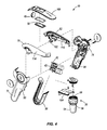
- the pip ette device 10 includes a generally pistol-shaped housing 14, although other shapes are suitable for the housing 14.
- the housing 14 may be constructed of any suitable material known in the art; however, in the illustrated embodiment, the housing 14 is constructed of a plastic material molded or otherwise formed into four pieces that are secured together.
- the housing 14 includes an external matte finish that provides a non -slip surface for improved gripping and handling of the pipette de vice 10.
- the housing 14 includes a handgrip portion 18, a barrel portion 22, and a nozzle assembly 26.
- the handgrip portion 18 and the barrel portion 22 are each formed from a pair of opposed housings coupled together.
- such pipette devices may be referred to as pipette fillers (electronic), pipetting aids or pipette guns.
- the barrel portion 22 is oriented substantially parallel with a horizontal work surface (e.g., table, benchtop, etc.). In this way, a device axis 34 ( Fig. 2 ) is defined through the pipette device 10, which is generally horizontal during typical use, but may be oriented otherwise for a user's comfort.
- the nozzle assembly 26 is operable to releasably retain glass and pl astic pipettes 36 of various sizes and volumes. Additionally, as discussed in further detail below, the barrel portion 22 may be pivoted relative to the handgrip portion 18 (e.g., towards and away from the horizontal work surface or transverse to the device axis 34) to reduce arm strain during pipetting.
- the handgrip portion 18 includes an ergonomic treatment to reduce hand strain and is hand-neutral (i.e., usable by both right -handed and left-handed users).
- Trigger buttons 38A, 38B project through a portion of the handgrip portion 18.
- the buttons 38A, 38B are positioned for actuation by a user's fingers and may include an ergonomic treatment, such as a curved, concave, or contoured end surface, for reducing finger fatigue.
- each button 38A, 38B may include a button-identifying portion such as an indent or protrusion that provides a user with a tactile means for telling the buttons 38A, 38B apart.
- the buttons 38A, 38B activate the device to aspirate and dispense fluid, respectively.
- the buttons 38A, 38B actuate microswitches or the like on a circuit board to operate a reversible motorized pump mechanism (not shown), such as a vacuum pump or the like.
- the pump mechanism applies a positive or negative pressure to an attached pipette 36 via one of the variable valve assemblies 42 and connective flexible tubing (not shown) within the housing 14.
- a continuous speed dial 46 accessible from the barrel portion 22 is linked to the circuit board to select the speed of the pump mechanism depending on the user's desired pipetting speed and precision. Additionally, the pump mechanism is energized by one or more batteries (not shown), which are rechargeably linked to a power jack.
- An LCD screen 50 in the barrel portion 22, and positioned proximate the speed dial 46, provides an indication of the speed setting and the battery charge of the pipette device 10 .
- the nozzle assembly 26 is rigidly held by and located at one end of the barrel portion 22 opposite the handgrip portion 18.
- the nozzle assembly 26 includes a nozzle housing 54 having a generally frustoconcical shape and a central bore 56 therethrough.
- the exterior of the nozzle 54 may include gripping detents 58 that facilitate disassembly of the nozzle assembly 26 for filter replacement, cleaning, autoclaving, or the like.
- the nozzle assembly 26 includes a number of elements engaged within the nozzle housing 54 to provide a continuous positive or negative pressure path between the attached pipette 36 and the pump mechanism. It should be readily apparent to those of skill in the art that other known nozzle assemblies may be used with the pipette device.
- the pipette device 10 includes a pivot mechanism 62, about a pivot axis 66 ( Fig.2 ), or pivot point, to selectively pivot the barrel portion 22 relative to the handgrip portion 18 to reduce arm strain during pipetting.
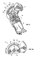
- the housing 14 of the pipette device 10 is formed from a first handgrip housing 70, a second handgrip housing 74, a first barrel housing 78, and a second barrel housing 82.
- the first and second handgrip housings 70, 74 are of substantially similar size and shape, and are coupled together with an intermediate housing 86 to define the handgrip portion 18.
- Each of the handgrip housings 70, 74 includes an outer surface 90 and an inner surface 94.
- a pivot boss 98 extends outwardly from the inner surface 94 of each handgrip housing 70, 74 to define the pivot axis 66 of the pipette device e 10 .
- the pivot bosses 98 are sized and shaped to snugly fit within pivot sleeves 102 on the barrel housings 78, 82.
- the inner surface 94 of each handgrip housing 70, 74 also includes a number of bosses, sleeves, extensions and recesses to mate with structure on the opposed handgrip housing 74, 70.
- the first and second barrel housings 78, 82 are of substantially similar size and shape, and are coupled together with an upper housing 100 and a lower housing 104 to define the barrel portion 22.
- First ends 106 of the barrel housings 78, 82 support the nozzle assembly 26, and second ends 110 of the barrel housings 78, 82 fit within a first end of the handle portion 18 for pivotally coupling the barrel portion 22 to the handle portion 18.
- Each barrel housing 78, 82 includes an outer surface 114 and an inner surface 118 .
- a pivot sleeve 102 extends from the inner surface 118 of each barrel housing 78, 82 to further define the pivot axis 66 of the pipette device 10.
- the pivot sleeves 102 are sized and shaped to snugly receive the pivot bosses 98 of the handgrip housings 70, 74.
- the inner surface 118 of each barrel housing 78, 82 also includes a number of bosses, sleeves, extensions and recesses to mate with structure on the opposed barrel housing 82, 78.
- the pivot bosses 98 and the pivot sleeves 102 define the pivot axis 66 about which the barrel portion 22 pivots transverse to the device axis 34 ( Fig. 2 ).
- the pivot bosses 98 and pivot sleeves 102 may be cylindrically, frustoconically, or otherwise shaped to permit rotation.
- the bosses 98 of the handgrip housings 70, 74 include projecting extensions 126 ( Figs. 5-6 ) to provide a more tolerant fit in the sleeves 102.
- the sleeves 102 and the bosses 98 are rotatably engaged to adjustably pivot the barrel portion 22 about the pivot axis 66 and to change its angular position to the handgrip portion 18 .
- the pipette device 10 may alternatively include, for example, a swivel, ball, joint, articulation, ball-in-socket, or other like means for providing angular adjustability in a variety of directions.
- the pipette device 10 may include a locking means to lock, clamp, or otherwise inhibit adjustment of the swivel, ball, joint, articulation, b all-in-socket, or the like to retain the barrel portion 22 in a desired position.
- the locking means may include, for example, a pin, screw, clamp, vise, or other fastening means known in the art.
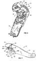
- the barrel portion 22 is pivotab le throughout a range of approximately 20° relative to the device axis 34 , with five discrete resting positions spaced approximately 5° apart.
- the pivoting mechanism 62 of the pipette device 10 includes an indexing system 130 to hold the barrel portion 22 in one of the discrete positions relative to the handgrip portion 18 .
- the indexing system 130 includes indexing posts 134A, 134B positioned on the inner surfaces 94 of the handgrip housings 70, 74 and an indexing surface 138 positioned on the outer surfaces 114 of the barrel housings 78, 82.
- the posts 134A, 134B engage the surface 138 to hold the barrel portion 22 in a desired position.
- each handgrip housing 70, 74 includes a pair of indexing posts 134A, 134B ( Fig. 5A ) extending toward the opposed barrel housing 78, 82.
- the indexing posts 134A, 134B are positioned radially outward from the pivot boss 98, i.e., the pivot axis 66, along an upper edge 142 of the handgrip housing 70, 74.
- Fig. 5A shows an enlarged view of the upper edge 142 of the first handgrip housing 70
- the upper edge 142 of the second handgrip housing 74 is generally a mirror image of the first handgrip housing 70.
- two indexing posts are shown; however, i t should be readily apparent to those of skill in the art that in further embodiments fewer or more posts may be used.
- each barrel housing 78, 82 includes the indexing surface 138 ( Fig 7A ), which is recessed with respect to the outer surface 114.
- the indexing surface 138 is generally arc-shaped and positioned radially outward from and centered about the pivot sleeve 102, i.e., the pivot point 66.
- the indexing surface 138 includes a plurality of ridges 146 spaced apart to define indents 150 between adjacent ridges. Each indent 150 corresponds to a resting position for the opposed indexing post 134A, 134B.
- the indexing surface 138 includes two groups 146A, 146B of six ridges each such that each group 146A, 146B defines five indents 150, i.e., resting positions.
- Each indexing post 134A, 134B operates in conjunction with one group 146A, 146B of ridges.
- Fig. 7A shows an enlarge d view of the indexing surface 138 of the first barrel housing 78
- Fig. 8 the indexing surface 138 of the second barrel housing 82 is generally a mirror image of the first barrel housing 78.
- ridges and indents may be formed in the indexing surface 138 and that a single group of ridges or multiple groups of ridges may be used to form the indexing system 130.
- the indexing posts 134A, 134B of the first handgrip housing 70 mate with the indexing surface 138 of the first barrel housing 78
- the indexing posts 134A, 134B of the second handgrip housing 74 mate with the indexing surface 138 of the second barrel housing 82.
- the ridges 146 associated with the first ridge group 146A of each barrel housing 78, 82 slide over the first indexing post 134A of the respective handgrip housing 70, 74
- an d the ridges 146 associated with the second ridge group 146B of each barrel housing 78, 82 slide over the second indexing post 134B of the respective handgrip housing 78, 82.
- the indexing system 130 operates similarly to a ratchet and pawl as the barrel portion 22 is pivoted between resting positions. It should be readily apparent to those of skill in the art that in further embodiments, the barrel portion 22 may have a larger or smaller pivot rang e and may include fewer or more resting positions. In a further embodiment, the indexing posts may be located on the barrel portion 22 and the indexing surface may be located on the handgrip portion 18.
- the indexing posts 134A, 134B are retained within the opposed indent s 150 at an endmost position 150A of the opposed ridge group 146A, 146B.
- a user holding the handgrip portion 18 places sufficient pressure on the barrel portion 22 to overcome the frictional engagement, disengage the indexing posts 134A, 134B from the associated inde nts 150 and rotate the barrel portion 22 relative to the handgrip portion 18.
- the ridges 146 slide over the indexing posts 134A, 134B of the associated handgrip housing 70, 74 until the barrel portion 22 reaches a desired angular position relative to the handgrip portion. Once the barrel portion 22 reaches the desired position, the indexing posts 134A, 134B frictionally engage the associated indents 150 to hold the barrel portion 22 in position.
Landscapes
- Health & Medical Sciences (AREA)
- Clinical Laboratory Science (AREA)
- Chemical & Material Sciences (AREA)
- Chemical Kinetics & Catalysis (AREA)
- Apparatus Associated With Microorganisms And Enzymes (AREA)
Applications Claiming Priority (1)
| Application Number | Priority Date | Filing Date | Title |
|---|---|---|---|
| US11/772,943 US20090007701A1 (en) | 2007-07-03 | 2007-07-03 | Pivoting pipette device |
Publications (1)
| Publication Number | Publication Date |
|---|---|
| EP2014368A1 true EP2014368A1 (de) | 2009-01-14 |
Family
ID=39720255
Family Applications (1)
| Application Number | Title | Priority Date | Filing Date |
|---|---|---|---|
| EP07117443A Withdrawn EP2014368A1 (de) | 2007-07-03 | 2007-09-27 | Pipettenschwenkvorrichtung |
Country Status (2)
| Country | Link |
|---|---|
| US (1) | US20090007701A1 (de) |
| EP (1) | EP2014368A1 (de) |
Families Citing this family (2)
| Publication number | Priority date | Publication date | Assignee | Title |
|---|---|---|---|---|
| USD772426S1 (en) | 2014-01-13 | 2016-11-22 | Gilson, Inc. | Pipette system cartridge |
| US20180096033A1 (en) * | 2016-10-04 | 2018-04-05 | International Business Machines Corporation | Query management in database management systems |
Citations (4)
| Publication number | Priority date | Publication date | Assignee | Title |
|---|---|---|---|---|
| US3004455A (en) * | 1960-11-08 | 1961-10-17 | Max C Bashore | Close quarter ratchet pipe wrench |
| US5002737A (en) * | 1985-07-08 | 1991-03-26 | Labsystems Oy | Electrically operated pipette |
| US20030074988A1 (en) * | 2001-07-06 | 2003-04-24 | Osmo Suovaniemi | Pipette device |
| EP1555067A2 (de) * | 2004-01-16 | 2005-07-20 | Heathrow Scientific LLC | Pipette mit schwenkbarem Pipettierkopf |
Family Cites Families (55)
| Publication number | Priority date | Publication date | Assignee | Title |
|---|---|---|---|---|
| US2517796A (en) * | 1945-11-28 | 1950-08-08 | Waddy T Mathis | Liquid-measuring dispenser |
| US2595493A (en) * | 1949-09-09 | 1952-05-06 | Ollie F Slaby | Liquid extracting apparatus |
| US3263554A (en) * | 1961-12-26 | 1966-08-02 | Beckman Instruments Inc | Cuvette with means for controlled volumetric displacement |
| US3418097A (en) * | 1965-08-30 | 1968-12-24 | Drummond Scient Co | Microhematocrit tube sealer |
| US3719087A (en) * | 1966-04-08 | 1973-03-06 | R Thiers | Pipetting apparatus and method |
| US3501964A (en) * | 1968-03-29 | 1970-03-24 | Drummond Instr Co | Assembly for injecting liquid samples into the chamber of a gas chromatography apparatus |
| US3656351A (en) * | 1970-06-25 | 1972-04-18 | Bio Data Corp | Pipette |
| US3847200A (en) * | 1972-05-01 | 1974-11-12 | Brinkmann Instr Inc | Apparatus for concentrating laboratory specimens by evaporation |
| US3834590A (en) * | 1972-10-24 | 1974-09-10 | Drummond Scient Co | Microliter fluid delivery apparatus |
| US3834240A (en) * | 1973-02-23 | 1974-09-10 | Drummond Scient Co | Apparatus for drawing liquids into, and expelling liquids from, a pipette or the like |
| DE2926691C2 (de) * | 1979-07-02 | 1983-05-26 | Eppendorf Gerätebau Netheler + Hinz GmbH, 2000 Hamburg | Repetierpipette |
| USD242729S (en) * | 1975-05-30 | 1976-12-14 | Drummond Scientific Company | Automatic pipette or the like |
| US3963061A (en) * | 1975-09-16 | 1976-06-15 | Drummond Scientific Company | Apparatus for drawing liquids into, and expelling liquids from a pipette |
| DE2549477C3 (de) * | 1975-11-05 | 1982-01-07 | Eppendorf Gerätebau Netheler + Hinz GmbH, 2000 Hamburg | Pipettiervorrichtung |
| US4063662A (en) * | 1976-07-08 | 1977-12-20 | Drummond Scientific Company | Calibrating means for a microdispenser |
| US4099548A (en) * | 1976-08-25 | 1978-07-11 | Oxford Laboratories Inc. | Hand-held pipette for repetitively dispensing precise volumes of liquid |
| US4219530A (en) * | 1978-01-27 | 1980-08-26 | Brinkmann Instruments, Inc. | Apparatus for analyzing biological specimens |
| DE2851532C2 (de) * | 1978-11-29 | 1981-02-19 | Boehringer Mannheim Gmbh, 6800 Mannheim | Pipette mit elastischem Balg |
| USD262319S (en) * | 1979-05-25 | 1981-12-15 | Drummond Scientific Company | Microdispenser |
| US4250755A (en) * | 1979-10-22 | 1981-02-17 | Drummond Scientific Co. | Pipette |
| DE3204178C2 (de) * | 1982-02-06 | 1986-03-20 | Eppendorf Gerätebau Netheler + Hinz GmbH, 2000 Hamburg | Pipettiervorrichtung |
| US4461328A (en) * | 1982-06-04 | 1984-07-24 | Drummond Scientific Company | Pipette device |
| USD277314S (en) * | 1982-09-30 | 1985-01-22 | Manostat Corporation | Hand-held pipetting device |
| US4659677A (en) * | 1983-05-26 | 1987-04-21 | Eastman Kodak Company | Method providing liquid mixing outside containers |
| US4527437A (en) * | 1983-07-06 | 1985-07-09 | Wescor, Inc. | Pipette controller |
| US4662545A (en) * | 1984-01-05 | 1987-05-05 | Drummond Scientific Company | Disposable capillary tube device |
| US4671123A (en) * | 1984-02-16 | 1987-06-09 | Rainin Instrument Co., Inc. | Methods and apparatus for pipetting and/or titrating liquids using a hand held self-contained automated pipette |
| US5187990A (en) * | 1984-02-16 | 1993-02-23 | Rainin Instrument Co., Inc. | Method for dispensing liquids with a pipette with compensation for air pressure and surface tension |
| DE3662650D1 (en) * | 1985-01-29 | 1989-05-11 | Fuji Photo Film Co Ltd | Duplex pipette |
| GB2174459B (en) * | 1985-05-04 | 1988-05-25 | Jencons | Liquid dispensing means |
| US4754771A (en) * | 1985-07-17 | 1988-07-05 | Hybritech Incorporated | Apparatus for washing beads |
| US5059398A (en) * | 1985-07-22 | 1991-10-22 | Drummond Scientific Company | Disposable preselected-volume capillary pipet device |
| US4624147A (en) * | 1985-11-12 | 1986-11-25 | Drummond Scientific Company | Pipet gun for drawing liquid into and expelling it from a pipet |
| USD299065S (en) * | 1986-03-05 | 1988-12-20 | Matrix Technologies Corporation | Pipettor |
| US4896270A (en) * | 1986-03-21 | 1990-01-23 | Matrix Technologies Corporation | Computer controlled pipetting system |
| JPS6347665A (ja) * | 1986-08-14 | 1988-02-29 | コントロン インスツルメンツ ホールディング エヌ.ブイ. | ピペット操作方法および装置 |
| US4831470A (en) * | 1987-10-13 | 1989-05-16 | Brand Technologies | Method and apparatus for recording disk servo information with detachable position decoder |
| US4967606A (en) * | 1988-04-29 | 1990-11-06 | Caveo Scientific Instruments, Inc. | Method and apparatus for pipetting liquids |
| US4910617A (en) * | 1988-04-29 | 1990-03-20 | Brand Technologies | Disk drive head positioning servo system utilizing encoded track zone information |
| DE3875117D1 (de) * | 1988-10-21 | 1992-11-05 | Eppendorf Geraetebau Netheler | Pipettiervorrichtung. |
| US4988481A (en) * | 1989-01-30 | 1991-01-29 | Labsystems Oy | Electrical pipette |
| US5043106A (en) * | 1989-02-15 | 1991-08-27 | Drummond Scientific Company | Method of casting optical mirrors |
| US5173266A (en) * | 1989-07-19 | 1992-12-22 | Drummond Scientific Company | Safety pipet |
| US5104625A (en) * | 1989-10-04 | 1992-04-14 | Drummond Scientific Company | Pipetter device |
| US5090255A (en) * | 1990-03-27 | 1992-02-25 | Drummond Scientific Company | Programmable pipet apparatus |
| DE4014333A1 (de) * | 1990-05-04 | 1991-11-28 | Eppendorf Geraetebau Netheler | Pipettiervorrichtung |
| DE4141608C2 (de) * | 1991-12-17 | 1993-12-02 | Eppendorf Geraetebau Netheler | Pipettiervorrichtung |
| US5214968A (en) * | 1992-01-06 | 1993-06-01 | Drummond Scientific Company | Pipet filling and discharge device |
| US5294405A (en) * | 1992-04-09 | 1994-03-15 | Drummond Scientific Company | Adjustable valve for pipette gun |
| FI921647A0 (fi) * | 1992-04-13 | 1992-04-13 | Labsystems Oy | Spetsdelpipett. |
| US5226572A (en) * | 1992-06-11 | 1993-07-13 | Comar, Inc. | Bulb actuator for dropper closure |
| FI922939A0 (fi) * | 1992-06-24 | 1992-06-24 | Labsystems Oy | Knappipett. |
| US5509318A (en) * | 1993-10-13 | 1996-04-23 | Manostat Corporation | Memory Mopet |
| DE4335863C1 (de) * | 1993-10-21 | 1995-02-02 | Eppendorf Geraetebau Netheler | Kolbenhubpipette |
| DE19748331C1 (de) * | 1997-10-31 | 1999-01-28 | Primed Medizintechnik Gmbh | Vorrichtung zur Aufnahme und Abgabe von Speichel |
-
2007
- 2007-07-03 US US11/772,943 patent/US20090007701A1/en not_active Abandoned
- 2007-09-27 EP EP07117443A patent/EP2014368A1/de not_active Withdrawn
Patent Citations (4)
| Publication number | Priority date | Publication date | Assignee | Title |
|---|---|---|---|---|
| US3004455A (en) * | 1960-11-08 | 1961-10-17 | Max C Bashore | Close quarter ratchet pipe wrench |
| US5002737A (en) * | 1985-07-08 | 1991-03-26 | Labsystems Oy | Electrically operated pipette |
| US20030074988A1 (en) * | 2001-07-06 | 2003-04-24 | Osmo Suovaniemi | Pipette device |
| EP1555067A2 (de) * | 2004-01-16 | 2005-07-20 | Heathrow Scientific LLC | Pipette mit schwenkbarem Pipettierkopf |
Also Published As
| Publication number | Publication date |
|---|---|
| US20090007701A1 (en) | 2009-01-08 |
Similar Documents
| Publication | Publication Date | Title |
|---|---|---|
| JP5192112B2 (ja) | 手持ちピペット | |
| US6486868B1 (en) | Two-handed input control apparatus and method | |
| US20080199361A1 (en) | Hand-held pipetting device | |
| US7204163B2 (en) | Mechanical piston pipette | |
| EP2014368A1 (de) | Pipettenschwenkvorrichtung | |
| US10780568B2 (en) | Configurable tool set for manipulating objects | |
| US7381371B2 (en) | Pipette device with pivotable nozzle assembly | |
| US20090010809A1 (en) | Manual pipette filler | |
| US20240343058A1 (en) | Devices and methods for assisting a user to manipulate an instrument | |
| US7648679B2 (en) | Electric pipette | |
| US20200011028A1 (en) | Adjustable user input device assembly | |
| US5193277A (en) | Scissors gun | |
| JP6609628B2 (ja) | 人間工学に基づく制御ボタンを有する試料採取ピペット | |
| WO2020105394A1 (ja) | 採水ディスペンサー及び純水製造装置 | |
| US9917994B2 (en) | Visual and tactile assessment tool | |
| CN117597910A (zh) | 手提式装置 | |
| CN202049323U (zh) | 三维云台组件 | |
| US20260091382A1 (en) | Adjustable grip support for handheld pipette | |
| CN110975956A (zh) | 一种防倒吸电子移液器 | |
| CN113910809B (zh) | 一种手握式可调节尺寸的握笔矫正装置 | |
| US20230390758A1 (en) | Pipetting device | |
| JP2020081943A (ja) | 採水ディスペンサー及び純水製造装置 | |
| JP2020081942A (ja) | 採水ディスペンサー及び純水製造装置 | |
| CN119871308A (zh) | 用于手持式动力工具的人体工程学可调节握把 | |
| Alexandre | JGI Lab Ergo Products Catalog |
Legal Events
| Date | Code | Title | Description |
|---|---|---|---|
| PUAI | Public reference made under article 153(3) epc to a published international application that has entered the european phase |
Free format text: ORIGINAL CODE: 0009012 |
|
| AK | Designated contracting states |
Kind code of ref document: A1 Designated state(s): AT BE BG CH CY CZ DE DK EE ES FI FR GB GR HU IE IS IT LI LT LU LV MC MT NL PL PT RO SE SI SK TR |
|
| AX | Request for extension of the european patent |
Extension state: AL BA HR MK RS |
|
| AKX | Designation fees paid | ||
| REG | Reference to a national code |
Ref country code: DE Ref legal event code: 8566 |
|
| STAA | Information on the status of an ep patent application or granted ep patent |
Free format text: STATUS: THE APPLICATION IS DEEMED TO BE WITHDRAWN |
|
| 18D | Application deemed to be withdrawn |
Effective date: 20090715 |