EP2014352A2 - Vorrichtung zum Mischen und Dosieren von festen und flüssigen Komponenten eines Korrosionsmittels, Verfahren zum Herstellen eines Beschichtungsmittels und Applikationsanordnung - Google Patents
Vorrichtung zum Mischen und Dosieren von festen und flüssigen Komponenten eines Korrosionsmittels, Verfahren zum Herstellen eines Beschichtungsmittels und Applikationsanordnung Download PDFInfo
- Publication number
- EP2014352A2 EP2014352A2 EP20080016356 EP08016356A EP2014352A2 EP 2014352 A2 EP2014352 A2 EP 2014352A2 EP 20080016356 EP20080016356 EP 20080016356 EP 08016356 A EP08016356 A EP 08016356A EP 2014352 A2 EP2014352 A2 EP 2014352A2
- Authority
- EP
- European Patent Office
- Prior art keywords
- mixing
- container
- batch
- component
- corrosion protection
- Prior art date
- Legal status (The legal status is an assumption and is not a legal conclusion. Google has not performed a legal analysis and makes no representation as to the accuracy of the status listed.)
- Withdrawn
Links
- 238000005260 corrosion Methods 0.000 title claims abstract description 116
- 238000002156 mixing Methods 0.000 title claims abstract description 72
- 239000007787 solid Substances 0.000 title claims abstract description 40
- 238000004519 manufacturing process Methods 0.000 title claims abstract description 16
- 239000003795 chemical substances by application Substances 0.000 title claims description 78
- 239000011248 coating agent Substances 0.000 title description 45
- 238000000576 coating method Methods 0.000 title description 37
- 239000012530 fluid Substances 0.000 title description 2
- 230000007797 corrosion Effects 0.000 claims abstract description 106
- 239000003112 inhibitor Substances 0.000 claims abstract description 66
- 239000007788 liquid Substances 0.000 claims abstract description 38
- 239000007921 spray Substances 0.000 claims abstract description 38
- 239000003638 chemical reducing agent Substances 0.000 claims abstract description 33
- 239000008199 coating composition Substances 0.000 claims abstract description 17
- 238000000034 method Methods 0.000 claims description 33
- 238000013459 approach Methods 0.000 claims description 24
- 239000011814 protection agent Substances 0.000 claims description 24
- 238000003756 stirring Methods 0.000 claims description 17
- 230000008569 process Effects 0.000 claims description 15
- 238000005507 spraying Methods 0.000 claims description 13
- 238000002360 preparation method Methods 0.000 claims description 9
- 238000000265 homogenisation Methods 0.000 claims description 8
- 238000003860 storage Methods 0.000 claims description 7
- HCHKCACWOHOZIP-UHFFFAOYSA-N Zinc Chemical compound [Zn] HCHKCACWOHOZIP-UHFFFAOYSA-N 0.000 abstract description 43
- 239000011230 binding agent Substances 0.000 abstract description 31
- 239000002904 solvent Substances 0.000 abstract description 11
- VYPSYNLAJGMNEJ-UHFFFAOYSA-N Silicium dioxide Chemical compound O=[Si]=O VYPSYNLAJGMNEJ-UHFFFAOYSA-N 0.000 abstract description 8
- 229910052910 alkali metal silicate Inorganic materials 0.000 abstract description 5
- 229910004298 SiO 2 Inorganic materials 0.000 abstract description 4
- 239000000377 silicon dioxide Substances 0.000 abstract description 4
- 235000012239 silicon dioxide Nutrition 0.000 abstract description 4
- 239000000203 mixture Substances 0.000 description 29
- XLOMVQKBTHCTTD-UHFFFAOYSA-N Zinc monoxide Chemical compound [Zn]=O XLOMVQKBTHCTTD-UHFFFAOYSA-N 0.000 description 16
- 230000004224 protection Effects 0.000 description 16
- 239000000654 additive Substances 0.000 description 14
- 239000003973 paint Substances 0.000 description 14
- 239000002245 particle Substances 0.000 description 14
- 238000009472 formulation Methods 0.000 description 13
- 238000012545 processing Methods 0.000 description 11
- XLYOFNOQVPJJNP-UHFFFAOYSA-N water Substances O XLYOFNOQVPJJNP-UHFFFAOYSA-N 0.000 description 11
- 229910052782 aluminium Inorganic materials 0.000 description 10
- XAGFODPZIPBFFR-UHFFFAOYSA-N aluminium Chemical compound [Al] XAGFODPZIPBFFR-UHFFFAOYSA-N 0.000 description 10
- 238000001035 drying Methods 0.000 description 10
- 239000000049 pigment Substances 0.000 description 10
- 235000011837 pasties Nutrition 0.000 description 9
- 239000011787 zinc oxide Substances 0.000 description 8
- 239000000243 solution Substances 0.000 description 7
- 239000000080 wetting agent Substances 0.000 description 7
- 229910052725 zinc Inorganic materials 0.000 description 7
- 239000011701 zinc Substances 0.000 description 7
- OKKJLVBELUTLKV-UHFFFAOYSA-N Methanol Chemical compound OC OKKJLVBELUTLKV-UHFFFAOYSA-N 0.000 description 6
- 238000011161 development Methods 0.000 description 6
- 239000000463 material Substances 0.000 description 6
- 239000000047 product Substances 0.000 description 6
- 101000623895 Bos taurus Mucin-15 Proteins 0.000 description 5
- 238000004140 cleaning Methods 0.000 description 5
- 238000013461 design Methods 0.000 description 5
- 238000010438 heat treatment Methods 0.000 description 5
- 235000019353 potassium silicate Nutrition 0.000 description 5
- 239000000126 substance Substances 0.000 description 5
- 239000000470 constituent Substances 0.000 description 4
- 238000001816 cooling Methods 0.000 description 4
- 230000000694 effects Effects 0.000 description 4
- 238000009776 industrial production Methods 0.000 description 4
- -1 lithium silicates Chemical class 0.000 description 4
- 239000000314 lubricant Substances 0.000 description 4
- 239000002923 metal particle Substances 0.000 description 4
- 239000000758 substrate Substances 0.000 description 4
- 229940073455 tetraethylammonium hydroxide Drugs 0.000 description 4
- LRGJRHZIDJQFCL-UHFFFAOYSA-M tetraethylazanium;hydroxide Chemical compound [OH-].CC[N+](CC)(CC)CC LRGJRHZIDJQFCL-UHFFFAOYSA-M 0.000 description 4
- 239000002562 thickening agent Substances 0.000 description 4
- 239000001993 wax Substances 0.000 description 4
- 229910000831 Steel Inorganic materials 0.000 description 3
- 229910000272 alkali metal oxide Inorganic materials 0.000 description 3
- 239000007864 aqueous solution Substances 0.000 description 3
- 230000001276 controlling effect Effects 0.000 description 3
- 239000002826 coolant Substances 0.000 description 3
- 239000007789 gas Substances 0.000 description 3
- 238000005086 pumping Methods 0.000 description 3
- 150000003839 salts Chemical class 0.000 description 3
- NTHWMYGWWRZVTN-UHFFFAOYSA-N sodium silicate Chemical compound [Na+].[Na+].[O-][Si]([O-])=O NTHWMYGWWRZVTN-UHFFFAOYSA-N 0.000 description 3
- 238000004544 sputter deposition Methods 0.000 description 3
- 239000010959 steel Substances 0.000 description 3
- 238000012360 testing method Methods 0.000 description 3
- 241000196324 Embryophyta Species 0.000 description 2
- XEEYBQQBJWHFJM-UHFFFAOYSA-N Iron Chemical compound [Fe] XEEYBQQBJWHFJM-UHFFFAOYSA-N 0.000 description 2
- XUIMIQQOPSSXEZ-UHFFFAOYSA-N Silicon Chemical compound [Si] XUIMIQQOPSSXEZ-UHFFFAOYSA-N 0.000 description 2
- 230000000996 additive effect Effects 0.000 description 2
- 239000002318 adhesion promoter Substances 0.000 description 2
- 230000008901 benefit Effects 0.000 description 2
- 238000009835 boiling Methods 0.000 description 2
- 239000003054 catalyst Substances 0.000 description 2
- 239000003086 colorant Substances 0.000 description 2
- 238000005336 cracking Methods 0.000 description 2
- 238000005516 engineering process Methods 0.000 description 2
- 238000002474 experimental method Methods 0.000 description 2
- 238000011049 filling Methods 0.000 description 2
- 238000012994 industrial processing Methods 0.000 description 2
- 230000005923 long-lasting effect Effects 0.000 description 2
- 230000007774 longterm Effects 0.000 description 2
- 238000005259 measurement Methods 0.000 description 2
- 229910052751 metal Inorganic materials 0.000 description 2
- 239000002184 metal Substances 0.000 description 2
- 125000002496 methyl group Chemical group [H]C([H])([H])* 0.000 description 2
- 238000012544 monitoring process Methods 0.000 description 2
- 239000004848 polyfunctional curative Substances 0.000 description 2
- 230000002028 premature Effects 0.000 description 2
- 238000004886 process control Methods 0.000 description 2
- 238000005096 rolling process Methods 0.000 description 2
- 229910052710 silicon Inorganic materials 0.000 description 2
- 239000010703 silicon Substances 0.000 description 2
- 229920002050 silicone resin Polymers 0.000 description 2
- 239000003381 stabilizer Substances 0.000 description 2
- 238000009736 wetting Methods 0.000 description 2
- NIXOWILDQLNWCW-UHFFFAOYSA-M Acrylate Chemical compound [O-]C(=O)C=C NIXOWILDQLNWCW-UHFFFAOYSA-M 0.000 description 1
- 229910052582 BN Inorganic materials 0.000 description 1
- PZNSFCLAULLKQX-UHFFFAOYSA-N Boron nitride Chemical compound N#B PZNSFCLAULLKQX-UHFFFAOYSA-N 0.000 description 1
- OKTJSMMVPCPJKN-UHFFFAOYSA-N Carbon Chemical compound [C] OKTJSMMVPCPJKN-UHFFFAOYSA-N 0.000 description 1
- BVKZGUZCCUSVTD-UHFFFAOYSA-L Carbonate Chemical compound [O-]C([O-])=O BVKZGUZCCUSVTD-UHFFFAOYSA-L 0.000 description 1
- BPQQTUXANYXVAA-UHFFFAOYSA-N Orthosilicate Chemical compound [O-][Si]([O-])([O-])[O-] BPQQTUXANYXVAA-UHFFFAOYSA-N 0.000 description 1
- OAICVXFJPJFONN-UHFFFAOYSA-N Phosphorus Chemical compound [P] OAICVXFJPJFONN-UHFFFAOYSA-N 0.000 description 1
- 239000004698 Polyethylene Substances 0.000 description 1
- 239000004743 Polypropylene Substances 0.000 description 1
- 239000004111 Potassium silicate Substances 0.000 description 1
- BLRPTPMANUNPDV-UHFFFAOYSA-N Silane Chemical compound [SiH4] BLRPTPMANUNPDV-UHFFFAOYSA-N 0.000 description 1
- 239000004115 Sodium Silicate Substances 0.000 description 1
- 239000002253 acid Substances 0.000 description 1
- 150000001252 acrylic acid derivatives Chemical class 0.000 description 1
- 238000007605 air drying Methods 0.000 description 1
- 239000003513 alkali Substances 0.000 description 1
- 239000000956 alloy Substances 0.000 description 1
- 229910045601 alloy Inorganic materials 0.000 description 1
- 229910021486 amorphous silicon dioxide Inorganic materials 0.000 description 1
- 230000009286 beneficial effect Effects 0.000 description 1
- 230000015572 biosynthetic process Effects 0.000 description 1
- 235000010338 boric acid Nutrition 0.000 description 1
- 125000005619 boric acid group Chemical class 0.000 description 1
- 150000001639 boron compounds Chemical class 0.000 description 1
- 229910052810 boron oxide Inorganic materials 0.000 description 1
- 230000001680 brushing effect Effects 0.000 description 1
- 239000006229 carbon black Substances 0.000 description 1
- 239000004203 carnauba wax Substances 0.000 description 1
- 235000013869 carnauba wax Nutrition 0.000 description 1
- 230000008859 change Effects 0.000 description 1
- 238000004040 coloring Methods 0.000 description 1
- 238000005056 compaction Methods 0.000 description 1
- 150000001875 compounds Chemical class 0.000 description 1
- 238000010276 construction Methods 0.000 description 1
- 238000010924 continuous production Methods 0.000 description 1
- 230000001419 dependent effect Effects 0.000 description 1
- 239000006185 dispersion Substances 0.000 description 1
- 239000000428 dust Substances 0.000 description 1
- 239000000839 emulsion Substances 0.000 description 1
- 230000007613 environmental effect Effects 0.000 description 1
- 238000004880 explosion Methods 0.000 description 1
- 230000009969 flowable effect Effects 0.000 description 1
- 229910002804 graphite Inorganic materials 0.000 description 1
- 239000010439 graphite Substances 0.000 description 1
- 239000004519 grease Substances 0.000 description 1
- 230000036541 health Effects 0.000 description 1
- 230000006872 improvement Effects 0.000 description 1
- 229910052742 iron Inorganic materials 0.000 description 1
- VAKIVKMUBMZANL-UHFFFAOYSA-N iron phosphide Chemical compound P.[Fe].[Fe].[Fe] VAKIVKMUBMZANL-UHFFFAOYSA-N 0.000 description 1
- VBMVTYDPPZVILR-UHFFFAOYSA-N iron(2+);oxygen(2-) Chemical class [O-2].[Fe+2] VBMVTYDPPZVILR-UHFFFAOYSA-N 0.000 description 1
- JEIPFZHSYJVQDO-UHFFFAOYSA-N iron(III) oxide Inorganic materials O=[Fe]O[Fe]=O JEIPFZHSYJVQDO-UHFFFAOYSA-N 0.000 description 1
- 229910052744 lithium Inorganic materials 0.000 description 1
- 230000001050 lubricating effect Effects 0.000 description 1
- 238000012423 maintenance Methods 0.000 description 1
- 239000012528 membrane Substances 0.000 description 1
- 229910052914 metal silicate Inorganic materials 0.000 description 1
- 239000013528 metallic particle Substances 0.000 description 1
- 239000005078 molybdenum compound Substances 0.000 description 1
- 150000002752 molybdenum compounds Chemical class 0.000 description 1
- CWQXQMHSOZUFJS-UHFFFAOYSA-N molybdenum disulfide Chemical compound S=[Mo]=S CWQXQMHSOZUFJS-UHFFFAOYSA-N 0.000 description 1
- 229910052982 molybdenum disulfide Inorganic materials 0.000 description 1
- QJGQUHMNIGDVPM-UHFFFAOYSA-N nitrogen group Chemical group [N] QJGQUHMNIGDVPM-UHFFFAOYSA-N 0.000 description 1
- 230000003287 optical effect Effects 0.000 description 1
- 239000005416 organic matter Substances 0.000 description 1
- 239000003960 organic solvent Substances 0.000 description 1
- MOWNZPNSYMGTMD-UHFFFAOYSA-N oxidoboron Chemical class O=[B] MOWNZPNSYMGTMD-UHFFFAOYSA-N 0.000 description 1
- 230000002093 peripheral effect Effects 0.000 description 1
- 229910052698 phosphorus Inorganic materials 0.000 description 1
- 239000011574 phosphorus Substances 0.000 description 1
- 229920000573 polyethylene Polymers 0.000 description 1
- 229920001155 polypropylene Polymers 0.000 description 1
- 229920001343 polytetrafluoroethylene Polymers 0.000 description 1
- 239000004810 polytetrafluoroethylene Substances 0.000 description 1
- CHWRSCGUEQEHOH-UHFFFAOYSA-N potassium oxide Chemical compound [O-2].[K+].[K+] CHWRSCGUEQEHOH-UHFFFAOYSA-N 0.000 description 1
- 229910001950 potassium oxide Inorganic materials 0.000 description 1
- NNHHDJVEYQHLHG-UHFFFAOYSA-N potassium silicate Chemical compound [K+].[K+].[O-][Si]([O-])=O NNHHDJVEYQHLHG-UHFFFAOYSA-N 0.000 description 1
- 229910052913 potassium silicate Inorganic materials 0.000 description 1
- 239000000843 powder Substances 0.000 description 1
- 239000011253 protective coating Substances 0.000 description 1
- 230000001681 protective effect Effects 0.000 description 1
- 230000009979 protective mechanism Effects 0.000 description 1
- 150000003242 quaternary ammonium salts Chemical class 0.000 description 1
- 239000002994 raw material Substances 0.000 description 1
- 238000010992 reflux Methods 0.000 description 1
- 230000001105 regulatory effect Effects 0.000 description 1
- 230000000284 resting effect Effects 0.000 description 1
- 239000011265 semifinished product Substances 0.000 description 1
- 238000007493 shaping process Methods 0.000 description 1
- 229910000077 silane Inorganic materials 0.000 description 1
- 235000019351 sodium silicates Nutrition 0.000 description 1
- 238000009987 spinning Methods 0.000 description 1
- 238000013020 steam cleaning Methods 0.000 description 1
- 238000010345 tape casting Methods 0.000 description 1
- 238000005496 tempering Methods 0.000 description 1
- 238000002604 ultrasonography Methods 0.000 description 1
- 238000005303 weighing Methods 0.000 description 1
Images


Classifications
-
- C—CHEMISTRY; METALLURGY
- C09—DYES; PAINTS; POLISHES; NATURAL RESINS; ADHESIVES; COMPOSITIONS NOT OTHERWISE PROVIDED FOR; APPLICATIONS OF MATERIALS NOT OTHERWISE PROVIDED FOR
- C09D—COATING COMPOSITIONS, e.g. PAINTS, VARNISHES OR LACQUERS; FILLING PASTES; CHEMICAL PAINT OR INK REMOVERS; INKS; CORRECTING FLUIDS; WOODSTAINS; PASTES OR SOLIDS FOR COLOURING OR PRINTING; USE OF MATERIALS THEREFOR
- C09D5/00—Coating compositions, e.g. paints, varnishes or lacquers, characterised by their physical nature or the effects produced; Filling pastes
- C09D5/08—Anti-corrosive paints
-
- C—CHEMISTRY; METALLURGY
- C09—DYES; PAINTS; POLISHES; NATURAL RESINS; ADHESIVES; COMPOSITIONS NOT OTHERWISE PROVIDED FOR; APPLICATIONS OF MATERIALS NOT OTHERWISE PROVIDED FOR
- C09D—COATING COMPOSITIONS, e.g. PAINTS, VARNISHES OR LACQUERS; FILLING PASTES; CHEMICAL PAINT OR INK REMOVERS; INKS; CORRECTING FLUIDS; WOODSTAINS; PASTES OR SOLIDS FOR COLOURING OR PRINTING; USE OF MATERIALS THEREFOR
- C09D1/00—Coating compositions, e.g. paints, varnishes or lacquers, based on inorganic substances
- C09D1/02—Coating compositions, e.g. paints, varnishes or lacquers, based on inorganic substances alkali metal silicates
- C09D1/04—Coating compositions, e.g. paints, varnishes or lacquers, based on inorganic substances alkali metal silicates with organic additives
-
- B—PERFORMING OPERATIONS; TRANSPORTING
- B01—PHYSICAL OR CHEMICAL PROCESSES OR APPARATUS IN GENERAL
- B01F—MIXING, e.g. DISSOLVING, EMULSIFYING OR DISPERSING
- B01F23/00—Mixing according to the phases to be mixed, e.g. dispersing or emulsifying
- B01F23/50—Mixing liquids with solids
- B01F23/51—Methods thereof
- B01F23/511—Methods thereof characterised by the composition of the liquids or solids
-
- B—PERFORMING OPERATIONS; TRANSPORTING
- B01—PHYSICAL OR CHEMICAL PROCESSES OR APPARATUS IN GENERAL
- B01F—MIXING, e.g. DISSOLVING, EMULSIFYING OR DISPERSING
- B01F27/00—Mixers with rotary stirring devices in fixed receptacles; Kneaders
- B01F27/80—Mixers with rotary stirring devices in fixed receptacles; Kneaders with stirrers rotating about a substantially vertical axis
- B01F27/86—Mixers with rotary stirring devices in fixed receptacles; Kneaders with stirrers rotating about a substantially vertical axis co-operating with deflectors or baffles fixed to the receptacle
-
- B—PERFORMING OPERATIONS; TRANSPORTING
- B01—PHYSICAL OR CHEMICAL PROCESSES OR APPARATUS IN GENERAL
- B01F—MIXING, e.g. DISSOLVING, EMULSIFYING OR DISPERSING
- B01F27/00—Mixers with rotary stirring devices in fixed receptacles; Kneaders
- B01F27/80—Mixers with rotary stirring devices in fixed receptacles; Kneaders with stirrers rotating about a substantially vertical axis
- B01F27/88—Mixers with rotary stirring devices in fixed receptacles; Kneaders with stirrers rotating about a substantially vertical axis with a separate receptacle-stirrer unit that is adapted to be coupled to a drive mechanism
-
- B—PERFORMING OPERATIONS; TRANSPORTING
- B01—PHYSICAL OR CHEMICAL PROCESSES OR APPARATUS IN GENERAL
- B01F—MIXING, e.g. DISSOLVING, EMULSIFYING OR DISPERSING
- B01F27/00—Mixers with rotary stirring devices in fixed receptacles; Kneaders
- B01F27/80—Mixers with rotary stirring devices in fixed receptacles; Kneaders with stirrers rotating about a substantially vertical axis
- B01F27/93—Mixers with rotary stirring devices in fixed receptacles; Kneaders with stirrers rotating about a substantially vertical axis with rotary discs
-
- B—PERFORMING OPERATIONS; TRANSPORTING
- B01—PHYSICAL OR CHEMICAL PROCESSES OR APPARATUS IN GENERAL
- B01F—MIXING, e.g. DISSOLVING, EMULSIFYING OR DISPERSING
- B01F33/00—Other mixers; Mixing plants; Combinations of mixers
- B01F33/80—Mixing plants; Combinations of mixers
- B01F33/84—Mixing plants with mixing receptacles receiving material dispensed from several component receptacles, e.g. paint tins
-
- B—PERFORMING OPERATIONS; TRANSPORTING
- B01—PHYSICAL OR CHEMICAL PROCESSES OR APPARATUS IN GENERAL
- B01F—MIXING, e.g. DISSOLVING, EMULSIFYING OR DISPERSING
- B01F35/00—Accessories for mixers; Auxiliary operations or auxiliary devices; Parts or details of general application
- B01F35/71—Feed mechanisms
- B01F35/717—Feed mechanisms characterised by the means for feeding the components to the mixer
- B01F35/7174—Feed mechanisms characterised by the means for feeding the components to the mixer using pistons, plungers or syringes
-
- B—PERFORMING OPERATIONS; TRANSPORTING
- B01—PHYSICAL OR CHEMICAL PROCESSES OR APPARATUS IN GENERAL
- B01F—MIXING, e.g. DISSOLVING, EMULSIFYING OR DISPERSING
- B01F35/00—Accessories for mixers; Auxiliary operations or auxiliary devices; Parts or details of general application
- B01F35/71—Feed mechanisms
- B01F35/717—Feed mechanisms characterised by the means for feeding the components to the mixer
- B01F35/71775—Feed mechanisms characterised by the means for feeding the components to the mixer using helical screws
-
- B—PERFORMING OPERATIONS; TRANSPORTING
- B01—PHYSICAL OR CHEMICAL PROCESSES OR APPARATUS IN GENERAL
- B01F—MIXING, e.g. DISSOLVING, EMULSIFYING OR DISPERSING
- B01F35/00—Accessories for mixers; Auxiliary operations or auxiliary devices; Parts or details of general application
- B01F35/80—Forming a predetermined ratio of the substances to be mixed
- B01F35/88—Forming a predetermined ratio of the substances to be mixed by feeding the materials batchwise
- B01F35/881—Forming a predetermined ratio of the substances to be mixed by feeding the materials batchwise by weighing, e.g. with automatic discharge
-
- B—PERFORMING OPERATIONS; TRANSPORTING
- B01—PHYSICAL OR CHEMICAL PROCESSES OR APPARATUS IN GENERAL
- B01F—MIXING, e.g. DISSOLVING, EMULSIFYING OR DISPERSING
- B01F35/00—Accessories for mixers; Auxiliary operations or auxiliary devices; Parts or details of general application
- B01F35/90—Heating or cooling systems
- B01F35/92—Heating or cooling systems for heating the outside of the receptacle, e.g. heated jackets or burners
-
- B—PERFORMING OPERATIONS; TRANSPORTING
- B05—SPRAYING OR ATOMISING IN GENERAL; APPLYING FLUENT MATERIALS TO SURFACES, IN GENERAL
- B05D—PROCESSES FOR APPLYING FLUENT MATERIALS TO SURFACES, IN GENERAL
- B05D7/00—Processes, other than flocking, specially adapted for applying liquids or other fluent materials to particular surfaces or for applying particular liquids or other fluent materials
- B05D7/14—Processes, other than flocking, specially adapted for applying liquids or other fluent materials to particular surfaces or for applying particular liquids or other fluent materials to metal, e.g. car bodies
-
- B—PERFORMING OPERATIONS; TRANSPORTING
- B05—SPRAYING OR ATOMISING IN GENERAL; APPLYING FLUENT MATERIALS TO SURFACES, IN GENERAL
- B05D—PROCESSES FOR APPLYING FLUENT MATERIALS TO SURFACES, IN GENERAL
- B05D7/00—Processes, other than flocking, specially adapted for applying liquids or other fluent materials to particular surfaces or for applying particular liquids or other fluent materials
- B05D7/50—Multilayers
- B05D7/51—One specific pretreatment, e.g. phosphatation, chromatation, in combination with one specific coating
-
- C—CHEMISTRY; METALLURGY
- C09—DYES; PAINTS; POLISHES; NATURAL RESINS; ADHESIVES; COMPOSITIONS NOT OTHERWISE PROVIDED FOR; APPLICATIONS OF MATERIALS NOT OTHERWISE PROVIDED FOR
- C09D—COATING COMPOSITIONS, e.g. PAINTS, VARNISHES OR LACQUERS; FILLING PASTES; CHEMICAL PAINT OR INK REMOVERS; INKS; CORRECTING FLUIDS; WOODSTAINS; PASTES OR SOLIDS FOR COLOURING OR PRINTING; USE OF MATERIALS THEREFOR
- C09D183/00—Coating compositions based on macromolecular compounds obtained by reactions forming in the main chain of the macromolecule a linkage containing silicon, with or without sulfur, nitrogen, oxygen, or carbon only; Coating compositions based on derivatives of such polymers
- C09D183/04—Polysiloxanes
-
- C—CHEMISTRY; METALLURGY
- C09—DYES; PAINTS; POLISHES; NATURAL RESINS; ADHESIVES; COMPOSITIONS NOT OTHERWISE PROVIDED FOR; APPLICATIONS OF MATERIALS NOT OTHERWISE PROVIDED FOR
- C09D—COATING COMPOSITIONS, e.g. PAINTS, VARNISHES OR LACQUERS; FILLING PASTES; CHEMICAL PAINT OR INK REMOVERS; INKS; CORRECTING FLUIDS; WOODSTAINS; PASTES OR SOLIDS FOR COLOURING OR PRINTING; USE OF MATERIALS THEREFOR
- C09D5/00—Coating compositions, e.g. paints, varnishes or lacquers, characterised by their physical nature or the effects produced; Filling pastes
- C09D5/08—Anti-corrosive paints
- C09D5/10—Anti-corrosive paints containing metal dust
-
- C—CHEMISTRY; METALLURGY
- C23—COATING METALLIC MATERIAL; COATING MATERIAL WITH METALLIC MATERIAL; CHEMICAL SURFACE TREATMENT; DIFFUSION TREATMENT OF METALLIC MATERIAL; COATING BY VACUUM EVAPORATION, BY SPUTTERING, BY ION IMPLANTATION OR BY CHEMICAL VAPOUR DEPOSITION, IN GENERAL; INHIBITING CORROSION OF METALLIC MATERIAL OR INCRUSTATION IN GENERAL
- C23C—COATING METALLIC MATERIAL; COATING MATERIAL WITH METALLIC MATERIAL; SURFACE TREATMENT OF METALLIC MATERIAL BY DIFFUSION INTO THE SURFACE, BY CHEMICAL CONVERSION OR SUBSTITUTION; COATING BY VACUUM EVAPORATION, BY SPUTTERING, BY ION IMPLANTATION OR BY CHEMICAL VAPOUR DEPOSITION, IN GENERAL
- C23C22/00—Chemical surface treatment of metallic material by reaction of the surface with a reactive liquid, leaving reaction products of surface material in the coating, e.g. conversion coatings, passivation of metals
- C23C22/05—Chemical surface treatment of metallic material by reaction of the surface with a reactive liquid, leaving reaction products of surface material in the coating, e.g. conversion coatings, passivation of metals using aqueous solutions
- C23C22/60—Chemical surface treatment of metallic material by reaction of the surface with a reactive liquid, leaving reaction products of surface material in the coating, e.g. conversion coatings, passivation of metals using aqueous solutions using alkaline aqueous solutions with pH greater than 8
-
- B—PERFORMING OPERATIONS; TRANSPORTING
- B01—PHYSICAL OR CHEMICAL PROCESSES OR APPARATUS IN GENERAL
- B01F—MIXING, e.g. DISSOLVING, EMULSIFYING OR DISPERSING
- B01F35/00—Accessories for mixers; Auxiliary operations or auxiliary devices; Parts or details of general application
- B01F35/90—Heating or cooling systems
- B01F2035/99—Heating
-
- B—PERFORMING OPERATIONS; TRANSPORTING
- B01—PHYSICAL OR CHEMICAL PROCESSES OR APPARATUS IN GENERAL
- B01F—MIXING, e.g. DISSOLVING, EMULSIFYING OR DISPERSING
- B01F35/00—Accessories for mixers; Auxiliary operations or auxiliary devices; Parts or details of general application
- B01F35/71—Feed mechanisms
- B01F35/715—Feeding the components in several steps, e.g. successive steps
-
- B—PERFORMING OPERATIONS; TRANSPORTING
- B05—SPRAYING OR ATOMISING IN GENERAL; APPLYING FLUENT MATERIALS TO SURFACES, IN GENERAL
- B05D—PROCESSES FOR APPLYING FLUENT MATERIALS TO SURFACES, IN GENERAL
- B05D3/00—Pretreatment of surfaces to which liquids or other fluent materials are to be applied; After-treatment of applied coatings, e.g. intermediate treating of an applied coating preparatory to subsequent applications of liquids or other fluent materials
- B05D3/02—Pretreatment of surfaces to which liquids or other fluent materials are to be applied; After-treatment of applied coatings, e.g. intermediate treating of an applied coating preparatory to subsequent applications of liquids or other fluent materials by baking
- B05D3/0254—After-treatment
-
- B—PERFORMING OPERATIONS; TRANSPORTING
- B05—SPRAYING OR ATOMISING IN GENERAL; APPLYING FLUENT MATERIALS TO SURFACES, IN GENERAL
- B05D—PROCESSES FOR APPLYING FLUENT MATERIALS TO SURFACES, IN GENERAL
- B05D7/00—Processes, other than flocking, specially adapted for applying liquids or other fluent materials to particular surfaces or for applying particular liquids or other fluent materials
- B05D7/50—Multilayers
- B05D7/52—Two layers
- B05D7/54—No clear coat specified
-
- Y—GENERAL TAGGING OF NEW TECHNOLOGICAL DEVELOPMENTS; GENERAL TAGGING OF CROSS-SECTIONAL TECHNOLOGIES SPANNING OVER SEVERAL SECTIONS OF THE IPC; TECHNICAL SUBJECTS COVERED BY FORMER USPC CROSS-REFERENCE ART COLLECTIONS [XRACs] AND DIGESTS
- Y10—TECHNICAL SUBJECTS COVERED BY FORMER USPC
- Y10T—TECHNICAL SUBJECTS COVERED BY FORMER US CLASSIFICATION
- Y10T428/00—Stock material or miscellaneous articles
- Y10T428/12—All metal or with adjacent metals
- Y10T428/12014—All metal or with adjacent metals having metal particles
- Y10T428/12028—Composite; i.e., plural, adjacent, spatially distinct metal components [e.g., layers, etc.]
- Y10T428/12063—Nonparticulate metal component
- Y10T428/12104—Particles discontinuous
- Y10T428/12111—Separated by nonmetal matrix or binder [e.g., welding electrode, etc.]
-
- Y—GENERAL TAGGING OF NEW TECHNOLOGICAL DEVELOPMENTS; GENERAL TAGGING OF CROSS-SECTIONAL TECHNOLOGIES SPANNING OVER SEVERAL SECTIONS OF THE IPC; TECHNICAL SUBJECTS COVERED BY FORMER USPC CROSS-REFERENCE ART COLLECTIONS [XRACs] AND DIGESTS
- Y10—TECHNICAL SUBJECTS COVERED BY FORMER USPC
- Y10T—TECHNICAL SUBJECTS COVERED BY FORMER US CLASSIFICATION
- Y10T428/00—Stock material or miscellaneous articles
- Y10T428/31504—Composite [nonstructural laminate]
- Y10T428/31678—Of metal
Definitions
- the invention relates to a corrosion inhibitor with silicon-based binder, a process for the preparation and application of the corrosion inhibitor and devices for producing and applying the corrosion inhibitor.
- Corrosion inhibitors based on zinc dust and silicate binders have long been known. They are applied as so-called zinc dust paints either in the form of paints or applied as a first, simple corrosion protection coating, called primer, on metallic raw materials or semi-finished products such as tapes, sheets and the like.
- Coatings based on zinc dust paints are applied in high thickness.
- this layer thickness results from the composition of the colors; on the other hand, the layer thickness is an essential component of the protective mechanism on which the corrosion protection is based.
- the layer thickness is an essential component of the protective mechanism on which the corrosion protection is based.
- attempts are made inter alia to counteract the disadvantages of cracking due to the large layer thickness.
- the zinc dust colors Usually used on constructions in the outdoor area (railings, scaffolding, bridges, stairs, ships and the like), it does not depend on the requirements of the layer thickness. Typical of this approach describes z. B. the US 4,162,169 a binder which is suitable for the production of zinc dust paints.
- two-component products are offered, which are mixed ready to use on site immediately before use.
- Two-component products are particularly suitable for commercial users who use larger quantities of zinc dust paints.
- only small amounts of zinc dust color are mixed, which then have to be processed immediately.
- zinc dust paints are not yet suitable for applications, especially industrial applications requiring continuous processing of zinc dust paint.
- This path is the US 5,888,280 , which proposes a two-component formulation containing zinc dust, a Group IA metal silicate, and a carbonate-containing internal hardener in aqueous solution.
- This coating agent is not only suitable as a primer, it should also be suitable as a complete corrosion protection with higher use of zinc particles and reduced water content. By releasing CO 2 , the internal hardener should lower the pH of the coating agent and accelerate curing.
- the invention aims in particular at the use of binders which release as little or no organic components (VOC: volatile organic components) during the processing of the zinc dust color.
- VOC organic components
- the prerequisite for VOC-free and VOC-compliant coating compositions, to which the present invention relates, are defined in the 31st BIMSCHV (Federal Immision Control Ordinance) of 21 August 2001 (BGBl. I, no. Aug. 24, 2001, p. 2180).
- the anticorrosion agent has two components.
- a first component consists essentially of zinc dust, possibly mixed with an anti-settling agent.
- the proportion by weight of the first component is - based on the total formulation - at least 40% by weight, preferably at least 60% by weight, more preferably at least 80% by weight to at most 97% by weight.
- the high content of zinc dust ensures a previously unknown for zinc dust coatings corrosion protection.
- the zinc dust particles have an average particle diameter of up to 10 .mu.m, preferably of up to 8 .mu.m. With this particle size, the ratio of diameter and specific surface area of the particles is optimal for the dry film thicknesses to be built up with this particle.
- anti-settling agents agents are added to the zinc dust to prevent unwanted zinc dust compaction, so-called anti-settling agents.
- Zinc oxide or amorphous SiO 2 is particularly suitable here, for example.
- the proportion of anti-settling agent may in the first component up to 15% by weight based on the amount of zinc dust, preferably up to 10% by weight, particularly preferably up to 5% by weight.
- the use of zinc oxide has surprisingly been found to be particularly advantageous in spraying the corrosion inhibitor, because zinc oxide contributes to improved spray behavior.
- the nozzles of the spraying device tend to clog less with the use of zinc oxide.
- the information for the zinc oxide takes into account that the zinc dust contains 1 to 3% by weight of zinc oxide.
- a second component is composed of an inorganic, silicon-based binder, a VOC-free or VOC-compliant solvent and optionally particles which contribute to the improvement of the corrosion protection.
- alkali metal silicates mixed with silicon dioxide have proven to be suitable. Preference is given to a binder in which the proportion of silicon dioxide is greater than the proportion of the alkali metal oxide (the alkali metal silicate is calculated here on the basis of alkali metal oxide).
- the ratio of SiO 2 to alkali oxide is at least 4: 1, preferably at least 5: 1, preferably at least 6: 1.
- alkali metal silicates for example a mixture of sodium silicates and potassium silicates, or alternatively lithium silicates.
- co-binders may be added to the binder.
- These are preferably polymeric binders, for example methyl silicone resin or saponification-free acrylates. Such binders can serve to adjust the hardness or elasticity of the binder.
- the proportion of the binder in the second component is at least 3% by weight to at most 40% by weight, preferably 10% by weight to 20% by weight.
- VOC-free or VOC-compliant solvents both water, high-boiling solvents or mixtures thereof may be used.
- VOC-compliant solvents are in particular those solvents whose boiling point (above 250 ° C) is so high is that they do not release any organic substances during processing. For reasons of safety at work is preferred when water is used as a solvent. Water also ensures that the corrosion inhibitor is VOC-free.
- metallic particles are usually added to the anticorrosion agent.
- Particularly suitable are those made of passivated aluminum, which are used solely for the optical design of the surface.
- Aluminum can be used in various forms.
- the particles can be stored to improve the corrosion protection as a third component, which is brought together in the preparation of the corrosion inhibitor with the first and the second component, such. B. when the aluminum particles are present as an aqueous paste.
- the pigments are added to the second component of the corrosion inhibitor in an amount of at least 5% by weight based on the total amount of the second component. Preferably, at least 10% by weight to at least 15% by weight, particularly preferably up to 20% by weight of pigments are added.
- the corrosion inhibitor may be added - in either the first component or in the second component - further additives to adapt the anti-corrosion agent to the processing conditions or to ensure predetermined performance characteristics.
- further additives to adapt the anti-corrosion agent to the processing conditions or to ensure predetermined performance characteristics.
- Solid or liquid waxes may also be added as emulsions or dispersions as additives to adjust, for example, the sliding properties of the coating. It can be used conventional and known waxes, z. B. waxes based on polyethylene or polypropylene, polytetrafluoroethylene, but also natural waxes such as carnauba wax or mixtures of the aforementioned substances. Other substances which influence the lubricating and sliding properties, such as graphite, molybdenum disulfide or boron nitride, can also be used as additives. Usual amounts used for lubricants or lubricants are up to 20% by weight, preferably up to 5% by weight, advantageously up to 3% by weight, based on the total formulation of the anticorrosion agent.
- the coating composition may further contain additives which influence the substrate wetting, the defoaming, the flow behavior, the deaeration or the pigment wetting, but also agents for flexibilization or catalysts may be present. These additives may each be added in amounts of 0.01 to 8% by weight based on the total formulation of the coating agent.
- water-dispersible or miscible corrosion inhibitors may be added to the second component with good effect, preferably nitrogen-containing compounds, in particular quaternary ammonium salts.
- a further preferred additive to the coating agent are boron compounds, in particular from the group of boric acids or boron oxides, but also molybdenum compounds or compounds containing phosphorus. These corrosion inhibitors are added in amounts of from 0.01% to 30% by weight based on the total formulation, the lower limit being given by achieving a desired effect, while the upper limit is set for cost reasons.
- the corrosion inhibitor according to the invention has a pH of between 6 and 12, preferably between 8 and 12. Even the alkaline setting of the anticorrosive agent contributes to the protective effect of the basecoat on the workpiece, since in the presence of water, a basic environment sets, that counteracts corrosion. It should also be emphasized as a particular advantage that a corrosion inhibitor with a pH of 10 -12 barely passivates the zinc contained in component I (cf. Roathali, G. Cox and W. Littreal, "Metalls &Alloys", 3.73, 1963 ), so that contain a maximum of cathodically active zinc particles in the coating is.
- the anticorrosion agent according to the invention ensures an extremely efficient and long-lasting rust protection compared with known zinc dust paints.
- a coating in a dry film thickness of 10 microns ensures a life in the salt spray test according to DIN 50 0 21 of at least 200 hours, with twice the coating thickness of the dry coating, the life is at least 500 hours.
- the achievable corrosion protection goes far beyond the values achieved so far.
- the scope for the corrosion inhibitor of the invention extends beyond the use as a simple paint.
- the corrosion inhibitor according to the invention can be applied to the metal surfaces to be coated by a wide variety of application methods. Due to the high effectiveness even with very small layer thicknesses, the agent is very economical and economical.
- the corrosion protection agent according to the invention is suitable to be coated with a further layer, in particular a coloring coating.
- a coating which adheres to the anticorrosion agent according to the invention without impairing its properties a so-called topcoat, is for example composed of the same binder which is contained in the second component of the anticorrosive agent.
- the binder may be supplemented by a co-binder, preferably a polymeric co-binder, especially a methyl silicone resin or a saponification-free acrylate.
- this topcoat is provided with color-imparting pigments, for example with aluminum pigments, carbon black or iron pigments.
- the topcoat can be VOC compliant, containing limited amounts of organic matter released during processing or curing of the topcoate. However, the topcoat is preferably also VOC-free.
- the corrosion inhibitor and optionally the topcoat are advantageously adjusted so that the drying or curing takes place at temperatures of up to 120 ° C, preferably up to 80 ° C, especially preferably up to 40 ° C.
- the invention further relates to a method for applying a corrosion-protective coating on a metallic workpiece. This method is considered as an independent inventive contribution to the invention.
- the inventive method for coating of metallic workpieces provides, if necessary, to clean the surface of the metallic workpiece, then to coat with a VOC-free (preferred) or a VOC-compliant primer, the workpiece then after drying the primer with a corrosion inhibitor according to at least one of claims 1 to 10 to coat and finally to dry the corrosion inhibitor.
- the application of the primer which consists in the simplest case of a water glass solution or a co-binder, as described for the anticorrosion agent, improves the adhesion of the anticorrosion agent on the workpiece and thus ensures a long-lasting corrosion protection of the workpiece.
- the cleaning of the workpiece will usually be required because residues from previous processing steps prevent the adhesion of the anti-corrosion coating.
- any form of surface cleaning is suitable for creating a substrate for the coating according to the invention. It is important, however, that even gentle cleaning process as z. B. are required for the preparation of sensitive materials, also provide a suitable substrate for the aforementioned coating with corrosion inhibitors.
- the cleaning of temperature and / or acid-sensitive materials such. B. special steels using brushes, ultrasound, alkali and / or Lisseffenbad or steam cleaning or a sequence or combination of these cleaning steps creates surfaces that are best suited for coating.
- primers are suitable, for example, co-binders which can be used with the binder of the anticorrosion agent or of the topcoat.
- the primer is a VOC-free solution, e.g. B. a 4% water glass solution, if necessary, with additives that can be processed without problems.
- the primer can be applied in the simplest case without further additives, but it is usually with other additives, eg. B. with wetting agents and possibly added corrosion inhibitors.
- wetting agent and / or corrosion inhibitor are used, advantageously up to 0.05% by weight.
- This coating is then dried. The drying takes place by means of air drying, preferably between room temperature and 100 ° C, so particularly simple and inexpensive.
- the layer thickness of the dried primer is between 100 nm and 3 microns.
- a layer of the corrosion inhibitor described above is applied.
- the corrosion inhibitor can be applied by any application method, in particular spraying, rolling, pouring, brushing, knife coating, rolling, dip-spinning or dip-drawing.
- the coating with the anticorrosion agent is expedient immediately, but no later than 4 hours after drying of the primer to ensure optimum, long-term corrosion protection.
- the anticorrosion agent is quickly touch-proof at room temperature, after only about 30 to 120 seconds it has dried on the surface of the workpiece.
- the actual hardening time is between 24 hours and 72 hours, in extreme cases the hardening time can be up to 14 days.
- the temperatures required for drying are not more than 120 ° C. for the primer and for the anticorrosive agent, preferably not more than 80 ° C., more preferably not more than 40 ° C., preferably not above room temperature.
- the drying or hardening can take place for the primer as well as for the anticorrosion agent with air.
- the z. B. is produced in so-called side compressors. This form of drying requires only little energy and relatively low expenditure on equipment.
- the coated according to the method described above workpiece is protected in the long term against corrosion, even if it is exposed to harsh environmental conditions.
- the coating of primer and corrosion inhibitor described above is very well suited for coating brake discs which must have a resistance to salt spray test of more than 500 hours.
- Brake disks are previously coated with known corrosion inhibitors, which must be heated to temperatures above 300 ° C for complete curing for a long time. This often leads to a deformation of the brake discs, which is not allowed for these products.
- Known coatings therefore lead to a relatively high reject rate.
- Other components are z. B. made of a temperature-sensitive metal or cast. These materials significantly change their properties when heated to over 180 ° C.
- the anticorrosive agent according to the invention offers significantly improved possibilities for comprehensive cathodic corrosion protection.
- the anticorrosion agent of two, possibly three components can be prepared ready for use in a particularly simple manner. It is known from the prior art that zinc dust is stirred into the binder. This coating must then be processed immediately. Due to the extremely short processing time (pot life) is always worked batchwise in known products.
- the liquid components of the anticorrosion agent for a batch of the coating agent is placed in a batch tank.
- the liquid components may, for example, be the liquid component of the coating composition with binder and further additives such as adhesion promoters, wetting agents, thickeners, antifoams, deaerating agents, pigment wetting agents, corrosion inhibitors, but also agents for flexibilization or catalysts. But it can also be submitted to a suitable solvent or water.
- the solid component is added and carried out for uniform mixing of solid and liquid component a homogenization phase.
- solid components is understood in particular to mean particulate substances such as metal particles / flakes, dry pigments and filling material.
- Pasty components ie those which are not or only very limited flowable, are understood in the context of the present invention as solid components.
- the residual amount of the liquid component is added and, if appropriate - blended with the approach - depending on the viscosity of the individual components.
- the metering and mixing of the solid and liquid components is carried out by an automatic control.
- This control also regulates, according to an advantageous development, the maintenance of optimal process parameters, for example temperature, pressure, mixing time and intensity of mixing.
- the advantage of the method is especially in the production of coating compositions with a high proportion of solid components, such.
- Example in the corrosion inhibitor according to the present invention.
- the method allows a quasi-continuous supply of the inventive corrosion inhibitor, for example.
- an approach to corrosion inhibitors in a "batch" is produced by the special, preferably automatic embodiment of the method, however, is a supply of anti-corrosion agent in a continuous industrial process, for example.
- the determination of the subset of the liquid components, which is added to the container at the beginning of the process, is basically dependent on the ratio of the liquid to the solid components and in particular the viscosity of the liquid components.
- the amount should be selected so that during the homogenization a homogeneous paste of medium to high viscosity is obtained, whereby a good mixing is achieved by approximating the viscosities of the individual components.
- the subset is preferably about one third of the total amount of the liquid components.
- a very good homogenization and a singling agglomerated zinc particles is achieved.
- the batch is preferably mixed regularly during the addition of the solid components and / or during the homogenization phase.
- all suitable devices and methods can be used, such as mixing by gas turbulence or continuous or regular pumping of the batch.
- the approach is regular or continuous is stirred.
- conventional stirring devices depending on the size of the batch container, such as. Magnetic stirrer, dissolver or Ultraturrax be used.
- the approach is regularly mixed.
- the quality of the mixing process is determined by the selection of the stirrer and the speed. Basically, therefore, the speed should be selected based on the peripheral speed depending on the means to be homogenized.
- Experimental results of the applicant confirm z. Example, that a speed between 100 and 1500 U / min and preferably 1000 U / min when using a dissolver disk is particularly advantageous for the preparation of a coating agent. Particularly preferably, the speed is controllable, so that different speeds can be set in the individual process steps.
- the temperature of the coating agent formulation is maintained between 4 ° C and 40 ° C during the process.
- the batch container may be suitably designed, for example. With conventional heating / cooling devices. Suitable z. B. double-walled approach tank, which are traversed by a heating or cooling medium. Depending on the binder system, it may be appropriate to pressurize the container during the mixing and dosing with a specified positive or negative pressure. In particular, when applying a vacuum z. As a defoaming and thus a good homogenization of the coating agent can be achieved. Preference is given to a negative pressure of about 1/2 bar below atmospheric pressure.
- solid and / or liquid components and in particular solid and / or liquid additives are added with or after the addition of the residual amount of the liquid components.
- pigments in particular metal particles and / or flakes, such as, for example, aluminum flakes in solid or pasty form, but also lubricants, wetting agents, thickeners or adhesion promoters as described above in connection with the composition of the anticorrosion agent can be added.
- preference should also be given to further mixing or stirring the coating agent mixture during the addition of additives and / or afterward. For stirring after completion of the coating agent, a speed in the range of up to 500 rpm is preferably used.
- an apparatus for mixing and metering solid and liquid components of the anticorrosion agent is provided within the scope of the inventive solution as an independent constituent for producing the anticorrosion agent according to the invention.
- This device is provided with means for measuring the amounts of the respective component of the corrosion protection agent, a mixing container and a mixing device and optionally means for controlling the process. Using such a device, the implementation of the aforementioned method for the preparation of the corrosion protection agent according to the invention in an advantageous manner is easily possible.
- the respective components of the anticorrosive agent are basically all conventional devices, such as scales, pumps or flow meters suitable.
- the solid components such as zinc dust
- the batch container may for example be arranged on a scale in order to determine the weight of the batch container.
- the weight of the batch container is determined and the difference determined from the respective measured value when adding the component.
- liquid components it is also possible, for example, to use clocked pumps or flow meters / sensors to measure the quantities. Even with liquid components, a balance may be used.
- the measurement uncertainty should not exceed a maximum of 2%, preferably 1%, in order to be able to comply with the formulation of the corrosion inhibitor according to the invention.
- the selection of the respective devices for measuring depends on the particular conditions of the substrate to be measured.
- the apparatus for mixing the anticorrosive agent further comprises a batch container for receiving the anticorrosion agent batch and a mixing device on. If possible, the batch container should be easily replaceable in order to be able to be used in quasi-continuous operation in an industrial production. In this case, it is advantageously possible to use the batch container directly after production of the corrosion inhibitor in an application / coating arrangement.
- the batch container is a pressure vessel.
- a pressure vessel is advantageous.
- the device preferably has means for keeping the container temperature of the batch container constant. As a result, compliance with the required temperature range can be maintained even with exothermic solvent or binder systems.
- the batch tank can be designed double-walled, whereby the resulting between the two container walls cavity with coolant or water can be flowed through. With a conventional heating / cooling unit can be done so a tempering of the approach.
- the mixing device should be designed to achieve regular or, preferably, continuous blending of the corrosion inhibitor formulation in the batch tank. Suitable mixing devices may, for example, be designed such that gas nozzles attached to the batch container swirl the corrosion inhibitor batch by applying a corresponding gas pressure. It is also conceivable to remove the corrosion protection agent mixture in a closed circuit from the batch tank via a pump and to add it to the batch tank again (circulation pumping).
- the mixing device is a stirring device.
- Corresponding stirring devices generally have a stirrer, such as, for example, a dissolver disk or a helical stirrer, which are movable via a suitable drive.
- the drive may be, for example, an electric motor.
- the stirrer is designed so that a mixing takes place on the one hand in the plane of the stirrer, but also perpendicular thereto. With such a stirring tool, a good mixing can be achieved, especially in the mixing of anti-corrosion agents with a high concentration of solid components.
- the stirrer should continue to be preferred be adapted to the geometry of the respective neck container.
- the formulation container has customary swirling means in the art, for example baffles on the inside.
- conveying means for conveying a solid or liquid component from the respective storage container are provided in the batch container.
- at least partially automatic mixing and dosing of the components of the coating agent approach is advantageous.
- the tolerances for the individual components are generally relatively low within a formulation, dosing errors can thus be avoided.
- the delivery rate of the conveying means should preferably be controllable.
- the respective funding depends on the component to be transported.
- a screw conveyor is preferably used for liquid components pumps with pipe or hose lines.
- metal particles such as. Fine zinc dust
- a dosage is often difficult to achieve and due to the very low sputtering by the low particle weight sputtering associated with strong and harmful emissions. Therefore, screw conveyors are particularly advantageous here.
- the conveying means may be a squeezing device.
- the device for mixing and dosing control means for controlling the dosage.
- control means facilitate the safe and accurate dosage significantly.
- the control means further process parameters, such as, for example, the mixing by appropriate Monitor and adjust viscosity measurements.
- control means may be designed so that they independently monitor the pot life, depending on the settling behavior of the anticorrosive agent, and thus be integrated into the process control of an application / coating system. It is also conceivable to provide means for monitoring the filling / leveling state in order to automatically start mixing a new anticorrosive agent formulation in the mixing and dosing device when falling below a certain level within the application / coating system.
- Control means are industrially available in the process technology, in particular suitable are, for example, PLC controls or microprocessor controls.
- the application of the corrosion inhibitor according to the invention is difficult, as explained at the outset, owing to the properties of the VOC-conforming anticorrosive agent with respect to settling behavior and short drying time. This can quickly clog pipes and equipment.
- an application arrangement for applying anticorrosive agent to a workpiece is therefore provided within the scope of the inventive solution as an independent component for providing a corrosion protection coating.
- the application arrangement has a batch container, conveying means, at least one pressure reducer connected to the batch container, and a spraying device connected to the batch container.
- the batch tank should in this case be designed so that a batchwise processing within the pot life of the respective corrosion protection composition is possible.
- the size of the batch tank should therefore be selected according to the requirements of the respective coating plant.
- the batch tank should have suitable connections for removal of the corrosion inhibitor.
- suitable conveying means for example, all conventional conveying means, such as, for example, suitable feed pumps, can be used for this purpose.
- Such funding should be designed so that the usually existing lines between approach tank and pressure reducer / sprayer can be supplied with anticorrosion agent under a suitable operating pressure.
- the operating pressure should always be selected depending on the respective cable length. For conventional coating systems, an operating pressure of 1-2 bar has been found suitable. In particular, the operating pressure should therefore not be too low to avoid settling of the solid components of the anticorrosion agent or clogging of the lines.
- a pressure reducer is provided.
- the pressure reducer should be able to safely control the operating pressure generated by the respective conveyor.
- the pressure reducer between the approach container and the associated spray device is interposed.
- a pressure reducer should be present per spray device in order to optimally adjust the spray pressure at each spray gun. In this case, the conduction path between the pressure reducer and the spray gun should be kept as short as possible.
- Such pressure reducers are industrially available in the field of fluid technology.
- the pressure reducer and sprayer should be designed to prevent clogging during operation.
- the pressure reducer is therefore designed contactless, ie the pressure reducer is not in direct contact with the corrosion inhibitor used in the operation.
- Such a design of the pressure reducer is particularly advantageous because conventional diaphragm pressure reducers show the property that, in the coating composition according to the invention with solid and liquid components, parts of the solid components collect within the pressure reducer and thus lead to premature clogging of the pressure reducer.
- the batch container is connected at least in sections by means of a hose with the spray gun and the pressure reducer is designed such that the cross section of the hose is at least partially variable.
- the pressure reducer can, for example, squeeze the hose line by means of a pneumatic cylinder.
- the hose should therefore be suitably designed according to the design of the pressure reducer, and in particular be elastic.
- a hose is used, which should have an inner diameter between 2 mm - 10 mm.
- the spraying device is designed in such a way that the atomizing air flow generated during operation atomizes the anticorrosive agent outside the spraying device.
- the anticorrosion agent thus advantageously comes into contact with the atomizing air flow only outside the spraying device.
- the spray device is designed accordingly, in particular, the nozzle may have an adjustable opening size.
- Corresponding experiments of the applicant show that in particular a nozzle size between 0.5 mm - 1.2 mm is advantageous when using a "Stem-S" nozzle. Of course, any other suitable nozzle can be used.
- a shaping air stream is also provided outside the spraying device, which provides the remaining amount of air necessary for the spraying of the anticorrosive agent during operation and forms the spray jet.
- the configuration of the spraying device of this type is particularly advantageous in the case of the anticorrosive agent according to the invention, since it cures rapidly upon contact with air. Characterized in that the amount of air required for sputtering is added substantially only outside of the spray device, clogging of the spray device can be advantageously avoided in this way.
- the batch container even if it is used in the application arrangement on a mixing device.
- the composition of the anticorrosion agent it may be advantageous to regularly mix or continuously mix the anticorrosion agent batch contained in the batch tank.
- solid components such as, for example, the VOC-compliant corrosion inhibitor according to the invention, premature settling can be advantageously avoided.
- Corresponding usable mixing devices have already been discussed in the explanation of the device for mixing and dosing, to which reference is made here.
- the batch container used in the application arrangement is a pressure vessel and has a device for continuous stirring of the corrosion protection agent.
- a compressed air supply to pressurize the entire tank with the operating pressure.
- compressed air for example, have a helical stirrer for mixing the anticorrosive agent.
- a drive may, for example, be formed by an electric motor, which is preferably arranged outside of the attachment container. In this case, however, care must be taken by means of appropriate seals for a pressure tightness of the neck tank.
- the means for generating pressure include a pump between the batch container and the spray device, in particular a double-membrane pump is preferred.
- a pressure reducer should be arranged between the pump and the spray device.
- a circulation line is disposed between the pump and the pressure reducer and forms a return line to the batch tank.
- the sub-mirror method is used, in which the circulation line is connected to the approach container in such a way that the refluxing anticorrosive agent flows back below the level of the anticorrosive agent present in the approach container.
- the application arrangement for applying corrosion protection comprises a device for mixing and metering, as mentioned above.
- the combination of a device for mixing and dosing and the application arrangement allows a batch operation by replacing the respective batch container.
- a device for mixing and dosing it is not necessary for a device for mixing and dosing to be present per application arrangement in an assembly line; from an economic point of view, it may be expedient to provide a device for mixing and dosing for a multiplicity of application arrangements.
- Due to the combination of the two devices it is also advantageously possible to use only one batch container per batch of anti-corrosion agent.
- the anticorrosive agent can in this case be produced directly in the apparatus for mixing and metering in the batch container, which is then used within the application arrangement for applying anticorrosion coatings to workpieces.
- the application arrangement and the device for mixing and dosing are spatially close to each other or under certain circumstances at some distance from each other, for example.
- the application arrangement and the mixing and dosing device are controlled and controlled by a common process control.
- a device for measuring the level within the batch tank and when falling below a predetermined level in the apparatus for mixing and dosing directly a new approach corrosion protection can be made in a further batch tank.
- component II consists of 25 g of a binder of potassium silicate and silicon dioxide (SiO 2 ), wherein the molar ratio of SiO 2 to potassium oxide is 5: 1.
- the second component is added 7 g of demineralized water.
- the components of the second component are mixed for 15 minutes with a stirrer.
- Component II has a pH above 11. It is VOC-free.
- the component is stored sealed in a conventional container.
- An alternative embodiment of the anticorrosion agent has the following constituents: Component I: 60 g of zinc dust, which, due to its production, contains up to 3 g of zinc oxide.
- Component II 20 g of the binder from Example I, 0.05 g of a thickener, eg Kelzan ST® and 1 g each of a wetting agent, for. Tego Wet 500® and a 20% aqueous solution of tetraethylammonium hydroxide (TEAH) as a stabilizer, and 10 g of a 60% aqueous aluminum paste and 8 g of demineralized water.
- the corrosion inhibitor according to Example II is prepared by first stirring the aluminum paste for at least 30 minutes.
- component II Thereafter, the components of component II are mixed with a stirrer.
- Component II has a pH above 11. It is VOC-free.
- the component is stored sealed in a conventional container.
- Steel brake discs are coated with the corrosion inhibitor according to embodiment II.
- the brake discs were previously cleaned of dust and grease.
- a VOC-free solution containing 4% water glass sprayed.
- the brake discs coated with primer pass through a blower.
- the primer layer (layer thickness 1 ⁇ m) is dried at room temperature.
- the anticorrosion agent is sprayed according to Embodiment II in a 50 micron thick layer. The coating takes place at room temperature.
- the coated brake discs pass through a continuous drying oven, in which by using side compressors a high air velocity is generated by which the anticorrosive agent dries and cures on the brake discs in a short time. Drying at elevated temperatures is not required.
- the brake discs In the salt spray test a service life of the thus coated brake discs of more than 500 hours is measured.
- the brake discs could be coated without warping the brake discs.
- the addition of passivated aluminum particles in the anti-corrosion agent, the brake discs have an attractive, uniform color.
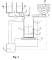
- Fig. 1 shows a first embodiment of a device for mixing and dosing of solid and liquid components of a corrosion inhibitor.
- the device comprises a batch container 1, which has a stirring device for mixing the components.
- the stirring device comprises a dissolver disk 2 and is driven by an arrangement of an axis and an electric motor 3.
- the electric motor 3 is mounted outside of the neck tank 1 at this, or on the container lid (not shown).
- the approach container 1 is made of steel and has lateral baffles 4, which provide for improved mixing, in particular perpendicular to the plane of the dissolver disc 2.
- a dissolver suction disk instead of the dissolver disk 2 to use.
- the device for mixing and dosing further comprises one or more storage containers 5a for liquid to pasty components of low to medium viscosity.
- the solvent here: water
- This may be commercially available impeller pumps, depending on the component used and double diaphragm pumps can be used. In the event that a pasty component is to be metered by means of a pump 6, this should be adapted to the material properties of the respective component.
- solid components of the anticorrosion agent such as. Zinc dust
- the device for mixing and dosing at least one reservoir 5b, the metering of solid components via a screw conveyor. 8
- a microprocessor unit 10 is provided, which is connected to the pump 6 and the screw conveyor 8. Furthermore, the batch container 1 is continuously weighed via a precision balance 11. By evaluating the measured data of the precision balance 11 in the microprocessor unit 10, the pumps 6 and the screw conveyor 8 are controlled in a clocked manner on the basis of the corrosion protection agent recipe in order to precisely dose the corresponding proportions of the components of the corrosion protection agent in one approach. In addition to the control of the dosage, it is also conceivable that the microprocessor unit 10 also controls the electric motor 3, whereby different stirring speeds or resting times can be taken into account. The connection of the microprocessor unit 10 with the devices is done via conventional control lines.
- the dissolver disc 2 is continuously kept rotating at a speed of 1000 rpm. After completion, a speed of 500 rpm is set.
- Fig. 2 shown second embodiment of the Means for mixing and dosing therefore shows a double-walled approach tank 1.
- the resulting gap between the two container walls 21 is filled with coolant.
- the batch container 1 can be tempered so via a heating / cooling unit (not shown), which is connected to the flow 22 and the return 23.
- the heating / cooling device should also be connected to the microprocessor unit 10 for monitoring and control.
- a third form of a storage container 5c which is particularly suitable for pasty components of the corrosion protection agent.
- the metering of the pasty component takes place via a squeezing device 9a, which is driven by an electric motor 9b.
- the electric motor 9b is connected to the microprocessor unit 10.
- squeezing device 9a in the embodiment of Fig. 1 in addition, for example, is used for dosing pasty aluminum.
- a plurality of storage containers 5b are used with corresponding screw conveyors 8 for a corrosion protection agent with a plurality of solid components.
- the corresponding storage containers and dosing agents should be selected in accordance with the composition of the anticorrosion agent.
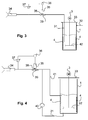
- FIG Fig. 3 A first embodiment of an application arrangement for applying the anticorrosive agent to a workpiece is shown in FIG Fig. 3 shown.
- the application arrangement has the already described approach container 1. This is first used within the previously described device for mixing and dosing. After completion of the anti-corrosion agent approach, the same batch container 1 is used within the application assembly. The use of the same batch container 1 is particularly advantageous for a quasi-continuous operation in the industrial manufacturing process. The replacement of the approach tank 1 between the two systems can be done manually, but also automatically.
- a suitable stirring device for example.
- a lid 33 closes the batch container pressure-tight.
- the Achsen preparer between the electric motor 3 and dissolver 2 is carried out accordingly pressure-tight.
- a pressure port 32 is provided for pressurizing the neck tank 1 with compressed air. When pressurized air is applied to the pressure port 32, the anticorrosion agent is expelled from the batch tank 1 via a conveyor pipe 31.
- the delivery pipe 31 connects the batch tank 1 with a spray gun 34.
- a suitable filter can be used between the batch tank 1 and the spray gun 34.
- a pressure reducer 35 is arranged between the preparation container 1 and the spray gun 34.
- the pressure reducer is controlled by a controller 36 which is connected to a pressure gauge 37.
- the controller 36 allows the setting of the respective spray pressure and regulates the pressure at the spray gun 34 via the pressure reducer 35 using the pressure gauge 37th
- the pressure reducer 35 comprises a displaceable on its longitudinal side of the pressure piston 38, which changes the cross section of a hose 39 depending on the position.
- the pressure reducer 35 includes for this purpose a suitable servomotor (not shown).
- the hose 39 has an inner diameter of 4 mm.
- a second embodiment of the application arrangement is shown.
- Application arrangement shown differs from that in Fig. 3 shown by the fact that a pump 40 is used to promote the corrosion protection agent from the approach tank 1 via the delivery line 31.
- the pump 40 is designed as a double diaphragm pump and promotes sucked corrosion protection agent to the spray gun 34 via suitable lines.
- the pump 40 can be operated continuously, even if the spray gun 34 is not active, a return line 41 is provided, passes through the excess corrosion inhibitor back into the batch tank 1.
- the return line 41 is returned below the level of the anticorrosion agent in the batch tank 1 (bottom-mirror method). To this In the same way, swirling of the corrosion protection agent in the batch container 1 can be achieved so that, depending on the nature of the anti-corrosion agent, the mixer can be dispensed with.
- Fig. 5 Such an embodiment of the application arrangement is in Fig. 5 shown.
- a third embodiment of an application arrangement has a connected to the feed line 31 pump 40 and a return line 41, with the excess corrosion inhibitor is returned to the batch tank 1.
- two spray guns 34 are present in the application assembly.
- Per spray gun 34, an arrangement of pressure reducer 35, controller 36 and pressure gauge 37 is provided to adjust the spray pressure at the respective spray gun 34 can. It is readily possible to arrange further spray guns 34 as shown.
- the pump 40 should then be selected appropriately to provide sufficient pressure.
- the use of multiple spray guns 34 is particularly advantageous in industrial production lines to allow coating of a workpiece from different directions, thereby ensuring uniform coating.
Landscapes
- Chemical & Material Sciences (AREA)
- Chemical Kinetics & Catalysis (AREA)
- Engineering & Computer Science (AREA)
- Wood Science & Technology (AREA)
- Materials Engineering (AREA)
- Organic Chemistry (AREA)
- Life Sciences & Earth Sciences (AREA)
- General Chemical & Material Sciences (AREA)
- Mechanical Engineering (AREA)
- Metallurgy (AREA)
- Inorganic Chemistry (AREA)
- Dispersion Chemistry (AREA)
- Paints Or Removers (AREA)
- Application Of Or Painting With Fluid Materials (AREA)
- Preventing Corrosion Or Incrustation Of Metals (AREA)
- Spray Control Apparatus (AREA)
Abstract
Description
- Die Erfindung betrifft ein Korrosionsschutzmittel mit siliziumbasiertem Bindemittel, ein Verfahren zur Herstellung und zum Anwenden des Korrosionsschutzmittels sowie Vorrichtungen zum Herstellen und Applizieren des Korrosionsschutzmittels.
- Korrosionsschutzmittel auf der Grundlage von Zinkstaub und silikatischen Bindemitteln sind seit langem bekannt. Sie werden als sogenannte Zinkstaub-Farben entweder in Form von Anstrichen aufgetragen oder als erste, einfache Korrosionsschutzbeschichtung, als sogenannte Primer, auf metallische Rohstoffe bzw. Halbwaren wie Bänder, Bleche und dergleichen aufgebracht.
- In beiden Ausführungen wird Zink als Mittel zum kathodischen Korrosionsschutz genutzt. Allerdings ist die Herstellung, Lagerung und Verarbeitung von Zinkstaub-Farben nicht einfach: Zink neigt äußerst schnell zum Absetzen und Aushärten, insbesondere in Gegenwart von Wasser. Dies macht sich in den von Anwendern besonders geschätzten Ein-Komponenten-Produkten besonders nachteilig bemerkbar. Ein-Komponenten-Produkte weisen daher in der Regel organische Lösungsmittel auf, um die Lagerfähigkeit der Zinkstaub-Farbe zu gewährleisten(
DE 25 15 305 ;CH 503 093 US 6,468,336 ). - Anstriche auf der Basis von Zinkstaub-Farben werden in hoher Schichtdicke aufgetragen. Diese Schichtdicke ergibt sich zum einen aus der Zusammensetzung der Farben, zum anderen ist die Schichtdicke wesentlicher Bestandteil des Schutzmechanismus, der dem Korrosionsschutz zugrunde liegt. Da bei Zinkstaub-Farben ein gewisses Risiko der Rißbildung über längere Zeit nicht völlig auszuschließen ist, wird u.a. versucht, den Nachteilen der Rißbildung durch große Schichtdicke zu begegnen. Da die Zinkstaub-Farben üblicherweise auf Konstruktionen im Außenbereich (Geländer, Gerüste, Brücken, Treppen, Schiffen und dergleichen) eingesetzt werden, kommt es hier auf Anforderungen an die Schichtdicke nicht an. Typisch für diesen Ansatz beschreibt z. B. die
US 4,162,169 ein Bindemittel, das zur Herstellung von Zinkstaub-Farben geeignet ist. Beschrieben wird der Einsatz von Zinkstaub-Farbe, die mit einem dichten Überzug (Topcoat) versehen ist. Das in derUS 4,162,169 vorgeschlagene Bindemittel enthält ein Silan, das beim Abbinden Methanol freisetzt. Es ist damit für Anwendungen geeignet, die im Freien, jedenfalls entfernt von Maschinen oder Produktionsanlagen stattfinden. Bei Einsatz in industriellen Anlagen müssen sonst Gesundheitsrisiken für das Personal und ggf. das durch das Methanol verursachte Explosionsrisiko beachtet werden. - Alternativ werden Zwei-Komponenten-Produkte angeboten, die vor Ort unmittelbar vor der Verwendung gebrauchsfertig gemischt werden. Zwei-Komponenten-Produkte sind insbesondere für gewerbliche Anwender geeignet, die größere Mengen von Zinkstaub-Farben einsetzen. Allerdings werden jeweils nur kleine Mengen von Zinkstaub-Farbe angerührt, die dann sofort verarbeitet werden müssen. Damit eignen sich Zinkstaub-Farben bisher nicht für Anwendungen, insbesondere industrielle Anwendungen, die eine kontinuierliche Verarbeitung von Zinkstaub-Farbe voraussetzen.
- Diesen Weg geht die
US 5,888,280 , die eine Zwei-Komponenten-Rezeptur vorschlägt, bei der Zinkstaub, ein Metallsilikat der Gruppe IA und ein carbonathaltiger, interner Härter in wässriger Lösung vorliegen. Dieses Beschichtungsmittel ist nicht nur als Primer einsetzbar, es soll bei höherem Einsatz von Zinkpartikeln und reduziertem Wasseranteil auch als vollwertiger Korrosionsschutz geeignet sein. Durch Freisetzen von CO2 soll der interne Härter den pH-Wert des Beschichtungsmittels herabsetzen und das Aushärten beschleunigen. - Weiter wird daran gearbeitet, die Korrosionsschutz-Wirkung von Zinkstaub-Farben zu verbessern, unter anderem, indem der Einsatz von leitfähigen Substanzen wie u.a. Eisenphosphid oder Eisenoxid-Verbindungen in Verbindung mit Zinkstaub-Farben vorgeschlagen wird. Ein typisches Beispiel für diese Entwicklung ist in der
US 6,468,336 dargestellt. - Es ist Aufgabe der Erfindung, ein Korrosionsschutzmittel vorzuschlagen, mit dem metallische Werkstücke bei gleichbleibender Qualität, kontinuierlich, sicher und energiesparend beschichtet werden können. Die Erfindung zielt dabei insbesondere auf den Einsatz von Bindemitteln ab, die bei der Verarbeitung der Zinkstaub-Farbe möglichst wenig oder keine organischen Komponenten (VOC: volatile organic components) freisetzen. Die Voraussetzung für VOC-freie und VOC-konforme Beschichtungsmittel, auf die sich auch die vorliegende Erfindung bezieht, sind definiert in der 31. BIMSCHV (Bundes-Immisionschutz-Verordnung) vom 21. August 2001(BGBl. I, Nr. 44 v. 24. Aug. 2001, S. 2180).
- Diese Aufgabe wird gelöst mit einem Korrosionsschutzmittel nach Anspruch 1, einem Verfahren zum Beschichten von Werkstücken gemäß Anspruch 19, einem Werkstück mit Korrosionsschutzmittel nach Anspruch 26, einem Verfahren zum Herstellen eines Korrosionschutzmittels nach Anspruch 30, einer Vorrichtung zum Herstellen eines Korrosionsschutzmittels nach Anspruch 38 und eine Applikationsanordnung nach Anspruch 46.
- Erfindungsgemäß weist das Korrosionsschutzmittel zwei Komponenten auf. Eine erste Komponente besteht im Wesentlichen aus Zinkstaub, ggf. mit einem Anti-Absetzmittel versetzt. Der Gewichtsanteil der ersten Komponente liegt - bezogen auf die Gesamtrezeptur- bei mindestens 40 Gewichts-%, vorzugsweise bei mindestens 60 Gewichts-%, besonders bevorzugt bei mindestens 80 Gewichts-% bis maximal 97 Gewichts-%. Der hohe Gehalt an Zinkstaub gewährleistet einen bisher für Zinkstaub-Beschichtungen nicht gekannten Korrosionsschutz.
- Die Zinkstaub-Partikel weisen einen durchschnittlichen Partikel-Durchmesser von bis zu 10 µm, bevorzugt von bis zu 8 µm auf. Bei dieser Partikelgröße ist für die mit diesem Partikeln aufzubauenden Trockenfilm-Stärken das Verhältnis von Durchmesser und spezifischer Oberfläche der Partikel optimal.
- Falls erforderlich, sind dem Zinkstaub Mittel zugesetzt, die ein unerwünschtes Kompaktieren des Zinkstaubs verhindern, sogenannte Anti-Absetzmittel. Besonders geeignet ist hier beispielsweise Zinkoxid oder amorphes SiO2. Der Anteil an Anti-Absetzmittel kann in der ersten Komponente bis zu 15 Gewichts-% bezogen auf die Menge an Zinkstaub betragen, vorzugsweise bis zu 10 Gewichts-%, besonders bevorzugt bis zu 5 Gewichts-%. Der Einsatz von Zinkoxid hat sich überraschenderweise beim Sprühen des Korrosionsschutzmittels als besonders vorteilhaft herausgestellt, weil Zinkoxid zu einem verbesserten Sprühverhalten beiträgt. Die Düsen der Sprühvorrichtung neigen bei Einsatz von Zinkoxid weitaus seltener zum Zusetzen. In den Angaben für das Zinkoxid ist berücksichtigt, dass der Zinkstaub herstellungsbedingt 1 bis 3 Gewichts-% Zinkoxid enthält.
- Eine zweite Komponente ist aus einem anorganischen, silziumbasierten Bindemittel, einem VOC-freien oder VOC-konformen Lösungsmittel und ggf. Partikeln zusammengesetzt, die zur Verbesserung des Korrosionsschutzes beitragen. Insbesondere Alkalimetallsilikate versetzt mit Siliziumdioxid, haben sich als geeignet erwiesen. Bevorzugt wird ein Bindemittel, bei dem der Anteil von Siliziumdioxids größer ist als der Anteil des Alkalioxids (Das Alkalisilikat wird hier auf der Basis von Alkalioxid berechnet). Das Verhältnis von SiO2 zu Alkalioxid beträgt mindestens 4:1, vorzugsweise mindestens 5:1, bevorzugt mindestens 6:1.
- Zur Anpassung an verschiedene Anwendungszwecke oder Verarbeitungsbedingungen können auch Mischungen von Alkalimetallsilikaten eingesetzt werden, beispielsweise eine Mischung aus Natrium- und Kaliumsilikaten, alternativ auch Lithiumsilikaten.
- Je nach den Erfordernissen des Anwendungsfalls können dem Bindemittel Co-Bindemittel zugesetzt sein. Dabei handelt es sich vorzugsweise um polymere Bindemittel, beispielsweise Methylsilikonharz oder verseifungsfreie Acrylate. Solche Bindemittel können zum Einstellen der Härte oder der Elastizität des Bindemittels dienen.
- Der Anteil des Bindemittels an der zweiten Komponente beträgt mindestens 3 Gewichts-% bis maximal 40 Gewichts-%, bevorzugt 10 Gewichts-% bis 20 Gewichts-%.
- Als VOC-freie oder VOC-konforme Lösungsmittel können sowohl Wasser, hochsiedende Lösungsmittel oder Mischungen davon eingesetzt sein. VOC-konforme Lösungsmittel sind insbesondere solche Lösungsmitteln, deren Siedepunkt (über 250°C) so hoch ist, dass sie bei der Verarbeitung keine organischen Substanzen freisetzen. Aus Gründen der Arbeitssicherheit wird bevorzugt, wenn Wasser als Lösungsmittel eingesetzt ist. Wasser gewährleistet zudem, dass das Korrosionsschutzmittel VOC-frei ist.
- Für das Korrosionsschutzmittel sind übliche, bekannte Pigmente einsetzbar. In der praktischen Anwendung wird jedoch oft angestrebt, ein gleichmäßiges, hochwertiges metallisches Aussehen der beschichteten Werkstücke zu erreichen. Daher werden dem Korrosionsschutzmittel meist metallische Partikel zugesetzt. Besonders geeignet sind solche aus passiviertem Aluminium, die allein zur optischen Gestaltung der Oberfläche eingesetzt werden. Aluminium kann in verschiedenen Formen eingesetzt werden. Bevorzugt ist der Einsatz von passivierten Aluminium-Flakes als Feststoff, der ggf. in die zweite Komponente eingebracht ist. Je nach den Anforderungen an das jeweilige Korrosionsschutzmittel können die Partikel zur Verbesserung des Korrosionsschutzes auch als dritte Komponente gelagert werden, die bei der Herstellung des Korrosionsschutzmittels mit der ersten und der zweiten Komponente zusammengeführt wird, so z. B. dann, wenn die Aluminiumpartikel als wässrige Paste vorliegen.
- Die Pigmente werden der zweiten Komponente des Korrosionsschutzmittels in einer Menge von mindestens 5 Gewichts-% bezogen auf die Gesamtmenge der zweiten Komponente zugesetzt. Bevorzugt werden mindestens 10 Gewichts-% bis mindestens 15 Gewichts-%, besonders bevorzugt bis 20 Gewichts-% Pigmente zugesetzt.
- Dem Korrosionsschutzmittel können -entweder in der ersten Komponente oder in der zweiten Komponente- weitere Zusätze beigefügt sein, um das Korrosionsschutzmittel an die Verarbeitungsbedingungen anzupassen oder um vorgegebene Gebrauchseigenschaften zu gewährleisten. Hier sind insbesondere Mittel zum Einstellen der Gleiteigenschaften bzw. Schmiermittel zu nennen. Sie werden vorzugsweise der zweiten Komponente zugesetzt, können aber auch in der ersten Komponente enthalten sein.
- Dem erfindungsgemäßen Beschichtungsmittel können als Additive auch feste oder flüssige Wachse als Emulsion oder Dispersion zugesetzt sein, um beispielsweise die Gleiteigenschaften der Beschichtung einzustellen. Es können übliche und bekannte Wachse eingesetzt sein, z. B. Wachse auf Basis von Polyethylen oder Polypropylen, Polytetrafluorethylen, aber auch natürliche Wachse wie Carnaubawachs oder Mischungen der vorgenannten Substanzen. Auch andere, die Schmier- und Gleiteigenschaften beeinflussende Substanzen wie Graphit, Molybdändisulfid oder Bornitrid können als Additive eingesetzt sein. Übliche Einsatzmengen für Schmier- oder Gleitmittel betragen bis zu 20 Gewichts-%, vorzugsweise bis zu 5 Gewichts-%, vorteilhaft bis zu 3 Gewichts-% bezogen auf die Gesamtrezeptur des Korrosionsschutzmittels.
- Das Beschichtungsmittel kann neben dem erfindungsgemäßen Bindemittel weiterhin Additive enthalten, die die Untergrundbenetzung, die Entschäumung, das Fließverhalten, die Entlüftung oder die Pigmentbenetzung beeinflussen, aber auch Mittel zur Flexibilisierung oder Katalysatoren können enthalten sein. Diese Additive können jeweils in Anteilen von 0,01 bis 8 Gewichts-% bezogen auf die Gesamtformulierung des Beschichtungsmittels zugesetzt sein.
- Im Rahmen der Erfindung können der zweiten Komponente beispielsweise mit gutem Effekt in Wasser dispergierbare oder mischbare Korrosionsinhibitoren zugesetzt sein, vorzugsweise stickstoffhaltige Verbindungen, insbesondere quarternäre Ammoniumsalze. Ein weiter bevorzugter Zusatz zu dem Beschichtungsmittel sind Borverbindungen, insbesondere aus der Gruppe der Borsäuren oder Boroxide, aber auch Molybdänverbindungen oder Verbindungen, die Phosphor enthalten. Diese Korrosionsinhibitoren werden in Mengen von 0,01 Gewichts-% bis 30 Gewichts-% bezogen auf die Gesamtformulierung zugesetzt, wobei die Untergrenze durch das Erreichen einer gewünschten Wirkung gegeben ist, während die Obergrenze aus Kostengründen gesetzt ist.
- Das erfindungsgemäße Korrosionsschutzmittel weist einen pH-Wert zwischen 6 und 12, bevorzugt zwischen 8 und 12 auf. Schon die alkalische Einstellung des Korrosionsschutzmittels trägt zur Schutzwirkung des Basecoats auf dem Werkstück bei, da sich in Gegenwart von Wasser ein basisches Milieu einstellt, dass einer Korrosion entgegenwirkt. Als besonderer Vorteil ist zudem herauszustellen, dass ein Korrosionsschutzmittel mit einem pH-Wert von 10 -12 das in der Komponente I enthaltene Zink kaum passiviert (vgl. B. Roathali, G. Cox und W. Littreal, "Metalls & Alloys", 3.73, 1963), so dass ein Maximum an kathodisch wirksamen Zinkpartikeln in der Beschichtung enthalten ist.
- Das erfindungsgemäße Korrosionsschutzmittel gewährleistet einen gegenüber bekannten Zinkstaub-Farben außerordentlich effizienten und langandauernden Rostschutz. Eine Beschichtung in einer Trockenschicht-Dicke von 10 µm gewährleistet eine Standzeit im Salzsprühtest nach DIN 50 0 21 von mindestens 200 Stunden, bei doppelter Beschichtungsdicke der Trockenschicht beträgt die Standzeit mindestens 500 Stunden. Der erreichbare Korrosionsschutz geht damit weit über die bisher erreichten Werte hinaus. Damit erweitert sich der Anwendungsbereich für das erfindungsgemäße Korrosionsschutzmittel über den Einsatz als einfaches Anstrichmittel. Das erfindungsgemäße Korrosionsschutzmittel kann mit verschiedensten Auftragsverfahren auf die zu beschichtenden Metalloberflächen aufgebracht werden. Aufgrund der hohen Wirksamkeit auch bei sehr geringen Schichtdicken ist das Mittel sehr sparsam und wirtschaftlich.
- Nach einer besonders bevorzugten Ausführungsform ist das erfindungsgemäße Korrosionsschutzmittel geeignet, mit einer weiteren Schicht, insbesondere einer farbgebenden Beschichtung überzogen zu werden. Eine solche Beschichtung, die auf dem erfindungsgemäßen Korrosionsschutzmittel haftet, ohne dessen Eigenschaften zu beeinträchtigen, ein sogenannter Topcoat, ist beispielsweise zusammengesetzt aus demselben Bindemittel, das in der zweiten Komponente des Korrosionsschutzmittels enthalten ist. Auch hier kann das Bindemittel ergänzt sein um ein Co-Bindemittel, vorzugsweise ein polymeres Co-Bindemittel, besonders ein Methylsilikonharz oder ein verseifungsfreies Acrylat.
- Nach einer weiter bevorzugten Ausführung ist dieser Topcoat mit farbgebenden Pigmenten, zum Beispiel mit Aluminiumpigmenten, Ruß oder Eisenpigmenten versehen. Der Topcoat kann VOC-konform sein, also beschränkte Mengen organischer Substanzen enthalten, die beim Verarbeiten oder Aushärten des Topcoats freigesetzt werden. Bevorzugt ist der Topcoat jedoch ebenfalls VOC-frei.
- Damit auch empfindliche Werkstoffe beschichtet werden können, sind das Korrosionsschutzmittel und ggf. der Topcoat vorteilhaft so eingestellt, dass das Trocknen bzw. Aushärten bei Temperaturen von bis zu 120°C erfolgt, bevorzugt bis zu 80°C, besonders bevorzugt bis zu 40 °C.
- Gegenstand der Erfindung ist weiter ein Verfahren zum Aufbringen einer korrosionsschützenden Beschichtung auf ein metallisches Werkstück. Dieses Verfahren wird als eigenständiger erfinderischer Beitrag zur Erfindung angesehen.
- Das erfindungsgemäße Verfahren zum Beschichten von metallischen Werkstücken sieht vor, die Oberfläche des metallischen Werkstücks ggf. zu reinigen, dann mit einem VOC-freien (bevorzugt) oder einem VOC-konformen Primer zu beschichten, das Werkstück dann nach dem Trocknen des Primers mit einem Korrosionsschutzmittel nach mindestens einem der Ansprüche 1 bis 10 zu beschichten und abschließend das Korrosionsschutzmittel zu trocknen.
- Das Auftragen des Primers, der im einfachsten Fall aus einer Wasserglas-Lösung oder einem Co-Binder besteht, wie er für das Korrosionsschutzmittel beschrieben ist, verbessert die Haftung des Korrosionsschutzmittels auf dem Werkstück und gewährleistet damit einen langdauernden Korrosionsschutz des Werkstücks.
- Die Reinigung des Werkstücks wird in der Regel erforderlich sein, weil Rückstände aus vorangehenden Bearbeitungsschritten die Haftung der Korrosionsschutz-Beschichtung hindern. Grundsätzlich ist jede Form von Oberflächen-Reinigung geeignet, einen Untergrund für die erfindungsgemäße Beschichtung zu schaffen. Wichtig ist aber, dass auch schonende Reinigungsverfahren wie sie z. B. für die Vorbereitung empfindlicher Werkstoffe erforderlich sind, ebenfalls einen geeigneten Untergrund für die vorerwähnte Beschichtung mit Korrosionsschutzmitteln bieten. Insbesondere die Reinigung temperatur- und /oder säureempfindlicher Werkstoffe wie z. B. Spezialstähle mittels Bürsten, Ultraschall, Laugen- und/oder Lösemittelbad oder Dampfreinigung oder einer Folge oder Kombination dieser Reinigungsschritte schafft Oberflächen, die zur Beschichtung bestens geeignet sind.
- Auf die so gereinigte Oberfläche des Werkstücks wird jetzt mindestens abschnittsweise ein Primer aufgebracht. Zahlreiche Primer sind geeignet, beispielsweise Co-Binder, die mit dem Bindemittel des Korrosionsschutzmittels oder des Topcoats einsetzbar sind.
- Bevorzugt handelt es sich bei dem Primer um eine VOC-freie Lösung, z. B. eine 4-%ige Wasserglas-Lösung, ggf. mit Additiven, die unproblematisch zu verarbeiten ist. Der Primer kann im einfachsten Fall ohne weitere Additive aufgetragen werden, üblicherweise ist er aber mit weiteren Additiven, z. B. mit Benetzungsmitteln und ggf. Korrosionsinhibitoren versetzt. Bevorzugt werden bis zu 5 Gewichts-% Benetzungsmittel und/oder Korrosionsschutzmittel eingesetzt, vorteilhaft bis zu 0,05 Gewichts-%. Diese Beschichtung wird anschließend getrocknet. Die Trocknung erfolgt mittels Lufttrocknung bevorzugt zwischen Raumtemperatur und 100 °C, also besonders einfach und preiswert. Die Schichtdicke des getrockneten Primers beträgt zwischen 100 nm und 3 µm.
- Auf den getrockneten Primer wird erfindungsgemäß mindestens abschnittsweise eine Schicht des vorstehend beschriebenen Korrosionsschutzmittels aufgetragen. Das Korrosionsschutzmittel kann mit beliebigen Auftragsverfahren, insbesondere Sprühen, Walzen, Gießen, Streichen, Rakeln, Rollen, Tauch-Schleudern oder Tauch-Ziehen aufgebracht werden. Die Beschichtung mit dem Korrosionsschutzmittel erfolgt zweckmäßig unmittelbar, spätestens aber bis zu 4 Stunden nach dem Trocknen des Primers, um einen optimalen, langfristig beständigen Korrosionsschutz zu gewährleisten. Das Korrosionsschutzmittel ist bei Raumtemperatur schnell berührungsfest, bereits nach ca. 30 bis 120 Sekunden ist es auf der Oberfläche des Werkstücks angetrocknet. Die eigentliche Aushärtezeit beträgt je nach Bindemittel und Schichtdicke sowie Anteil des Zinkstaubs zwischen 24 Stunden und 72 Stunden, im Extremfall kann die Aushärtezeit bis zu 14 Tagen betragen.
- Die zur Trocknung erforderlichen Temperaturen liegen sowohl für den Primer als auch für das Korrosionsschutzmittel nicht über 120 °C, bevorzugt nicht über 80 °C, besonders bevorzugt nicht über 40 °C, vorteilhaft nicht über Raumtemperatur. Das Trocknen bzw. Aushärten kann sowohl für den Primer als auch für das Korrosionsschutzmittel mit Luft erfolgen. Bevorzugt wird mit stark erhöhter Luftgeschwindigkeit getrocknet, die z. B. in so genannten Seitenverdichtern erzeugt wird. Diese Form der Trocknung erfordert nur geringen Energieaufwand und verhältnismäßig geringen apparativen Aufwand.
- Das nach dem vorstehend beschriebenen Verfahren beschichtete Werkstück ist langfristig gegen Korrosion geschützt, auch wenn es aggressiven Umweltbedingungen ausgesetzt ist. Beispielsweise eignet sich die oben beschriebene Beschichtung aus Primer und Korrosionsschutzmittel sehr gut, um Bremsscheiben zu beschichten, die eine Beständigkeit im Salzsprühtest von mehr als 500 Stunden aufweisen müssen. Bremsscheiben werden bisher mit bekannten Korrosionsschutzmitteln beschichten, die zum vollständigen Aushärten über längere Zeit auf Temperaturen über 300 °C erhitzt werden müssen. Dabei kommt es häufig zu einem Verformen der Bremsscheiben, was für diese Produkte nicht zulässig ist. Bekannte Beschichtungen führen daher zu einem verhältnismäßig hohen Ausschuss. Andere Bauteile sind z. B. aus einem temperaturempfindlichen Metall oder aus Guss hergestellt. Diese Werkstoffe ändern ihre Eigenschaften bei Erwärmung auf über 180 °C wesentlich. Damit scheiden konventionelle Beschichtungsverfahren für einen weiten Kreis von Korrosionsschutzmittel aus, die zum Aushärten der Beschichtung immerhin noch Temperaturen von über 160 °C, oft über 200 °C einsetzen. Auch hier eröffnet das erfindungsgemäße Korrosionsschutzmittel deutlich verbesserte Möglichkeiten für einen umfassenden kathodischen Korrosionsschutz.
- Für das erfindungsgemäße Werkstück wird eine Trockenschicht-Dicke des Korrosionsschutzmittels nach dem Aushärten von 1 µm bis 100 µm, vorzugsweise von 15 µm bis 60 µm, besonders bevorzugt von 20 µm bis 40 µm angestrebt.
- Das Korrosionsschutzmittel aus zwei, ggf. drei Komponenten kann auf besonders einfache Weise gebrauchsfertig hergerichtet werden. Aus dem Stand der Technik ist bekannt, dass Zinkstaub in das Bindemittel eingerührt wird. Dieses Beschichtungsmittel muss dann sofort verarbeitet werden. Aufgrund der außerordentlich kurzen Verarbeitungszeit (Topfzeit) wird bei bekannten Produkten stets batchweise gearbeitet.
- Diese Form der Aufbereitung des Korrosionsschutzmittels ist für industrielle Verarbeitungsprozesse nicht geeignet. Eine besser an den kontinuierlichen Bedarf angepasste Versorgung mit dem erfindungsgemäßen Korrosionsschutzmittel ist jedoch bisher nicht verfügbar gewesen. Versuche haben gezeigt, dass eine quasi-kontinuierliche Herstellung des Korrosionsschutzmittels beim Anwender geeignet ist, einen kontinuierlichen Bedarf gut zu bedienen.
- Aufgrund der oben genannten Aufgabe wird im Rahmen der erfindungsgemäßen Lösung als eigenständiger Bestandteil für das Herstellen von Beschichtungsmitteln mit festen und flüssigen Komponenten das nachfolgend erläuterte Verfahren bereitgestellt.
- Hierbei wird zunächst eine Teilmenge der flüssigen Komponenten des Korrosionsschutzmittels für einen Ansatz des Beschichtungsmittels in einen Ansatzbehälter gegeben. Wie bereits eingangs erwähnt, kann es sich bei den flüssigen Komponenten bspw. um die flüssige Komponente des Beschichtungsmittels mit Bindemittel und weiteren Additiven wie Haftvermittler, Benetzungsmittel, Verdicker, Entschäumer, Entlüftungsmittel, Pigmentbenetzer, Korrosionsinhibitoren aber auch Mittel zur Flexibilisierung oder Katalysatoren handeln. Es kann aber auch ein geeignetes Lösungsmittel oder Wasser vorgelegt werden.
- Anschließend wird die feste Komponente zugegeben und zur gleichmäßigen Durchmischung von fester und flüssiger Komponente eine Homogenisierungsphase durchgeführt.
- Unter dem Begriff "feste Komponenten" sind im Rahmen der vorliegenden Erfindung insbesondere partikuläre Stoffe wie Metallpartikel/Flakes, trockene Pigmente und Füllmaterial verstanden. Auch pastöse Komponenten, also solche, die nicht oder nur sehr begrenzt fließfähig sind, sind im Zusammenhang der vorliegenden Erfindung als feste Komponenten verstanden.
- Nach dem Homogenisieren des Ansatzes für das Beschichtungsmittel wird die Restmenge der flüssigen Komponente zugegeben und ggf. - je nach Viskosität der einzelnen Komponenten - mit dem Ansatz vermengt.
- Nach einer besonders bevorzugten Ausführungsform erfolgt das Abmessen und Mischen der festen und flüssigen Komponenten durch eine automatische Steuerung. Diese Steuerung regelt nach einer vorteilhaften Weiterbildung auch die Einhaltung optimaler Verfahrensparameter, bspw. Temperatur, Druck, Mischdauer und Intensität des Mischens.
- Der Vorteil des Verfahrens liegt insbesondere bei der Herstellung von Beschichtungsmittel mit hohem Anteil an festen Komponenten, wie z. B. bei dem Korrosionsschutzmittel gemäß der vorliegenden Erfindung. Das Verfahren erlaubt eine quasi-kontinuierliche Versorgung mit dem erfindungsgemäßen Korrosionsschutzmittel, bspw. innerhalb industrieller Verarbeitungsprozesse. Hierbei wird zwar ein Ansatz an Korrosionsschutzmittel in einem "Batch" hergestellt, durch die besondere, bevorzugt automatische Ausgestaltung des Verfahrens ist jedoch eine Versorgung mit Korrosionsschutzmittel in einem kontinuierlichen Industrieprozess, bspw. innerhalb einer Beschichtungsanlage einer Fertigungsstraße möglich. Es ist möglich, besonders gleichmäßige Ansätze mit außerordentlich hohen Anteilen der festen Komponente wirtschaftlich herzustellen, auch dann, wenn ausschließlich auf VOC-freie oder ggf. VOC-konforme Bestandteile zurückgegriffen wird.
- Die Bestimmung der Teilmenge der flüssigen Komponenten, die zu Beginn des Verfahrens in den Behälter gegeben wird, ist grundsätzlich abhängig von dem Verhältnis der flüssigen zu den festen Komponenten und insbesondere der Viskosität der flüssigen Komponenten. Die Teilmenge sollte so gewählt werden, dass während der Homogenisierungsphase eine homogene Paste mittlerer bis hoher Viskosität erhalten wird, wodurch eine gute Vermengung durch Annäherung der Viskositäten der einzelnen Komponenten erreicht wird. Beim Herstellen des erfindungsgemäßen Korrosionsschutzmittels mit extrem hohem Anteil an Zinkstaub (z. B. über 90 Gewichts-%) und einem VOC-konformen Lösungsmittel, beträgt die Teilmenge bevorzugt ungefähr ein Drittel der gesamten Menge der flüssigen Komponenten. Hierbei wird neben einer sehr guten Homogenisierung auch ein Vereinzeln agglomerierter Zinkpartikel erreicht.
- Je nach Beschaffenheit insbesondere der flüssigen Komponenten, wird bevorzugt während des Zugebens der festen Komponenten und/oder während der Homogenisierungsphase der Ansatz regelmäßig vermengt. Hierbei können grundsätzlich sämtliche geeigneten Vorrichtungen und Verfahren eingesetzt werden, wie zum Beispiel Vermengen durch Gasverwirbelung oder kontinuierliches bzw. regelmäßiges Umpumpen des Ansatzes. Insbesondere ist es bevorzugt, dass der Ansatz regelmäßig oder kontinuierlich verrührt wird. Hierbei können übliche Rührvorrichtungen, je nach Größe des Ansatzbehälters, wie bspw. Magnetrührer, Dissolverscheiben oder ein Ultraturrax eingesetzt werden. Um ein Absetzen der festen Komponenten im Beschichtungsmittel zu vermeiden ist es weiterhin bevorzugt, dass auch während des Zugebens der Restmenge der flüssigen Komponenten sowie einer etwaigen nachfolgenden Stand-/Rührzeit, der Ansatz regelmäßig vermengt wird.
- Beim Verrühren des Ansatzes wird die Qualität des Mischvorgangs durch die Auswahl des Rührers und der Drehzahl bestimmt. Grundsätzlich sollte die Drehzahl daher anhand der Umfangsgeschwindigkeit in Abhängigkeit der zu homogenisierenden Mittel gewählt werden. Experimentelle Ergebnisse des Anmelders bestätigen z. B., dass eine Drehzahl zwischen 100 und 1500 U/min und bevorzugt 1000 U/min bei Verwendung einer Dissolverscheibe besonders vorteilhaft zur Herstellung eines Beschichtungsmittels ist. Insbesondere bevorzugt ist die Drehzahl regelbar, so daß bei den einzelnen Verfahrensschritten unterschiedliche Drehzahlen eingestellt werden können.
- Bevorzugt wird die Temperatur des Beschichtungsmittel-Ansatzes während des Verfahrens zwischen 4°C und 40°C gehalten. Hierzu kann der Ansatzbehälter geeignet ausgebildet sein, bspw. mit üblichen Heiz-/Kühlvorrichtungen. Geeignet sind z. B. doppelwandige Ansatzbehälter, die von einem Heiz- oder Kühlmedium durchströmt werden. Je nach Bindemittelsystem kann es zweckmäßig sein, den Behälter während des Misch-und Dosierverfahrens mit einem festgelegten Über- oder Unterdruck zu beaufschlagen. Insbesondere kann bei Anlegen eines Vakuums z. B. eine Entschäumung und damit eine gute Homogenisierung des Beschichtungsmittels erreicht werden. Bevorzugt ist hierbei ein Unterdruck von ca. 1/2 bar unter Atmosphärendruck.
- Nach einer Weiterbildung der Erfindung ist es bevorzugt, dass mit oder nach Zugabe der Restmenge der flüssigen Komponenten weitere feste und/oder flüssige Komponenten und insbesondere feste und/oder flüssige Zusatzstoffe zugegeben werden. Beispielsweise können Pigmente, insbesondere Metallpartikel und/oder Flakes, wie bspw. Aluminiumflakes in fester oder pastöser Form, aber auch Schmiermittel, Benetzungsmittel, Verdicker oder Haftvermittler so wie sie vorstehend im Zusammenhang mit der Zusammensetzung der Korrosionsschutzmittels beschrieben werden, zugegeben werden. Je nach Zusatzstoff sollte bevorzugt auch während der Zugabe von Zusatzstoffen und/oder auch danach der Beschichtungsmittelansatz weiter vermengt bzw. verrührt werden. Für ein Verrühren nach Komplettierung des Beschichtungsmittels wird bevorzugt eine Drehzahl im Bereich von bis zu 500 U/min verwendet.
- Aufgrund der speziellen Rezeptur eines VOC-konformen Korrosionsschutzmittels und dem dadurch bedingten besonderen Herstellungsverfahren wird im Rahmen der erfindungsgemäßen Lösung als eigenständiger Bestandteil zum Herstellen des erfindungsgemäßen Korrosionsschutzmittels eine Vorrichtung zum Mischen und Dosieren von festen und flüssigen Komponenten des Korrosionsschutzmittels bereitgestellt. Diese Vorrichtung ist versehen mit Mitteln zum Abmessen der Mengen der jeweiligen Komponente des Korrosionsschutzmittels, einem Ansatzbehälter sowie einer Mischvorrichtung und ggf. Mitteln zum Steuern des Verfahrens. Unter Verwendung einer derartigen Vorrichtung ist die Durchführung des vorgenannten Verfahrens zur Herstellung des erfindungsgemäßen Korrosionsschutzmittels in vorteilhafter Weise leicht möglich.
- Zum Abmessen der Mengen der jeweiligen Komponenten des Korrosionsschutzmittels sind grundsätzlich sämtliche übliche Vorrichtungen, wie Waagen, Pumpen oder Durchflussmesser geeignet. Beispielsweise können die festen Komponenten, wie Zinkstaub, unter Wiegen des Korrosionsschutzmittelansatzes dosiert beigegeben werden. Hierbei kann der Ansatzbehälter beispielsweise auf einer Waage angeordnet sein, um das Gewicht des Ansatzbehälters bestimmen zu können. Vor Zugabe der jeweiligen Menge wird das Gewicht des Ansatzbehälters bestimmt und die Differenz von dem jeweiligen Meßwert beim Zugeben der Komponente bestimmt. Bei flüssigen Komponenten können auch bspw. getaktete Pumpen oder Durchflussmesser/Sensoren zum Abmessen der Mengen vorteilhaft sein. Auch bei flüssigen Komponenten kann eine Waage eingesetzt sein. Die Meßunsicherheit sollte maximal 2%, bevorzugt 1% nicht überschreiten, um die Rezeptur des erfindungsgemäßen Korrosionsschutzmittels einhalten zu können. Die Auswahl der jeweiligen Vorrichtungen zum Abmessen richtet sich nach den jeweiligen Bedingungen des zu messenden Substrats.
- Die Vorrichtung zum Mischen des Korrosionsschutzmittels weist ferner einen Ansatzbehälter zur Aufnahme des Korrosionsschutzmittelansatzes sowie eine Mischvorrichtung auf. Der Ansatzbehälter sollte hierbei nach Möglichkeit leicht austauschbar sein, um in einer industriellen Fertigung im quasi-kontinuierlichen Betrieb eingesetzt werden zu können. Es ist hierbei vorteilhaft möglich, den Ansatzbehälter nach Herstellung des Korrosionsschutzmittels direkt in einer Applikations-/Beschichtungsanordnung zu verwenden.
- Nach einer Weiterbildung der Erfindung ist der Ansatzbehälter ein Druckgefäß. Je nach Applikationsvorrichtung oder bei Verwendung von flüchtigen Komponenten innerhalb des Korrosionsschutzmittels ist ein Druckgefäß vorteilhaft. Bevorzugt weist die Vorrichtung Mittel zum konstant halten der Behältertemperatur des Ansatzbehälters auf. Hierdurch kann auch bei exotherm reagierenden Lösemittel- oder Bindemittelsystemen die Einhaltung des geforderten Temperaturbereichs eingehalten werden. Hierzu kann der Ansatzbehälter doppelwandig ausgeführt sein, wobei der dadurch zwischen den beiden Behälterwänden entstehende Hohlraum mit Kühlflüssigkeit oder Wasser durchströmt werden kann. Mit einem üblichen Heiz-/Kühlaggregat kann so ein Temperieren des Ansatzes erfolgen.
- Die Mischvorrichtung sollte so ausgelegt sein, um ein regelmäßiges oder bevorzugt ein kontinuierliches Vermengen des Korrosionsschutzmittelansatzes im Ansatzbehälter zu erreichen. Geeignete Mischvorrichtungen können bspw. so ausgelegt sein, dass am Ansatzbehälter angebrachte Gasdüsen durch Anlegen eines entsprechenden Gasdrucks den Korrosionsschutzmittelansatz verwirbeln. Ebenfalls ist es denkbar, über eine Pumpe den Korrosionsschutzmittelansatz in einem geschlossenen Kreislauf aus dem Ansatzbehälter zu entnehmen und dem Ansatzbehälter wieder beizugeben (Umpumpen).
- Bevorzugt ist die Mischvorrichtung eine Rührvorrichtung. Entsprechende Rührvorrichtungen weisen in der Regel einen Rührer, wie bspw. eine Dissolverscheibe oder einen Wendelrührer auf, welche über einen geeigneten Antrieb bewegbar sind. Der Antrieb kann beispielsweise ein Elektromotor sein. Insbesondere ist es bevorzugt, daß der Rührer so ausgelegt ist, daß ein Vermengen einerseits in der Ebene des Rührers, aber auch senkrecht dazu erfolgt. Mit einem derartigen Rührwerkzeug kann gerade bei der Vermengung von Korrosionsschutzmitteln mit hoher Konzentration an festen Komponenten eine gute Vermengung erreicht werden. Der Rührer sollte weiterhin bevorzugt an die Geometrie des jeweiligen Ansatzbehälters angepasst sein.
- Zur weiteren Verbesserung der Vermengung des Korrosionsschutzmittelansatzes ist es ferner bevorzugt, dass der Ansatzbehälter in der Technik übliche Verwirbelungsmittel, bspw. Schikanen an der Innenseite aufweist.
- In einer Weiterbildung der Erfindung sind Fördermittel zum Fördern einer festen oder flüssigen Komponente aus dem jeweiligen Vorratsbehälter in den Ansatzbehälter vorgesehen. Insbesondere in industriellen Fertigungsstraßen ist ein mindestens teilweise automatisches Mischen und Dosieren der Komponenten des Beschichtungsmittelansatzes vorteilhaft. Da ferner in der Regel innerhalb einer Rezeptur die Toleranzen für die einzelnen Komponenten relativ gering sind, lassen sich so Dosierungsfehler vermeiden. Hierbei ist es grundsätzlich bevorzugt, dass sämtliche Komponenten des Beschichtungsmittels über Fördermittel in den Ansatzbehälter zu fördern sind. Um eine verbesserte Dosierung zu ermöglichen, sollte die Förderleistung der Fördermittel bevorzugt regelbar sein.
- Das jeweilige Fördermittel ist abhängig von der zu befördernden Komponente. Bei flüssigen Komponenten sind in der Regel Pumpen mit Rohr- oder Schlauchleitungen vorteilhaft. Für trockene und pastöse Komponenten des Beschichtungsmittels wird bevorzugt ein Schneckenförderer eingesetzt. Insbesondere bei der Verwendung von Metallpartikeln, wie bspw. feinstem Zinkstaub, ist eine Dosierung oftmals schwer möglich und aufgrund der durch das geringe Gewicht der Partikel sehr hohen Zerstäubungsneigung mit starker und gesundheitsschädlicher Emissionsbildung verbunden. Daher sind insbesondere hier Schneckenförderer vorteilhaft. Weiterhin wäre es ebenfalls denkbar, feste partikuläre Komponenten und insbesondere Metallpartikel wie Zinkstaub mittels Druckluft über Rohrleitungen zum Ansatzbehälter zuzuführen. Zweckmäßig kann, insbesondere für pastöse Komponenten, das Fördermittel eine Auspressvorrichtung sein.
- Bevorzugt weist die Vorrichtung zum Mischen und Dosieren Steuerungsmittel zur Steuerung der Dosierung auf. Derartige Steuermittel erleichtern die sichere und genaue Dosierung deutlich. Neben der Steuerung der Dosierung ist es natürlich auch möglich, dass die Steuerungsmittel weitere Prozessparameter, wie bspw. das Mischen durch entsprechende Messung von Viskositäten überwachen und einstellen. Ebenfalls können derartige Steuermittel so ausgelegt sein, dass diese, je nach Absetzverhalten des Korrosionsschutzmittels, die Topfzeit selbständig überwachen und so in die Prozesssteuerung einer Applikations-/Beschichungsanlage integriert werden. Ebenfalls ist es denkbar, Mittel zur Überwachung des Füll-/Niveaustandes vorzusehen, um bei Unterschreiten eines bestimmten Füllstandes innerhalb der Applikations-/Beschichtungsanlage automatisch das Mischen eines neuen Korrosionsschutzmittelansatzes in der Vorrichtung zum Mischen und Dosieren zu starten. Steuerungsmittel sind in der Prozesstechnik industriell verfügbar, insbesondere geeignet sind bspw. SPS-Steuerungen oder Mikroprozessorsteuerungen.
- Das Aufbringen des erfindungsgemäßen Korrosionsschutzmittels ist, wie eingangs erläutert, aufgrund der Eigenschaften des VOC-konformen Korrosionsschutzmittels bezüglich Absetzverhalten und kurzer Trockenzeit schwierig. Hierdurch können Rohrleitungen und Vorrichtungen schnell verstopfen. Aufgrund dieser besonderen Problematik bei der Verarbeitung des erfindungsgemäßen VOC-konformen Korrosionsschutzmittels wird daher im Rahmen der erfindungsgemäßen Lösung als eigenständiger Bestandteil für das Bereitstellen einer Korrosionsschutzbeschichtung eine Applikationsanordnung zum Aufbringen von Korrosionsschutzmittel auf ein Werkstück bereitgestellt. Die Applikationsanordnung weist hierzu einen Ansatzbehälter, Fördermittel, mindestens einen mit dem Ansatzbehälter verbundenen Druckminderer und eine mit dem Ansatzbehälter verbundene Sprühvorrichtung auf.
- Mit einer derartigen Anordnung ist es vorteilhaft möglich, das erfindungsgemäße Korrosionsschutzmittel auf ein Werkstück aufzutragen. Der Ansatzbehälter sollte hierbei so ausgelegt sein, dass ein batchweises Verarbeiten innerhalb der Topfzeit der jeweiligen Korrosionsschutzmittelzusammensetzung möglich ist. Die Größe des Ansatzbehälters sollte daher gemäß den Anforderungen in der jeweiligen Beschichtungsanlage gewählt werden.
- Es ist denkbar, denselben Ansatzbehälter innerhalb der Vorrichtung zum Mischen und Dosieren und der Applikationsanordnung zu verwenden. Der Ansatzbehälter sollte geeignete Anschlüsse zum Entnehmen des Korrosionsschutzmittels aufweisen. Hierzu weist die Applikationsanordnung geeignete Fördermittel auf, bspw. können alle üblichen Fördermittel, wie bspw. geeignete Förderpumpen hierfür eingesetzt sein. Derartige Fördermittel sollten so ausgelegt sein, dass die üblicherweise vorhandenen Leitungen zwischen Ansatzbehälter und Druckminderer/Sprühvorrichtung mit Korrosionsschutzmittel unter einem geeigneten Betriebsdruck versorgt werden können. Der Betriebsdruck sollte hierbei grundsätzlich abhängig von der jeweiligen Leitungslänge gewählt werden. Für übliche Beschichtungsanlagen hat sich ein Betriebsdruck von 1-2 Bar als geeignet gezeigt. Insbesondere sollte der Betriebsdruck deshalb nicht zu gering gewählt werden, um ein Absetzen der festen Komponenten des Korrosionsschutzmittels oder ein Zusetzen der Leitungen zu vermeiden. Bei dem Auftragen des Korrosionsschutzmittels auf ein Werkstück ist insbesondere ein HVLP-Verfahren bevorzugt. Daher ist das Einstellen eines exakten Sprühdrucks, üblicherweise zwischen 0,3 und 0,4 bar notwendig. Um den entsprechenden Sprühdruck einzustellen ist ein Druckminderer vorgesehen. Der Druckminderer sollte den durch das jeweilige Fördermittel erzeugen Betriebsdruck sicher regeln können. Bevorzugt ist der Druckminderer zwischen dem Ansatzbehälter und der damit verbundenen Sprühvorrichtung zwischengeschaltet. Beim Einsatz mehrerer Sprühpistolen in einer Applikationsanordnung sollte je Sprühvorrichtung ein Druckminderer vorhanden sein, um den Sprühdruck an jeder Sprühpistole optimal einstellen zu können. Hierbei sollte der Leitungsweg zwischen Druckminderer und Sprühpistole möglichst kurz gehalten werden. Derartige Druckminderer sind im Bereich der Fluidtechnik industriell verfügbar. Druckminderer und Sprühvorrichtung sollten so ausgestaltet sein, dass ein Zusetzen im Betrieb vermieden wird.
- Bevorzugt ist der Druckminderer daher kontaktlos ausgeführt, d.h. der Druckminderer steht nicht in unmittelbarem Kontakt mit dem im Betrieb verwendeten Korrosionsschutzmittel. Eine derartige Ausgestaltung des Druckminderers ist insbesondere daher vorteilhaft, da übliche Membrandruckminderer die Eigenschaft zeigen, dass sich bei dem erfindungsgemäßen Beschichtungsmittel mit festen und flüssigen Komponenten, Teile der festen Komponenten innerhalb des Druckminderers sammeln und so zu einem frühzeitigen Zusetzen des Druckminderers führen. Insbesondere ist es daher bevorzugt, dass der Ansatzbehälter mindestens abschnittsweise mittels einer Schlauchleitung mit der Sprühpistole verbunden ist und der Druckminderer derart ausgelegt ist, dass der Querschnitt der Schlauchleitung mindestens abschnittsweise variierbar ist.
- Durch eine derartige Ausgestaltung ist eine einfache Druckregulierung möglich. Der Druckminderer kann hierzu die Schlauchleitung bspw. mittels eines Pneumatikzylinders quetschen. Die Schlauchleitung sollte daher entsprechend der Ausführung des Druckminderers geeignet beschaffen sein, und insbesondere elastisch sein. Bevorzugt wird ein Schlauch verwendet, welcher einen Innendurchmesser zwischen 2 mm - 10 mm aufweisen sollte.
- Besonders bevorzugt ist die Sprühvorrichtung derart ausgebildet, daß der im Betrieb erzeugte Zerstäuberluftstrom außerhalb der Sprühvorrichtung das Korrosionsschutzmittel zerstäubt. Das Korrosionsschutzmittel kommt folglich vorteilhaft erst außerhalb der Sprühvorrichtung mit dem Zerstäuberluftstrom in Kontakt. Die Sprühvorrichtung ist hierfür entsprechend ausgebildet, insbesondere kann die Düse eine einstellbare Öffnungsgröße aufweisen. Entsprechende Versuche des Anmelders zeigen, daß insbesondere eine Düsengröße zwischen 0,5 mm - 1,2 mm bei Verwendung einer "Stem-S"-Düse vorteilhaft ist. Selbstverständlich kann auch jede andere geeignete Düse eingesetzt werden.
- Neben dem Zerstäuberluftstrom wird außerhalb der Sprühvorrichtung auch ein formgebender Luftstrom bereitgestellt, welcher die restliche, für das Versprühen des Korrosionsschutzmittels notwendige Luftmenge im Betrieb bereitstellt und den Sprühstrahl formt.
- Die derartige Ausgestaltung der Sprühvorrichtung ist insbesondere bei dem erfindungsgemäßen Korrosionsschutzmittel vorteilhaft, da dieses bei Kontakt mit Luft zügig aushärtet. Dadurch, daß die zum Zerstäuben benötigte Luftmenge im wesentlichen erst außerhalb der Sprühvorrichtung zugesetzt ist, kann ein Zusetzen der Sprühvorrichtung in dieser Weise vorteilhaft vermieden werden.
- Nach einer bevorzugten Weiterbildung weist der Ansatzbehälter, auch wenn er in der Applikationsanordnung eingesetzt ist eine Mischvorrichtung auf. Je nach Zusammensetzung des Korrosionsschutzmittels kann es vorteilhaft sein, den im Ansatzbehälter enthaltenen Korrosionsschutzmittelansatz regelmäßig zu vermengen bzw. kontinuierlich zu vermengen. Hierdurch kann gerade bei Korrosionsschutzmittelzusammensetzungen mit hohem Anteil an festen Komponenten, wie bspw. dem erfindungsgemäßen VOC-konformen Korrosionsschutzmittel, ein vorzeitiges Absetzen vorteilhaft vermieden werden. Entsprechende einsetzbare Mischvorrichtungen wurden bereits bei der Erläuterung der Vorrichtung zum Mischen und Dosieren diskutiert, worauf hier Bezug genommen wird.
- Insbesondere ist es hierbei bevorzugt, dass der in der Applikationsanordnung eingesetzte Ansatzbehälter ein Druckgefäß ist und eine Vorrichtung zum kontinuierlichen Rühren des Korrosionsschutzmittels aufweist. Durch die Ausbildung des Ansatzbehälters als Druckgefäß ist es möglich, mit geeigneten Fördermitteln, bspw. einer Druckluftzufuhr, den gesamten Behälter mit dem Betriebsdruck zu beaufschlagen. Bei der Verwendung von Druckluft als Fördermittel sollte der Ansatzbehälter eine entsprechende Druckluftzufuhr aufweisen. Zum leichten Erreichen des Inneren des Ansatzbehälters, bspw. während des Misch- und Dosiervorgangs des Korrosionsschutzmittels, sollte der Ansatzbehälter einen abnehmbaren Deckel aufweisen. Die Vorrichtung zum kontinuierlichen Rühren des Korrosionsschutzmittels kann bspw. ein Wendelrührer zum Vermengen des Korrosionsschutzmittels aufweisen. Ein Antrieb kann bspw. durch einen Elektromotor gebildet sein, der bevorzugt außerhalb des Ansatzbehälters angeordnet ist. In diesem Fall muss jedoch mittels entsprechender Dichtungen für eine Druckdichtheit des Ansatzbehälters gesorgt sein.
- In einer anderen Weiterbildung umfassen die Mittel zur Druckerzeugung eine Pumpe zwischen Ansatzbehälter und Sprühvorrichtung, insbesondere ist eine Doppelmembranpumpe bevorzugt. Zur Druckregulierung sollte zwischen Pumpe und Sprühvorrichtung ein Druckminderer angeordnet sein. Eine Zirkulationsleitung ist zwischen Pumpe und Druckminderer angeordnet, und bildet eine Rückflussleitung zum Ansatzbehälter. Bei derartiger Ausbildung des Applikationssystems ist es nicht notwendig, den Ansatzbehälter als Druckgefäß auszulegen. Die Pumpe zwischen Ansatzbehälter und Druckminderer sorgt für den notwendigen Betriebsdruck auf den entsprechenden Leitungen. Die Zirkulationsleitung, welche bevorzugt in der Nähe des Druckminderers und der Sprühvorrichtung angeordnet ist, verbindet die Leitung zwischen Druckminderer und Pumpe wiederum mit dem Ansatzbehälter. Hierdurch zirkuliert mindestens ein Teil des Korrosionsschutzmittels, wodurch das Korrosionsschutzmittel im Ansatzbehälter kontinuierlich vermengt wird (Umpumpen). Bevorzugt wird hierbei das Unterspiegelverfahren verwendet, bei dem die Zirkulationsleitung derart mit dem Ansatzbehälter verbunden ist, dass das rückfließende Korrosionsschutzmittel unterhalb des Spiegels des sich im Ansatzbehälter befindlichen Korrosionsschutzmittels zurückfließt.
- Für die industrielle Fertigung ist es insbesondere Vorteilhaft, dass die Applikationsanordnung zum Aufbringen von Korrosionsschutz eine Vorrichtung zum Mischen und Dosieren, wie vorstehend genannt, umfasst. Die Kombination einer Vorrichtung zum Mischen und Dosieren und der Applikationsanordnung erlaubt einen Batchbetrieb durch Austausch der jeweiligen Ansatzbehälter. Hierbei ist es nicht notwendig, dass je Applikationsanordnung in einer Fertigungslinie eine Vorrichtung zum Mischen und Dosieren vorhanden ist, aus ökonomischen Gesichtspunkten kann es sinnvoll sein, eine Vorrichtung zum Mischen und Dosieren für eine Vielzahl von Applikationsanordnungen vorzusehen. Durch die Kombination der beiden Vorrichtungen ist es auch vorteilhaft möglich, je Ansatz an Korrosionsschutzmittel nur einen Ansatzbehälter zu verwenden. Das Korrosionsschutzmittel kann hierbei direkt in der Vorrichtung zum Mischen und Dosieren in dem Ansatzbehälter hergestellt werden, welcher anschließend innerhalb der Applikationsanordnung zum Aufbringen von Korrosionsschutzbeschichtungen auf Werkstücke eingesetzt wird.
- Hierbei ist es unerheblich, ob die Applikationsanordnung und die Vorrichtung zum Mischen und Dosieren räumlich nah beieinander oder unter Umständen in einiger Entfernung voneinander, bspw. in unterschiedlichen Werkshallen, angeordnet sind. Es ist jedoch möglich, dass die Applikationsanordnung und die Vorrichtung zum Mischen und Dosieren über eine gemeinsame Prozesssteuerung gesteuert und kontrolliert sind. Bspw. könnte innerhalb der Applikationsanordnung eine Vorrichtung zum Messen des Füllstandes innerhalb des Ansatzbehälters angeordnet sein und bei Unterschreiten eines festgelegten Füllstandes in der Vorrichtung zum Mischen und Dosieren direkt ein neuer Ansatz Korrosionsschutzmittel in einem weiteren Ansatzbehälter hergestellt werden.
- Die Erfindung wird nachstehend anhand von Ausführungsbeispielen erläutert. In den Abbildungen zeigt:
- Fig. 1
- ein erstes Ausführungsbeispiel einer Vorrichtung zum Mischen und Dosieren von festen und flüssigen Komponenten eines Korrosionsschutzmittels;
- Fig. 2
- eine zweite Ausführungsform der Vorrichtung zum Mischen und Dosieren;
- Fig. 3
- eine erste Ausführungsform einer Applikationsanordnung zum Aufbringen von Korrosionsschutzmittel auf ein Werkstück;
- Fig. 4
- eine zweite Ausführungsform der Applikationsanordnung und
- Fig. 5
- eine dritte Ausführungsform der Applikationsanordnung.
- Zunächst erläutern wir Details der Herstellung des Korrosionsschutzmittels für ein ausgewähltes Ausführungsbeispiel: 55 g Zinkstaub mit einem Partikel-Durchmesser von durchschnittlich 8 µm und 10 g Zinkoxid gleichen Durchmessers werden gemischt und als Komponente I trocken und frostfrei in Pulverform separat gelagert. Komponente II besteht aus 25 g eines Bindemittels aus Kaliumsilikat und Siliziumdioxid (SiO2), wobei das Mol-Verhältnis SiO2 zu Kaliumoxid 5:1 beträgt. Weiter sind 0,05 g eines Verdickungsmittels sowie jeweils 1 g weiterer Additive, hier z.B. Kelzan ST ®, ein Benetzungsmittel, z. B. Tego Wet 500 ® und einer 20-%igen wässrigen Lösung von Tetra-etyhlammoniumhydroxid (TEAH) als Stabilisator zugesetzt. Der zweiten Komponente werden noch 7 g demineralisierten Wassers zugesetzt. Die Bestandteile der zweiten Komponente werden 15 Minuten mit einem Rührer gemischt. Die Komponente II weist einen pH-Wert von über 11 auf. Sie ist VOC-frei. Die Komponente wird in einem üblichen Behälter verschlossen gelagert.
- Eine alternative Ausführungsform des Korrosionsschutzmittels weist folgende Bestandteile auf: Komponente I: 60 g Zinkstaub, der herstellungsbedingt bis zu 3 g Zinkoxid enthält. Komponente II: 20 g des Bindemittels aus Beispiel I, 0,05 g eines Verdickungsmittels, z.B. Kelzan ST ® und jeweils 1 g eines Benetzungsmittels, z. B. Tego Wet 500 ® und einer 20-%igen wässrigen Lösung von Tetra-etyhlammoniumhydroxid (TEAH) als Stabilisator sowie 10 g einer 60 %-igen wässrigen Aluminium-Paste und 8 g demineralisiertem Wasser. Das Korrosionsschutzmittel nach Beispiel II wird hergestellt, indem zunächst die Aluminiumpaste für mindestens 30 Minuten aufgerührt wird.
- Danach werden die Bestandteile der Komponente II mit einem Rührer vermischt. Die Komponente II weist einen pH-Wert von über 11 auf. Sie ist VOC-frei. Die Komponente wird in einem üblichen Behälter verschlossen gelagert.
- Bremsscheiben aus Stahl werden mit dem Korrosionsschutzmittel gemäß Ausführungsbeispiel II beschichtet. Die Bremsscheiben wurden zuvor von Staub und Fett gereinigt. Auf die Bremsscheiben wird eine VOC-freie Lösung, die 4-% Wasserglas enthält, aufgesprüht. Die mit Primer beschichteten Bremsscheiben passieren ein Gebläse. Dadurch wird die Primer-Schicht (Schichtstärke 1µm) bei Raumtemperatur getrocknet. Auf die Primer-Schicht wird das Korrosionsschutzmittel gemäß Ausführungsbeispiel II in einer 50 µm dicken Schicht aufgesprüht. Die Beschichtung erfolgt bei Raumtemperatur. Anschließend passieren die beschichteten Bremsscheiben einen Durchlauf-Trockenofen, bei dem durch Einsatz von Seitenverdichtern eine hohe Luftgeschwindigkeit erzeugt wird, durch die das Korrosionsschutzmittel auf den Bremsscheiben in kurzer Zeit trocknet und aushärtet. Eine Trocknung bei erhöhten Temperaturen ist nicht erforderlich.
- Im Salzsprühtest wird eine Standzeit die der so beschichteten Bremsscheiben von mehr als 500 Std. gemessen. Die Bremsscheiben konnten beschichtet werden, ohne daß ein Verziehen der Bremsscheiben durch Erwärmung erfolgte. Durch den Zusatz von passivierten Aluminium-Partikeln im Korrosionsschutzmittel weisen die Bremsscheiben eine ansprechende, einheitliche Farbgebung auf.
-
Fig. 1 zeigt eine erste Ausführungsform einer Vorrichtung zum Mischen und Dosieren von festen und flüssigen Komponenten eines Korrosionsschutzmittels. Die Vorrichtung weist einen Ansatzbehälter 1 auf, der zum Mischen der Komponenten eine Rührvorrichtung aufweist. Die Rührvorrichtung umfaßt eine Dissolverscheibe 2 und wird über eine Anordnung aus einer Achse und einem Elektromotor 3 angetrieben. Der Elektromotor 3 ist außerhalb des Ansatzbehälters 1 an diesem, bzw. am Behälterdeckel (nicht gezeigt) angebracht. Der Ansatzbehälter 1 besteht aus Stahl und weist seitliche Schikanen 4 auf, die für ein verbessertes Mischen, insbesondere senkrecht zu der Ebene der Dissolverscheibe 2, sorgen. Alternativ wäre es denkbar, anstelle der Dissolverscheibe 2 eine Dissolver-Sogscheibe zu verwenden. - Die Vorrichtung zum Mischen und Dosieren weist ferner ein oder mehrere Vorratsbehälter 5a für flüssige bis pastöse Komponenten niedriger bis mittlerer Viskosität auf. Beispielsweise wird das Lösemittel (hier: Wasser) und das Bindemittel über derartige Vorratsbehälter vorgehalten. Die Dosierung dieser Komponenten in den Ansatzbehälter 2 erfolgt über Pumpen 6. Hierbei kann es sich über handelsübliche Flügelradpumpen handeln, je nach eingesetzter Komponente können auch Doppelmembranpumpen verwendet werden. Für den Fall, dass eine pastöse Komponente mittels einer Pumpe 6 dosiert werden soll, sollte diese an die Materialeigenschaften der jeweiligen Komponente angepaßt sein. Zum Dosieren von festen Komponenten des Korrosionsschutzsmittels, wie bspw. Zinkstaub, weist die Vorrichtung zum Mischen und Dosieren mindestens einen Vorratsbehälter 5b auf, die Dosierung von festen Komponenten erfolgt über einen Schneckenförderer 8.
- Zur Steuerung der Dosierung ist eine Mikroprozessoreinheit 10 vorgesehen, welche mit den Pumpen 6 und dem Schneckenförderer 8 verbunden ist. Ferner wird der Ansatzbehälter 1 über eine Präzisionswaage 11 kontinuierlich gewogen. Durch Auswertung der Meßdaten der Präzisionswaage 11 in der Mikroprozessoreinheit 10 werden unter Zugrundelegung des Korrosionsschutzmittelrezeptes die Pumpen 6 sowie der Schneckenförderer 8 getaktet gesteuert, um die entsprechenden Anteile des der Komponenten des Korrosionsschutzmittels in einem Ansatz präzise dosieren zu können. Neben der Steuerung der Dosierung ist es ebenfalls denkbar, daß die Mikroprozessoreinheit 10 auch den Elektromotor 3 steuert, wodurch unterschiedliche Rührgeschwindigkeiten oder Ruhezeiten berücksichtigt werden können. Die Verbindung der Mikroprozessoreinheit 10 mit den Geräten geschieht über übliche Steuerungsleitungen.
- Während des Mischens des Korrosionsschutzmittels wird die Dissolverscheibe 2 kontinuierlich bei einer Drehzahl von 1000 U/min in Rotation gehalten. Nach Komplettierung wird eine Drehzahl von 500 U/min eingestellt.
- Je nach Zusammensetzung des Korrosionsschutzmittels kann es notwendig sein, den Ansatzbehälter 1 zu temperieren. Die in
Fig. 2 gezeigte zweite Ausführungsform der Vorrichtung zum Mischen und Dosieren zeigt daher einen doppelwandigen Ansatzbehälter 1. Der dadurch entstehende Zwischenraum zwischen den beiden Behälterwänden 21 ist mit Kühlmittel gefüllt. Der Ansatzbehälter 1 kann so über ein Heiz-/Kühlaggregat (nicht gezeigt), welches mit dem Vorlauf 22 und dem Rücklauf 23 verbunden ist, temperiert werden. Das Heiz-/Kühlgerät sollte zur Überwachung und Steuerung ebenfalls mit der Mikroprozessoreinheit 10 verbunden sein. - Gegenüber
Fig. 1 zeigtFig. 2 des weiteren eine dritte Form eines Vorratsbehälters 5c, welcher insbesondere für pastöse Komponenten des Korrosionsschutzmittels geeignet ist. Die Dosierung der pastösen Komponente erfolgt über eine Auspressvorrichtung 9a, welche von einem Elektromotor 9b angetrieben ist. Zur Steuerung der Dosierung ist der Elektromotor 9b mit der Mikroprozessoreinheit 10 verbunden. - Die in den
Fig. 1 und2 gezeigten Ausführungsbeispiele sind jedoch nur exemplarisch zu verstehen. Es ist durchaus möglich, daß bspw. die inFig. 2 gezeigte Auspressvorrichtung 9a in dem Ausführungsbeispiel vonFig. 1 zusätzlich, bspw. zum Dosieren von pastösem Aluminium verwendet wird. Ebenso ist es möglich, daß mehrere Vorratsbehälter 5b mit entsprechenden Schneckenförderern 8 für ein Korrosionsschutzmittel mit mehreren festen Komponenten eingesetzt werden. Grundsätzlich sollten die entsprechenden Vorratsbehälter und Dosierungsmittel entsprechend der Zusammensetzung des Korrosionsschutzmittels angepaßt gewählt werden. - Ein erstes Ausführungsbeispiel einer Applikationsanordnung zum Aufbringen des Korrosionsschutzmittels auf ein Werkstück ist in
Fig. 3 gezeigt. Die Applikationsanordnung weist den bereits zuvor erläuterten Ansatzbehälter 1 auf. Dieser wird zunächst innerhalb der zuvor erläuterten Vorrichtung zum Mischen und Dosieren genutzt. Nach Fertigstellung des Korrosionsschutzmittelansatzes wird derselbe Ansatzbehälter 1 innerhalb der Applikationsanordnung verwendet. Die Verwendung desselben Ansatzbehälters 1 ist insbesondere für einen quasi kontinuierlichen Betrieb im industriellen Fertigungsprozeß von Vorteil. Der Austausch des Ansatzbehälters 1 zwischen den beiden Anlagen kann manuell, aber auch automatisch geschehen. - Damit der Korrosionsschutzmittelansatz keine Absatzerscheinungen zeigt, wird der Ansatz kontinuierlich mit einer geeigneten Rührvorrichtung, bspw. einem Wendelrührer 42 vermischt. Ein Deckel 33 schließt den Ansatzbehälter druckdicht ab. Die Achsendurchführung zwischen Elektromotor 3 und Dissolverscheibe 2 ist entsprechend druckdicht ausgeführt. Ein Druckanschluß 32 ist zum Beaufschlagen des Ansatzbehälters 1 mit Druckluft vorgesehen. Unter Anlegen von Druckluft an den Druckanschluß 32 wird das Korrosionsschutzmittel aus dem Ansatzbehälter 1 über ein Förderrohr 31 ausgedrückt. Das Förderrohr 31 verbindet den Ansatzbehälter 1 mit einer Spritzpistole 34. Obwohl nicht gezeigt, kann zwischen Ansatzbehälter 1 und Sprühpistole 34 ein geeignetes Filter eingesetzt werden. Zum Regeln des Sprühdrucks ist zwischen Ansatzbehälter 1 und Sprühpistole 34 ein Druckminderer 35 angeordnet.
- Der Druckminderer wird von einem Regler 36 gesteuert, der mit einem Druckmeßgerät 37 verbunden ist. Der Regler 36 erlaubt die Einstellung des jeweiligen Sprühdrucks und regelt den Druck an der Sprühpistole 34 über den Druckminderer 35 anhand des Druckmeßgerätes 37.
- Der Druckminderer 35 umfaßt einen an seiner Längsseite verschiebbaren Druckkolben 38, welcher je nach Stellung den Querschnitt einer Schlauchleitung 39 verändert. Der Druckminderer 35 umfaßt hierzu einen geeigneten Stellmotor (nicht gezeigt). Die Schlauchleitung 39 weist einen Innendurchmesser von 4 mm auf.
- In
Fig. 4 ist eine zweite Ausführungsform der Applikationsanordnung gezeigt. Die inFig. 4 gezeigte Applikationsanordnung unterscheidet sich von der inFig. 3 gezeigten dadurch, daß zur Förderung des Korrosionsschutzmittels aus dem Ansatzbehälter 1 über die Förderleitung 31 eine Pumpe 40 benutzt wird. Die Pumpe 40 ist als Doppelmembranpumpe ausgeführt und fördert angesaugtes Korrosionsschutzmittel zur Sprühpistole 34 über geeignete Leitungen. Durch diese Art der Förderung des Korrosionsschutzmittels ist es nicht notwendig, den Ansatzbehälter 1 und den Deckel 33 druckfest auszuführen. Damit die Pumpe 40 kontinuierlich betrieben werden kann, auch wenn die Sprühpistole 34 nicht aktiv ist, ist eine Rückleitung 41 vorgesehen, über die überschüssiges Korrosionsschutzmittel zurück in den Ansatzbehälter 1 gelangt. Um eine Blasenbildung zu vermeiden, ist die Rückleitung 41 unterhalb des Spiegels des Korrosionsschutzmittels im Ansatzbehälter 1 zurückgeführt (Unterspiegelverfahren). Auf diese Art und Weise läßt sich auch eine Verwirbelung des Korrosionsschutzmittels im Ansatzbehälter 1 erreichen, so daß, je nach Beschaffenheit des Korrosionsschutzmittels, die Rührvorrichtung entfallen kann. Eine derartige Ausführungsform der Applikationsanordnung ist inFig. 5 gezeigt. - Die in
Fig. 5 gezeigte dritte Ausführungsform einer Applikationsanordnung verfügt ebenfalls über eine mit der Förderleitung 31 verbundene Pumpe 40 sowie über eine Rückleitung 41, mit der überschüssiges Korrosionsschutzmittel in den Ansatzbehälter 1 zurückgeführt wird. Wie gezeigt, sind zwei Sprühpistolen 34 in der Applikationsanordnung vorhanden. Je Sprühpistole 34 ist eine Anordnung aus Druckminderer 35, Regler 36 und Druckmeßgerät 37 vorhanden, um den Sprühdruck an der jeweiligen Sprühpistole 34 einstellen zu können. Es ist ohne weiteres möglich, weitere Sprühpistolen 34, wie gezeigt, anzuordnen. Die Pumpe 40 sollte dann entsprechend gewählt werden, um einen ausreichenden Druck zur Verfügung zu stellen. Die Verwendung von mehreren Sprühpistolen 34 ist insbesondere in industriellen Fertigungsstraßen von Vorteil, um eine Beschichtung eines Werkstücks aus unterschiedlichen Richtungen zu ermöglichen, wodurch eine gleichmäßige Beschichtung sichergestellt werden kann. Bei der Verwendung von mehreren Sprühpistolen 34 ist es natürlich ebenfalls möglich, den inFig. 3 gezeigten Aufbau einer Applikationsanordnung anzuwenden, bei der die Förderung des Korrosionsschutzmittels aus dem Ansatzbehälter 1 mittels Druckluft erfolgt.
Claims (24)
- Verfahren zum Herstellen eines Beschichtungsmittels mit mindestens einer festen und mindestens einer flüssigen Komponente, wobei- eine Teilmenge der mindestens einen flüssigen Komponente in einen Ansatzbehälter vorgelegt wird,- die mindestens eine feste Komponente zugegeben wird,- eine Homogenisierungsphase durchgeführt wird und- anschließend die Restmenge der mindestens einen flüssigen Komponente zugegeben wird.
- Verfahren zum Herstellen eines Beschichtungsmittels nach Anspruch 1, dadurch gekennzeichnet, daß das Abmessen und/oder das Mischen der festen und flüssigen Komponenten automatisch gesteuert wird.
- Verfahren zum Herstellen eines Beschichtungsmittels nach einem der vorangehenden Ansprüche, dadurch gekennzeichnet, daß die Teilmenge ca. 1/3 der Gesamtmenge der flüssigen Komponenten beträgt.
- Verfahren zum Herstellen eines Beschichtungsmittels nach mindestens einem der vorangehenden Ansprüche, dadurch gekennzeichnet, daß während des Zugebens der festen Komponenten und/oder während der Homogenisierungsphase der Ansatz regelmäßig vermengt, bevorzugt verrührt wird.
- Verfahren zum Herstellen eines Beschichtungsmittels nach mindestens einem der vorangehenden Ansprüche, dadurch gekennzeichnet, daß beim Verrühren eine Drehzahl zwischen 100 - 1500 U/min eingestellt wird.
- Verfahren zum Herstellen eines Beschichtungsmittels nach mindestens einem der vorangehenden Ansprüche, dadurch gekennzeichnet, daß die Temperatur des Ansatzes zwischen 4°C - 40°C gehalten wird.
- Verfahren zum Herstellen eines Beschichtungsmittels nach mindestens einem der vorangehenden Ansprüche, dadurch gekennzeichnet, daß der Behälter mit einem Über- oder einem Unterdruck beaufschlagt ist.
- Verfahren zum Herstellen eines Beschichtungsmittels nach mindestens einem der vorangehenden Ansprüche, dadurch gekennzeichnet, daß mit oder nach Zugabe der Restmenge der mindestens einen flüssigen Komponente weitere feste und/oder flüssige Komponenten zugegeben werden.
- Vorrichtung zum Mischen und Dosieren von festen und flüssigen Komponenten eines Korrosionsschutzmittels mit- Mitteln zum Abmessen der Mengen der jeweiligen Komponente des Korrosionsschutzmittels,- einem Ansatzbehälter sowie- einer Mischvorrichtung.
- Vorrichtung zum Mischen nach Anspruch 9, dadurch gekennzeichnet, daß die Mischvorrichtung eine Rührvorrichtung ist.
- Vorrichtung zum Mischen nach mindestens einem der Ansprüche 9-10, dadurch gekennzeichnet, daß der Ansatzbehälter ein Druckgefäß ist.
- Vorrichtung zum Mischen nach mindestens einem der Ansprüche 9-11, dadurch gekennzeichnet, daß Mittel zum Konstanthalten der Behältertemperatur vorgesehen sind.
- Vorrichtung zum Mischen nach mindestens einem der Ansprüche 9-12, dadurch gekennzeichnet, daß Fördermittel zum Fördern einer festen oder flüssigen Komponente aus mindestens einem Vorratsbehälter in den Ansatzbehälter vorgesehen sind.
- Vorrichtung zum Mischen nach Anspruch 13, dadurch gekennzeichnet, daß das Fördermittel ein Schneckenförderer ist.
- Vorrichtung zum Mischen nach mindestens einem der Ansprüche 13-14, dadurch gekennzeichnet, daß das Fördermittel eine Auspressvorrichtung ist.
- Vorrichtung zum Mischen nach mindestens einem der Ansprüche 9-15, dadurch gekennzeichnet, daß Steuerungsmittel zur Steuerung der Dosierung vorhanden sind.
- Applikationsanordnung zum Aufbringen von Korrosionsschutzmittel auf ein Werkstück mit- einem Ansatzbehälter,- Fördermittel,- mindestens einem mit dem Ansatzbehälter verbundenen Druckminderer und- mindestens einer mit dem Ansatzbehälter verbundenen Sprühvorrichtung.
- Applikationsanordnung zum Aufbringen von Korrosionsschutzmittel nach Anspruch 17, dadurch gekennzeichnet, daß der Druckminderer kontaktlos ist.
- Applikationsanordnung zum Aufbringen von Korrosionsschutzmittel nach mindestens einem der Ansprüche 17-18, dadurch gekennzeichnet, daß der Ansatzbehälter mindestens abschnittsweise mittels einer Schlauchleitung mit der Sprühvorrichtung verbunden ist und der Druckminderer derart ausgelegt ist, daß der Querschnitt der Schlauchleitung mindestens abschnittsweise variierbar ist.
- Applikationsanordnung zum Aufbringen von Korrosionsschutzmittel nach mindestens einem der Ansprüche 17-19, dadurch gekennzeichnet, daß die Sprühvorrichtung derart ausgebildet ist, daß der im Betrieb erzeugte Zerstäuberluftstrom außerhalb der Sprühvorrichtung das Korrosionsschutzmittel zerstäubt.
- Applikationsanordnung zum Aufbringen von Korrosionsschutzmittel nach mindestens einem der Ansprüche 17-20, dadurch gekennzeichnet, daß der Ansatzbehälter eine Mischvorrichtung aufweist.
- Applikationsanordnung zum Aufbringen von Korrosionsschutzmittel nach mindestens einem der Ansprüche 17-21, dadurch gekennzeichnet, daß der Ansatzbehälter ein Druckgefäß ist und eine Vorrichtung zum kontinuierlichen Rühren des Korrosionsschutzmittels aufweist.
- Applikationsanordnung zum Aufbringen von Korrosionsschutzmittel nach mindestens einem der Ansprüche 17-22, dadurch gekennzeichnet, daß- die Mittel zur Druckerzeugung eine Pumpe zwischen Ansatzbehälter und Sprühvorrichtung aufweisen, insbesondere eine Doppelmembranpumpe, und- eine Zirkulationsleitung zwischen Pumpe und Sprühvorrichtung angeordnet ist.
- Applikationsanordnung zum Aufbringen von Korrosionsschutzmittel nach mindestens einem der Ansprüche 17-23, dadurch gekennzeichnet, daß eine Vorrichtung zum Mischen und Dosieren nach den Ansprüchen 9-16 umfaßt ist.
Applications Claiming Priority (2)
| Application Number | Priority Date | Filing Date | Title |
|---|---|---|---|
| DE102006002545A DE102006002545A1 (de) | 2006-01-18 | 2006-01-18 | Siliziumbasiertes Korrosionsschutzmittel |
| EP07711348A EP1976947A2 (de) | 2006-01-18 | 2007-01-16 | Siliziumbasiertes korrosionsschutzmittel |
Related Parent Applications (1)
| Application Number | Title | Priority Date | Filing Date |
|---|---|---|---|
| EP07711348A Division EP1976947A2 (de) | 2006-01-18 | 2007-01-16 | Siliziumbasiertes korrosionsschutzmittel |
Publications (2)
| Publication Number | Publication Date |
|---|---|
| EP2014352A2 true EP2014352A2 (de) | 2009-01-14 |
| EP2014352A3 EP2014352A3 (de) | 2009-11-18 |
Family
ID=37189001
Family Applications (2)
| Application Number | Title | Priority Date | Filing Date |
|---|---|---|---|
| EP20080016356 Withdrawn EP2014352A3 (de) | 2006-01-18 | 2007-01-16 | Vorrichtung zum Mischen und Dosieren von festen und flüssigen Komponenten eines Korrosionsmittels, Verfahren zum Herstellen eines Beschichtungsmittels und Applikationsanordnung |
| EP07711348A Withdrawn EP1976947A2 (de) | 2006-01-18 | 2007-01-16 | Siliziumbasiertes korrosionsschutzmittel |
Family Applications After (1)
| Application Number | Title | Priority Date | Filing Date |
|---|---|---|---|
| EP07711348A Withdrawn EP1976947A2 (de) | 2006-01-18 | 2007-01-16 | Siliziumbasiertes korrosionsschutzmittel |
Country Status (13)
| Country | Link |
|---|---|
| US (1) | US20100221568A1 (de) |
| EP (2) | EP2014352A3 (de) |
| JP (1) | JP2009523913A (de) |
| KR (1) | KR20080085206A (de) |
| CN (1) | CN101370880A (de) |
| AU (1) | AU2007207129B2 (de) |
| BR (1) | BRPI0706582A2 (de) |
| CA (1) | CA2636668A1 (de) |
| DE (1) | DE102006002545A1 (de) |
| EA (1) | EA200870173A1 (de) |
| IL (1) | IL192641A0 (de) |
| WO (1) | WO2007082711A2 (de) |
| ZA (1) | ZA200806173B (de) |
Cited By (3)
| Publication number | Priority date | Publication date | Assignee | Title |
|---|---|---|---|---|
| DE102016218416A1 (de) | 2016-09-26 | 2018-03-29 | Bayerische Motoren Werke Aktiengesellschaft | Tragbildprüfmaschinenfarbauftragsystem |
| RU2754910C1 (ru) * | 2020-09-28 | 2021-09-08 | Федеральное государственное бюджетное образовательное учреждение высшего образования "Российский химико-технологический университет имени Д, И. Менделеева" (РХТУ им. Д. И. Менделеева) | Установка получения и концентрирования растворов полимеров |
| DE102023204050B3 (de) | 2023-05-02 | 2024-09-26 | Hl Mando Corporation | Fahrzeugradbremse und bremskomponente mit einem verdampfbaren material |
Families Citing this family (27)
| Publication number | Priority date | Publication date | Assignee | Title |
|---|---|---|---|---|
| IT1402193B1 (it) * | 2010-09-23 | 2013-08-28 | Drocco | Metodo di dosaggio e amalgamatura per pitture e rivestimenti murari. |
| WO2012117412A1 (en) * | 2011-02-28 | 2012-09-07 | Miranda Albert A | Liquid dosing system |
| WO2012117413A1 (en) * | 2011-02-28 | 2012-09-07 | Miranda Albert A | Automatic chemical handling and dosing system |
| JP5750318B2 (ja) * | 2011-06-29 | 2015-07-22 | ローバル株式会社 | 水性塗料及びこれを使用する補修方法 |
| DE102012022775A1 (de) * | 2012-11-22 | 2013-09-26 | Daimler Ag | Korrosionsgeschützte Verbundbremsscheibe und Herstellverfahren für dieselbe |
| CN103394298B (zh) * | 2013-08-26 | 2017-09-05 | 上海市机械制造工艺研究所有限公司 | 一种标准化自动化铸造涂料生产装置 |
| CN104772073B (zh) * | 2014-01-13 | 2016-05-25 | 深圳市靶心配比科技有限公司 | 一种led胶和粉精密自动配料设备及其配料方法 |
| JP6408223B2 (ja) * | 2014-01-31 | 2018-10-17 | 株式会社日立製作所 | 医薬品提供システムおよび医薬品提供方法 |
| DE102014113986A1 (de) * | 2014-09-26 | 2016-03-31 | Krones Ag | Vorrichtung und Verfahren zum Befüllen von Behältern mit einem Füllprodukt |
| US20180021506A1 (en) * | 2015-02-05 | 2018-01-25 | Jabil Inc. | Apparatus, system and method for heating fluids |
| CN105833760A (zh) * | 2016-05-11 | 2016-08-10 | 天津市天鹏建筑器材有限公司 | 一种防水涂料混合设备 |
| EP3338881A1 (de) * | 2016-12-23 | 2018-06-27 | Bühler AG | Planetwalzenmischer, produktionsanlage und verfahren |
| CN107523106B (zh) * | 2017-09-26 | 2020-06-05 | 河南青山环保科技有限公司 | 一种高模数水性富锌耐高温防腐漆及其制备方法 |
| CN109530119B (zh) * | 2018-11-01 | 2020-10-09 | 河南中南工业有限责任公司 | 一种粘合剂喷涂方法 |
| CN109731522A (zh) * | 2019-02-22 | 2019-05-10 | 济南秦鲁药业科技有限公司 | 一种退热贴制造原料配比装置 |
| DE102019135827A1 (de) * | 2019-12-27 | 2021-07-01 | Cooper-Standard Automotive (Deutschland) Gmbh | Überwurfschraube für mit wenigstens einem Bördel versehene Rohrleitungen, insbesondere Bremsrohre |
| CN111363440A (zh) * | 2020-03-13 | 2020-07-03 | 熊长生 | 一种防腐性好、附着力佳的有机硅树脂防腐涂料 |
| CN111500098A (zh) * | 2020-04-15 | 2020-08-07 | 上海达克罗涂复工业有限公司 | 一种减摩涂料及其制备方法和应用 |
| CN112090655A (zh) * | 2020-09-17 | 2020-12-18 | 青岛科技大学 | 一种超临界co2喷涂系统 |
| CN112708298A (zh) * | 2020-12-18 | 2021-04-27 | 三棵树(上海)新材料研究有限公司 | 一种双涂层结构的水性无机工业防腐涂料 |
| CN112934054A (zh) * | 2021-02-04 | 2021-06-11 | 北京慕成防火绝热特种材料有限公司 | 一种本征疏水性非膨胀型钢结构防火涂料的生产装置 |
| EP4104934B1 (de) * | 2021-06-14 | 2025-02-12 | Systems Bioengineering Limited | Behälterdeckel für einen behälter sowie verfahren und vorrichtung zum befüllen eines behälters |
| CN113477480B (zh) * | 2021-06-30 | 2022-06-14 | 深圳市南极光电子科技股份有限公司 | 一种MiniLED模组的制造设备及制造工艺 |
| CN115155979B (zh) * | 2022-09-07 | 2022-11-25 | 常州铭赛机器人科技股份有限公司 | 磁胶出胶精度高的螺杆阀及其出胶控制方法 |
| CN116328628A (zh) * | 2023-03-29 | 2023-06-27 | 遂宁宽窄印务有限责任公司 | 一种绿色印刷的调墨装置 |
| CN116790144A (zh) * | 2023-06-25 | 2023-09-22 | 东风商用车有限公司 | 一种耐高温涂料、制备方法、喷涂方法及金属零件 |
| CN118341616B (zh) * | 2023-07-18 | 2025-05-13 | 汤杰 | 一种轻量化多功能保养系统及其使用方法和应用 |
Citations (5)
| Publication number | Priority date | Publication date | Assignee | Title |
|---|---|---|---|---|
| CH503093A (de) | 1967-01-21 | 1971-02-15 | Fahlberg List Gmbh | Silicat-Zinkstaubfarbe |
| DE2515305A1 (de) | 1975-04-08 | 1976-10-21 | Teleplast Gmbh & Co Kg | Anstrichmittel auf basis von zinkstaub enthaltenden waessrigen alkalisilikatloesungen |
| US4162169A (en) | 1977-12-21 | 1979-07-24 | The United States Of America As Represented By The Administrator Of The National Aeronautics And Space Administration | Alkali-metal silicate binders and methods of manufacture |
| US5888280A (en) | 1997-06-18 | 1999-03-30 | Ameron International Corporation | Protective coating composition with early water resistance |
| US6468336B1 (en) | 1999-05-26 | 2002-10-22 | J.C. Hempel's Skibsfarve-Fabrik A/S | Water-borne zinc silicate shop primers |
Family Cites Families (22)
| Publication number | Priority date | Publication date | Assignee | Title |
|---|---|---|---|---|
| US3051586A (en) * | 1958-01-27 | 1962-08-28 | Electrofilm Inc | Solid lubricant film resistant to corrosion |
| US3180746A (en) * | 1961-08-03 | 1965-04-27 | Exxon Research Engineering Co | Protective coating |
| FR1539369A (fr) * | 1966-10-07 | 1968-09-13 | Philips Nv | Procédé de préparation d'une suspension |
| US3593928A (en) * | 1969-08-20 | 1971-07-20 | Millmaster Onyx Corp | System for producing printing inks |
| GB2004560B (en) * | 1977-09-13 | 1982-08-18 | Dainippon Toryo Kk | Anti-corrosion coating composition |
| JPS54133523A (en) * | 1978-04-07 | 1979-10-17 | Kansai Paint Co Ltd | Inorganic paint containing zinc powder |
| SU1130388A1 (ru) * | 1982-06-01 | 1984-12-23 | Ярославский политехнический институт | Способ диспергировани пигментов |
| GB8508316D0 (en) * | 1985-03-29 | 1985-05-09 | British Petroleum Co Plc | Corrosion inhibiting coating composition |
| JPS62127366A (ja) * | 1985-11-26 | 1987-06-09 | Kansai Paint Co Ltd | 無機質亜鉛末塗料 |
| WO1988006177A1 (en) * | 1987-02-13 | 1988-08-25 | Labofina S.A. | Improved shop primer compositions |
| US5859095A (en) * | 1987-05-11 | 1999-01-12 | Morton International, Inc. | Epoxy corrosion-inhibiting coating composition |
| GB8904761D0 (en) * | 1989-03-02 | 1989-04-12 | Ciba Geigy Ag | Corrosion-resistant compositions |
| US5116535A (en) * | 1989-03-21 | 1992-05-26 | Cabot Corporation | Aqueous colloidal dispersion of fumed silica without a stabilizer |
| JP2642221B2 (ja) * | 1990-06-14 | 1997-08-20 | 松下電器産業株式会社 | 磁性塗料混練物の製造方法 |
| US5324346A (en) * | 1993-09-20 | 1994-06-28 | Occidental Chemical Corporation | Paint composition containing ferrophosphorus |
| JPH07179813A (ja) * | 1993-12-24 | 1995-07-18 | Nippon Paint Co Ltd | 水性コーティング組成物 |
| JPH0873777A (ja) * | 1994-09-06 | 1996-03-19 | Kobe Paint Kk | 防錆塗料組成物 |
| PT1177260E (pt) * | 1999-03-18 | 2005-05-31 | Akzo Nobel Coatings Int Bv | Revestimento primario de aco |
| JP3721497B2 (ja) * | 1999-07-15 | 2005-11-30 | 株式会社フジミインコーポレーテッド | 研磨用組成物の製造方法 |
| DK1317515T3 (da) * | 2000-09-13 | 2006-05-01 | Akzo Nobel Coatings Int Bv | Grunding af stål |
| TR200200828A2 (tr) * | 2002-03-27 | 2004-02-23 | Eda Yapi Si̇stemleri̇ İthalat İhracat San.Ve Ti̇c. Ltd. Şti̇. | Yüksek sıcaklıklara dayanıklı anti-pas boyası |
| DE10315483A1 (de) * | 2003-04-04 | 2004-11-04 | Deutsche Amphibolin-Werke Von Robert Murjahn Stiftung & Co. Kg | Farbe auf Basis mindestens einer Polymerdispersion und Verfahren zum Auftrag der Farbe |
-
2006
- 2006-01-18 DE DE102006002545A patent/DE102006002545A1/de not_active Withdrawn
-
2007
- 2007-01-16 JP JP2008550676A patent/JP2009523913A/ja active Pending
- 2007-01-16 CA CA 2636668 patent/CA2636668A1/en not_active Abandoned
- 2007-01-16 CN CNA2007800024926A patent/CN101370880A/zh active Pending
- 2007-01-16 WO PCT/EP2007/000333 patent/WO2007082711A2/de not_active Ceased
- 2007-01-16 AU AU2007207129A patent/AU2007207129B2/en not_active Ceased
- 2007-01-16 EP EP20080016356 patent/EP2014352A3/de not_active Withdrawn
- 2007-01-16 EA EA200870173A patent/EA200870173A1/ru unknown
- 2007-01-16 EP EP07711348A patent/EP1976947A2/de not_active Withdrawn
- 2007-01-16 BR BRPI0706582-5A patent/BRPI0706582A2/pt not_active IP Right Cessation
- 2007-01-16 US US12/161,351 patent/US20100221568A1/en not_active Abandoned
- 2007-01-16 KR KR1020087019361A patent/KR20080085206A/ko not_active Ceased
-
2008
- 2008-07-06 IL IL192641A patent/IL192641A0/en unknown
- 2008-07-16 ZA ZA200806173A patent/ZA200806173B/xx unknown
Patent Citations (5)
| Publication number | Priority date | Publication date | Assignee | Title |
|---|---|---|---|---|
| CH503093A (de) | 1967-01-21 | 1971-02-15 | Fahlberg List Gmbh | Silicat-Zinkstaubfarbe |
| DE2515305A1 (de) | 1975-04-08 | 1976-10-21 | Teleplast Gmbh & Co Kg | Anstrichmittel auf basis von zinkstaub enthaltenden waessrigen alkalisilikatloesungen |
| US4162169A (en) | 1977-12-21 | 1979-07-24 | The United States Of America As Represented By The Administrator Of The National Aeronautics And Space Administration | Alkali-metal silicate binders and methods of manufacture |
| US5888280A (en) | 1997-06-18 | 1999-03-30 | Ameron International Corporation | Protective coating composition with early water resistance |
| US6468336B1 (en) | 1999-05-26 | 2002-10-22 | J.C. Hempel's Skibsfarve-Fabrik A/S | Water-borne zinc silicate shop primers |
Non-Patent Citations (1)
| Title |
|---|
| B. ROATHALI; G. COX; W. LITTREAL, METALLS & ALLOYS, 1963, pages 3.73 |
Cited By (4)
| Publication number | Priority date | Publication date | Assignee | Title |
|---|---|---|---|---|
| DE102016218416A1 (de) | 2016-09-26 | 2018-03-29 | Bayerische Motoren Werke Aktiengesellschaft | Tragbildprüfmaschinenfarbauftragsystem |
| DE102016218416B4 (de) | 2016-09-26 | 2024-01-04 | Bayerische Motoren Werke Aktiengesellschaft | Tragbildprüfmaschinenfarbauftragsystem, Verfahren zu dessen Betrieb und Tragbildprüfmaschine |
| RU2754910C1 (ru) * | 2020-09-28 | 2021-09-08 | Федеральное государственное бюджетное образовательное учреждение высшего образования "Российский химико-технологический университет имени Д, И. Менделеева" (РХТУ им. Д. И. Менделеева) | Установка получения и концентрирования растворов полимеров |
| DE102023204050B3 (de) | 2023-05-02 | 2024-09-26 | Hl Mando Corporation | Fahrzeugradbremse und bremskomponente mit einem verdampfbaren material |
Also Published As
| Publication number | Publication date |
|---|---|
| ZA200806173B (en) | 2009-04-29 |
| CA2636668A1 (en) | 2007-07-26 |
| BRPI0706582A2 (pt) | 2011-03-29 |
| EP1976947A2 (de) | 2008-10-08 |
| KR20080085206A (ko) | 2008-09-23 |
| WO2007082711A2 (de) | 2007-07-26 |
| CN101370880A (zh) | 2009-02-18 |
| AU2007207129A1 (en) | 2007-07-26 |
| AU2007207129B2 (en) | 2011-09-22 |
| WO2007082711A3 (de) | 2007-10-11 |
| IL192641A0 (en) | 2009-02-11 |
| DE102006002545A1 (de) | 2007-07-19 |
| EA200870173A1 (ru) | 2008-12-30 |
| EP2014352A3 (de) | 2009-11-18 |
| JP2009523913A (ja) | 2009-06-25 |
| US20100221568A1 (en) | 2010-09-02 |
Similar Documents
| Publication | Publication Date | Title |
|---|---|---|
| EP2014352A2 (de) | Vorrichtung zum Mischen und Dosieren von festen und flüssigen Komponenten eines Korrosionsmittels, Verfahren zum Herstellen eines Beschichtungsmittels und Applikationsanordnung | |
| EP3022330B1 (de) | Verfahren zum beschichten von metallischen oberflächen von substraten und nach diesem verfahren beschichteten gegenstände | |
| DE112009000066T5 (de) | Zusammensetzung eines Antihaftlacks und Verfahren zur Herstellung derselben | |
| DE112013000661T5 (de) | Formlösemittelzusammensetzung | |
| EP1756236A1 (de) | Strahlungshärtbares elektrisch leitfähiges beschichtungsgemisch | |
| EP2106425A2 (de) | Leitfähige, organische beschichtungen mit geringer schichtdicke und guter umformbarkeit | |
| DE102018118206A1 (de) | Vorrichtung zur Bereitstellung von Druckgas an einer mit Druckgas arbeitenden Sprühvorrichtung, Verfahren zur Bereitstellung von Druckgas an einer mit Druckgas arbeitenden Sprühvorrichtung sowie Verfahren zum Versprühen eines flüssigen Mediums | |
| CN108997887A (zh) | 一种含有玻璃鳞片双组份水性环氧防腐涂料及其制备、使用方法 | |
| DE19740757A1 (de) | Verfahren zur Herstellung und Anwendung eines lösungsmittelfreien und/oder wässrigen Beschichtungssystems unter Verwendung von Polymerpartikeln | |
| EP2217742A1 (de) | Passivierendes gleitschleifen, insbesondere für aluminium, magnesium und zink | |
| DE602005000173T2 (de) | Rostschutzzusammensetzung | |
| DD202584A5 (de) | Loesungsmittelhaltiger lack mit farbpigment | |
| DE60300145T2 (de) | In Wasser lösliches Zinkpulver und Zinkpulver enthaltende Farbe auf Wasserbasis | |
| EP3980498B1 (de) | Rheologiekontrollierbares korrosionsschutzmittel mit waessriger basis | |
| DE102013201487A1 (de) | Farbauftragvorrichtung | |
| CN104231911B (zh) | 铁路出口货车车辆用水溶性漆 | |
| EP3768413B1 (de) | Verfahren zur herstellung von beschichtungsmittelzusammensetzungen mittels gravimetrischer dosierung unter durchmischung und anpassung der höhe des rührkörpers an den füllstand | |
| DE19648577B4 (de) | Verfahren zum Korrosionsschutz von Wälzlagern | |
| DE3820664A1 (de) | Duennfluessiger korrosionsschutzlack | |
| EP3102641B1 (de) | Farben, lacke oder andere beschichtungsmittel mit anti-krater-additiv sowie dessen herstellung und verwendung | |
| DE3926531C2 (de) | ||
| DE2352143C2 (de) | Metallbehandlungsmittel | |
| EP3803289A1 (de) | Behälter mit ventilkopf zur pneumatischen dosierung und dosieranlage umfassend einen solchen behälter | |
| EP3858754A1 (de) | Verfahren und gebinde zur verringerung von anhaftungen innerhalb von gefüllten gebinden | |
| DE102016218416B4 (de) | Tragbildprüfmaschinenfarbauftragsystem, Verfahren zu dessen Betrieb und Tragbildprüfmaschine |
Legal Events
| Date | Code | Title | Description |
|---|---|---|---|
| PUAI | Public reference made under article 153(3) epc to a published international application that has entered the european phase |
Free format text: ORIGINAL CODE: 0009012 |
|
| AC | Divisional application: reference to earlier application |
Ref document number: 1976947 Country of ref document: EP Kind code of ref document: P |
|
| AK | Designated contracting states |
Kind code of ref document: A2 Designated state(s): AT BE BG CH CY CZ DE DK EE ES FI FR GB GR HU IE IS IT LI LT LU LV MC NL PL PT RO SE SI SK TR |
|
| AX | Request for extension of the european patent |
Extension state: AL BA HR MK RS |
|
| RIN1 | Information on inventor provided before grant (corrected) |
Inventor name: LEWOLDSEN, HOLGER Inventor name: WERNER, BETTINA Inventor name: RABE, CHRISTIAN Inventor name: REUSMANN, GERHARD Inventor name: KRUSE, THOMAS |
|
| RIC1 | Information provided on ipc code assigned before grant |
Ipc: C09D 5/08 20060101ALI20090617BHEP Ipc: C09D 5/10 20060101ALI20090617BHEP Ipc: B05D 7/14 20060101ALI20090617BHEP Ipc: B01F 15/06 20060101ALI20090617BHEP Ipc: B01F 15/02 20060101ALI20090617BHEP Ipc: B01F 15/04 20060101ALI20090617BHEP Ipc: B01F 7/26 20060101ALI20090617BHEP Ipc: B01F 13/10 20060101AFI20081204BHEP |
|
| PUAL | Search report despatched |
Free format text: ORIGINAL CODE: 0009013 |
|
| AK | Designated contracting states |
Kind code of ref document: A3 Designated state(s): AT BE BG CH CY CZ DE DK EE ES FI FR GB GR HU IE IS IT LI LT LU LV MC NL PL PT RO SE SI SK TR |
|
| AX | Request for extension of the european patent |
Extension state: AL BA HR MK RS |
|
| 17P | Request for examination filed |
Effective date: 20100331 |
|
| 17Q | First examination report despatched |
Effective date: 20100521 |
|
| AKX | Designation fees paid |
Designated state(s): AT BE BG CH CY CZ DE DK EE ES FI FR GB GR HU IE IS IT LI LT LU LV MC NL PL PT RO SE SI SK TR |
|
| AXX | Extension fees paid |
Extension state: RS Payment date: 20100331 Extension state: MK Payment date: 20100331 Extension state: HR Payment date: 20100331 Extension state: BA Payment date: 20100331 Extension state: AL Payment date: 20100331 |
|
| STAA | Information on the status of an ep patent application or granted ep patent |
Free format text: STATUS: THE APPLICATION HAS BEEN WITHDRAWN |
|
| 18W | Application withdrawn |
Effective date: 20111221 |