EP2012034A2 - Kupplungsaggregat - Google Patents
Kupplungsaggregat Download PDFInfo
- Publication number
- EP2012034A2 EP2012034A2 EP08010444A EP08010444A EP2012034A2 EP 2012034 A2 EP2012034 A2 EP 2012034A2 EP 08010444 A EP08010444 A EP 08010444A EP 08010444 A EP08010444 A EP 08010444A EP 2012034 A2 EP2012034 A2 EP 2012034A2
- Authority
- EP
- European Patent Office
- Prior art keywords
- profiles
- damping material
- assembly according
- tooth
- clutch assembly
- Prior art date
- Legal status (The legal status is an assumption and is not a legal conclusion. Google has not performed a legal analysis and makes no representation as to the accuracy of the status listed.)
- Withdrawn
Links
- 239000004033 plastic Substances 0.000 claims abstract description 10
- 229920001971 elastomer Polymers 0.000 claims abstract description 8
- 239000000806 elastomer Substances 0.000 claims abstract description 4
- 239000000463 material Substances 0.000 claims description 34
- 238000013016 damping Methods 0.000 claims description 24
- 239000000314 lubricant Substances 0.000 claims description 6
- 230000008878 coupling Effects 0.000 claims description 4
- 238000010168 coupling process Methods 0.000 claims description 4
- 238000005859 coupling reaction Methods 0.000 claims description 4
- 239000011358 absorbing material Substances 0.000 abstract 3
- 239000011248 coating agent Substances 0.000 description 18
- 238000000576 coating method Methods 0.000 description 18
- 230000005540 biological transmission Effects 0.000 description 6
- 239000004519 grease Substances 0.000 description 2
- 239000002184 metal Substances 0.000 description 2
- 238000012986 modification Methods 0.000 description 2
- 230000004048 modification Effects 0.000 description 2
- 229920001343 polytetrafluoroethylene Polymers 0.000 description 2
- 239000004810 polytetrafluoroethylene Substances 0.000 description 2
- KUDUQBURMYMBIJ-UHFFFAOYSA-N 2-prop-2-enoyloxyethyl prop-2-enoate Chemical compound C=CC(=O)OCCOC(=O)C=C KUDUQBURMYMBIJ-UHFFFAOYSA-N 0.000 description 1
- OKTJSMMVPCPJKN-UHFFFAOYSA-N Carbon Chemical compound [C] OKTJSMMVPCPJKN-UHFFFAOYSA-N 0.000 description 1
- 238000013459 approach Methods 0.000 description 1
- 239000003795 chemical substances by application Substances 0.000 description 1
- 238000002485 combustion reaction Methods 0.000 description 1
- 238000013461 design Methods 0.000 description 1
- 238000011161 development Methods 0.000 description 1
- 230000018109 developmental process Effects 0.000 description 1
- 230000009977 dual effect Effects 0.000 description 1
- 230000005489 elastic deformation Effects 0.000 description 1
- 229920001973 fluoroelastomer Polymers 0.000 description 1
- 239000010439 graphite Substances 0.000 description 1
- 229910002804 graphite Inorganic materials 0.000 description 1
- 238000003780 insertion Methods 0.000 description 1
- 230000037431 insertion Effects 0.000 description 1
- 230000001050 lubricating effect Effects 0.000 description 1
- 239000010687 lubricating oil Substances 0.000 description 1
- 238000004519 manufacturing process Methods 0.000 description 1
- 238000000034 method Methods 0.000 description 1
- 239000003921 oil Substances 0.000 description 1
- 230000010355 oscillation Effects 0.000 description 1
- 239000002245 particle Substances 0.000 description 1
- -1 polytetrafluoroethylene Polymers 0.000 description 1
- 229920002379 silicone rubber Polymers 0.000 description 1
- 239000004945 silicone rubber Substances 0.000 description 1
- 239000007787 solid Substances 0.000 description 1
- 229920001169 thermoplastic Polymers 0.000 description 1
- 229920002725 thermoplastic elastomer Polymers 0.000 description 1
- 229920001187 thermosetting polymer Polymers 0.000 description 1
- 239000004416 thermosoftening plastic Substances 0.000 description 1
Images

Classifications
-
- F—MECHANICAL ENGINEERING; LIGHTING; HEATING; WEAPONS; BLASTING
- F16—ENGINEERING ELEMENTS AND UNITS; GENERAL MEASURES FOR PRODUCING AND MAINTAINING EFFECTIVE FUNCTIONING OF MACHINES OR INSTALLATIONS; THERMAL INSULATION IN GENERAL
- F16D—COUPLINGS FOR TRANSMITTING ROTATION; CLUTCHES; BRAKES
- F16D1/00—Couplings for rigidly connecting two coaxial shafts or other movable machine elements
- F16D1/10—Quick-acting couplings in which the parts are connected by simply bringing them together axially
- F16D1/101—Quick-acting couplings in which the parts are connected by simply bringing them together axially without axial retaining means rotating with the coupling
-
- F—MECHANICAL ENGINEERING; LIGHTING; HEATING; WEAPONS; BLASTING
- F16—ENGINEERING ELEMENTS AND UNITS; GENERAL MEASURES FOR PRODUCING AND MAINTAINING EFFECTIVE FUNCTIONING OF MACHINES OR INSTALLATIONS; THERMAL INSULATION IN GENERAL
- F16D—COUPLINGS FOR TRANSMITTING ROTATION; CLUTCHES; BRAKES
- F16D13/00—Friction clutches
- F16D13/58—Details
- F16D13/70—Pressure members, e.g. pressure plates, for clutch-plates or lamellae; Guiding arrangements for pressure members
-
- F—MECHANICAL ENGINEERING; LIGHTING; HEATING; WEAPONS; BLASTING
- F16—ENGINEERING ELEMENTS AND UNITS; GENERAL MEASURES FOR PRODUCING AND MAINTAINING EFFECTIVE FUNCTIONING OF MACHINES OR INSTALLATIONS; THERMAL INSULATION IN GENERAL
- F16D—COUPLINGS FOR TRANSMITTING ROTATION; CLUTCHES; BRAKES
- F16D3/00—Yielding couplings, i.e. with means permitting movement between the connected parts during the drive
- F16D3/02—Yielding couplings, i.e. with means permitting movement between the connected parts during the drive adapted to specific functions
- F16D3/12—Yielding couplings, i.e. with means permitting movement between the connected parts during the drive adapted to specific functions specially adapted for accumulation of energy to absorb shocks or vibration
-
- F—MECHANICAL ENGINEERING; LIGHTING; HEATING; WEAPONS; BLASTING
- F16—ENGINEERING ELEMENTS AND UNITS; GENERAL MEASURES FOR PRODUCING AND MAINTAINING EFFECTIVE FUNCTIONING OF MACHINES OR INSTALLATIONS; THERMAL INSULATION IN GENERAL
- F16D—COUPLINGS FOR TRANSMITTING ROTATION; CLUTCHES; BRAKES
- F16D3/00—Yielding couplings, i.e. with means permitting movement between the connected parts during the drive
- F16D3/50—Yielding couplings, i.e. with means permitting movement between the connected parts during the drive with the coupling parts connected by one or more intermediate members
- F16D3/64—Yielding couplings, i.e. with means permitting movement between the connected parts during the drive with the coupling parts connected by one or more intermediate members comprising elastic elements arranged between substantially-radial walls of both coupling parts
- F16D3/68—Yielding couplings, i.e. with means permitting movement between the connected parts during the drive with the coupling parts connected by one or more intermediate members comprising elastic elements arranged between substantially-radial walls of both coupling parts the elements being made of rubber or similar material
-
- F—MECHANICAL ENGINEERING; LIGHTING; HEATING; WEAPONS; BLASTING
- F16—ENGINEERING ELEMENTS AND UNITS; GENERAL MEASURES FOR PRODUCING AND MAINTAINING EFFECTIVE FUNCTIONING OF MACHINES OR INSTALLATIONS; THERMAL INSULATION IN GENERAL
- F16D—COUPLINGS FOR TRANSMITTING ROTATION; CLUTCHES; BRAKES
- F16D13/00—Friction clutches
- F16D13/58—Details
- F16D13/70—Pressure members, e.g. pressure plates, for clutch-plates or lamellae; Guiding arrangements for pressure members
- F16D2013/703—Pressure members, e.g. pressure plates, for clutch-plates or lamellae; Guiding arrangements for pressure members the pressure plate on the flywheel side is combined with a damper
-
- F—MECHANICAL ENGINEERING; LIGHTING; HEATING; WEAPONS; BLASTING
- F16—ENGINEERING ELEMENTS AND UNITS; GENERAL MEASURES FOR PRODUCING AND MAINTAINING EFFECTIVE FUNCTIONING OF MACHINES OR INSTALLATIONS; THERMAL INSULATION IN GENERAL
- F16D—COUPLINGS FOR TRANSMITTING ROTATION; CLUTCHES; BRAKES
- F16D21/00—Systems comprising a plurality of actuated clutches
- F16D21/02—Systems comprising a plurality of actuated clutches for interconnecting three or more shafts or other transmission members in different ways
- F16D21/06—Systems comprising a plurality of actuated clutches for interconnecting three or more shafts or other transmission members in different ways at least two driving shafts or two driven shafts being concentric
- F16D2021/0607—Double clutch with torque input plate in-between the two clutches, i.e. having a central input plate
- F16D2021/0615—Double clutch with torque input plate in-between the two clutches, i.e. having a central input plate the central input plate is supported by bearings in-between the two clutches
-
- F—MECHANICAL ENGINEERING; LIGHTING; HEATING; WEAPONS; BLASTING
- F16—ENGINEERING ELEMENTS AND UNITS; GENERAL MEASURES FOR PRODUCING AND MAINTAINING EFFECTIVE FUNCTIONING OF MACHINES OR INSTALLATIONS; THERMAL INSULATION IN GENERAL
- F16D—COUPLINGS FOR TRANSMITTING ROTATION; CLUTCHES; BRAKES
- F16D2300/00—Special features for couplings or clutches
- F16D2300/10—Surface characteristics; Details related to material surfaces
-
- F—MECHANICAL ENGINEERING; LIGHTING; HEATING; WEAPONS; BLASTING
- F16—ENGINEERING ELEMENTS AND UNITS; GENERAL MEASURES FOR PRODUCING AND MAINTAINING EFFECTIVE FUNCTIONING OF MACHINES OR INSTALLATIONS; THERMAL INSULATION IN GENERAL
- F16D—COUPLINGS FOR TRANSMITTING ROTATION; CLUTCHES; BRAKES
- F16D2300/00—Special features for couplings or clutches
- F16D2300/26—Cover or bell housings; Details or arrangements thereof
Definitions
- the invention relates to a coupling unit or a coupling system, which consists of at least two subunits, one subunit being connectable to the output shaft of an engine and the other subunit being pre-assembled on the transmission side and both subunits being connected via an axial plug connection which comprises interlocking profilings and counterprofiles. can be coupled together.
- Coupling units which are divided into two subunits and are coupled to each other only when assembling the engine and transmission, for example, by the DE 10 2005 037 514 A1 , the DE 10 2005 027 608 A1 and the WO 2007/000151 A2 been proposed.
- the present invention has for its object to provide a connection between the two subunits, which ensures a perfect torque transmission and can be produced by simple axial joining of the two subunits.
- stop or rattling noises in particular due to torsional vibrations, wobble oscillations and axial vibrations of components, are to be avoided.
- the profiling and / or counterprofile forming, tooth-shaped profiles are coated with a damping material.
- the coating thickness can be dimensioned such that a slight or practically no circumferential clearance remains between the profilings and the counterprofiles.
- the layer thickness of the damping material is dimensioned such that after the axial telescoping of profiles and counter-profiles the damping material is received with a certain at least circumferential elastic deformation or elastic tension between the interlocking profiles.
- the damping material can advantageously consist of at least one plastic which has the corresponding mechanical properties.
- the plastic should preferably have a certain inherent elasticity and be resistant to high temperatures.
- the plastic should, at least for a long time, reach an ambient temperature of at least 100 ° C without significant changes in its mechanical and thermal properties can be suspended.
- the damping material may be formed at least by an elastomer such as rubber.
- an elastomer such as rubber.
- silicone rubber, ethylene-acrylate rubber or fluororubber can be used.
- it may also be expedient if the coating of profilings and / or counterprofiles at least partially consists of a thermoplastic or thermoplastic elastomer or thermosetting plastic.
- the layer thickness of the material applied to at least individual, tooth-shaped profiles of the axial plug connection can be of the order of magnitude of 0.3 to 1.5 mm, preferably of the order of 0.8 to 1.2 mm.
- tooth-shaped profiles of the profilings and / or the counterprofiles can be coated, it is particularly advantageous for many applications, when the entire profiles and / or the entire counter-profiles or these forming, tooth-shaped profiles are coated. It may also be expedient if only tooth flanks of the tooth-shaped profiles are coated.
- the material applied to the profilings and / or counterprofiles is vulcanized.
- a lubricant or lubricant may be formed, for example, by a lubricating grease or lubricating oil or by the application of a solid lubricant layer or a combination of these agents. It may be advantageous if the surface of the damping material is at least partially provided with a corresponding lubricant.
- the transmission-side subunit preferably comprises a double clutch, which is accommodated on a transmission input shaft at least axially supported.
- the motor-side subunit may advantageously comprise a torsional vibration damper.
- the torsional rigidity caused by the damping material between the profilings and counterprofiles should preferably be greater than 150 Nm / °.
- the torsional stiffness can be much higher than this value. For some applications, however, it may also be appropriate if this torsional stiffness is less than 150 Nm / °, where it may be appropriate if, after a small relative twisting angle, for example in the Order of 0.2 to 0.5 °, a stop or a virtually rigid entrainment is effective.
- FIG. 1 is a drive connection 1 can be seen, which is designed as an axial connector 1a.
- a drive connection 1 is designed as an axial connector 1a.
- the subunit 2 includes a damper which is connectable to the output shaft of an internal combustion engine, and the subunit 3 includes, for example, a dual clutch, which is pre-assembled on the transmission side.
- double clutches are known by the aforementioned prior art.
- the axial connector 1 a is, as in connection with FIG. 2 recognizable, formed by a toothed connection 4, which has toothed profiles 5 and 6 which engage with each other.
- a toothed connection 4 which has toothed profiles 5 and 6 which engage with each other.
- the toothing profiles 5 and 6 are shown in a relative position in which these toothed profiles 5, 6 are only partially pushed axially towards each other.
- the toothed profiles 5 are supported in the illustrated embodiment by a flange-like output part 10 of the damper 2, and the toothed profiles 6 of a driver ring, which is part of the transmission side pre-assembled subunit 3.
- the toothed profiles 6 form an internal toothing, whereas the toothed profiles 5 form a correspondingly adapted external toothing.
- the tooth profiles 5 are supported by an axial extension 8 of the output part 10.
- the axial projection 8 is formed here like a ring and aligned axially in the direction of the subunit 3.
- the tooth profiles 5 can be molded directly to the axial projection 8 or, as in the illustrated embodiment, by a separate Be formed part 9, which is fixedly connected to the axial projection 8 and the output part 10.
- the component 9 may be formed as a sheet metal part and at least surface hardened.
- the components 7 and 10 are also formed in the illustrated embodiment as sheet metal parts.
- FIG. 1 it can be seen that the driver ring 7 is riveted to an annular driver member 11. This riveting can be done by means of separate rivet elements, as shown, or it can be formed from at least one of the components 7 and 11 integral rivets, by means of which the corresponding rivet connections can be made.
- the parts can also be welded.
- the driver component 11 forms a component of the transmission-side pre-assembled subunit 3.
- the driver ring 7 is formed as an annular, angularly-shaped component in cross-section, wherein the axially sleeve-shaped portion 12 here forms the toothed profiles 6 directly. However, as described in connection with the splines 5, a separate component could be used.
- the tooth profiles 6 of the driving ring 7 are coated with a damping material 13. It may be expedient if all the toothed profiles 6 have a corresponding coating. For some applications, however, it may also be expedient if only individual, distributed over the circumference toothing profiles 6 have such a coating, which then may have a different shape or pitch than the remaining tooth profiles 6 without coating. In such an embodiment, it may even be expedient if the interlocking tooth profiles 5 and 6 without damping intermediate layer have at least a slight torsional backlash, for example in the order of 0.2 to 0.5 degrees of angle. For some applications, it may also be advantageous if this angle of rotation is greater or virtually no angle of rotation between the intermeshing tooth profiles is present.
- both the flanks and the head region and the foot region of the toothed profiles 6 are coated.
- the coating of the toothed profiles 6 can take place in an advantageous manner, that at least a slight radial play remains between the foot regions and / or the head regions of the toothed profiles 5 and the head regions and / or foot regions of the toothed profiles 6 formed radially opposite them, formed by the material coating 13.
- the thickness of the damping material coating 13 with respect to the toothed profiles 5 can be tuned such that when the two toothed profiles 5 and 6 are pushed together at least a slight deformation of the material 13 occurs.
- a sliding material such as grease, oil, graphite particles or the like
- FIG. 2 It can be seen that the component 7 is designed such that the damping material 13 forms an insertion contour or position contour 14 which facilitates assembly. This contour also forms an axial stop between the components 7 and 10.
- the material forming the coating 13 may have at least some inherent elasticity, that is to say resilient deformability. This inherent elasticity or deformability ensures damping of the torsional vibrations or torque fluctuations occurring between the two components 10 and 7.
- the material forming the coating 13 may be made of at least one plastic which, if necessary, may be coated with a sliding material such as polytetrafluoroethylene (PTFE).
- PTFE polytetrafluoroethylene
- the plastic should, as already indicated, have at least a certain inherent elasticity or deformability. It may be particularly useful if the material forming the coating 13 is at least partially formed by an elastomer, such as rubber.
- the rubber or the plastic should preferably be resistant to high temperatures, ie withstand temperatures of at least 100 ° C for a long time.
- the layer thickness of the coating 13 may be of the order of 0.3 to 1.5 mm. For most applications, it is useful if this coating thickness is in the order of 0.8 to 1.2 mm, for example, 1 mm. It can be useful also be, if the layer thickness over the circumferential extent of the tooth profiles 6 is different. For example, the layer thickness in the region of the flanks of the toothed profiles 6 may be greater than in the area of the head and / or base diameter of these toothed profiles 6. For some applications, it may also be expedient if these ratios are reversed.
- the material forming the coating 13 can be vulcanized onto the corresponding component, which is formed here by the driver ring 7.
- the material forming the coating 13 forms a separate component, which is either interposed loosely during assembly or else firmly connected to the corresponding component, here with the driver ring 7.
- the latter can be done for example by means of at least partial bonding and / or by appropriate design of the components, which ensure a positive connection between the components to be joined.
- a coating 13 forming, damping material is provided on the tooth profiles 6.
- this damping material may be provided on the toothing profiles 5 or even both on the tooth profiles 6 and on the tooth profiles 5.
- all the toothing profiles 6 and / or all toothed profiles 5 may be coated or only individual toothed profiles 5 and / or 6 distributed over the circumference.
- the toothed profiles 5 and / or 6 may also be provided in groups distributed over the circumference with a corresponding coating 13 become.
Landscapes
- Engineering & Computer Science (AREA)
- General Engineering & Computer Science (AREA)
- Mechanical Engineering (AREA)
- Mechanical Operated Clutches (AREA)
- Vibration Prevention Devices (AREA)
- Structure Of Transmissions (AREA)
Abstract
Description
- Die Erfindung betrifft ein Kupplungsaggregat bzw. ein Kupplungssystem, das aus wenigstens zwei Untereinheiten besteht, wobei die eine Untereinheit mit der Abtriebswelle eines Motors verbindbar und die andere Untereinheit getriebeseitig vormontierbar ist und beide Untereinheiten über eine axiale Steckverbindung, die ineinander greifende Profilierungen und Gegenprofilierungen umfasst, miteinander koppelbar sind.
- Kupplungsaggregate, die in zwei Untereinheiten aufgeteilt sind und erst beim Zusammenbau von Motor und Getriebe antriebsmäßig miteinander gekoppelt werden, sind beispielsweise durch die
DE 10 2005 037 514 A1 , dieDE 10 2005 027 608 A1 und dieWO 2007/000151 A2 vorgeschlagen worden. - Der vorliegenden Erfindung lag die Aufgabe zugrunde, zwischen den beiden Untereinheiten eine Verbindung zu schaffen, die eine einwandfreie Drehmomentübertragung gewährleistet und durch einfaches axiales Zusammenfügen der beiden Untereinheiten herstellbar ist. Durch die erfindungsgemäße Verbindung sollen Anschlags- bzw. Klappergeräusche, insbesondere aufgrund von Torsionsschwingungen, Taumelschwingungen sowie Axialschwingungen von Bauteilen vermieden werden.
- Gemäß der Erfindung wird dies unter anderem dadurch erzielt, dass zumindest einzelne der die Profilierungen und/oder Gegenprofilierungen bildenden, zahnförmigen Profile mit einem dämpfenden Material beschichtet sind. Die Beschichtungsdicke kann dabei derart bemessen sein, dass zwischen den Profilierungen und den Gegenprofilierungen ein geringfügiges oder praktisch kein umfangsmäßiges Spiel verbleibt. Zweckmäßig kann es jedoch auch sein, wenn die Schichtdicke des dämpfenden Materials derart dimensioniert wird, dass nach dem axialen Ineinanderschieben von Profilierungen und Gegenprofilierungen das dämpfende Material mit einer gewissen zumindest umfangsmäßigen elastischen Verformung bzw. elastischen Verspannung zwischen den ineinander greifenden Profilierungen aufgenommen ist.
- Das dämpfende Material kann in vorteilhafter Weise aus wenigstens einem Kunststoff bestehen, der die entsprechenden mechanischen Eigenschaften aufweist. Der Kunststoff soll vorzugsweise eine gewisse Eigenelastizität aufweisen und hochtemperaturfest sein. Der Kunststoff soll zumindest über eine längere Zeit einer Umgebungstemperatur von wenigstens 100° C ohne wesentlichen Änderungen seiner mechanischen und thermischen Eigenschaften ausgesetzt werden können. In vorteilhafter Weise kann das dämpfende Material zumindest durch einen Elastomer, wie zum Beispiel Gummi bzw. Kautschuk, gebildet sein. So kann beispielsweise Silikon-Kautschuk, Ethylen-Acrylat-Kautschuk oder Fluorkautschuk zur Anwendung kommen. Für manche Anwendungsfälle kann es jedoch auch zweckmäßig sein, wenn die Beschichtung von Profilierungen und/oder Gegenprofilierungen zumindest teilweise aus einem Thermoplast bzw. thermoplastischen Elastomer oder Duroplast besteht.
- Die Schichtdicke des zumindest auf einzelne, zahnförmige Profile der axialen Steckverbindung aufgebrachten Materials kann in der Größenordnung von 0,3 bis 1,5 mm liegen, vorzugsweise in der Größenordnung von 0,8 bis 1,2 mm.
- Obwohl nur einzelne über den Umfang verteilte, zahnförmige Profile der Profilierungen und/oder der Gegenprofilierungen beschichtet sein können, ist es für viele Anwendungsfälle besonders vorteilhaft, wenn die gesamten Profilierungen und/oder die gesamten Gegenprofilierungen bzw. die diese bildenden, zahnförmigen Profile beschichtet sind. Zweckmäßig kann es auch sein, wenn lediglich Zahnflanken der zahnförmigen Profile beschichtet sind.
- Für die Herstellung kann es besonders zweckmäßig sein, wenn das auf die Profilierungen und/oder Gegenprofilierungen aufgebrachte Material aufvulkanisiert ist.
- Zur axialen Montage bzw. für das axiale Zusammenfügen der Profilierungen und Gegenprofilierungen kann es besonders zweckmäßig sein, wenn zumindest eine dieser Profilierungen mit einem Schmier- bzw. Gleitmittel versehen ist. Das Gleitmittel kann beispielsweise durch ein Gleitfett oder Gleitöl oder durch Aufbringung einer festen Gleitschicht oder einer Kombination dieser Mittel gebildet sein. Vorteilhaft kann es sein, wenn die Oberfläche des dämpfenden Materials zumindest partiell mit einem entsprechenden Gleitmittel versehen ist.
- Die getriebeseitige Untereinheit umfasst vorzugsweise eine Doppelkupplung, die auf einer Getriebeeingangswelle zumindest axial abgestützt aufgenommen ist. Die motorseitige Untereinheit kann in vorteilhafter Weise einen Drehschwingungsdämpfer umfassen. Die durch das dämpfende Material zwischen den Profilierungen und Gegenprofilierungen bewirkte Verdrehsteifigkeit soll vorzugsweise größer als 150 Nm/° betragen. Die Verdrehsteifigkeit kann wesentlich höher als dieser Wert liegen. Für manche Anwendungsfälle kann es jedoch auch zweckmäßig sein, wenn diese Verdrehsteifigkeit kleiner ist als 150 Nm/°, wobei es dann zweckmäßig sein kann, wenn nach einem geringen Relativverdrehwinkel zum Beispiel in der Größenordnung von 0,2 bis 0,5° ein Anschlag bzw. eine praktisch starre Mitnahme wirksam wird.
- Weitere zweckmäßige bauliche und funktionelle Weiterbildungen der Erfindung sind in Zusammenhang mit der folgenden Figurenbeschreibung näher erläutert.
- Dabei zeigen:
- Figur 1
- einen Halbschnitt durch ein Kupplungsaggregat,
- Figur 2
- eine vergrößerte Darstellung der bei
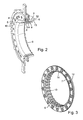
Figur 1 vorhandenen Steckverbindung, - Figur 3
- ein die Steckverbindung bildendes Bauteil.
- In
Figur 1 ist eine Antriebsverbindung 1 erkennbar, die als axiale Steckverbindung 1a ausgebildet ist. Über diese axiale Steckverbindung 1a sind zwei Untereinheiten 2 und 3 miteinander verbindbar, von denen die Untereinheit 2 einen Dämpfer umfasst, der mit der Abtriebswelle einer Brennkraftmaschine verbindbar ist, und die Untereinheit 3 zum Beispiel eine Doppelkupplung beinhaltet, die getriebeseitig vormontierbar ist. Derartige Doppelkupplungen sind durch den eingangs genannten Stand der Technik bekannt. - Die axiale Steckverbindung 1 a ist, wie in Zusammenhang mit
Figur 2 erkennbar, durch eine Verzahnungsverbindung 4 gebildet, welche Verzahnungsprofile 5 und 6 aufweist, die ineinander greifen. InFigur 2 sind die Verzahnungsprofile 5 und 6 in einer relativen Position gezeigt, in der diese Verzahnungsprofile 5, 6 lediglich teilweise axial aufeinander geschoben sind. - Die Verzahnungsprofile 5 sind bei dem dargestellten Ausführungsbeispiel von einem flanschartigen Ausgangsteil 10 des Dämpfers 2 getragen, und die Verzahnungsprofile 6 von einem Mitnehmerring, der Bestandteil der getriebeseitig vormontierten Untereinheit 3 ist. Die Verzahnungsprofile 6 bilden eine Innenverzahnung, wohingegen die Verzahnungsprofile 5 eine entsprechend angepasste Außenverzahnung bilden. Bei dem dargestellten Ausführungsbeispiel werden die Verzahnungsprofile 5 von einem axialen Ansatz 8 des Ausgangsteils 10 getragen. Der axiale Ansatz 8 ist hier ringartig ausgebildet und axial in Richtung der Untereinheit 3 ausgerichtet. Die Verzahnungsprofile 5 können unmittelbar dem axialen Ansatz 8 angeformt sein oder aber, wie bei dem dargestellten Ausführungsbeispiel, durch ein separates Bauteil 9 gebildet sein, das fest mit dem axialen Ansatz 8 bzw. dem Ausgangsteil 10 verbunden ist. In vorteilhafter Weise kann das Bauteil 9 als Blechformteil ausgebildet und zumindest oberflächengehärtet sein. Die Bauteile 7 und 10 sind bei dem dargestellten Ausführungsbeispiel ebenfalls als Blechteile ausgebildet. Aus
Figur 1 ist erkennbar, dass der Mitnehmerring 7 mit einem ringförmigen Mitnehmerbauteil 11 vernietet ist. Diese Vernietung kann mittels separater Nietelemente, wie dargestellt, erfolgen, oder es können aus zumindest einem der Bauteile 7 und 11 einstückige Nietwarzen herausgebildet werden, mittels derer die entsprechenden Nietverbindungen hergestellt werden können. Die Teile können auch verschweißt werden. - Das Mitnehmerbauteil 11 bildet einen Bestandteil der getriebeseitig vormontierbaren Untereinheit 3.
- Der Mitnehmerring 7 ist als ringförmiges, im Querschnitt winkelförmiges Bauteil ausgebildet, wobei der axial hülsenförmige Bereich 12 hier unmittelbar die Verzahnungsprofile 6 bildet. Es könnte jedoch, ähnlich wie dies in Zusammenhang mit den Verzahnungsprofilen 5 beschrieben wurde, ein separates Bauteil verwendet werden.
- Bei dem dargestellten Ausführungsbeispiel sind die Verzahnungsprofile 6 des Mitnehmerringes 7 mit einem dämpfenden Material 13 beschichtet. Dabei kann es zweckmäßig sein, wenn alle Verzahnungsprofile 6 eine entsprechende Beschichtung aufweisen. Für manche Anwendungsfälle kann es jedoch auch zweckmäßig sein, wenn lediglich einzelne, über den Umfang verteilte Verzahnungsprofile 6 eine derartige Beschichtung besitzen, wobei diese dann eine andere Form bzw. Teilung besitzen können als die übrigen Verzahnungsprofile 6 ohne Beschichtung. Bei einer derartigen Ausgestaltung kann es gar zweckmäßig sein, wenn die ineinander greifenden Verzahnungsprofile 5 und 6 ohne dämpfende Zwischenschicht zumindest ein geringes Verdrehspiel, zum Beispiel in der Größenordnung von 0,2 bis 0,5 Winkelgrad aufweisen. Für manche Anwendungsfälle kann es auch vorteilhaft sein, wenn dieser Verdrehwinkel größer ist oder aber praktisch kein Verdrehwinkel zwischen den ineinander greifenden Verzahnungsprofilen vorhanden ist.
- Bei dem dargestellten Ausführungsbeispiel sind sowohl die Flanken als auch der Kopfbereich sowie der Fußbereich der Verzahnungsprofile 6 beschichtet. Es kann jedoch auch zweckmä-βig sein, lediglich die Flanken der Verzahnungsprofile 6 und gegebenenfalls den Fußbereich und/oder den Kopfbereich dieser Verzahnungsprofile 6 mit einem dämpfenden Material zu beschichten. Die Beschichtung der Verzahnungsprofile 6 kann in vorteilhafter Weise derart erfolgen, dass zwischen den Fußbereichen und/oder den Kopfbereichen der Verzahnungsprofile 5 und den diesen radial gegenüber liegenden, durch die Materialbeschichtung 13 gebildeten Kopfbereichen und/oder Fußbereichen der Verzahnungsprofile 6 zumindest ein geringes radiales Spiel verbleibt. In vorteilhafter Weise kann die Dicke der dämpfenden Materialbeschichtung 13 in Bezug auf die Verzahnungsprofile 5 derart abgestimmt sein, dass beim Aufeinanderschieben der beiden Verzahnungsprofile 5 und 6 zumindest eine geringe Verformung des Materials 13 auftritt. Für manche Anwendungsfälle kann es jedoch auch zweckmäßig sein, wenn ein geringes Spiel zwischen den einander zugeordneten Verzahnungsprofilen 5 und 6 vorgesehen wird, wodurch die Montage erleichtert wird. Um die Montage zu begünstigen, ist es besonders vorteilhaft, wenn vor dem Aufeinanderschieben der beiden Bauteile 10 und 7 bzw. der Verzahnungsprofile 5 und 6 zumindest die Oberfläche der Verzahnungsprofile 5 und/oder 6 mit einem Gleitwerkstoff, wie zum Beispiel Fett, Öl, Graphitpartikeln oder ähnlichem, beschichtet sind. Dadurch kann die Montage bzw. das Aufeinanderschieben der Verzahnungsprofile 5 und 6 wesentlich erleichtert werden und darüber hinaus auch eine Beschädigung der Materialbeschichtung 13 verhindert werden.
- Aus
Figur 2 ist ersichtlich, dass das Bauteil 7 derart ausgebildet ist, dass das dämpfende Material 13 eine die Montage erleichternde Einführkontur bzw. Positionskontur 14 bildet. Diese Kontur bildet auch einen axialen Anschlag zwischen den Bauteilen 7 und 10. - In besonders vorteilhafter Weise kann das die Beschichtung 13 bildende Material zumindest eine gewisse Eigenelastizität, also federnde Verformbarkeit, aufweisen. Diese Eigenelastizität bzw. Verformbarkeit gewährleistet eine Dämpfung der zwischen den beiden Bauteilen 10 und 7 auftretenden Drehschwingungen bzw. Drehmomentschwankungen. In vorteilhafter Weise kann das die Beschichtung 13 bildende Material zumindest aus einem Kunststoff bestehen, der, falls erforderlich, mit einem Gleitmaterial, wie zum Beispiel Polytetrafluoräthylen (PTFE), beschichtet sein kann. Der Kunststoff soll dabei, wie bereits angedeutet, zumindest eine gewisse Eigenelastizität bzw. Verformbarkeit besitzen. Besonders zweckmäßig kann es sein, wenn das die Beschichtung 13 bildende Material zumindest teilweise durch einen Elastomer, wie Gummi, gebildet ist. Der Gummi bzw. der Kunststoff soll vorzugsweise hochtemperaturbeständig sein, also Temperaturen von zumindest 100° C über längere Zeit widerstehen.
- Die Schichtdicke der Beschichtung 13 kann in der Größenordnung von 0,3 bis 1,5 mm liegen. Für die meisten Anwendungsfälle ist es zweckmäßig, wenn diese Beschichtungsdicke in der Größenordnung von 0,8 bis 1,2 mm liegt, beispielsweise 1 mm beträgt. Zweckmäßig kann es auch sein, wenn die Schichtdicke über die umfangsmäßige Erstreckung der Verzahnungsprofile 6 unterschiedlich ist. So kann beispielsweise die Schichtdicke im Bereich der Flanken der Verzahnungsprofile 6 größer sein als im Bereich des Kopf- und/oder Fußdurchmessers dieser Verzahnungsprofile 6. Für manche Anwendungsfälle kann es auch zweckmäßig sein, wenn diese Verhältnisse umgekehrt sind.
- Das die Beschichtung 13 bildende Material kann auf das entsprechende Bauteil, das hier durch den Mitnehmerring 7 gebildet ist, aufvulkanisiert sein. Für manche Anwendungsfälle kann es jedoch auch zweckmäßig sein, wenn das die Beschichtung 13 bildende Material ein separates Bauteil bildet, das entweder lose zwischengelegt wird bei der Montage, oder aber mit dem entsprechenden Bauteil, hier mit dem Mitnehmerring 7 fest verbunden wird. Letzteres kann beispielsweise mittels einer zumindest partiellen Verklebung und/oder durch entsprechende Ausgestaltung der Bauteile, welche eine formschlüssige Verbindung zwischen den zu verbindenden Bauteilen gewährleisten, erfolgen.
- Bei dem dargestellten Ausführungsbeispiel ist das eine Beschichtung 13 bildende, dämpfende Material auf den Verzahnungsprofilen 6 vorgesehen. Es kann jedoch auch zweckmäßig sein, dieses dämpfende Material auf den Verzahnungsprofilen 5 oder gar sowohl auf den Verzahnungsprofilen 6 als auch auf den Verzahnungsprofilen 5 vorzusehen. Dabei können alle Verzahnungsprofile 6 und/oder alle Verzahnungsprofile 5 beschichtet sein oder aber lediglich einzelne, über den Umfang verteilte Verzahnungsprofile 5 und/oder 6. Die Verzahnungsprofile 5 und/oder 6 können jedoch auch gruppenweise über den Umfang verteilt mit einer entsprechenden Beschichtung 13 versehen werden. Auch kann es zweckmäßig sein, beschichtete Verzahnungsprofile 6 und beschichtete Verzahnungsprofile 5 über den Umfang verteilt vorzusehen, wobei die beschichteten Verzahnungsprofile 6 gegenüber den beschichteten Verzahnungsprofilen 5 umfangsmäßig zueinander versetzt angeordnet werden können.
- Die Ausführungsbeispiele sind nicht als Einschränkung der Erfindung zu verstehen. Vielmehr sind im Rahmen der vorliegenden Offenbarung zahlreiche Abänderungen und Modifikationen möglich, insbesondere solche, die durch Kombination oder Abwandlung von einzelnen in Verbindung mit den in der allgemeinen Beschreibung und der Figurenbeschreibung sowie den Ansprüchen beschriebenen und in den Zeichnungen enthaltenen Merkmalen bzw. Elementen oder Verfahrensschritten gebildet werden können.
-
- 1
- Antriebsverbindung
- 1 a
- Steckverbindung
- 2
- Untereinheit
- 3
- Untereinheit
- 4
- Verzahnungsverbindung
- 5
- Verzahnungsprofile
- 6
- Verzahnungsprofile
- 7
- Bauteil
- 8
- Axialer Ansatz
- 9
- Bauteil
- 10
- Bauteil
- 11
- Bauteil
- 12
- Hülsenförmiger Bereich
- 13
- Dämpfendes Material
- 14
- Einführkontur
Claims (10)
- Kupplungsaggregat, das aus wenigstens zwei Untereinheiten besteht, wobei die eine Untereinheit mit der Abtriebswelle eines Motors verbindbar und die andere Untereinheit getriebeseitig vormontierbar ist und beide Untereinheiten über eine axiale Steckverbindung, die ineinander greifende Profilierungen und Gegenprofilierungen umfasst, miteinander koppelbar sind, dadurch gekennzeichnet, dass zumindest einzelne der die Profilierungen (5) und/oder Gegenprofilierungen (6) bildenden, zahnförmigen Profile mit einem dämpfenden Material (13) beschichtet sind.
- Kupplungsaggregat nach Anspruch 1, dadurch gekennzeichnet, dass das dämpfende Material (13) zumindest aus einem Kunststoff besteht.
- Kupplungsaggregat nach Anspruch 1 oder 2, dadurch gekennzeichnet, dass das dämpfende Material (13) zumindest durch einen Elastomer gebildet ist.
- Kupplungsaggregat nach einem der Ansprüche 1 bis 3, dadurch gekennzeichnet, dass das dämpfende Material (13) aus einem hochtemperaturbeständigen Kunststoff gebildet ist.
- Kupplungsaggregat nach einem der Ansprüche 1 bis 4, dadurch gekennzeichnet, dass die Schichtdicke des zumindest auf einzelne zahnförmige Profile (5, 6) aufgebrachte dämpfende Material (13) in der Größenordnung von 0,3 bis 1,5 mm, vorzugsweise in der Größenordnung von 0,8 bis 1,2 mm liegt.
- Kupplungsaggregat nach einem der Ansprüche 1 bis 5, dadurch gekennzeichnet, dass die gesamten Profilierungen (5) und/oder die gesamten Gegenprofilierungen (6) beschichtet sind.
- Kupplungsaggregat nach einem der Ansprüche 1 bis 6, dadurch gekennzeichnet, dass lediglich die Zahnflanken von zahnförmigen Profilen (5, 6) beschichtet sind.
- Kupplungsaggregat nach einem der Ansprüche 1 bis 7, dadurch gekennzeichnet, dass das dämpfende Material (13) auf die entsprechenden zahnförmigen Profile aufvulkanisiert ist.
- Kupplungsaggregat nach einem der Ansprüche 1 bis 8, dadurch gekennzeichnet, dass die Oberfläche des dämpfenden Materials (13) zumindest partiell mit einem Gleitmittel versehen ist.
- Kupplungsaggregat nach Anspruch 1 bis 9, dadurch gekennzeichnet, dass alle zahnförmigen Profile der Profilierungen (5) und/oder Gegenprofilierungen (6) zumindest partiell mit einem dämpfenden Material beschichtet sind.
Applications Claiming Priority (1)
| Application Number | Priority Date | Filing Date | Title |
|---|---|---|---|
| DE102007030721 | 2007-07-02 |
Publications (2)
| Publication Number | Publication Date |
|---|---|
| EP2012034A2 true EP2012034A2 (de) | 2009-01-07 |
| EP2012034A3 EP2012034A3 (de) | 2010-10-20 |
Family
ID=39791390
Family Applications (1)
| Application Number | Title | Priority Date | Filing Date |
|---|---|---|---|
| EP08010444A Withdrawn EP2012034A3 (de) | 2007-07-02 | 2008-06-09 | Kupplungsaggregat |
Country Status (3)
| Country | Link |
|---|---|
| EP (1) | EP2012034A3 (de) |
| CN (1) | CN101338795A (de) |
| DE (1) | DE102008027443A1 (de) |
Families Citing this family (6)
| Publication number | Priority date | Publication date | Assignee | Title |
|---|---|---|---|---|
| DE102010006472A1 (de) | 2009-02-13 | 2010-08-26 | Luk Lamellen Und Kupplungsbau Beteiligungs Kg | Drehmomentübertragungseinrichtung |
| DE102010050462B4 (de) | 2009-11-09 | 2024-10-10 | Schaeffler Technologies AG & Co. KG | Steckverzahnung in einem Kupplungsaggregat |
| EP2516872B1 (de) | 2009-12-21 | 2015-04-08 | Schaeffler Technologies AG & Co. KG | Vorrichtung mit einer steckverbindung |
| DE102010021057A1 (de) * | 2010-05-19 | 2011-11-24 | Gm Global Technology Operations Llc (N.D.Ges.D. Staates Delaware) | Synchronisiervorrichtung eines Wechselschaltgetriebes |
| DE102012206678A1 (de) | 2011-05-11 | 2012-11-15 | Schaeffler Technologies AG & Co. KG | Steckverbindung zur drehschlüssigen Verbindung zweier Bauteile und Verfahren |
| CN103547824A (zh) | 2011-06-22 | 2014-01-29 | 舍弗勒技术股份两合公司 | 转矩传递装置 |
Citations (3)
| Publication number | Priority date | Publication date | Assignee | Title |
|---|---|---|---|---|
| DE102005027608A1 (de) | 2004-06-21 | 2005-12-29 | Luk Lamellen Und Kupplungsbau Beteiligungs Kg | Drehmomentübertragungseinrichtungssystem |
| DE102005037514A1 (de) | 2004-09-03 | 2006-03-09 | Luk Lamellen Und Kupplungsbau Beteiligungs Kg | Drehmomentübertragungseinrichtung |
| WO2007000151A2 (de) | 2005-06-28 | 2007-01-04 | Luk Lamellen Und Kupplungsbau Beteiligungs Kg | Kupplungsaggregat |
Family Cites Families (5)
| Publication number | Priority date | Publication date | Assignee | Title |
|---|---|---|---|---|
| GB763157A (en) * | 1953-12-14 | 1956-12-12 | Huttenwerke Ilsede Peine Ag | Improvements in or relating to gear couplings |
| DE3822637A1 (de) * | 1988-07-05 | 1990-01-18 | Daimler Benz Ag | Elastische verdrehsichere wellen-nabenverbindung |
| DE19515103C2 (de) * | 1995-04-25 | 1997-07-03 | Freudenberg Carl Fa | Vielkeilwellenverbindung |
| FR2737266B1 (fr) * | 1995-07-26 | 1997-10-31 | Journee Paul | Friction d'embrayage et embrayage equipe d'une telle friction |
| DE19939527A1 (de) * | 1999-08-20 | 2001-03-08 | Bayerische Motoren Werke Ag | Drehmomentwandleranbindung |
-
2008
- 2008-06-09 EP EP08010444A patent/EP2012034A3/de not_active Withdrawn
- 2008-06-09 DE DE102008027443A patent/DE102008027443A1/de not_active Withdrawn
- 2008-07-02 CN CNA2008101295866A patent/CN101338795A/zh active Pending
Patent Citations (3)
| Publication number | Priority date | Publication date | Assignee | Title |
|---|---|---|---|---|
| DE102005027608A1 (de) | 2004-06-21 | 2005-12-29 | Luk Lamellen Und Kupplungsbau Beteiligungs Kg | Drehmomentübertragungseinrichtungssystem |
| DE102005037514A1 (de) | 2004-09-03 | 2006-03-09 | Luk Lamellen Und Kupplungsbau Beteiligungs Kg | Drehmomentübertragungseinrichtung |
| WO2007000151A2 (de) | 2005-06-28 | 2007-01-04 | Luk Lamellen Und Kupplungsbau Beteiligungs Kg | Kupplungsaggregat |
Also Published As
| Publication number | Publication date |
|---|---|
| DE102008027443A1 (de) | 2009-01-08 |
| CN101338795A (zh) | 2009-01-07 |
| EP2012034A3 (de) | 2010-10-20 |
Similar Documents
| Publication | Publication Date | Title |
|---|---|---|
| EP1902226B1 (de) | Kupplungsaggregat | |
| DE10133693B4 (de) | Torsionsschwingungsdämpfer | |
| EP1988306B1 (de) | Kupplungsscheibe | |
| WO2007000131A2 (de) | Kupplungssystem | |
| DE102015225008A1 (de) | Drehmomentübertragungseinrichtung mit Steckverbindung | |
| EP2012034A2 (de) | Kupplungsaggregat | |
| DE10022846A1 (de) | Getriebe | |
| DE102011102910A1 (de) | Drehmomentübertragungsvorrichtung | |
| DE102013217775A1 (de) | Drehschwingungsdämpfer und Reibring hierfür | |
| DE102010051906A1 (de) | Drehschwingungsdämpfer | |
| EP1774196B1 (de) | Vorrichtung zur übertragung eines drehmoments | |
| DE102018110076A1 (de) | Welle-Nabe-Verbindung, insbesondere für einen Drehschwingungsdämpfer und Drehschwingungsdämpfer mit einem Nabenteil dieser | |
| EP1957817A1 (de) | Drehmomentübertragungseinrichtung | |
| DE102014226430B4 (de) | Verbindungselement für eine Welle-Nabe Verbindung mit einer Welle | |
| DE102014208273A1 (de) | Verbindungselement für eine Welle-Nabe-Verbindung, insbesondere zur Drehmomentübertragung in einem Antriebsstrang eines Kraftfahrzeugs, sowie Verwendung eines derartigen Verbindungselements | |
| DE102009042071A1 (de) | Kraftübertragungseinrichtung | |
| DE102019129063A1 (de) | Verbindungselement für eine Welle-Nabe-Verbindung, insbesondere zur Drehmomentübertragung in einem Antriebsstrang eines Kraftfahrzeugs | |
| DE102014216041A1 (de) | Drehschwingungsdämpfer und Verfahren zu dessen Montage in einem Antriebsstrang zwischen einer Brennkraftmaschine und einem Getriebe | |
| DE102022114887A1 (de) | Drehschwingungsdämpfer und ein Verfahren zu dessen Montage | |
| DE102010006472A1 (de) | Drehmomentübertragungseinrichtung | |
| DE102019113443B4 (de) | Riemenscheibenentkoppler mit beidseitiger Axialverzahnung sowie Nebenaggregattrieb | |
| DE102011100874A1 (de) | Ausgleichselement für eine Welle-Nabe-Verbindung | |
| DE102017119495A1 (de) | Drehschwingungsdämpfer und Verfahren zur Herstellung eines Drehschwingungsdämpfers | |
| DE102015109872A1 (de) | Welle-Nabe-Verbindung und Drehmomentübertragungseinrichtung mit mindestens einer Welle-Nabe-Verbindung | |
| DE102020127561A1 (de) | Drehschwingungsdämpfer |
Legal Events
| Date | Code | Title | Description |
|---|---|---|---|
| PUAI | Public reference made under article 153(3) epc to a published international application that has entered the european phase |
Free format text: ORIGINAL CODE: 0009012 |
|
| AK | Designated contracting states |
Kind code of ref document: A2 Designated state(s): AT BE BG CH CY CZ DE DK EE ES FI FR GB GR HR HU IE IS IT LI LT LU LV MC MT NL NO PL PT RO SE SI SK TR |
|
| AX | Request for extension of the european patent |
Extension state: AL BA MK RS |
|
| PUAL | Search report despatched |
Free format text: ORIGINAL CODE: 0009013 |
|
| AK | Designated contracting states |
Kind code of ref document: A3 Designated state(s): AT BE BG CH CY CZ DE DK EE ES FI FR GB GR HR HU IE IS IT LI LT LU LV MC MT NL NO PL PT RO SE SI SK TR |
|
| AX | Request for extension of the european patent |
Extension state: AL BA MK RS |
|
| RIC1 | Information provided on ipc code assigned before grant |
Ipc: F16D 3/68 20060101ALI20100915BHEP Ipc: F16D 1/10 20060101AFI20081009BHEP |
|
| REG | Reference to a national code |
Ref country code: DE Ref legal event code: R108 |
|
| AKY | No designation fees paid | ||
| REG | Reference to a national code |
Ref country code: DE Ref legal event code: R108 Effective date: 20110623 |
|
| STAA | Information on the status of an ep patent application or granted ep patent |
Free format text: STATUS: THE APPLICATION IS DEEMED TO BE WITHDRAWN |
|
| 18D | Application deemed to be withdrawn |
Effective date: 20110421 |
|
| P01 | Opt-out of the competence of the unified patent court (upc) registered |
Effective date: 20230522 |