EP2011604A1 - Verfahren zum Festhalten eines Linsenrohlings, Haftmittelzusammensetzung und deren Verwendung beim Festhalten von Linsen - Google Patents
Verfahren zum Festhalten eines Linsenrohlings, Haftmittelzusammensetzung und deren Verwendung beim Festhalten von Linsen Download PDFInfo
- Publication number
- EP2011604A1 EP2011604A1 EP07013158A EP07013158A EP2011604A1 EP 2011604 A1 EP2011604 A1 EP 2011604A1 EP 07013158 A EP07013158 A EP 07013158A EP 07013158 A EP07013158 A EP 07013158A EP 2011604 A1 EP2011604 A1 EP 2011604A1
- Authority
- EP
- European Patent Office
- Prior art keywords
- lens
- adhesive composition
- blocking
- block
- filler
- Prior art date
- Legal status (The legal status is an assumption and is not a legal conclusion. Google has not performed a legal analysis and makes no representation as to the accuracy of the status listed.)
- Granted
Links
- 230000001070 adhesive effect Effects 0.000 title claims abstract description 158
- 239000000853 adhesive Substances 0.000 title claims abstract description 157
- 230000000903 blocking effect Effects 0.000 title claims abstract description 130
- 239000000203 mixture Substances 0.000 title claims abstract description 113
- 238000000034 method Methods 0.000 title claims abstract description 61
- 239000000463 material Substances 0.000 claims abstract description 133
- 239000000945 filler Substances 0.000 claims abstract description 84
- 239000007787 solid Substances 0.000 claims abstract description 30
- 230000000379 polymerizing effect Effects 0.000 claims abstract description 20
- 238000006116 polymerization reaction Methods 0.000 claims abstract description 17
- 239000002245 particle Substances 0.000 claims description 33
- 239000007788 liquid Substances 0.000 claims description 32
- 238000002156 mixing Methods 0.000 claims description 25
- 229920005989 resin Polymers 0.000 claims description 15
- 239000011347 resin Substances 0.000 claims description 15
- SOGAXMICEFXMKE-UHFFFAOYSA-N Butylmethacrylate Chemical compound CCCCOC(=O)C(C)=C SOGAXMICEFXMKE-UHFFFAOYSA-N 0.000 claims description 12
- 230000008859 change Effects 0.000 claims description 11
- 239000000835 fiber Substances 0.000 claims description 11
- PAPBSGBWRJIAAV-UHFFFAOYSA-N ε-Caprolactone Chemical compound O=C1CCCCCO1 PAPBSGBWRJIAAV-UHFFFAOYSA-N 0.000 claims description 11
- 238000009826 distribution Methods 0.000 claims description 7
- 230000000694 effects Effects 0.000 claims description 7
- CERQOIWHTDAKMF-UHFFFAOYSA-M Methacrylate Chemical compound CC(=C)C([O-])=O CERQOIWHTDAKMF-UHFFFAOYSA-M 0.000 claims description 6
- 238000010521 absorption reaction Methods 0.000 claims description 6
- 239000008187 granular material Substances 0.000 claims description 6
- 239000004698 Polyethylene Substances 0.000 claims description 5
- 229910052782 aluminium Inorganic materials 0.000 claims description 5
- XAGFODPZIPBFFR-UHFFFAOYSA-N aluminium Chemical compound [Al] XAGFODPZIPBFFR-UHFFFAOYSA-N 0.000 claims description 5
- 229920006026 co-polymeric resin Polymers 0.000 claims description 5
- 229920000573 polyethylene Polymers 0.000 claims description 5
- 125000002496 methyl group Chemical group [H]C([H])([H])* 0.000 claims description 4
- 229920000515 polycarbonate Polymers 0.000 claims description 4
- 239000004417 polycarbonate Substances 0.000 claims description 4
- 229920001897 terpolymer Polymers 0.000 claims description 4
- KIQNOXFYOCZBMH-UHFFFAOYSA-N 2-methylpent-2-enoic acid prop-2-enoic acid Chemical compound C(C=C)(=O)O.C(C)C=C(C(=O)O)C KIQNOXFYOCZBMH-UHFFFAOYSA-N 0.000 claims description 3
- SUPCQIBBMFXVTL-UHFFFAOYSA-N ethyl 2-methylprop-2-enoate Chemical compound CCOC(=O)C(C)=C SUPCQIBBMFXVTL-UHFFFAOYSA-N 0.000 claims description 3
- 230000009477 glass transition Effects 0.000 claims description 3
- 229910052751 metal Inorganic materials 0.000 claims description 3
- 239000002184 metal Substances 0.000 claims description 3
- 239000000843 powder Substances 0.000 claims description 3
- -1 Polyethylene Polymers 0.000 claims description 2
- BAPJBEWLBFYGME-UHFFFAOYSA-N acrylic acid methyl ester Natural products COC(=O)C=C BAPJBEWLBFYGME-UHFFFAOYSA-N 0.000 claims description 2
- 239000004033 plastic Substances 0.000 claims description 2
- 229920003023 plastic Polymers 0.000 claims description 2
- 230000005855 radiation Effects 0.000 abstract description 12
- 239000002861 polymer material Substances 0.000 abstract description 3
- 230000008569 process Effects 0.000 description 22
- 230000008901 benefit Effects 0.000 description 15
- 150000001875 compounds Chemical class 0.000 description 12
- 238000012545 processing Methods 0.000 description 10
- 230000009467 reduction Effects 0.000 description 10
- 238000010438 heat treatment Methods 0.000 description 9
- 230000035882 stress Effects 0.000 description 9
- 238000003754 machining Methods 0.000 description 8
- 230000001788 irregular Effects 0.000 description 7
- 238000013459 approach Methods 0.000 description 6
- 238000000227 grinding Methods 0.000 description 6
- 238000003384 imaging method Methods 0.000 description 6
- 238000004519 manufacturing process Methods 0.000 description 6
- 230000001965 increasing effect Effects 0.000 description 5
- 238000005086 pumping Methods 0.000 description 5
- 238000006243 chemical reaction Methods 0.000 description 4
- 238000005520 cutting process Methods 0.000 description 4
- 238000005516 engineering process Methods 0.000 description 4
- 230000002829 reductive effect Effects 0.000 description 4
- 239000002904 solvent Substances 0.000 description 4
- 239000000126 substance Substances 0.000 description 4
- NIXOWILDQLNWCW-UHFFFAOYSA-M Acrylate Chemical compound [O-]C(=O)C=C NIXOWILDQLNWCW-UHFFFAOYSA-M 0.000 description 3
- FAIIFDPAEUKBEP-UHFFFAOYSA-N Nilvadipine Chemical compound COC(=O)C1=C(C#N)NC(C)=C(C(=O)OC(C)C)C1C1=CC=CC([N+]([O-])=O)=C1 FAIIFDPAEUKBEP-UHFFFAOYSA-N 0.000 description 3
- 239000007767 bonding agent Substances 0.000 description 3
- 238000000576 coating method Methods 0.000 description 3
- 230000005670 electromagnetic radiation Effects 0.000 description 3
- 230000006698 induction Effects 0.000 description 3
- 239000011159 matrix material Substances 0.000 description 3
- 238000010943 off-gassing Methods 0.000 description 3
- 230000003287 optical effect Effects 0.000 description 3
- 238000005498 polishing Methods 0.000 description 3
- 239000000047 product Substances 0.000 description 3
- 238000001429 visible spectrum Methods 0.000 description 3
- 229920005479 Lucite® Polymers 0.000 description 2
- 239000011324 bead Substances 0.000 description 2
- 239000011248 coating agent Substances 0.000 description 2
- 229920001577 copolymer Polymers 0.000 description 2
- 238000013461 design Methods 0.000 description 2
- 238000011161 development Methods 0.000 description 2
- 230000018109 developmental process Effects 0.000 description 2
- 230000007613 environmental effect Effects 0.000 description 2
- 238000009501 film coating Methods 0.000 description 2
- 230000004927 fusion Effects 0.000 description 2
- 229910001092 metal group alloy Inorganic materials 0.000 description 2
- 239000012768 molten material Substances 0.000 description 2
- 239000000178 monomer Substances 0.000 description 2
- 229920001610 polycaprolactone Polymers 0.000 description 2
- 239000004632 polycaprolactone Substances 0.000 description 2
- 229920000642 polymer Polymers 0.000 description 2
- 239000004926 polymethyl methacrylate Substances 0.000 description 2
- 230000001681 protective effect Effects 0.000 description 2
- 238000004064 recycling Methods 0.000 description 2
- 229920001169 thermoplastic Polymers 0.000 description 2
- 239000004416 thermosoftening plastic Substances 0.000 description 2
- 239000010409 thin film Substances 0.000 description 2
- 238000002211 ultraviolet spectrum Methods 0.000 description 2
- 239000012855 volatile organic compound Substances 0.000 description 2
- XLYOFNOQVPJJNP-UHFFFAOYSA-N water Substances O XLYOFNOQVPJJNP-UHFFFAOYSA-N 0.000 description 2
- OKTJSMMVPCPJKN-UHFFFAOYSA-N Carbon Chemical compound [C] OKTJSMMVPCPJKN-UHFFFAOYSA-N 0.000 description 1
- 230000004913 activation Effects 0.000 description 1
- 230000009286 beneficial effect Effects 0.000 description 1
- XMQFTWRPUQYINF-UHFFFAOYSA-N bensulfuron-methyl Chemical compound COC(=O)C1=CC=CC=C1CS(=O)(=O)NC(=O)NC1=NC(OC)=CC(OC)=N1 XMQFTWRPUQYINF-UHFFFAOYSA-N 0.000 description 1
- 230000005540 biological transmission Effects 0.000 description 1
- 229910052799 carbon Inorganic materials 0.000 description 1
- 238000004140 cleaning Methods 0.000 description 1
- 230000001427 coherent effect Effects 0.000 description 1
- 230000002301 combined effect Effects 0.000 description 1
- 239000004020 conductor Substances 0.000 description 1
- 238000011109 contamination Methods 0.000 description 1
- 238000007796 conventional method Methods 0.000 description 1
- 230000008878 coupling Effects 0.000 description 1
- 238000010168 coupling process Methods 0.000 description 1
- 238000005859 coupling reaction Methods 0.000 description 1
- 230000003247 decreasing effect Effects 0.000 description 1
- 230000001419 dependent effect Effects 0.000 description 1
- 230000001066 destructive effect Effects 0.000 description 1
- 238000010586 diagram Methods 0.000 description 1
- 229910003460 diamond Inorganic materials 0.000 description 1
- 239000010432 diamond Substances 0.000 description 1
- 238000007516 diamond turning Methods 0.000 description 1
- 230000002708 enhancing effect Effects 0.000 description 1
- 239000010408 film Substances 0.000 description 1
- 239000012530 fluid Substances 0.000 description 1
- 239000011521 glass Substances 0.000 description 1
- 230000020169 heat generation Effects 0.000 description 1
- 238000007654 immersion Methods 0.000 description 1
- 230000002401 inhibitory effect Effects 0.000 description 1
- 229910052500 inorganic mineral Inorganic materials 0.000 description 1
- 239000004922 lacquer Substances 0.000 description 1
- 238000005259 measurement Methods 0.000 description 1
- 230000007246 mechanism Effects 0.000 description 1
- 238000002844 melting Methods 0.000 description 1
- 239000002923 metal particle Substances 0.000 description 1
- 238000003801 milling Methods 0.000 description 1
- 239000011707 mineral Substances 0.000 description 1
- 238000012544 monitoring process Methods 0.000 description 1
- 239000003973 paint Substances 0.000 description 1
- 230000036961 partial effect Effects 0.000 description 1
- 239000008188 pellet Substances 0.000 description 1
- 238000007781 pre-processing Methods 0.000 description 1
- 238000003908 quality control method Methods 0.000 description 1
- 238000007670 refining Methods 0.000 description 1
- 239000011265 semifinished product Substances 0.000 description 1
- 238000012360 testing method Methods 0.000 description 1
- 230000008646 thermal stress Effects 0.000 description 1
- 239000012780 transparent material Substances 0.000 description 1
- 238000007514 turning Methods 0.000 description 1
- 229910000634 wood's metal Inorganic materials 0.000 description 1
- 229910052724 xenon Inorganic materials 0.000 description 1
- FHNFHKCVQCLJFQ-UHFFFAOYSA-N xenon atom Chemical compound [Xe] FHNFHKCVQCLJFQ-UHFFFAOYSA-N 0.000 description 1
Images


Classifications
-
- B—PERFORMING OPERATIONS; TRANSPORTING
- B24—GRINDING; POLISHING
- B24B—MACHINES, DEVICES, OR PROCESSES FOR GRINDING OR POLISHING; DRESSING OR CONDITIONING OF ABRADING SURFACES; FEEDING OF GRINDING, POLISHING, OR LAPPING AGENTS
- B24B13/00—Machines or devices designed for grinding or polishing optical surfaces on lenses or surfaces of similar shape on other work; Accessories therefor
- B24B13/005—Blocking means, chucks or the like; Alignment devices
- B24B13/0057—Deblocking of lenses
-
- B—PERFORMING OPERATIONS; TRANSPORTING
- B29—WORKING OF PLASTICS; WORKING OF SUBSTANCES IN A PLASTIC STATE IN GENERAL
- B29D—PRODUCING PARTICULAR ARTICLES FROM PLASTICS OR FROM SUBSTANCES IN A PLASTIC STATE
- B29D11/00—Producing optical elements, e.g. lenses or prisms
- B29D11/00009—Production of simple or compound lenses
- B29D11/00423—Plants for the production of simple or compound lenses
-
- B—PERFORMING OPERATIONS; TRANSPORTING
- B29—WORKING OF PLASTICS; WORKING OF SUBSTANCES IN A PLASTIC STATE IN GENERAL
- B29D—PRODUCING PARTICULAR ARTICLES FROM PLASTICS OR FROM SUBSTANCES IN A PLASTIC STATE
- B29D11/00—Producing optical elements, e.g. lenses or prisms
- B29D11/00932—Combined cutting and grinding thereof
- B29D11/00942—Combined cutting and grinding thereof where the lens material is mounted in a support for mounting onto a cutting device, e.g. a lathe, and where the support is of machinable material, e.g. plastics
-
- C—CHEMISTRY; METALLURGY
- C09—DYES; PAINTS; POLISHES; NATURAL RESINS; ADHESIVES; COMPOSITIONS NOT OTHERWISE PROVIDED FOR; APPLICATIONS OF MATERIALS NOT OTHERWISE PROVIDED FOR
- C09J—ADHESIVES; NON-MECHANICAL ASPECTS OF ADHESIVE PROCESSES IN GENERAL; ADHESIVE PROCESSES NOT PROVIDED FOR ELSEWHERE; USE OF MATERIALS AS ADHESIVES
- C09J133/00—Adhesives based on homopolymers or copolymers of compounds having one or more unsaturated aliphatic radicals, each having only one carbon-to-carbon double bond, and at least one being terminated by only one carboxyl radical, or of salts, anhydrides, esters, amides, imides, or nitriles thereof; Adhesives based on derivatives of such polymers
- C09J133/04—Homopolymers or copolymers of esters
- C09J133/06—Homopolymers or copolymers of esters of esters containing only carbon, hydrogen and oxygen, the oxygen atom being present only as part of the carboxyl radical
- C09J133/10—Homopolymers or copolymers of methacrylic acid esters
- C09J133/12—Homopolymers or copolymers of methyl methacrylate
-
- C—CHEMISTRY; METALLURGY
- C08—ORGANIC MACROMOLECULAR COMPOUNDS; THEIR PREPARATION OR CHEMICAL WORKING-UP; COMPOSITIONS BASED THEREON
- C08L—COMPOSITIONS OF MACROMOLECULAR COMPOUNDS
- C08L2666/00—Composition of polymers characterized by a further compound in the blend, being organic macromolecular compounds, natural resins, waxes or and bituminous materials, non-macromolecular organic substances, inorganic substances or characterized by their function in the composition
- C08L2666/02—Organic macromolecular compounds, natural resins, waxes or and bituminous materials
-
- C—CHEMISTRY; METALLURGY
- C08—ORGANIC MACROMOLECULAR COMPOUNDS; THEIR PREPARATION OR CHEMICAL WORKING-UP; COMPOSITIONS BASED THEREON
- C08L—COMPOSITIONS OF MACROMOLECULAR COMPOUNDS
- C08L33/00—Compositions of homopolymers or copolymers of compounds having one or more unsaturated aliphatic radicals, each having only one carbon-to-carbon double bond, and only one being terminated by only one carboxyl radical, or of salts, anhydrides, esters, amides, imides or nitriles thereof; Compositions of derivatives of such polymers
- C08L33/04—Homopolymers or copolymers of esters
- C08L33/06—Homopolymers or copolymers of esters of esters containing only carbon, hydrogen and oxygen, which oxygen atoms are present only as part of the carboxyl radical
- C08L33/08—Homopolymers or copolymers of acrylic acid esters
-
- C—CHEMISTRY; METALLURGY
- C08—ORGANIC MACROMOLECULAR COMPOUNDS; THEIR PREPARATION OR CHEMICAL WORKING-UP; COMPOSITIONS BASED THEREON
- C08L—COMPOSITIONS OF MACROMOLECULAR COMPOUNDS
- C08L33/00—Compositions of homopolymers or copolymers of compounds having one or more unsaturated aliphatic radicals, each having only one carbon-to-carbon double bond, and only one being terminated by only one carboxyl radical, or of salts, anhydrides, esters, amides, imides or nitriles thereof; Compositions of derivatives of such polymers
- C08L33/04—Homopolymers or copolymers of esters
- C08L33/06—Homopolymers or copolymers of esters of esters containing only carbon, hydrogen and oxygen, which oxygen atoms are present only as part of the carboxyl radical
- C08L33/10—Homopolymers or copolymers of methacrylic acid esters
- C08L33/12—Homopolymers or copolymers of methyl methacrylate
Definitions
- the present invention generally relates to the bonding of an ophthalmic lens blank to a lens support block ("lens block") for supporting the lens blank during a lens generating process, as applied in prescription workshops in masses, that is to say production workshops for manufacturing individual spectacle lenses from customary materials (polycarbonate, mineral glass, CR 39, HI index, etc.) according to a prescription.
- lens block a lens support block
- customary materials polycarbonate, mineral glass, CR 39, HI index, etc.
- the present invention relates to a method for blocking a lens blank, the use in lens blocking of an adhesive composition and the adhesive composition itself, wherein a radiation cured material is being used in each case as a bonding agent.
- a "radiation cured material” in the context of the present application refers to liquid chemical resin compounds chemically sensitive to certain electromagnetic radiation wavelengths which will cause the resin to cure, i.e. polymerize to become a solid when the material is irradiated with these "photo active" waves. In other words the material will phase change from liquid to solid upon being exposed to the electromagnetic radiation in question, in particular light in the ultraviolet (“UV”) and high visible spectrum (“VIS").
- An ophthalmic lens blank generally has a first face with a predetermined curvature and a second face, opposite the first face on which a desired surface contour is generated by a machining process.
- the overall process is generally referred to as "lens surfacing" and the overall object is to yield a finished spectacle lens wherein the first and second face curvatures cooperate to yield desired optical properties.
- a suitable right and/or left ophthalmic lens blank is removed from a semifinished product store.
- the term "semifinished” is used to mean that the ophthalmic lens blanks, which are usually round or oval in plan view and have not yet been edged, have already been machined or in another way contoured on one of their two optically active faces.
- the ophthalmic lens blanks are then prepared for the blocking operation, namely by applying a suitable protective film or a suitable protective lacquer to protect the optically active face which has already been machined or contoured, i.e. the first face or blocking face.
- the ophthalmic lens blank is joined to a suitable lens block, for example a lens block according to German standard DIN 58766.
- a suitable lens block for example a lens block according to German standard DIN 58766.
- the lens block is firstly brought into a predefined position with respect to the protected first face of the ophthalmic lens blank, and then in this position the space between lens block and ophthalmic lens blank is filled with a molten material (normally a metal alloy or wax). Once this material has solidified, the lens block forms a holder or support for machining the second face of the ophthalmic lens blank.
- the lens block is grasped by chuck or other suitable coupling means during lens generation to provide in particular secure mounting to the profiling machine while avoiding damage to the lens.
- Lens surfacing is carried out then using profiling machines which typically have a cutter of some type that is moved across the second face of the ophthalmic lens blank to give the second face its macrogeometry according to the prescription.
- the lens blank may be stationary or rotating during the cutting operation, depending on the particular profiling machine which is being used.
- Typical machining processes for surfacing ophthalmic lenses include single point diamond turning, diamond tool fly-cutting, milling, and grinding processes, applied depending on the lens material.
- the fine machining process is divided into a fine grinding operation and a subsequent polishing operation, or includes only a polishing operation if a polishable second face has already been produced during the pre-machining stage.
- the ophthalmic lens separated from the lens block ("deblocking") before cleaning steps and possibly further refining steps are carried out, e.g. anti-reflection coating or hard coating of the ophthalmic lenses.
- the lens block accordingly remains on the ophthalmic lens (at least) for a number of machining operations and must remain reliably thereon during said operations.
- FIG. 10 shows a flat top bifocal lens blank 10 having a step discontinuity 12 between a bifocal segment 14 and a base curve 16, blocked on a lens block 18 by means of an UV cured adhesive 20.
- shrinkage can be a problem when the gap 22 between the bifocal segment 14 and the lens block 18 is significantly different than the gap 24 directly above the bifocal segment 14.
- the difference in shrinkage caused by the difference in thickness of the UV cured adhesive 20 can cause critical/unwanted distortion directly above the bifocal segment 14.
- FIG. 11 illustrates the prior art using numerous lens blocks 18 each comprising a lens mounting face 26 that has a pre-determined block curve, wherein the block curves of different lens blocks 18 differ from each other.
- the lens blocks 18 comprise essentially spherical lens mounting faces 26 that have block curves of a) 0.5 diopters, b) 2 diopters, c) 6 diopters, and d) 10 diopters, respectively, generally matching the lens curves, i.e.
- the UV cured adhesive 20 between lens blank 10 and lens block 18 in each case has a relatively thin and substantially uniform thickness so that there is no critical distortion due to shrinkage of the UV cured adhesive 20.
- the object of the present invention is to provide a method for blocking a lens blank in which the number of block curves required to cover the full range of standard lenses is minimized, and which also addresses the problems associated with shrinkage of a radiation cured material as the bonding agent.
- the object' of the invention further encompasses the provision of an adhesive composition for lens blocking that can be cured by radiation and serves the above purpose.
- a method for blocking a lens blank having a blocking face of pre-determined curvature which method comprises the steps of:
- a method for blocking a lens blank having a blocking face of pre-determined curvature which method comprises the steps of:
- both methods have in common a reduction of the number of block curves.
- the first of the above methods in which only one block curve is being used represents the ideal situation, even using a few different block curves according to the second method, e.g. 2 or 3 block curves, is felt to be significantly better than using 7 or 8 block curves in terms of decreasing the complexity of the manufacturing process, the probability of error, and the cost of lens manufacturing.
- the methods according to the present invention have in common the use in lens blocking of an adhesive composition comprising in an un-polymerized state a liquid adhesive curable by UV or visible light and a filler as a non polymerizing solid, wherein in particular the mixing ratio of the adhesive and the filler is selected to have a dimensional change and exothermic heat of polymerization of the adhesive composition upon setting low enough so that the adhesive composition is capable of setting without imparting undue stresses on the lens blank and without de-bonding of the lens blank from the adhesive composition.
- the use of the filler offers several advantages. Since a significant portion of the shrinkage comes from material structural changes during polymerization, one can physically introduce the filler as a non polymerizing solid into the liquid (un-polymerized) compound, and thereby reduce shrinkage by at least the volume percentage of filler material introduced.
- typical UV or light radiation cured materials although they are considered relatively "low °T” curing, exhibit a certain level of exothermic heat during the curing process.
- this exothermic reaction can raise the temperature of the material 20 to 40°C above the initial liquid temperature.
- These higher process temperatures in turn could cause thermal stresses in the lens blank due to different CTEs (Coefficients of Thermal Expansion) between lens blank, lens block, and adhesive. Therefore, in addition to reducing the shrinkage coming from polymerization, the reduction in volume of UV/VIS curable material by the introduction of filler in turn reduces the exothermic component of the curing reaction, thereby resulting in a lower final process temperature, and lower thermal expansion.
- UV/VIS curable material uses relatively expensive chemical components - in particular the photoinitiators used to initiate electromagnetic radiation (UV/VIS) curing tend to be very expensive - and as such result in relatively high costs of blocking compound.
- UV/VIS electromagnetic radiation
- the compound once cured the compound cannot be returned to its liquid (un-polymerized) state. This means that it cannot be recycled by re-melting in a way similar to wood metal or blocking wax (or other thermoplastics such as e-Caprolactone).
- the lens blocks preferably all have an essentially spherical lens mounting face comprising the same block curve selected in accordance with a distribution of the blocking face curvature of lens blanks to be blocked for a given population.
- This takes into account advantageously that different populations may present different distributions, and therefore require different block curves to minimize material usage. For example certain Asian populations are known to skew more to the lower (flatter) base curves when compared to Western European or North American populations. This would result in the selection of a slightly lower block curve in order to better optimize (minimize) material usage, and/or final optical performance.
- the lens blocks all have an essentially spherical lens mounting face, wherein lens blocks of two different block curves are provided, namely lens blocks comprising a concave block curve within the range of 0 to 4 diopters, and lens blocks comprising a concave block curve within the range of 4 to 8 diopters.
- lens blocks of two different block curves are provided, namely lens blocks comprising a concave block curve within the range of 0 to 4 diopters, and lens blocks comprising a concave block curve within the range of 4 to 8 diopters.
- the block curves could also be convex.
- the step of selecting a lens block is carried out to the effect that, in the blocked state of the lens blank, a gap between the lens mounting face of the lens block and the blocking face of the lens blank is minimized in a central region of the lens block.
- the absolute shrinkage of the adhesive composition is (even more) minimized at center so that very small stresses if any are induced in the blocked lens blank, especially in the vicinity of the MRP (major reference point).
- lens blocks may be used that are opaque or even impervious to light of all kind, wherein the UV or visible light is transmitted to the adhesive composition through the lens blank to cause setting of the adhesive composition.
- an adhesive composition for use in lens blocking comprises (a) an adhesive curable by UV or visible light that is liquid in an un-polymerized state, and (b) a filler as a non polymerizing solid, wherein the mixing ratio of the adhesive and the filler is in a range between 70% by weight adhesive versus 30% by weight filler and 30% by weight adhesive versus 70% by weight filler.
- a mixing ratio within this range is effective to cause a dimensional change and exothermic heat of polymerization of the adhesive composition upon setting low enough so that the adhesive composition is capable of setting without imparting undue stresses on the lens blank and without de-bonding of the lens blank from the adhesive composition.
- the adhesive composition including the filler when used in lens blocking, also leads to cost reduction as compared to the use of conventional radiation cured blocking material, as already explained above. Again, such adhesive composition finally represents a "vehicle" for the reduction of the number of block curves required in lens generation to cover the full range of standard lenses (cf. the above explanations).
- the filler consists of solid particles that provide for sufficient rigidity of the cured adhesive composition to prevent full or partial flexing and movement of the blocked lens.
- the preferred filler particle geometry is generally spherical however cylindrical or irregular geometries can also work well.
- the advantage to the spherical geometry is one of improved (lower) viscosity in the liquid state of' the adhesive composition.
- the filler particle sizes generally need to be smaller than the minimum gap between the lens blank to be blocked and the designated lens block. Minimum gaps of 2 mm are currently preferred so this means the largest particles should be smaller than 2 mm, and preferably equal to or less than 1 mm.
- the filler to contain a small amount of metal fibers, granules, or powder, preferably aluminum fibers in a quantity of 1 to 2% by weight of the composition in total.
- metal fibers preferably aluminum fibers in a quantity of 1 to 2% by weight of the composition in total.
- Such quantity of fibers provides sufficient absorption of microwave energy to significantly accelerate heating of the cured blocking material by microwave energy whereby the blocking material can be "softened” prior to deblocking.
- the filler material is transparent and/or translucent to photo active wavelengths of UV and/or visible light in order to accelerate curing of the adhesive composition.
- the filler material may further have low moisture absorption properties which is of importance if and when a complete blocked lens is introduced into a vacuum chamber typically used in thin film coating processes.
- the filler material may have a Glass Transition Temperature (Tg) between 25° and 80°C.
- Tg Glass Transition Temperature
- certain mechanical properties - sufficient stiffness and hardness for instance - can be achieved at surfacing process temperatures (typically close to room temperature), which can then be changed by raising the temperature above Tg in order to facilitate deblocking.
- the upper limit of 80°C assures that, to facilitate deblocking, there is no need to raise the temperature of the cured blocking material above temperatures that could permanently damage a surfaced lens.
- the filler material is selected from a group comprising the UV or visible light cured adhesive in a reground state, and plastic materials including e-Caprolactone, Terpolymer derived from Ethyl-Methyl-Acrylate-Acrylic Acid, Polycarbonate, Polyethylene (PET), High Methacrylate Resin, Ethyl Methacrylate Resin, Methacrylate Copolymer Resin, Butyl Methacrylate Resin, and Methyl/ n-Butyl Methacrylate Copolymer Resin.
- plastic materials including e-Caprolactone, Terpolymer derived from Ethyl-Methyl-Acrylate-Acrylic Acid, Polycarbonate, Polyethylene (PET), High Methacrylate Resin, Ethyl Methacrylate Resin, Methacrylate Copolymer Resin, Butyl Methacrylate Resin, and Methyl/ n-Butyl Methacrylate Copolymer Resin
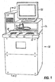
- the blocking apparatus 30 includes a cabinet having a top 32 and a hood structure 34 for partially enclosing the top 32.
- a lens transporter 36 is moveably mounted on a first linear actuator 38 affixed to the top 32.
- the first linear actuator 38 has a first servo motor or stepper motor unit for moving the lens transporter 36 therealong and for monitoring its position.
- the blocking apparatus 30 has, aligned with the first linear actuator 38 and incorporated into the top 32 of the cabinet, an imaging station 40, a probing station 42 and a lens blocking station 44.
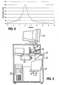
- the blocking apparatus 30 encloses (cf. FIG. 2 ) a camera 46 focused on the imaging station 40, an adhesive composition reservoir 48 and a pumping unit 50 for pumping the adhesive composition to the lens blocking station 44.
- the blocking apparatus 30 further includes a controller in the form of a central processing unit 52 for controlling its operation.
- the imaging station 40 is utilized for lens orientation to ensure that a lens blank 54 is property aligned and oriented at the outset of the lens blocking process, with the aid of a screen 56 for displaying lens orientation information generated by the central processing unit 52 on the basis of image information received from the camera 46.
- a screen 56 for displaying lens orientation information generated by the central processing unit 52 on the basis of image information received from the camera 46.
- the lens blank 54 is transported by the lens transporter 36 from the imaging station 40 to the probing station 42 for probing the blocking face 58 of the lens blank 54.
- the lens transporter 36 and the probing station 42 can be taken from document US 2005/0139309 A .
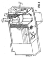
- the lens blocking station 44 includes a UV and visible light transmissive lens block support 60 for receiving and supporting a lens block 62 with a lens mounting face 64 of the lens block 62 facing upwardly.
- the lens block 62 should be of a transparent material capable of transmitting at least light in the UV spectrum and preferably also in the visible spectrum.
- lens block 62 As to further structural and functional features of the lens block 62, in particular the clamping portion of the lens block 62 via which the lens block 62 can be held in the lens blocking station 44 and later fixed on a spindle of a surfacing machine (not shown), reference is made to document US 2005/0250430 A .
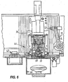
- a UV light source 66 (see FIG. 6 ) is associated with the lens block support 60 in that it, is mounted so as to direct light through an aperture 68 in the lens block support 60 which in turn directs the UV light through the UV transmissive lens block 62.
- a light source actuator which may form part of the central processing unit 52 is connected to the UV light source 66 to control activation and de-activation of the UV light source 66.
- the UV light source 66 could incorporate a flash lamp which emits a pulse of high intensity short duration light within the UV spectrum and in the visible spectrum.
- a dispenser for dispensing an adhesive composition curable by UV/visible light is generally indicated by reference 70.
- the dispenser 70 has a dispenser nozzle 72 at one end of a dispenser arm 74.
- An arm actuator - which may be a motor such as illustrated by reference 76 or a linear or other actuator - may be provided to move the dispenser arm 74 from a deployed position adjacent the lens mounting face 64 ( FIG. 5 ) to a retracted position clear of the lens mounting face 64 ( FIG. 4 ) and the lens transporter 36 (and vice versa) so as not to interfere with the placement of the lens blank 54 over the lens mounting face 64 of the lens block 62.
- the dispenser arm 74 merely controls position of the dispenser nozzle 72. Accordingly the dispenser arm 74 can be telescopic rather than rotatable as illustrated and possibly controlled by a linear actuator such as a fluid pressure actuated piston within a cylinder.
- the dispenser nozzle 72 fluidly communicates with the adhesive composition reservoir 48 through the pumping unit 50 which supplies the adhesive composition to the dispenser nozzle 72.
- the adhesive composition reservoir 48 may be pressurized thereby obviating the need for a pump.
- the adhesive composition reservoir 48 as a - preferably replaceable - pre-filled unit already contains the ready-mixed adhesive composition comprised of an un-polymerized, i.e. liquid UV/VIS curable adhesive and a suitable filler as a non polymerizing solid.
- the blocking apparatus may be equipped with a mixing unit for preparing the adhesive composition from the above components that could be stored in appropriate containers replaceably mounted to the blocking apparatus 30.
- the dispenser nozzle 72 is equipped with a valve or other shutoff mechanism which communicates with the central processing unit 52 to control dispensing of the adhesive composition through the dispenser nozzle 72 when the dispenser nozzle 72 is in the deployed position.
- a valve or other shutoff mechanism which communicates with the central processing unit 52 to control dispensing of the adhesive composition through the dispenser nozzle 72 when the dispenser nozzle 72 is in the deployed position.
- Different control arrangements may be used. A simple form of control is to monitor the time that the dispenser nozzle 72 is held open. Other controls such as a metering pump may be utilized. Generally whatever control is selected should dispense a measured amount of adhesive composition which will substantially fill the gap between the blocking face 58 of the lens blank 54 and the lens mounting face 64 of the lens block 62.
- a measured amount of UV/VIS curable adhesive composition is dispensed via the dispenser nozzle 72 of the dispenser 70 on the lens mounting face 64 of the lens block 62.
- the lens blank 54 is moved by means of the lens transporter 36 over the lens block 62 with the blocking face 58 of the lens blank 54 facing the lens mounting face 64.
- the lens transporter 36 then moves the lens blank 54 toward to the lens mounting face 64 and into the liquid adhesive composition 78 (see FIG. 6 ) until the blocking face 58 of the lens blank 54 is a predetermined distance from the lens mounting face 64 of the lens block 62.
- the amount of adhesive composition 78 required can be calculated and dispensed automatically without operator intervention.
- UV light is generated by the UV light source 66 and transmitted through the lens block 62 at a wavelength, and intensity and for a duration sufficient to cause the adhesive composition 78 to cure thereby bonding the lens blank 54 to the lens block 62.
- the lens block 62 with the lens blank 54 attached thereto would be removed from the lens blocking station 44 and released from the lens transporter 36.
- FIG. 7 illustrates blocking results obtained by a blocking process that comprises the following steps:
- FIG. 7 shows the same lens blanks 54 as those of FIG. 11 in terms of blocking face curvature (a) 0.5 diopters, b) 2 diopters, c) 6 diopters, and d) 10 diopters), however now blocked on only one block curve of 5 diopters in this instance. This helps illustrate the issues associated with a reduced number of block curves, and why the proposed solution is felt to be advantageous.
- FIG. 7 it first appears as though the usage of blocking material will be considerably greater than that seen to be used in FIG. 11 .
- the amount of blocking material used is however not as great as one would initially think, given the reason that the single block curve can be chosen to best fit the majority of spectacle lenses in a statistical distribution of lens base curves.
- FIG. 9 illustrates a typical base (front) curve distribution for a given population. Because of this distribution, and also considering proper selection of an optimal block curve, the blocking material usage is only increased by 10 to 15% when using one block curve compared to 7 block curves. If two block curves are used, then the increase in blocking material usage is calculated at only 6% more than with 7 block curves. This marginal increase in blocking material consumption is easily compensated by the cost reduction associated with managing only one or two block curves versus the high number of curves typically encountered.
- FIG. 8 it illustrates blocking results obtained by a further blocking process that comprises the following steps:
- the adhesive composition 78 comprising the adhesive curable by UV or visible light that is liquid in the un-polymerized state, and the filler as a non polymerizing solid, the following is to be noted.
- blocking means to release the adhesive bond between lens and adhesive composition through chemical, thermal, mechanical or some other means or any practical combination thereof.
- Multifunctional fillers or special combinations of fillers can be used to either maintain or modify the material properties while simultaneously reducing shrinkage, exothermic heat of reaction, and cost.
- Another potential function of the filler is to modify the adhesive properties under certain controlled conditions to permit easier deblocking.
- the cured material typically needs to be sufficiently rigid to prevent flexing and movement of the lens or the area of the lens in the immediate vicinity of the cutting tool during the machining process. Having a flexible blocking material however makes it easier to "peel” this material off the lens during the deblocking process. A hard and brittle material is difficult to peel off, and tends to break into smaller pieces, whereas a soft pliable and cohesive material will more easily peel off in one piece.
- the preferred material will have either a rigidity level sufficiently high to allow surfacing while being sufficiently low for deblocking, or it could be subjected to a "softening" process prior to deblocking.
- This "softening" process could for example be heating of the blocking material by immersion in warm water, or exposure to other forms and/or wavelengths of radiation such as IR or microwaves.
- the adhesive composition should be designed to better support deblocking with certain modifiable properties such as reduction in hardness, possibly also combined with reduction in adhesiveness.
- a small amount of metal fibers, granules, or powder can be added to the filler to enhance heating of the cured blocking material in microwave energy.
- a small quantity (1 or 2% by weight of the composition in total) of fine aluminum fibers mixed with the liquid adhesive are not enough to prevent curing since the UV radiation can still easily penetrate the adhesive, but yet provides sufficient absorption of microwave energy to significantly accelerate heating of the material.
- a microwave exposure time of 15 seconds is all that is needed to raise the material temperature from 30°C by 25° as compared to 20 seconds without the aluminum fibers.
- E-Caprolactone also Polycaprolactone
- E-Caprolactone is a thermoplastic monomer, and is sufficiently translucent to allow UV and/or visible light transmission, and therefore allow curing of a matrix of liquid UV adhesive and e-Caprolactone particles as a non polymerizing solid filler. Fill ratios as high as 65% by weight of e-Caprolactone were successfully cured and tested for hardness and adhesion to the lens blank and lens block.
- this material can be selected to be quite hard (e.g., between 50 and 70 Shore D), then, after surfacing, the cured blocking material can be heated and allowed to reach a point where the e-Caprolactone particles are soft (e.g., between 10 and 40 shore D) however not liquid. These temperatures are sufficiently low (between 35° and 60°C for instance) so as to not damage the lens.
- the UV/VIS cured adhesive component in the matrix stays solid, but the e-Caprolactone particles, being significantly softer at these temperatures, cause the whole matrix to be softer, and thus considerably improve the ease of removal of the blocking material from the lens.
- E-Caprolactone has a relatively low Glass Transition Temperature (Tg) so all processing would be done at higher than Tg in this case. Other materials similar to e-Caprolactone can also be identified.
- Another variation is to use a filler material with a Tg above surfacing process temperatures (typically close to room temperature), yet lower than temperatures that could permanently damage a surfaced lens (80°C).
- the MatWeb database www.matweb.com
- the MatWeb database has listed 235 polymer materials with a Tg between 25° and 80°C. These can be used to achieve certain mechanical properties at process temperatures (e.g., high stiffness and hardness), then change these mechanical properties by raising the temperature above Tg.
- One such material of interest is ExxonMobil "Escor AT320 EMA-AA Terpolymer”. This is an Ethyl-Methyl-Acrylate-Acrylic Acid. It is solid at room temperature and can be mixed in solid particle form with the liquid UV/VIS curable adhesive material. It provides an excellent surface for bonding to acrylate based UV/VIS curable adhesive materials since it is itself acrylate based.
- Ethacrylate resins can for example be High Methacrylate Resins, Ethyl Methacrylate Resins, Methacrylate Copolymer Resins, or Butyl Methacrylate Resins. Their properties range from low to very high molecular weights, and Tukon hardness between 1 and 20 (Knoop No.), and Tg between 15°C and 110°C.
- EVACITE ® 2550 Metal/ n-Butyl methacrylate copolymer
- Tg 36°C. It is relatively soft with Knoop hardness number of 4 but capable, if used with rather high fill percentages (60% to 70%), to ensure sufficient stiffness for surfacing, while facilitating deblocking due to the relatively low hardness and particular thermal properties.
- An added benefit to these products is that they can be directly purchased in a small diameter spherical bead form. The typical bead diameters are between 10 to 200 microns, which makes them directly usable without preprocessing to grind larger pellets down to an acceptable size.
- Filler should also be non abrasive, and non destructive to cutter tools. If one cuts through the cured blocking material with a cutting or grinding tool it should not damage the tool. Some increased wear can be acceptable in certain circumstances however the amount of increased wear t'olerated by the customer is typically driven by total process economics.
- the preferred filler particle geometry (generally spherical) and size (smaller than 2 mm, more preferably equal to or less than 1 mm) have been discussed already.
- Another important property of the filler is that it must not prevent or unduly slow down the curing process by blocking or somehow inhibiting the UV and/or visible electromagnetic energy from reaching the photoinitiators imbedded in the UV/VIS curable adhesive material. Thus transparency and/or translucency to the photo active wavelengths is considered very important for the selection of a compatible filler.
- a still further desirable feature or function of the filler material is to reduce outgassing by incorporating a very low outgassing material(s), and thus significantly reduce the "vacuum pumping times" if and when a complete blocked lens is introduced into a vacuum chamber typically used in thin film coating processes.
- Three major sources of outgassing can be VOC emissions (Volatile Organic Compounds) from solvents, uncured remainders of liquid resin, and water moisture trapped within the blocking material. All three of these materials can vaporize in a vacuum and create a situation where it is difficult or slower than desired to reach the level of vacuum required for the coating process.
- the preferred approach is to avoid introducing any solvents in the liquid compound.
- This problem is generally addressed by again providing a UV/VIS transparent/translucent filler, and providing better curing technology, such as a better focussed high powered light source to scan the lens block, or ultra high energy XENON flash lamp technology.
- the third situation is that of moisture content. In this case it becomes important to choose low moisture absorption material(s) for the filler. Examples of such materials are polycarbonate and PET based materials just to name two.
- a strongly preferred approach is to directly re-use the UV/VIS cured adhesive material in a reground state as a filler.
- the operator can simply put it into a small grinder designed to regrind the material to the proper particle size.
- This reground material is then mixed with new uncured UV/VIS curable adhesive material in the proper mixing ratio using known measuring technology and apparatus and methods.
- Metering screws using a mixing nozzle is one approach.
- the preferred mixing ratios are between 40%/60% and 70%/30% filler granulate vs. liquid UV/VIS curable adhesive material.
- This concept allows continuous or on demand mixing of the two components in relatively accurate mixing ratios, and can also be used to deliver the correct amount of mixed adhesive composition to the lens block.
- Another simpler approach is to simply weigh the correct amount of components for a batch, and mix with a powered hand mixer such as a hand drill assisted paint mixer.
- One of the main advantages to using reground material is that all the shrinkage and exothermic heat reduction are obtained that would normally be expected with other fillers, while simultaneously reducing cost even more than if these other fillers were used.
- the cured blocking material would normally end up in disposal, so recycling 50% to 70% of it has both economic and environmental benefits. Cost benefits are realized since its cost is near zero. The only costs are those of handling, grinding, and mixing. Environmental benefits come from the fact that the disposal volumes are significantly reduced.
- Another advantage is that new uncured material bonds very well to the cured material due to chemical similarity between the two.
- Still another benefit is that any variation in mixing ratios will not affect the final mechanical and thermal properties such as temperature dependent hardness/flexibility, softening point, etc. This simplifies mixing and quality control of the mixed adhesive composition since tolerances to mixing errors are much greater.
- Other advantages are those of consistent and predictable UV transmissibility, "all in one" compound design not affected by foreign or not completely compatible fillers, no filler quality variation, etc.
- the General #3 blocking compound was formerly known as "ULTRAGRIP ® " sold by Micro Optics Design Corporation of Moncton, New Brunswick, Canada).
- the individual components of the adhesive composition i.e. the liquid UV curable adhesive and the solid filler particles were mixed thoroughly by hand.
- the mixed product cured successfully due to the fact that the "white” C6500 particles transmitted enough of the photo active wavelengths to obtain complete curing after 10 seconds of exposure time using a "Fusion” UV lamp (which can be obtained from Fusion UV Systems, Inc. 910 Clopper Road Gaithersburg, Maryland 20878-1357 USA) mounted with a "D" type bulb.
- a "Fusion” UV lamp which can be obtained from Fusion UV Systems, Inc. 910 Clopper Road Gaithersburg, Maryland 20878-1357 USA
- the main disadvantages to this material seemed to be the large particle size, and the relatively high cost of the C6500.
- the hardness at room temperature of the mixed and cured sample was measured to be in the range of 39 to 55 Shore D which very closely matches the hardness of cured General #3 (38 Shore D) and C6500 measured at 57 Shore D. A multiple reading average gave a value of 45.6 Shore D.
- the reason for the large variance and close correlation to the hardness's of each component has been attributed to the large particle size and the probability of measuring with the gage point directly over a C6500 particle, or in between particles.
- the C6500 particles were covered by a non uniform thickness of General #3, which further added to the unpredictability of the measurements.
- a softening of the cured adhesive composition measured as a reduction in average hardness to 35 shore D at a deblocking temperature of 50°C was however clearly seen, and facilitated deblocking.
- the large particle size of the C6500 was seen to be a problem for two major reasons; the first was that this increases the minimum gap achievable between the lens blank and the lens block, therefore increasing the quantity of material needed for blocking.
- the second problem was seen to be irregular shrinkage causing a small ripples or variation in optical power in very thin lenses. This is explained by shrinkage between granules being greater than the shrinkage directly over a granule, with another possible contributing factor being the variance in hardness causing a variation in support stiffness provided by the cured blocking material.
- Elvacite ® 2550 used had generally spherical or ellipsoidal particles of irregular diameters ranging from 15 to 460 microns, with an average particle size of 350 microns.
- the 350 micron particle size was also seen to be a benefit for providing uniform shrinkage and support in addition to minimum gaps of less than 0.5 mm being possible.
- the UV transparent/translucent properties of the Elvacite ® 2550 filler made it very easy to cure the adhesive composition with all the different light sources that were tested.
- a third compound was prepared using ExxonMobil "Escor AT320 EMA-AA Terpolymer” .
- the 60% by weight of Escor AT320 filler to 40% by weight of General #3 was again used.
- This filler was irregular, and the particle size was such that it passed through a 1.5 mm screen.
- This adhesive composition is seen to be an advantageous material from the thermal properties perspective, and was tested for support at a surface processing temperature of 23°C and deblocking temperature between 55°C and 60°C. Hardness reduced on a slope of 0.4 Shore D per °C, but started at a relatively low 25 Shore D hardness at 25°C. This hardness is lower than the General# 3 hardness of 38 Shore D so it is felt that other products from this filler material family may provide better stiffness at surface processing temperatures between 20 and 25°C.
- a fourth compound was prepared and tested using a filler made from cured, i.e. polymerized pure General #3 at 50% by weight and liquid (uncured) General #3 at 50% by weight.
- the final cured adhesive composition is always General #3 since the filler is also the same General #3.
- the cured material was ground to have particle sizes between 0.5 and 1.5 mm, and an average size of 1 mm. These particles were very irregular in shape due to the grinding process used. Higher fill ratios were difficult to obtain, possibly due to the irregular particle geometries.
- This material had all of the advantages of other filled materials tested; namely lower shrinkage, and lower exothermic heat of polymerization.
- the polymerized state i.e. as a non polymerizing solid filler it is UV transparent and forms a very coherent solid mass of material with identical mechanical and thermal properties to that of the unfilled material.
- Major advantages of this approach to recycling the blocking material itself are those of low cost and of reduced material wastage.
- a fifth blocking material was prepared from the uncured adhesive composition according to EXAMPLE 4 above by adding 2% by weight of the filler in total of small aluminum fibers ("Aluminiumfasern Al Mg S Kurzmaschine F35") purchased from Alroko GmbH & Co. KG, of Hamburg, Germany.
- the fibers were very irregular in size and shape. They ranged in length from 0.5 mm to 3 mm, and varied in diameter from 0.1 to 0.5 mm.
- the purpose of the added fibers was simply to shorten the heating time using microwave energy. This proved to be very effective for this purpose.
- a new lens blocking material (adhesive composition) is proposed that essentially overcomes the drawbacks of previous blocking materials.
- This new material combines traditional UV and/or visible light (VIS) curable polymer materials with specially selected filler(s) as a non polymerizing solid in order to achieve or improve certain desirable material properties, including those of low shrinkage, low exothermic heat of polymerization, and improving the ability to deblock, while simultaneously reducing the high cost associated with such UV/VIS radiation curable materials.
- the new material is being used in methods for blocking a lens blank onto a lens block with a lens mounting face that has a pre-determined block curve, in which the number of different block curves required to cover the full range of standard lenses is minimized.
Priority Applications (9)
| Application Number | Priority Date | Filing Date | Title |
|---|---|---|---|
| EP07013158.6A EP2011604B2 (de) | 2007-07-05 | 2007-07-05 | Verfahren zum Blocken eines Linsenrohlings, Haftmittelzusammensetzung und deren Verwendung beim Blocken von Linsen |
| ES07013158T ES2368349T5 (es) | 2007-07-05 | 2007-07-05 | Procedimiento de bloqueo de un primordio de lente, composición adhesiva y uso de este último para el bloqueo de las lentes |
| AT07013158T ATE515369T1 (de) | 2007-07-05 | 2007-07-05 | Verfahren zum blocken eines linsenrohlings, haftmittelzusammensetzung und deren verwendung beim blocken von linsen |
| US12/602,874 US8382932B2 (en) | 2007-07-05 | 2008-06-28 | Method for blocking a lens blank, adhesive composition and use of the latter in lens blocking |
| PCT/EP2008/005306 WO2009003660A1 (en) | 2007-07-05 | 2008-06-28 | Method for blocking a lens blank, adhesive composition and use of the latter in lens blocking |
| BRPI0813786-2A BRPI0813786B1 (pt) | 2007-07-05 | 2008-06-28 | Método para bloquear uma peça para lente, composição adesiva e uso da última no bloqueio de lente |
| CN2008800181601A CN101678526B (zh) | 2007-07-05 | 2008-06-28 | 粘合镜片毛坯的方法及粘结剂组合物 |
| JP2010513768A JP5129324B2 (ja) | 2007-07-05 | 2008-06-28 | レンズブランクをブロッキングするための方法、接着剤配合物及びレンズブロッキングにおける接着剤配合物の使用 |
| HK10104497.8A HK1136801A1 (en) | 2007-07-05 | 2010-05-10 | Method for blocking a lens blank and adhesive composition |
Applications Claiming Priority (1)
| Application Number | Priority Date | Filing Date | Title |
|---|---|---|---|
| EP07013158.6A EP2011604B2 (de) | 2007-07-05 | 2007-07-05 | Verfahren zum Blocken eines Linsenrohlings, Haftmittelzusammensetzung und deren Verwendung beim Blocken von Linsen |
Publications (3)
| Publication Number | Publication Date |
|---|---|
| EP2011604A1 true EP2011604A1 (de) | 2009-01-07 |
| EP2011604B1 EP2011604B1 (de) | 2011-07-06 |
| EP2011604B2 EP2011604B2 (de) | 2020-12-09 |
Family
ID=39811487
Family Applications (1)
| Application Number | Title | Priority Date | Filing Date |
|---|---|---|---|
| EP07013158.6A Active EP2011604B2 (de) | 2007-07-05 | 2007-07-05 | Verfahren zum Blocken eines Linsenrohlings, Haftmittelzusammensetzung und deren Verwendung beim Blocken von Linsen |
Country Status (9)
| Country | Link |
|---|---|
| US (1) | US8382932B2 (de) |
| EP (1) | EP2011604B2 (de) |
| JP (1) | JP5129324B2 (de) |
| CN (1) | CN101678526B (de) |
| AT (1) | ATE515369T1 (de) |
| BR (1) | BRPI0813786B1 (de) |
| ES (1) | ES2368349T5 (de) |
| HK (1) | HK1136801A1 (de) |
| WO (1) | WO2009003660A1 (de) |
Cited By (26)
| Publication number | Priority date | Publication date | Assignee | Title |
|---|---|---|---|---|
| DE102008023093A1 (de) | 2008-05-09 | 2009-11-12 | Satisloh Ag | Vorrichtung zum Blocken von Werkstücken, insbesondere Brillengläsern, für deren Bearbeitung und/oder Beschichtung |
| EP2266753A1 (de) | 2008-02-25 | 2010-12-29 | Satisloh AG | Sperrstück zum Halten eines optischen Werkstücks, insbesondere eines Brillenglases, zu dessen Bearbeitung und Verfahren zur Herstellung von Brillengläsern entsprechend einer Vorgabe |
| DE102010010334A1 (de) | 2010-03-04 | 2011-09-08 | Satisloh Ag | Vorrichtung zum Abblocken von optischen Werkstücken, insbesondere Brillengläsern |
| WO2013075834A3 (de) * | 2011-11-23 | 2013-09-12 | Schneider Gmbh & Co. Kg | Verfahren und vorrichtung zum aufblocken von brillengläsern |
| US8684525B2 (en) | 2008-05-07 | 2014-04-01 | Schneider Gmbh & Co. Kg | Method for machining an eyeglass lens blank and eyeglass lens blank comprising a connecting material and block piece |
| DE102008022360C5 (de) * | 2008-05-06 | 2014-04-10 | Schneider Gmbh & Co. Kg | Blockstation zum Aufblocken von Brillenglasrohlingen auf ein Blockstück |
| DE202014009911U1 (de) | 2013-05-06 | 2015-01-16 | Satisloh Ag | Multimaterial Blockstück |
| EP2963458A1 (de) | 2014-07-05 | 2016-01-06 | Satisloh AG | Linsenrohling mit einer temporären Anti-Rutsch-Beschichtung für ein Verfahren zur Herstellung von Brillengläsern nach Rezept |
| EP3009230A1 (de) | 2014-10-15 | 2016-04-20 | Satisloh AG | Aufblockeinrichtung für ein Blockstück für ein Brillenglas und Verfahren zur Aushärtung |
| EP3124175A2 (de) | 2015-07-31 | 2017-02-01 | Satisloh AG | Verfahren zur bearbeitung von optischen werkstücken, insbesondere brillenlinsen aus kunststoff |
| EP3415273A1 (de) * | 2017-06-12 | 2018-12-19 | Essilor International | Vorrichtung zur adhäsiven blockierung eines halbfertigen optischen elements |
| EP3415274A1 (de) * | 2017-06-12 | 2018-12-19 | Essilor International | Blockierungsvorrichtung für ein halbfertiges optisches element |
| EP3415272A1 (de) * | 2017-06-12 | 2018-12-19 | Essilor International | Vorrichtung zum pneumatischen blockierung eines halbfertigen optischen elements |
| EP3479912A1 (de) | 2017-11-07 | 2019-05-08 | Satisloh AG | Reinigungsstation für optische elemente |
| DE102017010321A1 (de) | 2017-11-08 | 2019-05-09 | Satisloh Ag | Verfahren zur Fertigung von individuellen Brillenlinsen nach einem Rezeptauftrag |
| WO2019091928A1 (en) | 2017-11-07 | 2019-05-16 | Satisloh Ag | Optical elements holder device for a coating station |
| WO2019091929A1 (en) | 2017-11-07 | 2019-05-16 | Satisloh Ag | Method for manufacturing optical elements according to a prescription |
| EP3542956A1 (de) | 2018-03-23 | 2019-09-25 | Carl Zeiss Vision International GmbH | Verfahren zur herstellung von brillengläsern nach rezept |
| EP2011604B2 (de) † | 2007-07-05 | 2020-12-09 | Satisloh AG | Verfahren zum Blocken eines Linsenrohlings, Haftmittelzusammensetzung und deren Verwendung beim Blocken von Linsen |
| EP3747641A2 (de) | 2019-06-07 | 2020-12-09 | Schneider GmbH & Co. KG | Verfahren und vorrichtung zur herstellung von optischen linsen |
| DE102019004489A1 (de) * | 2019-06-07 | 2020-12-10 | Schneider Gmbh & Co. Kg | Verfahren und Vorrichtung zum Herstellen von optischen Linsen |
| EP3871882A1 (de) | 2020-02-27 | 2021-09-01 | Essilor International | Verfahren zum laminieren eines funktionellen films auf einen optischen gegenstand |
| CN113497872A (zh) * | 2020-04-08 | 2021-10-12 | Oppo(重庆)智能科技有限公司 | 贴片装置及贴片控制方法 |
| DE102021004831A1 (de) | 2021-09-24 | 2023-03-30 | Satisloh Ag | Verfahren zur spanenden bearbeitung von optischen werkstücken, insbesondere brillenlinsen aus kunststoff |
| DE102021005202A1 (de) | 2021-10-19 | 2023-04-20 | Satisloh Ag | Aufnahme für die Bearbeitung von optischen Werkstücken, insbesondere Brillenlinsen |
| EP4190489A1 (de) * | 2021-12-01 | 2023-06-07 | Essilor International | System und verfahren zum blockieren einer ophthalmischen linse mit einem einsatz |
Families Citing this family (13)
| Publication number | Priority date | Publication date | Assignee | Title |
|---|---|---|---|---|
| EP2138271B1 (de) * | 2008-06-26 | 2011-08-03 | Satisloh AG | Verfahren zur Herstellung von Brillenlinsen nach Rezept |
| DE102009061843B3 (de) | 2009-10-07 | 2021-10-28 | Satisloh Ag | Vorrichtung zum Abblocken von optischen Werkstücken, insbesondere Brillengläsern |
| DE102009048590B4 (de) | 2009-10-07 | 2020-06-18 | Satisloh Ag | Vorrichtung zum Abblocken von optischen Werkstücken, insbesondere Brillengläsern |
| US20130303060A1 (en) * | 2010-11-26 | 2013-11-14 | Schneider Gmbh & Co. Kg | Block piece |
| TW201243009A (en) * | 2011-11-15 | 2012-11-01 | feng-sheng Huang | Optical glue mixture used in bubble removing process |
| LU92190B1 (en) * | 2013-05-06 | 2014-11-07 | Satisloh Gmbh | Multi part blocking piece |
| US10336003B2 (en) | 2014-07-22 | 2019-07-02 | Blue Photon Technology & Workholding Systems LLC | Method and devices to minimize work-piece distortion due to adhering stresses and changes in internal stresses |
| EP3204188B1 (de) | 2014-10-07 | 2021-09-01 | Shamir Optical Industry Ltd. | Verfahren und vorrichtung zur inspektion und optionalen überarbeitung von blockierten ophthalmischen linsen |
| EP3138886A1 (de) * | 2015-09-02 | 2017-03-08 | Allnex Belgium S.A. | Verfahren zum verkleben unter verwendung einer strahlungshärtbaren klebezusammensetzung mit kurzen fasern |
| DE102017001679B4 (de) * | 2017-02-22 | 2019-05-09 | Schneider Gmbh & Co. Kg | Vorrichtung und Verfahren zum Abblocken einer Linse |
| EP3797928B1 (de) * | 2019-09-27 | 2022-11-09 | Essilor International | Verfahren zur blockierung eines optischen elements und zugehörige vorrichtung |
| EP3936280A1 (de) | 2020-07-07 | 2022-01-12 | Satisloh AG | Transportträger für ein automatisiertes linsenherstellungsverfahren und zugehörige herstellungsanlage |
| CN114763215A (zh) * | 2021-01-12 | 2022-07-19 | 泰科电子(上海)有限公司 | 用于工件加工的通用平台 |
Citations (2)
| Publication number | Priority date | Publication date | Assignee | Title |
|---|---|---|---|---|
| WO1994008788A1 (en) * | 1992-10-13 | 1994-04-28 | Loctite Corporation | Lens blocking/deblocking method |
| US20050139309A1 (en) * | 2001-08-31 | 2005-06-30 | Marc Savoie | Method, apparatus and adhesive composition for ophthalmic lens blocking |
Family Cites Families (10)
| Publication number | Priority date | Publication date | Assignee | Title |
|---|---|---|---|---|
| US5763075A (en) * | 1996-09-13 | 1998-06-09 | Minnesota Mining And Manufacturing Company | Polycaprolactone lens blocking material |
| US5885700A (en) † | 1995-09-18 | 1999-03-23 | Minnesota Mining And Manufacturing Company | Thermoplastic lens blocking material |
| AU7360696A (en) * | 1995-09-18 | 1997-04-09 | Minnesota Mining And Manufacturing Company | Thermoplastic lens blocking material |
| WO1997033742A1 (en) * | 1996-03-11 | 1997-09-18 | Innotech, Inc. | Optical lens preforms |
| JP2004186254A (ja) * | 2002-11-29 | 2004-07-02 | Furukawa Electric Co Ltd:The | 加工体製造方法 |
| JP2004330327A (ja) * | 2003-05-02 | 2004-11-25 | Soken Chem & Eng Co Ltd | レンズの切削・研磨加工に用いるレンズ固定用部材及びそれを用いるレンズの切削・研磨加工方法 |
| US7439278B2 (en) * | 2004-05-04 | 2008-10-21 | Essilor International Compagnie Generale D'optique | Curable adhesive composition and its use in the optical field |
| DE102004023036A1 (de) * | 2004-05-06 | 2005-12-29 | Loh Engineering Ag, Oensingen | Blockstück zum Haltern eines optischen Werkstücks, insbesondere einer Brillenlinse, für dessen Bearbeitung |
| CN100395614C (zh) * | 2004-08-16 | 2008-06-18 | 鸿富锦精密工业(深圳)有限公司 | 导光板制造方法 |
| ATE515369T1 (de) † | 2007-07-05 | 2011-07-15 | Satisloh Ag | Verfahren zum blocken eines linsenrohlings, haftmittelzusammensetzung und deren verwendung beim blocken von linsen |
-
2007
- 2007-07-05 AT AT07013158T patent/ATE515369T1/de not_active IP Right Cessation
- 2007-07-05 ES ES07013158T patent/ES2368349T5/es active Active
- 2007-07-05 EP EP07013158.6A patent/EP2011604B2/de active Active
-
2008
- 2008-06-28 JP JP2010513768A patent/JP5129324B2/ja active Active
- 2008-06-28 CN CN2008800181601A patent/CN101678526B/zh active Active
- 2008-06-28 WO PCT/EP2008/005306 patent/WO2009003660A1/en active Application Filing
- 2008-06-28 US US12/602,874 patent/US8382932B2/en active Active
- 2008-06-28 BR BRPI0813786-2A patent/BRPI0813786B1/pt active IP Right Grant
-
2010
- 2010-05-10 HK HK10104497.8A patent/HK1136801A1/xx unknown
Patent Citations (2)
| Publication number | Priority date | Publication date | Assignee | Title |
|---|---|---|---|---|
| WO1994008788A1 (en) * | 1992-10-13 | 1994-04-28 | Loctite Corporation | Lens blocking/deblocking method |
| US20050139309A1 (en) * | 2001-08-31 | 2005-06-30 | Marc Savoie | Method, apparatus and adhesive composition for ophthalmic lens blocking |
Cited By (41)
| Publication number | Priority date | Publication date | Assignee | Title |
|---|---|---|---|---|
| EP2011604B2 (de) † | 2007-07-05 | 2020-12-09 | Satisloh AG | Verfahren zum Blocken eines Linsenrohlings, Haftmittelzusammensetzung und deren Verwendung beim Blocken von Linsen |
| EP2266753A1 (de) | 2008-02-25 | 2010-12-29 | Satisloh AG | Sperrstück zum Halten eines optischen Werkstücks, insbesondere eines Brillenglases, zu dessen Bearbeitung und Verfahren zur Herstellung von Brillengläsern entsprechend einer Vorgabe |
| DE102008022360C5 (de) * | 2008-05-06 | 2014-04-10 | Schneider Gmbh & Co. Kg | Blockstation zum Aufblocken von Brillenglasrohlingen auf ein Blockstück |
| US8684525B2 (en) | 2008-05-07 | 2014-04-01 | Schneider Gmbh & Co. Kg | Method for machining an eyeglass lens blank and eyeglass lens blank comprising a connecting material and block piece |
| DE102008023093A1 (de) | 2008-05-09 | 2009-11-12 | Satisloh Ag | Vorrichtung zum Blocken von Werkstücken, insbesondere Brillengläsern, für deren Bearbeitung und/oder Beschichtung |
| DE102010010334A1 (de) | 2010-03-04 | 2011-09-08 | Satisloh Ag | Vorrichtung zum Abblocken von optischen Werkstücken, insbesondere Brillengläsern |
| WO2011107227A1 (de) | 2010-03-04 | 2011-09-09 | Satisloh Ag | Vorrichtung zum abblocken von optischen werkstücken, insbesondere brillengläsern |
| US9694465B2 (en) | 2011-11-23 | 2017-07-04 | Schneider Gmbh & Co. Kg | Method and device for blocking eyeglass lenses |
| WO2013075834A3 (de) * | 2011-11-23 | 2013-09-12 | Schneider Gmbh & Co. Kg | Verfahren und vorrichtung zum aufblocken von brillengläsern |
| DE202014009911U1 (de) | 2013-05-06 | 2015-01-16 | Satisloh Ag | Multimaterial Blockstück |
| EP2963458A1 (de) | 2014-07-05 | 2016-01-06 | Satisloh AG | Linsenrohling mit einer temporären Anti-Rutsch-Beschichtung für ein Verfahren zur Herstellung von Brillengläsern nach Rezept |
| US10259096B2 (en) | 2014-10-15 | 2019-04-16 | Satisloh Ag | Blocking unit for a block piece for a spectacle lens and process of curing |
| EP3009230A1 (de) | 2014-10-15 | 2016-04-20 | Satisloh AG | Aufblockeinrichtung für ein Blockstück für ein Brillenglas und Verfahren zur Aushärtung |
| WO2016058785A1 (en) * | 2014-10-15 | 2016-04-21 | Satisloh Ag | Blocking unit for a block piece for a spectacle lens and process of curing |
| EP3124175A2 (de) | 2015-07-31 | 2017-02-01 | Satisloh AG | Verfahren zur bearbeitung von optischen werkstücken, insbesondere brillenlinsen aus kunststoff |
| DE102015009973A1 (de) | 2015-07-31 | 2017-02-02 | Satisloh Ag | Verfahren zur Bearbeitung von optischen Werkstücken, insbesondere Brillenlinsen aus Kunststoff |
| WO2018229025A1 (en) * | 2017-06-12 | 2018-12-20 | Essilor International | Device for adhesively blocking a semi-finished optical element |
| WO2018229024A1 (en) * | 2017-06-12 | 2018-12-20 | Essilor International | Device for pneumatically blocking a semi-finished optical element |
| EP3415272A1 (de) * | 2017-06-12 | 2018-12-19 | Essilor International | Vorrichtung zum pneumatischen blockierung eines halbfertigen optischen elements |
| WO2018229026A1 (en) * | 2017-06-12 | 2018-12-20 | Essilor International | Blocking device for a semi-finished optical element |
| EP3415274A1 (de) * | 2017-06-12 | 2018-12-19 | Essilor International | Blockierungsvorrichtung für ein halbfertiges optisches element |
| EP3415273A1 (de) * | 2017-06-12 | 2018-12-19 | Essilor International | Vorrichtung zur adhäsiven blockierung eines halbfertigen optischen elements |
| EP3479912A1 (de) | 2017-11-07 | 2019-05-08 | Satisloh AG | Reinigungsstation für optische elemente |
| WO2019091925A1 (en) | 2017-11-07 | 2019-05-16 | Satisloh Ag | Cleaning station for optical elements |
| WO2019091928A1 (en) | 2017-11-07 | 2019-05-16 | Satisloh Ag | Optical elements holder device for a coating station |
| WO2019091929A1 (en) | 2017-11-07 | 2019-05-16 | Satisloh Ag | Method for manufacturing optical elements according to a prescription |
| DE102017010321A1 (de) | 2017-11-08 | 2019-05-09 | Satisloh Ag | Verfahren zur Fertigung von individuellen Brillenlinsen nach einem Rezeptauftrag |
| EP3542956A1 (de) | 2018-03-23 | 2019-09-25 | Carl Zeiss Vision International GmbH | Verfahren zur herstellung von brillengläsern nach rezept |
| WO2019179660A1 (en) | 2018-03-23 | 2019-09-26 | Carl Zeiss Vision International Gmbh | Method for manufacturing spectacle lenses according to a prescription |
| EP3747641A2 (de) | 2019-06-07 | 2020-12-09 | Schneider GmbH & Co. KG | Verfahren und vorrichtung zur herstellung von optischen linsen |
| DE102019004489A1 (de) * | 2019-06-07 | 2020-12-10 | Schneider Gmbh & Co. Kg | Verfahren und Vorrichtung zum Herstellen von optischen Linsen |
| EP3871882A1 (de) | 2020-02-27 | 2021-09-01 | Essilor International | Verfahren zum laminieren eines funktionellen films auf einen optischen gegenstand |
| WO2021170705A1 (en) | 2020-02-27 | 2021-09-02 | Essilor International | Method of laminating a functional film onto an optical article and optical article |
| CN113497872B (zh) * | 2020-04-08 | 2023-04-18 | Oppo(重庆)智能科技有限公司 | 贴片装置及贴片控制方法 |
| CN113497872A (zh) * | 2020-04-08 | 2021-10-12 | Oppo(重庆)智能科技有限公司 | 贴片装置及贴片控制方法 |
| DE102021004831A1 (de) | 2021-09-24 | 2023-03-30 | Satisloh Ag | Verfahren zur spanenden bearbeitung von optischen werkstücken, insbesondere brillenlinsen aus kunststoff |
| WO2023046937A1 (de) | 2021-09-24 | 2023-03-30 | Satisloh Ag | Verfahren zur spanenden bearbeitung von optischen werkstücken, insbesondere brillenlinsen aus kunststoff |
| DE102021005202A1 (de) | 2021-10-19 | 2023-04-20 | Satisloh Ag | Aufnahme für die Bearbeitung von optischen Werkstücken, insbesondere Brillenlinsen |
| WO2023066824A1 (de) | 2021-10-19 | 2023-04-27 | Satisloh Ag | Aufnahme für die bearbeitung von optischen werkstücken, insbesondere brillenlinsen |
| EP4190489A1 (de) * | 2021-12-01 | 2023-06-07 | Essilor International | System und verfahren zum blockieren einer ophthalmischen linse mit einem einsatz |
| WO2023099577A1 (en) * | 2021-12-01 | 2023-06-08 | Essilor International | System for blocking an ophthalmic lens with an insert |
Also Published As
| Publication number | Publication date |
|---|---|
| US20100170635A1 (en) | 2010-07-08 |
| US8382932B2 (en) | 2013-02-26 |
| HK1136801A1 (en) | 2010-07-09 |
| EP2011604B2 (de) | 2020-12-09 |
| CN101678526B (zh) | 2012-05-02 |
| BRPI0813786B1 (pt) | 2019-06-25 |
| ATE515369T1 (de) | 2011-07-15 |
| WO2009003660A1 (en) | 2009-01-08 |
| CN101678526A (zh) | 2010-03-24 |
| ES2368349T5 (es) | 2021-09-17 |
| ES2368349T3 (es) | 2011-11-16 |
| BRPI0813786A2 (pt) | 2014-12-30 |
| EP2011604B1 (de) | 2011-07-06 |
| JP5129324B2 (ja) | 2013-01-30 |
| JP2010532268A (ja) | 2010-10-07 |
Similar Documents
| Publication | Publication Date | Title |
|---|---|---|
| EP2011604B1 (de) | Verfahren zum Blocken eines Linsenrohlings, Haftmittelzusammensetzung und deren Verwendung beim Blocken von Linsen | |
| EP2963458B1 (de) | Linsenrohling mit einer temporären Anti-Rutsch-Beschichtung für ein Verfahren zur Herstellung von Brillengläsern nach Rezept | |
| KR101546813B1 (ko) | 렌즈 기재에 코팅되거나 코팅되지 않은 필름을 적용하는 방법 | |
| CN100453301C (zh) | 一种用于制造细磨线不可见的涂敷光学件的方法 | |
| EP2266753B1 (de) | Sperrstück zum Halten eines optischen Werkstücks, insbesondere eines Brillenglases, zu dessen Bearbeitung und Verfahren zur Herstellung von Brillengläsern entsprechend einer Vorgabe | |
| AU2006254990B2 (en) | Method of injection molding thin lenses and producing laminated photochromic lenses | |
| CN106794567B (zh) | 用于眼镜片的封阻件的封阻单元以及固化工艺 | |
| CN101243335B (zh) | 制造由透明材料制成的无可见表面处理线条的制品的方法和由此得到的制品 | |
| JP2018532150A (ja) | 3d印刷レンズの平滑化 | |
| TW201140127A (en) | Anti-dizzy polarized board and image display device using the polarized board | |
| EP2826592A1 (de) | Mehrteiliges Blockierstück | |
| JP2021502230A (ja) | 光学基板をコーティングするためのコーティングシステム、その方法、およびコーティングされた光学基板 | |
| EP3542956A1 (de) | Verfahren zur herstellung von brillengläsern nach rezept | |
| CN110383111A (zh) | 透镜的制造方法 | |
| CN107632364A (zh) | 一种镜片粘合工艺 | |
| SG172492A1 (en) | Method and apparatus for making polymeric resin-based optical components via ultra-violet radiation |
Legal Events
| Date | Code | Title | Description |
|---|---|---|---|
| PUAI | Public reference made under article 153(3) epc to a published international application that has entered the european phase |
Free format text: ORIGINAL CODE: 0009012 |
|
| AK | Designated contracting states |
Kind code of ref document: A1 Designated state(s): AT BE BG CH CY CZ DE DK EE ES FI FR GB GR HU IE IS IT LI LT LU LV MC MT NL PL PT RO SE SI SK TR |
|
| AX | Request for extension of the european patent |
Extension state: AL BA HR MK RS |
|
| 17P | Request for examination filed |
Effective date: 20090127 |
|
| AKX | Designation fees paid |
Designated state(s): AT BE BG CH CY CZ DE DK EE ES FI FR GB GR HU IE IS IT LI LT LU LV MC MT NL PL PT RO SE SI SK TR |
|
| 17Q | First examination report despatched |
Effective date: 20100428 |
|
| GRAP | Despatch of communication of intention to grant a patent |
Free format text: ORIGINAL CODE: EPIDOSNIGR1 |
|
| GRAS | Grant fee paid |
Free format text: ORIGINAL CODE: EPIDOSNIGR3 |
|
| GRAA | (expected) grant |
Free format text: ORIGINAL CODE: 0009210 |
|
| AK | Designated contracting states |
Kind code of ref document: B1 Designated state(s): AT BE BG CH CY CZ DE DK EE ES FI FR GB GR HU IE IS IT LI LT LU LV MC MT NL PL PT RO SE SI SK TR |
|
| REG | Reference to a national code |
Ref country code: GB Ref legal event code: FG4D |
|
| REG | Reference to a national code |
Ref country code: CH Ref legal event code: NV Representative=s name: KEMENY AG PATENTANWALTBUERO Ref country code: CH Ref legal event code: EP |
|
| REG | Reference to a national code |
Ref country code: IE Ref legal event code: FG4D |
|
| REG | Reference to a national code |
Ref country code: DE Ref legal event code: R096 Ref document number: 602007015591 Country of ref document: DE Effective date: 20110908 |
|
| REG | Reference to a national code |
Ref country code: NL Ref legal event code: VDEP Effective date: 20110706 |
|
| REG | Reference to a national code |
Ref country code: ES Ref legal event code: FG2A Ref document number: 2368349 Country of ref document: ES Kind code of ref document: T3 Effective date: 20111116 |
|
| PG25 | Lapsed in a contracting state [announced via postgrant information from national office to epo] |
Ref country code: SI Free format text: LAPSE BECAUSE OF FAILURE TO SUBMIT A TRANSLATION OF THE DESCRIPTION OR TO PAY THE FEE WITHIN THE PRESCRIBED TIME-LIMIT Effective date: 20110706 |
|
| REG | Reference to a national code |
Ref country code: AT Ref legal event code: MK05 Ref document number: 515369 Country of ref document: AT Kind code of ref document: T Effective date: 20110706 |
|
| PG25 | Lapsed in a contracting state [announced via postgrant information from national office to epo] |
Ref country code: BE Free format text: LAPSE BECAUSE OF FAILURE TO SUBMIT A TRANSLATION OF THE DESCRIPTION OR TO PAY THE FEE WITHIN THE PRESCRIBED TIME-LIMIT Effective date: 20110706 Ref country code: NL Free format text: LAPSE BECAUSE OF FAILURE TO SUBMIT A TRANSLATION OF THE DESCRIPTION OR TO PAY THE FEE WITHIN THE PRESCRIBED TIME-LIMIT Effective date: 20110706 Ref country code: SE Free format text: LAPSE BECAUSE OF FAILURE TO SUBMIT A TRANSLATION OF THE DESCRIPTION OR TO PAY THE FEE WITHIN THE PRESCRIBED TIME-LIMIT Effective date: 20110706 Ref country code: FI Free format text: LAPSE BECAUSE OF FAILURE TO SUBMIT A TRANSLATION OF THE DESCRIPTION OR TO PAY THE FEE WITHIN THE PRESCRIBED TIME-LIMIT Effective date: 20110706 Ref country code: IS Free format text: LAPSE BECAUSE OF FAILURE TO SUBMIT A TRANSLATION OF THE DESCRIPTION OR TO PAY THE FEE WITHIN THE PRESCRIBED TIME-LIMIT Effective date: 20111106 Ref country code: PT Free format text: LAPSE BECAUSE OF FAILURE TO SUBMIT A TRANSLATION OF THE DESCRIPTION OR TO PAY THE FEE WITHIN THE PRESCRIBED TIME-LIMIT Effective date: 20111107 Ref country code: LT Free format text: LAPSE BECAUSE OF FAILURE TO SUBMIT A TRANSLATION OF THE DESCRIPTION OR TO PAY THE FEE WITHIN THE PRESCRIBED TIME-LIMIT Effective date: 20110706 |
|
| PG25 | Lapsed in a contracting state [announced via postgrant information from national office to epo] |
Ref country code: GR Free format text: LAPSE BECAUSE OF FAILURE TO SUBMIT A TRANSLATION OF THE DESCRIPTION OR TO PAY THE FEE WITHIN THE PRESCRIBED TIME-LIMIT Effective date: 20111007 Ref country code: PL Free format text: LAPSE BECAUSE OF FAILURE TO SUBMIT A TRANSLATION OF THE DESCRIPTION OR TO PAY THE FEE WITHIN THE PRESCRIBED TIME-LIMIT Effective date: 20110706 Ref country code: LV Free format text: LAPSE BECAUSE OF FAILURE TO SUBMIT A TRANSLATION OF THE DESCRIPTION OR TO PAY THE FEE WITHIN THE PRESCRIBED TIME-LIMIT Effective date: 20110706 Ref country code: AT Free format text: LAPSE BECAUSE OF FAILURE TO SUBMIT A TRANSLATION OF THE DESCRIPTION OR TO PAY THE FEE WITHIN THE PRESCRIBED TIME-LIMIT Effective date: 20110706 Ref country code: CY Free format text: LAPSE BECAUSE OF FAILURE TO SUBMIT A TRANSLATION OF THE DESCRIPTION OR TO PAY THE FEE WITHIN THE PRESCRIBED TIME-LIMIT Effective date: 20110706 |
|
| REG | Reference to a national code |
Ref country code: CH Ref legal event code: PFA Owner name: SATISLOH AG Free format text: SATISLOH AG#NEUHOFSTRASSE 12#6340 BAAR (CH) -TRANSFER TO- SATISLOH AG#NEUHOFSTRASSE 12#6340 BAAR (CH) |
|
| REG | Reference to a national code |
Ref country code: HU Ref legal event code: AG4A Ref document number: E012326 Country of ref document: HU |
|
| PLBI | Opposition filed |
Free format text: ORIGINAL CODE: 0009260 |
|
| PG25 | Lapsed in a contracting state [announced via postgrant information from national office to epo] |
Ref country code: SK Free format text: LAPSE BECAUSE OF FAILURE TO SUBMIT A TRANSLATION OF THE DESCRIPTION OR TO PAY THE FEE WITHIN THE PRESCRIBED TIME-LIMIT Effective date: 20110706 Ref country code: CZ Free format text: LAPSE BECAUSE OF FAILURE TO SUBMIT A TRANSLATION OF THE DESCRIPTION OR TO PAY THE FEE WITHIN THE PRESCRIBED TIME-LIMIT Effective date: 20110706 |
|
| PLAX | Notice of opposition and request to file observation + time limit sent |
Free format text: ORIGINAL CODE: EPIDOSNOBS2 |
|
| 26 | Opposition filed |
Opponent name: SCHNEIDER GMBH & CO. KG Effective date: 20120330 |
|
| PG25 | Lapsed in a contracting state [announced via postgrant information from national office to epo] |
Ref country code: EE Free format text: LAPSE BECAUSE OF FAILURE TO SUBMIT A TRANSLATION OF THE DESCRIPTION OR TO PAY THE FEE WITHIN THE PRESCRIBED TIME-LIMIT Effective date: 20110706 Ref country code: RO Free format text: LAPSE BECAUSE OF FAILURE TO SUBMIT A TRANSLATION OF THE DESCRIPTION OR TO PAY THE FEE WITHIN THE PRESCRIBED TIME-LIMIT Effective date: 20110706 |
|
| PG25 | Lapsed in a contracting state [announced via postgrant information from national office to epo] |
Ref country code: DK Free format text: LAPSE BECAUSE OF FAILURE TO SUBMIT A TRANSLATION OF THE DESCRIPTION OR TO PAY THE FEE WITHIN THE PRESCRIBED TIME-LIMIT Effective date: 20110706 |
|
| REG | Reference to a national code |
Ref country code: DE Ref legal event code: R026 Ref document number: 602007015591 Country of ref document: DE Effective date: 20120330 |
|
| PLAF | Information modified related to communication of a notice of opposition and request to file observations + time limit |
Free format text: ORIGINAL CODE: EPIDOSCOBS2 |
|
| PLBB | Reply of patent proprietor to notice(s) of opposition received |
Free format text: ORIGINAL CODE: EPIDOSNOBS3 |
|
| PLAB | Opposition data, opponent's data or that of the opponent's representative modified |
Free format text: ORIGINAL CODE: 0009299OPPO |
|
| R26 | Opposition filed (corrected) |
Opponent name: SCHNEIDER GMBH & CO. KG Effective date: 20120330 |
|
| PG25 | Lapsed in a contracting state [announced via postgrant information from national office to epo] |
Ref country code: MC Free format text: LAPSE BECAUSE OF NON-PAYMENT OF DUE FEES Effective date: 20120731 |
|
| REG | Reference to a national code |
Ref country code: IE Ref legal event code: MM4A |
|
| PG25 | Lapsed in a contracting state [announced via postgrant information from national office to epo] |
Ref country code: BG Free format text: LAPSE BECAUSE OF FAILURE TO SUBMIT A TRANSLATION OF THE DESCRIPTION OR TO PAY THE FEE WITHIN THE PRESCRIBED TIME-LIMIT Effective date: 20111006 |
|
| PG25 | Lapsed in a contracting state [announced via postgrant information from national office to epo] |
Ref country code: IE Free format text: LAPSE BECAUSE OF NON-PAYMENT OF DUE FEES Effective date: 20120705 Ref country code: MT Free format text: LAPSE BECAUSE OF FAILURE TO SUBMIT A TRANSLATION OF THE DESCRIPTION OR TO PAY THE FEE WITHIN THE PRESCRIBED TIME-LIMIT Effective date: 20110706 |
|
| PG25 | Lapsed in a contracting state [announced via postgrant information from national office to epo] |
Ref country code: TR Free format text: LAPSE BECAUSE OF FAILURE TO SUBMIT A TRANSLATION OF THE DESCRIPTION OR TO PAY THE FEE WITHIN THE PRESCRIBED TIME-LIMIT Effective date: 20110706 |
|
| PG25 | Lapsed in a contracting state [announced via postgrant information from national office to epo] |
Ref country code: LU Free format text: LAPSE BECAUSE OF NON-PAYMENT OF DUE FEES Effective date: 20120705 |
|
| APBM | Appeal reference recorded |
Free format text: ORIGINAL CODE: EPIDOSNREFNO |
|
| APBP | Date of receipt of notice of appeal recorded |
Free format text: ORIGINAL CODE: EPIDOSNNOA2O |
|
| APAH | Appeal reference modified |
Free format text: ORIGINAL CODE: EPIDOSCREFNO |
|
| APBQ | Date of receipt of statement of grounds of appeal recorded |
Free format text: ORIGINAL CODE: EPIDOSNNOA3O |
|
| REG | Reference to a national code |
Ref country code: FR Ref legal event code: PLFP Year of fee payment: 10 |
|
| REG | Reference to a national code |
Ref country code: FR Ref legal event code: PLFP Year of fee payment: 11 |
|
| REG | Reference to a national code |
Ref country code: FR Ref legal event code: PLFP Year of fee payment: 12 |
|
| APBU | Appeal procedure closed |
Free format text: ORIGINAL CODE: EPIDOSNNOA9O |
|
| REG | Reference to a national code |
Ref country code: CH Ref legal event code: PFUS Owner name: SATISLOH AG, CH Free format text: FORMER OWNER: SATISLOH AG, CH |
|
| PUAH | Patent maintained in amended form |
Free format text: ORIGINAL CODE: 0009272 |
|
| STAA | Information on the status of an ep patent application or granted ep patent |
Free format text: STATUS: PATENT MAINTAINED AS AMENDED |
|
| REG | Reference to a national code |
Ref country code: CH Ref legal event code: PK Free format text: TITEL Ref country code: CH Ref legal event code: AELC |
|
| 27A | Patent maintained in amended form |
Effective date: 20201209 |
|
| AK | Designated contracting states |
Kind code of ref document: B2 Designated state(s): AT BE BG CH CY CZ DE DK EE ES FI FR GB GR HU IE IS IT LI LT LU LV MC MT NL PL PT RO SE SI SK TR |
|
| REG | Reference to a national code |
Ref country code: DE Ref legal event code: R102 Ref document number: 602007015591 Country of ref document: DE |
|
| REG | Reference to a national code |
Ref country code: ES Ref legal event code: DC2A Ref document number: 2368349 Country of ref document: ES Kind code of ref document: T5 Effective date: 20210917 |
|
| P01 | Opt-out of the competence of the unified patent court (upc) registered |
Effective date: 20230525 |
|
| PGFP | Annual fee paid to national office [announced via postgrant information from national office to epo] |
Ref country code: IT Payment date: 20230720 Year of fee payment: 17 Ref country code: GB Payment date: 20230727 Year of fee payment: 17 Ref country code: ES Payment date: 20230804 Year of fee payment: 17 Ref country code: CH Payment date: 20230802 Year of fee payment: 17 |
|
| PGFP | Annual fee paid to national office [announced via postgrant information from national office to epo] |
Ref country code: HU Payment date: 20230622 Year of fee payment: 17 Ref country code: FR Payment date: 20230725 Year of fee payment: 17 Ref country code: DE Payment date: 20230727 Year of fee payment: 17 |