EP2010955B1 - Pilote pour afficheur comportant une paire de lunettes de type binoculaire - Google Patents
Pilote pour afficheur comportant une paire de lunettes de type binoculaire Download PDFInfo
- Publication number
- EP2010955B1 EP2010955B1 EP07731950.7A EP07731950A EP2010955B1 EP 2010955 B1 EP2010955 B1 EP 2010955B1 EP 07731950 A EP07731950 A EP 07731950A EP 2010955 B1 EP2010955 B1 EP 2010955B1
- Authority
- EP
- European Patent Office
- Prior art keywords
- image
- compensation
- driver
- miniature
- display
- Prior art date
- Legal status (The legal status is an assumption and is not a legal conclusion. Google has not performed a legal analysis and makes no representation as to the accuracy of the status listed.)
- Active
Links
Images


Classifications
-
- G—PHYSICS
- G02—OPTICS
- G02B—OPTICAL ELEMENTS, SYSTEMS OR APPARATUS
- G02B27/00—Optical systems or apparatus not provided for by any of the groups G02B1/00 - G02B26/00, G02B30/00
- G02B27/01—Head-up displays
- G02B27/017—Head mounted
-
- G—PHYSICS
- G02—OPTICS
- G02B—OPTICAL ELEMENTS, SYSTEMS OR APPARATUS
- G02B30/00—Optical systems or apparatus for producing three-dimensional [3D] effects, e.g. stereoscopic images
- G02B30/20—Optical systems or apparatus for producing three-dimensional [3D] effects, e.g. stereoscopic images by providing first and second parallax images to an observer's left and right eyes
- G02B30/34—Stereoscopes providing a stereoscopic pair of separated images corresponding to parallactically displaced views of the same object, e.g. 3D slide viewers
- G02B30/35—Stereoscopes providing a stereoscopic pair of separated images corresponding to parallactically displaced views of the same object, e.g. 3D slide viewers using reflective optical elements in the optical path between the images and the observer
-
- H—ELECTRICITY
- H04—ELECTRIC COMMUNICATION TECHNIQUE
- H04N—PICTORIAL COMMUNICATION, e.g. TELEVISION
- H04N13/00—Stereoscopic video systems; Multi-view video systems; Details thereof
- H04N13/30—Image reproducers
- H04N13/327—Calibration thereof
-
- H—ELECTRICITY
- H04—ELECTRIC COMMUNICATION TECHNIQUE
- H04N—PICTORIAL COMMUNICATION, e.g. TELEVISION
- H04N13/00—Stereoscopic video systems; Multi-view video systems; Details thereof
- H04N13/30—Image reproducers
- H04N13/332—Displays for viewing with the aid of special glasses or head-mounted displays [HMD]
- H04N13/344—Displays for viewing with the aid of special glasses or head-mounted displays [HMD] with head-mounted left-right displays
-
- G—PHYSICS
- G02—OPTICS
- G02B—OPTICAL ELEMENTS, SYSTEMS OR APPARATUS
- G02B27/00—Optical systems or apparatus not provided for by any of the groups G02B1/00 - G02B26/00, G02B30/00
- G02B27/01—Head-up displays
- G02B27/0101—Head-up displays characterised by optical features
- G02B2027/0123—Head-up displays characterised by optical features comprising devices increasing the field of view
-
- G—PHYSICS
- G02—OPTICS
- G02B—OPTICAL ELEMENTS, SYSTEMS OR APPARATUS
- G02B27/00—Optical systems or apparatus not provided for by any of the groups G02B1/00 - G02B26/00, G02B30/00
- G02B27/01—Head-up displays
- G02B27/0101—Head-up displays characterised by optical features
- G02B2027/0138—Head-up displays characterised by optical features comprising image capture systems, e.g. camera
-
- G—PHYSICS
- G02—OPTICS
- G02B—OPTICAL ELEMENTS, SYSTEMS OR APPARATUS
- G02B27/00—Optical systems or apparatus not provided for by any of the groups G02B1/00 - G02B26/00, G02B30/00
- G02B27/01—Head-up displays
- G02B27/0101—Head-up displays characterised by optical features
- G02B2027/014—Head-up displays characterised by optical features comprising information/image processing systems
Definitions
- the present invention relates to a driver for a display comprising a pair of binocular type glasses and equipped with an optical imager for each eye intended to allow the projection of information, images or multimedia type.
- binocular designates a display ensuring the realization of a virtual image for each eye of the wearer.
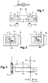
- Such a known binocular display is represented on the figure 1 .
- the optical imagers 1, 2 are intended to shape the optical beams from an electronic and optical system for generating light beams from a miniature screen 3, 4.
- Each optical imager directs the optical beams to each eye of the carrier 01, 02 to allow the visualization of the information content.
- an electronic signal carrying information is brought to each miniature screen by a cable.
- the miniature screen illuminated by a downlight, generates a pixelated image corresponding to the information.
- a "KOPIN Cyberdisplay 320 color" screen generating images of 320 x 240 pixels and a size of 4.8 mm x 3.6 mm.
- the screens are referenced by means of a mechanical interface with respect to the optical imagers.
- a protective shell protects all or part of the whole.
- a step consisting in physically moving the miniature screens 3, 4 perpendicularly to the optical axis A1, A2 of the imagers optical, so to move at least one of the virtual images correspondingly and thus bring the superposition of the right and left images.
- the known alignment principle consists of fixing the first screen, for example the left 3 with respect to the left-hand imager 1, typically by gluing, then moving the right-hand screen 4 perpendicularly to the optical axis A2 of FIG. the right imager to bring the right image into coincidence with the left image and this makes it possible to block it in the aligned position by a gluing.
- the miniature screens have an active surface larger than said determined surface of the transmitted image and the display adjustment method then consists of electronically moving the image transmitted on the screen, in order to obtain a set position of this image in this screen corresponding to a superposition of the two virtual images.
- the binocular display comprises an imager integrated in each lens of a pair of glasses and receiving the optical beams of a beam generating device comprising a said miniature screen.
- the generating devices each containing a portion of the optical system and a screen can be as small as possible since it is no longer necessary to add a mechanical system for transverse adjustment of the position of the miniature screen.
- the advantage of achieving an electronic displacement of the image is to be able to achieve with the hood closed and therefore at the last moment, in a low-binding environment because not requiring any care of cleanliness or tools.
- Another advantage is not having to physically touch the system during adjustment and thus reduce errors and increase the convergence speed of the melting adjustment.
- the merge setting is thus more reliable.
- the invention therefore proposes a miniature screen driver of a binocular display comprising all the features recited in claim 1.
- Such a driver or control box forms an interface between a computer transmitting the compensation parameters defined by means of an adjustment bench and the miniature screens of the display, in a setting situation at an installer, and also an interface between an image source and the display, in reading situation by a user.
- This driver therefore makes it easy to modify the setting of the miniature screens, according to the wearer, in order to obtain a perfect alignment of the virtual images.
- the pilot comprises a compensation circuit and a displacement circuit for displaying an image transmitted by said source to the display circuit of said screen.
- said compensation circuit comprises a CPU providing a compensation management function consisting of storing said compensation parameters as well as parameters of formulas for calculating these compensation parameters.
- said CPU provides error control and correction of said compensation parameters.
- Said CPU can also provide a video loopback management function of generating a fixed test image previously stored in the driver by said computer.
- the storage of the compensation parameters associates them with a user identifier in a personalized compensation profile.
- said displacement circuit comprises a GPU providing an image processing function performing continuously and in real time the electronic displacement of the image.
- Said image processing function may consist of an image rotation specific to each miniature screen and an image translation specific to each miniature screen.
- Said image processing function may also include an image de-interlacing common to both miniature screens.
- the driver according to the invention comprises a man-machine interface allowing a user to select a personalized compensation profile.
- the human machine interface may allow a user to select a deinterlace mode.
- this method comprises a first calibration step of storing in memory the calibration coordinates of the center of a target with respect to the optical axis of each camera.
- Two cameras can be used and the method may comprise a prior step of convergence of the optical axes of said cameras on said common target.
- Said device may comprise a control computer of an alignment bench intended to be connected to said driver.
- the figure 2 illustrates the general concept of the invention.
- a binocular-type display comprises, for each eye of the wearer, an optical imager 1, 2 for shaping optical beams corresponding to a determined surface image IE1, IE2 emitted from the fixed miniature screens 3, 4 , each provided with a display driver connected for example by an address sheet N1, N2 and directing them towards each eye of the carrier O1, O2 to enable the visualization of an information content contained in a virtual image I1, I2.
- At least one of said miniature screens, and preferably both screens 3, 4 have an active area S1, S2 larger than the determined area of the transmitted image IE1, IE2.
- an active area screen equal to 690 x 530 pixels, or 50 pixels more around the determined surface of the image.
- the transmitted image IE1 by the left screen 3 is centered on the active surface S1 of the screen 3 and the transmitted image IE2 by the right screen 4 is shifted from the central position.
- the adjustment method according to the invention of such a display consists of moving the transmitted image IE in the screen, in order to obtain a set position of this image in this screen corresponding to a superposition of the two virtual images right and left I1, I2.
- optical axis A'1 corresponding to an image emitted in the center of the miniature screen 3.
- these optical beams are directed to the eye 01 of the carrier and a virtual image is visible centered on the axis B'1.
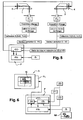
- the figure 4 represents an adjustment bench for the implementation of the method according to the invention.
- An alignment bench 10 is calibrated beforehand by converging the optical axes of the right C1 and left C2 cameras on the convergence target CI. This adjustment is obtained by means of appropriate opto-mechanical devices and the acquisition of the image by the cameras.
- the bench and its settings are designed so that the final adjustment sensitivity is less than or equal to 1 pixel.
- a computer stores in memory the coordinates (XcG, YcG) and (XcD, YcD). They then designate the points to which the binocular setting should converge.
- An alternative principle may use only one camera that is translated between the two right and left positions. The same camera is then translated with a known value of displacement between the two right and left positions.
- An alternative principle may use only one camera and a system of calibrated prisms and mirrors combining the right and left images into one.
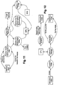
- the figure 5 represents this alignment algorithm protocol.
- the mechanical construction of the alignment bench and the mounting of the display ensure that the X and Y axes of the miniature screens 3, 4 and detectors of the cameras C1, C2 are respectively aligned, considering an unfolded optical axis.
- an image fed by an image source S and serving as an alignment target is displayed on the right and left screens 3, 4.
- its shape is studied for this purpose, it is for example a cross passing through the center of the image.
- VD - XiG - XCG .
- R ⁇ BOY WUT YIG - YCG •
- RYG - XID - XCD .
- R ⁇ D Yid - YCD • Ryd
- RxG and RxD are the magnification ratios of one pixel of the miniature screen on a pixel of the camera detector along the X axis for the left and right cameras respectively.
- the sign of these two quantities may be different, especially in the case where the optical system of the binocular glasses, namely the imager 1, 2, contains mirrors.
- R can also be evaluated theoretically or practically by measuring the transverse magnification GYimageur of the miniature screen conjugation - virtual image through the imager and the transverse magnification GYcam of the virtual image-CCD conjugation camera through the lens of the camera.
- R Pitch ⁇ D / GYpipe • GYcam • PitchCCD
- Pitch ⁇ D is the size of the pixel of the miniature screen
- PitchCCD is the size of the camera detector.
- These vectors VD and VG are then directed to the pilot P of the miniature screens 3, 4 and more particularly to specific circuits dedicated to the compensation of the right-left alignment gap CC.
- These circuits are two in number, one for each miniature screen, and their purpose is on the one hand to store the values of the correction vectors VD and VG respectively and on the other hand to transform the output signal of the display circuits. PA primary according to these correction vectors.
- Each primary display circuit or driver PA addresses the pixels of the screen from the image data to be displayed and redirects its output data to the DC compensation circuit.
- the figure 6 represents the hardware architecture for the implementation of this protocol.
- a control computer of the alignment bank 20 is connected to a transfer unit of the correction vector 21 to a memory unit 23 of the driver P of the screen 3. It is also connected to a memory control channel 22 comprising a reset unit for resetting the correction vector stored in the memory unit 23 of the compensation circuit CC and an adder for adding the value of the correction vector to the value stored in the same memory unit 23.
- a translation circuit 24 of the image display translates an IM image transmitted by the source S to the display driver or circuit PA, the value of the correction vector stored in the memory unit 23. transmits the IE translated image to the thumbnail screen 3.
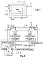
- the figure 7 is a front view of a miniature screen according to the invention.
- This adjustment range depends on the opto-mechanical tolerance budget of the system for the fusion between the two images and on the characteristics of the optical image enlarging system, for example the imager 1.
- np Delta / Pitch_ ⁇ D when the run of the screen is expressed as +/- delta.
- the value of Delta and / or that of Pitch, and hence that of Np along the X axis may differ from that of the Y axis of the miniature screen.
- the screen thus has the active surface geometry represented on the figure 7 or :
- Lf NLF • Pitch_ ⁇ D
- NHf and NLf being the dimensions of the format to be displayed in pixels, for example respectively 480 and 640 if it is a VGA format.
- the pixels are addressed so that they are opaque and black.
- EFL is the effective focus and Pitch_ ⁇ D the pixel size.
- EFL 20 mm
- alpha 0.5 ⁇
- Pitch_ ⁇ D 10 ⁇ m
- a capability of the system C 9, which is a good result.
- the figure 8 represents the same alignment algorithm protocol as previously illustrated on the figure 5 , but applied to another type of binocular display.
- lens relates in particular to a glass, corrector or not, intended to be mounted in a spectacle frame.
- An ophthalmic eyeglass lens has traditional features such as vision correction, anti-glare, antifouling, anti-scratch, for example.
- the invention can also be applied to a binocular display with an imager 1, 2 integrated in each lens LG, LD of a pair of ophthalmic spectacles, receiving the optical beam of a beam generating device GG, GD comprising a screen miniature 3, 4 and a mirror and lens type processing arrangement. It is then the mount M which satisfies the mechanical requirements of the method of maintaining the alignment of the binocular display.
- the bench used is similar to the previous one with the only difference that it is possible to vary the interpupillary distance between the cameras C1, C2, that is to say, adjust the distance between these two cameras.
- a set of data (Xc, Yc) f (interpupillary half-distance) is stored in memory in the control computer of the alignment bench for each right and left side at the end of the bench calibration.
- each GD and GG left generation device having its own alignment adjustment value for a given interpupillary distance of the carrier with a specific correction vector stored in memory.
- the range of electronic displacement of the image on the screen is calculated according to the same principle as above: all the mechanical and optical variations of the system are tolerated.
- the electronic displacement of the image compensates for them, and the retention in memory of the correction value in a unit of memory makes it possible to ensure that the adjustment is correct for the wearer at each use.
- control and error correction system can be added to the memory unit. Indeed, these adjustment data are very important for comfort and visual health.
- control circuits of the binocular glasses are provided with either a secondary energy source, for example a battery secondary, to maintain the information stored in active memory, or bistable memory components.
- a secondary energy source for example a battery secondary
- any device known to those skilled in the art to maintain information in memory during a power off can be used, for example long-life lithium type batteries or ROMs, bistable or other, do not not requiring electrical power to maintain their condition
- the invention relates in particular to the pilot P which has already been discussed previously.
- This driver is represented on the Figures 9 and 10 . It is arranged in a housing 30 and provided with a first connection P1 for communication with a computer O, for example a female USB socket intended to receive a corresponding USB connection C, a second data input connection P2 from an image source S, for example a female base intended to accommodate an external analog or digital video source and a third connection P3 to said screens, right and left, of the display A.
- the computer O may be preferably the control computer of the alignment bench 20 or another computer having in memory the data of the control computer of the alignment bench 20.
- connection of the computer, the image source and the display with the driver can be done by cable or without cable, by a "wireless" type connection.
- This housing has for example the shape of a rectangular parallelepiped, for example of maximum dimensions 90 mm in length, 55 mm in width and 10 mm in height. Its maximum weight can be 200 g.
- the driver may also alternatively be integrated into the housing of an integral image generation arrangement, removably or not, a display A.
- the driver also includes an actuator arrangement 31 of the multi-directional joystick type that allows the user to configure the driver functionality.
- a button is provided on the housing of the P driver to lock this actuation arrangement, to prevent any undesirable action.
- This actuating arrangement 31 is part of a man-machine interface allowing a user to select a custom compensation profile.
- This human machine interface can also allow a user to select a deinterlace mode.
- the first connection P1 also allows the driver to be connected to a DC or AC power source via a suitable USB power adapter a1, a2.
- the driver comprises a DC compensation circuit and a displacement circuit 24 for displaying an IM image transmitted by said source S to the display circuit PA of said screen.
- the USB communication management function enables communication with the computer O. It provides it with the various driver information descriptors that are contained in the executable code of the firmware of the CPU function, and sets up an application protocol.
- two bidirectional USB communication channels a control channel that allows the computer to configure and inspect driver functions, and a mass transfer channel that is dedicated primarily to image transfers between the computer and the driver.
- the file management function makes it possible to store files in flash memories, to read images stored in these memories, to search for files stored in these memories and to delete files stored in these memories.
- the Video Loopback Management feature allows you to test the entire video acquisition, processing, and video generation chain of the driver in the absence of an external video signal. It consists in generating a video signal with a test still image and injecting it upstream of the video acquisition chain via a "Mux Video" multiplexer. It develops the control of this multiplexer. It ensures the loading of this test image transmitted by the computer, stores it in a memory ROM of the pilot, the repatriation and makes it read by the flash memories, via the management of files.
- the electronic compensation management function retrieves and reads the data from a file containing electronic compensation parameter data and formula parameters for recalculating the values of the compensation vectors, thereby enabling a control of reliable error on the contents of the file, stored in the flash memories, via file management.
- Storing compensation settings associates a user ID with a custom compensation profile.
- this function systematically performs the initialization of the system a corrective error check on the contents of this file by default.
- the file When preparing the display, the file is redundant and copied into two ORD and BRD flash memories via the USB bus.
- the electronic compensation management function then transmits to a GPU function ("Graphical Processing Unit") the data necessary to process the video, from the valid compensation parameters.
- a GPU function Graphics Processing Unit
- the driver therefore comprises a multiplexer "Mux Video" already mentioned that performs an analog multiplexing between the video input signal from the P2 connection and the video loopback signal generated by a video encoder.
- the video signal resulting from the multiplexing is transmitted to a video decoder. Multiplexing control is developed by the CPU.
- the driver also includes this video decoder that acquires the analog output video signal of the multiplexer, and converts this signal into a standard digital video format that can be processed by the GPU.
- the video decoder automatically switches between PAL and NTSC modes, depending on the nature of the input video signal.
- the video decoding function does not exist.
- the GPU then directly processes the digital format transmitted by the multiplexer.
- the digital formats are not yet very standardized, however, it is considered in the following description that it is an analog signal that is received from the information source S.
- the GPU continuously detects the presence of a valid video signal at the output of a video decoder. If there is no signal or the video signal is invalid, a "NO SIGNAL" message is displayed on a black background in the center of the thumbnail screens.
- the GPU also warns the CPU as soon as it detects or loses a valid video signal, so that the CPU can instantly refresh the values accordingly.
- the video acquisition function realizes in real time the acquisition of the digital video signal coming from the output of the decoder A / N of the video decoder.
- the acquisition task is to extract the image data from the video signal and prepare it for the CPU-related image processing function.
- the image processing function performs continuously and in real time the electronic compensation of the display by the method of electronic displacement of the video image on the active surfaces of the miniature screens.
- Electronically compensated optical correction is to continuously apply in real time on each video image acquired by the video acquisition function, a separate image processing for each left and right video channel. The result of the processing is transmitted to the video generation function for sending to the graphic controllers.
- the left and right video channels undergo the same image processing algorithm, but the parameters of the algorithm are specific to each video channel.
- Electronic compensation is activated automatically after the driver self test phase.
- the electronic compensation performed by the image processing function can be activated or inhibited.
- the electronic compensation is inhibited, only the operations of rotation and translation are deactivated: these two operations are then put in bypass mode, and the video image sent out is the resultant of the centering operation.
- Electronic compensation is automatically activated by default as soon as the power is turned on.
- streak-like defects may appear in the image if the video has been TV-interlaced (at the source, or during post-encoding ) and was not deinterlaced later.
- the driver can integrate an advanced deinterlace functionality, allowing to switch from interlaced video mode to progressive video mode by correcting losses due to TV interleaving.
- the translation and rotation parameters are expressed in absolute relative to the reference position of the reduced useful video image, which corresponds to the position for which the useful video image is centered. in the active surface of the thumbnail screen after definition reduction.
- the useful video image is systematically centered in the work surface before undergoing the rotation and translation operations specific to each video channel.
- the image processing function compensates for angular defects between the left and right images as necessary by tilting the useful video image on the active surface of the miniature screens.
- the inclination of the useful image is defined in the orthonormal coordinate system (Ox, Oy) of the working surface by an affine rotation of center O and angle ⁇ .
- the rotation operation is distinct to each video channel.
- the parameters of the rotation are stored in the files.
- the image processing function After the eventual rotation operation, the image processing function performs alignment if necessary by moving the useful video image on the active surface of the miniature screens horizontally and / or vertically.
- the parameters of the translation are stored in the files.
- the video generation function encodes in real time Square Pixel format the left and right video images generated by the image processing function, and transmits the video signals from the encoding to the graphics controllers of a VGA controller.
- the pattern generation feature generates a VGA (640p (I) x 480p (h)) static image in a digital video format compatible with the video encoder.
- the pilot has three flash memories, some of which have already been mentioned, the Flash memories ORD ("Original Redundant Drive”) and BRD ("Backup Redundant Drive”) which are redundant memories containing among others the system configuration file and the files already mentioned, and a Mass Storage Drive (MSD) flash memory which is a mass storage memory containing among other things the test patterns used for the video loopback function.
- the Flash memories ORD Olinal Redundant Drive
- BRD Backup Redundant Drive
- MSD Mass Storage Drive
- the driver also includes a power function that produces the power signals necessary for the electronic functions of the driver and manages the electric charging of a battery.
- the power supply provided by the USB bus and represented on the figure 10 is mainly used for the electrical recharging in situ of the battery of the pilot, that is to say without having the need to open the case and extract the battery.
- the figure 13 is an electronic synoptic diagram of the driver P according to the invention connected to a display A.
- connection P1 to a computer O or 20 associated with its USB interface
- second connection P2 data input from a source of images S
- third connection P3 to said screens, right 4 and left 3, of the display A.
- image source S can be separated from the driver P as shown here, but it can also be integrated into the electronic architecture of the driver and be contained in the same housing.
- the decoder In the case where the video decoder is not physically integrated into the CPU, as shown here, the decoder must be configurable by I2C protocol via an I2C network bus arbitrated by the function I "I2C interface".
- the mass storage memory containing, among other things, the test patterns is interfaced by a "UART SPI" interface via a fast bus of the SPI type.
Landscapes
- Physics & Mathematics (AREA)
- Engineering & Computer Science (AREA)
- Multimedia (AREA)
- Signal Processing (AREA)
- General Physics & Mathematics (AREA)
- Optics & Photonics (AREA)
- Control Of Indicators Other Than Cathode Ray Tubes (AREA)
- Devices For Indicating Variable Information By Combining Individual Elements (AREA)
Applications Claiming Priority (2)
| Application Number | Priority Date | Filing Date | Title |
|---|---|---|---|
| FR0651481A FR2900475B1 (fr) | 2006-04-26 | 2006-04-26 | Afficheur comportant une paire de lunettes de type binoculaire et avec un dispositif de reglage de l'image |
| PCT/FR2007/051177 WO2007125257A1 (fr) | 2006-04-26 | 2007-04-26 | Pilote pour afficheur comportant une paire de lunettes de type binoculaire |
Publications (2)
| Publication Number | Publication Date |
|---|---|
| EP2010955A1 EP2010955A1 (fr) | 2009-01-07 |
| EP2010955B1 true EP2010955B1 (fr) | 2016-08-31 |
Family
ID=37434363
Family Applications (1)
| Application Number | Title | Priority Date | Filing Date |
|---|---|---|---|
| EP07731950.7A Active EP2010955B1 (fr) | 2006-04-26 | 2007-04-26 | Pilote pour afficheur comportant une paire de lunettes de type binoculaire |
Country Status (5)
| Country | Link |
|---|---|
| US (1) | US20100289880A1 (ja) |
| EP (1) | EP2010955B1 (ja) |
| JP (1) | JP5067701B2 (ja) |
| FR (1) | FR2900475B1 (ja) |
| WO (1) | WO2007125257A1 (ja) |
Families Citing this family (17)
| Publication number | Priority date | Publication date | Assignee | Title |
|---|---|---|---|---|
| FR2906899B1 (fr) * | 2006-10-05 | 2009-01-16 | Essilor Int | Dispositif d'affichage pour la visualisation stereoscopique. |
| US20100259655A1 (en) * | 2007-11-01 | 2010-10-14 | Konica Minolta Holdings, Inc. | Imaging device |
| EP2376968B1 (fr) * | 2008-12-09 | 2013-01-16 | Delphi Technologies, Inc. | Dispositif diffractif d'affichage tête haute muni d'un dispositif de réglage de la position de l'image virtuelle. |
| US8717392B2 (en) * | 2009-06-02 | 2014-05-06 | Nokia Corporation | Apparatus for enabling users to view images, methods and computer readable storage mediums |
| FR2947921B1 (fr) | 2009-07-10 | 2011-11-04 | Essilor Int | Procede de reglage d'un afficheur de type binoculaire comportant une paire de lunettes et afficheur pour la mise en oeuvre de ce procede |
| US9304319B2 (en) | 2010-11-18 | 2016-04-05 | Microsoft Technology Licensing, Llc | Automatic focus improvement for augmented reality displays |
| EP2499965A1 (en) | 2011-03-15 | 2012-09-19 | Universite Paris-Sud (Paris 11) | Method of providing a person with spatial orientation information |
| CA2750287C (en) | 2011-08-29 | 2012-07-03 | Microsoft Corporation | Gaze detection in a see-through, near-eye, mixed reality display |
| US9025252B2 (en) * | 2011-08-30 | 2015-05-05 | Microsoft Technology Licensing, Llc | Adjustment of a mixed reality display for inter-pupillary distance alignment |
| US9213163B2 (en) * | 2011-08-30 | 2015-12-15 | Microsoft Technology Licensing, Llc | Aligning inter-pupillary distance in a near-eye display system |
| EP2751609B1 (en) | 2011-08-30 | 2017-08-16 | Microsoft Technology Licensing, LLC | Head mounted display with iris scan profiling |
| KR102309257B1 (ko) * | 2013-09-04 | 2021-10-06 | 에씰로 앙터나시오날 | 증강 현실을 위한 방법 및 시스템 |
| US10424295B2 (en) | 2016-02-03 | 2019-09-24 | Disney Enterprises, Inc. | Calibration of virtual image displays |
| US20170353714A1 (en) * | 2016-06-06 | 2017-12-07 | Navid Poulad | Self-calibrating display system |
| EP3318915B1 (en) * | 2016-11-04 | 2020-04-22 | Essilor International | Method for determining an optical performance of a head mounted display device |
| JP6932501B2 (ja) * | 2016-12-22 | 2021-09-08 | キヤノン株式会社 | 画像表示装置 |
| EP3582077A1 (en) * | 2018-06-13 | 2019-12-18 | Tobii AB | Eye tracking device and method for manufacturing an eye tracking device |
Family Cites Families (17)
| Publication number | Priority date | Publication date | Assignee | Title |
|---|---|---|---|---|
| JP3676391B2 (ja) * | 1994-04-27 | 2005-07-27 | オリンパス株式会社 | 頭部装着式映像表示装置 |
| US5579026A (en) * | 1993-05-14 | 1996-11-26 | Olympus Optical Co., Ltd. | Image display apparatus of head mounted type |
| JPH0772446A (ja) * | 1993-09-01 | 1995-03-17 | Sharp Corp | 表示システム |
| JP3771964B2 (ja) * | 1996-03-12 | 2006-05-10 | オリンパス株式会社 | 立体映像ディスプレイ装置 |
| JPH09304729A (ja) * | 1996-05-15 | 1997-11-28 | Sony Corp | 光学視覚装置 |
| JPH09322199A (ja) * | 1996-05-29 | 1997-12-12 | Olympus Optical Co Ltd | 立体映像ディスプレイ装置 |
| US5731902A (en) * | 1996-08-19 | 1998-03-24 | Delco Electronics Corporation | Head-up display combiner binocular test fixture |
| US5974348A (en) * | 1996-12-13 | 1999-10-26 | Rocks; James K. | System and method for performing mobile robotic work operations |
| US6191809B1 (en) * | 1998-01-15 | 2001-02-20 | Vista Medical Technologies, Inc. | Method and apparatus for aligning stereo images |
| JPH11282440A (ja) * | 1998-03-26 | 1999-10-15 | Sony Corp | 展示物説明システム |
| FR2780517A1 (fr) * | 1998-06-24 | 1999-12-31 | Rachid Hamdani | Dispositif de visualisation stereoscopique laser |
| JP2001255858A (ja) * | 2000-01-06 | 2001-09-21 | Victor Co Of Japan Ltd | 液晶表示システム |
| JP4610799B2 (ja) * | 2001-06-25 | 2011-01-12 | オリンパス株式会社 | 立体観察システム、及び内視鏡装置 |
| JP2003098471A (ja) * | 2001-09-25 | 2003-04-03 | Olympus Optical Co Ltd | 頭部装着型映像表示装置 |
| WO2003079272A1 (en) * | 2002-03-15 | 2003-09-25 | University Of Washington | Materials and methods for simulating focal shifts in viewers using large depth of focus displays |
| JP4707081B2 (ja) * | 2002-06-05 | 2011-06-22 | ソニー株式会社 | 撮像装置および撮像方法 |
| JP2005128301A (ja) * | 2003-10-24 | 2005-05-19 | Shimadzu Corp | 頭部装着型表示システム |
-
2006
- 2006-04-26 FR FR0651481A patent/FR2900475B1/fr active Active
-
2007
- 2007-04-26 US US12/225,363 patent/US20100289880A1/en not_active Abandoned
- 2007-04-26 WO PCT/FR2007/051177 patent/WO2007125257A1/fr active Application Filing
- 2007-04-26 JP JP2009507133A patent/JP5067701B2/ja active Active
- 2007-04-26 EP EP07731950.7A patent/EP2010955B1/fr active Active
Also Published As
| Publication number | Publication date |
|---|---|
| WO2007125257A1 (fr) | 2007-11-08 |
| US20100289880A1 (en) | 2010-11-18 |
| JP2009536477A (ja) | 2009-10-08 |
| EP2010955A1 (fr) | 2009-01-07 |
| JP5067701B2 (ja) | 2012-11-07 |
| FR2900475A1 (fr) | 2007-11-02 |
| FR2900475B1 (fr) | 2008-10-31 |
Similar Documents
| Publication | Publication Date | Title |
|---|---|---|
| EP2010955B1 (fr) | Pilote pour afficheur comportant une paire de lunettes de type binoculaire | |
| JP7478773B2 (ja) | ウェアラブルヘッドアップディスプレイにおけるアイボックス拡張のためのシステム、機器、及び方法 | |
| US11762209B2 (en) | Modular and detachable wearable devices for AR/VR/MR | |
| EP2212736B1 (fr) | Dispositif de surveillance croisée pour afficheurs dits tête haute | |
| EP2070338B1 (fr) | Dispositif d'affichage pour la visualisation stéréoscopique | |
| US11178380B2 (en) | Converting a monocular camera into a binocular stereo camera | |
| JP5827988B2 (ja) | 立体画像撮像装置 | |
| US9237338B1 (en) | Apparatus for image display with multi-focal length progressive lens or multiple discrete lenses each having different fixed focal lengths or a variable focal length | |
| CN111432201A (zh) | 显示系统及其控制方法、信息处理装置和记录介质 | |
| US11516457B2 (en) | Switchable fringe pattern illuminator | |
| EP2469868B1 (fr) | Procédé de correction de l'hyperstéréoscopie et système de visualisation de casque associé | |
| US20240073392A1 (en) | Optical waveguide combiner systems and methods | |
| FR2811849A1 (fr) | Camera stereoscopique munie de moyens pour faciliter le reglage de ses parametres opto-mecaniques | |
| US20230119935A1 (en) | Gaze-guided image capture | |
| TW202238222A (zh) | 用於擴增實境及虛擬實境裝置的反向穿透式眼鏡 | |
| WO2017117039A1 (en) | Omnidirectional catadioptric lens with odd aspheric contour or multi-lens | |
| EP4202544B1 (fr) | Viseur dual pour dispositif d'observation | |
| GB2436409A (en) | Camera with reflector for forming images on different sensor portions | |
| TW202235961A (zh) | 波導顯示器中的光重定向特徵 | |
| JP2615363B2 (ja) | 立体画像装置 | |
| FR2616923A1 (fr) | Dispositif modulaire pour la prise de vues stereoscopique |
Legal Events
| Date | Code | Title | Description |
|---|---|---|---|
| PUAI | Public reference made under article 153(3) epc to a published international application that has entered the european phase |
Free format text: ORIGINAL CODE: 0009012 |
|
| 17P | Request for examination filed |
Effective date: 20080916 |
|
| AK | Designated contracting states |
Kind code of ref document: A1 Designated state(s): AT BE BG CH CY CZ DE DK EE ES FI FR GB GR HU IE IS IT LI LT LU LV MC MT NL PL PT RO SE SI SK TR |
|
| AX | Request for extension of the european patent |
Extension state: AL BA HR MK RS |
|
| DAX | Request for extension of the european patent (deleted) | ||
| 17Q | First examination report despatched |
Effective date: 20150427 |
|
| GRAP | Despatch of communication of intention to grant a patent |
Free format text: ORIGINAL CODE: EPIDOSNIGR1 |
|
| INTG | Intention to grant announced |
Effective date: 20160331 |
|
| GRAS | Grant fee paid |
Free format text: ORIGINAL CODE: EPIDOSNIGR3 |
|
| GRAA | (expected) grant |
Free format text: ORIGINAL CODE: 0009210 |
|
| AK | Designated contracting states |
Kind code of ref document: B1 Designated state(s): AT BE BG CH CY CZ DE DK EE ES FI FR GB GR HU IE IS IT LI LT LU LV MC MT NL PL PT RO SE SI SK TR |
|
| REG | Reference to a national code |
Ref country code: CH Ref legal event code: EP Ref country code: GB Ref legal event code: FG4D Free format text: NOT ENGLISH |
|
| REG | Reference to a national code |
Ref country code: IE Ref legal event code: FG4D Free format text: LANGUAGE OF EP DOCUMENT: FRENCH |
|
| REG | Reference to a national code |
Ref country code: DE Ref legal event code: R096 Ref document number: 602007047718 Country of ref document: DE |
|
| REG | Reference to a national code |
Ref country code: AT Ref legal event code: REF Ref document number: 825471 Country of ref document: AT Kind code of ref document: T Effective date: 20161015 |
|
| REG | Reference to a national code |
Ref country code: LT Ref legal event code: MG4D |
|
| REG | Reference to a national code |
Ref country code: NL Ref legal event code: MP Effective date: 20160831 |
|
| REG | Reference to a national code |
Ref country code: AT Ref legal event code: MK05 Ref document number: 825471 Country of ref document: AT Kind code of ref document: T Effective date: 20160831 |
|
| PG25 | Lapsed in a contracting state [announced via postgrant information from national office to epo] |
Ref country code: FI Free format text: LAPSE BECAUSE OF FAILURE TO SUBMIT A TRANSLATION OF THE DESCRIPTION OR TO PAY THE FEE WITHIN THE PRESCRIBED TIME-LIMIT Effective date: 20160831 Ref country code: LT Free format text: LAPSE BECAUSE OF FAILURE TO SUBMIT A TRANSLATION OF THE DESCRIPTION OR TO PAY THE FEE WITHIN THE PRESCRIBED TIME-LIMIT Effective date: 20160831 |
|
| PG25 | Lapsed in a contracting state [announced via postgrant information from national office to epo] |
Ref country code: LV Free format text: LAPSE BECAUSE OF FAILURE TO SUBMIT A TRANSLATION OF THE DESCRIPTION OR TO PAY THE FEE WITHIN THE PRESCRIBED TIME-LIMIT Effective date: 20160831 Ref country code: GR Free format text: LAPSE BECAUSE OF FAILURE TO SUBMIT A TRANSLATION OF THE DESCRIPTION OR TO PAY THE FEE WITHIN THE PRESCRIBED TIME-LIMIT Effective date: 20161201 Ref country code: AT Free format text: LAPSE BECAUSE OF FAILURE TO SUBMIT A TRANSLATION OF THE DESCRIPTION OR TO PAY THE FEE WITHIN THE PRESCRIBED TIME-LIMIT Effective date: 20160831 Ref country code: ES Free format text: LAPSE BECAUSE OF FAILURE TO SUBMIT A TRANSLATION OF THE DESCRIPTION OR TO PAY THE FEE WITHIN THE PRESCRIBED TIME-LIMIT Effective date: 20160831 Ref country code: NL Free format text: LAPSE BECAUSE OF FAILURE TO SUBMIT A TRANSLATION OF THE DESCRIPTION OR TO PAY THE FEE WITHIN THE PRESCRIBED TIME-LIMIT Effective date: 20160831 Ref country code: SE Free format text: LAPSE BECAUSE OF FAILURE TO SUBMIT A TRANSLATION OF THE DESCRIPTION OR TO PAY THE FEE WITHIN THE PRESCRIBED TIME-LIMIT Effective date: 20160831 |
|
| REG | Reference to a national code |
Ref country code: FR Ref legal event code: PLFP Year of fee payment: 11 |
|
| PG25 | Lapsed in a contracting state [announced via postgrant information from national office to epo] |
Ref country code: EE Free format text: LAPSE BECAUSE OF FAILURE TO SUBMIT A TRANSLATION OF THE DESCRIPTION OR TO PAY THE FEE WITHIN THE PRESCRIBED TIME-LIMIT Effective date: 20160831 Ref country code: RO Free format text: LAPSE BECAUSE OF FAILURE TO SUBMIT A TRANSLATION OF THE DESCRIPTION OR TO PAY THE FEE WITHIN THE PRESCRIBED TIME-LIMIT Effective date: 20160831 |
|
| PG25 | Lapsed in a contracting state [announced via postgrant information from national office to epo] |
Ref country code: CZ Free format text: LAPSE BECAUSE OF FAILURE TO SUBMIT A TRANSLATION OF THE DESCRIPTION OR TO PAY THE FEE WITHIN THE PRESCRIBED TIME-LIMIT Effective date: 20160831 Ref country code: PL Free format text: LAPSE BECAUSE OF FAILURE TO SUBMIT A TRANSLATION OF THE DESCRIPTION OR TO PAY THE FEE WITHIN THE PRESCRIBED TIME-LIMIT Effective date: 20160831 Ref country code: DK Free format text: LAPSE BECAUSE OF FAILURE TO SUBMIT A TRANSLATION OF THE DESCRIPTION OR TO PAY THE FEE WITHIN THE PRESCRIBED TIME-LIMIT Effective date: 20160831 Ref country code: PT Free format text: LAPSE BECAUSE OF FAILURE TO SUBMIT A TRANSLATION OF THE DESCRIPTION OR TO PAY THE FEE WITHIN THE PRESCRIBED TIME-LIMIT Effective date: 20170102 Ref country code: BG Free format text: LAPSE BECAUSE OF FAILURE TO SUBMIT A TRANSLATION OF THE DESCRIPTION OR TO PAY THE FEE WITHIN THE PRESCRIBED TIME-LIMIT Effective date: 20161130 Ref country code: SK Free format text: LAPSE BECAUSE OF FAILURE TO SUBMIT A TRANSLATION OF THE DESCRIPTION OR TO PAY THE FEE WITHIN THE PRESCRIBED TIME-LIMIT Effective date: 20160831 |
|
| REG | Reference to a national code |
Ref country code: DE Ref legal event code: R097 Ref document number: 602007047718 Country of ref document: DE |
|
| PG25 | Lapsed in a contracting state [announced via postgrant information from national office to epo] |
Ref country code: IT Free format text: LAPSE BECAUSE OF FAILURE TO SUBMIT A TRANSLATION OF THE DESCRIPTION OR TO PAY THE FEE WITHIN THE PRESCRIBED TIME-LIMIT Effective date: 20160831 |
|
| PLBE | No opposition filed within time limit |
Free format text: ORIGINAL CODE: 0009261 |
|
| STAA | Information on the status of an ep patent application or granted ep patent |
Free format text: STATUS: NO OPPOSITION FILED WITHIN TIME LIMIT |
|
| 26N | No opposition filed |
Effective date: 20170601 |
|
| PG25 | Lapsed in a contracting state [announced via postgrant information from national office to epo] |
Ref country code: SI Free format text: LAPSE BECAUSE OF FAILURE TO SUBMIT A TRANSLATION OF THE DESCRIPTION OR TO PAY THE FEE WITHIN THE PRESCRIBED TIME-LIMIT Effective date: 20160831 |
|
| REG | Reference to a national code |
Ref country code: CH Ref legal event code: PL |
|
| REG | Reference to a national code |
Ref country code: IE Ref legal event code: MM4A |
|
| PG25 | Lapsed in a contracting state [announced via postgrant information from national office to epo] |
Ref country code: MC Free format text: LAPSE BECAUSE OF FAILURE TO SUBMIT A TRANSLATION OF THE DESCRIPTION OR TO PAY THE FEE WITHIN THE PRESCRIBED TIME-LIMIT Effective date: 20160831 |
|
| PG25 | Lapsed in a contracting state [announced via postgrant information from national office to epo] |
Ref country code: CH Free format text: LAPSE BECAUSE OF NON-PAYMENT OF DUE FEES Effective date: 20170430 Ref country code: LU Free format text: LAPSE BECAUSE OF NON-PAYMENT OF DUE FEES Effective date: 20170426 Ref country code: LI Free format text: LAPSE BECAUSE OF NON-PAYMENT OF DUE FEES Effective date: 20170430 |
|
| REG | Reference to a national code |
Ref country code: BE Ref legal event code: MM Effective date: 20170430 |
|
| REG | Reference to a national code |
Ref country code: DE Ref legal event code: R081 Ref document number: 602007047718 Country of ref document: DE Owner name: ESSILOR INTERNATIONAL, FR Free format text: FORMER OWNER: ESSILOR INTERNATIONAL (COMPAGNIE GENERALE D'OPTIQUE), CHARENTON LE PONT, FR |
|
| REG | Reference to a national code |
Ref country code: FR Ref legal event code: PLFP Year of fee payment: 12 |
|
| PG25 | Lapsed in a contracting state [announced via postgrant information from national office to epo] |
Ref country code: IE Free format text: LAPSE BECAUSE OF NON-PAYMENT OF DUE FEES Effective date: 20170426 |
|
| PG25 | Lapsed in a contracting state [announced via postgrant information from national office to epo] |
Ref country code: BE Free format text: LAPSE BECAUSE OF NON-PAYMENT OF DUE FEES Effective date: 20170430 |
|
| REG | Reference to a national code |
Ref country code: GB Ref legal event code: 732E Free format text: REGISTERED BETWEEN 20180517 AND 20180523 |
|
| REG | Reference to a national code |
Ref country code: FR Ref legal event code: TP Owner name: ESSILOR INTERNATIONAL, FR Effective date: 20180601 |
|
| PG25 | Lapsed in a contracting state [announced via postgrant information from national office to epo] |
Ref country code: MT Free format text: LAPSE BECAUSE OF FAILURE TO SUBMIT A TRANSLATION OF THE DESCRIPTION OR TO PAY THE FEE WITHIN THE PRESCRIBED TIME-LIMIT Effective date: 20160831 |
|
| PG25 | Lapsed in a contracting state [announced via postgrant information from national office to epo] |
Ref country code: HU Free format text: LAPSE BECAUSE OF FAILURE TO SUBMIT A TRANSLATION OF THE DESCRIPTION OR TO PAY THE FEE WITHIN THE PRESCRIBED TIME-LIMIT; INVALID AB INITIO Effective date: 20070426 |
|
| PG25 | Lapsed in a contracting state [announced via postgrant information from national office to epo] |
Ref country code: CY Free format text: LAPSE BECAUSE OF NON-PAYMENT OF DUE FEES Effective date: 20160831 |
|
| PG25 | Lapsed in a contracting state [announced via postgrant information from national office to epo] |
Ref country code: TR Free format text: LAPSE BECAUSE OF FAILURE TO SUBMIT A TRANSLATION OF THE DESCRIPTION OR TO PAY THE FEE WITHIN THE PRESCRIBED TIME-LIMIT Effective date: 20160831 |
|
| PG25 | Lapsed in a contracting state [announced via postgrant information from national office to epo] |
Ref country code: IS Free format text: LAPSE BECAUSE OF FAILURE TO SUBMIT A TRANSLATION OF THE DESCRIPTION OR TO PAY THE FEE WITHIN THE PRESCRIBED TIME-LIMIT Effective date: 20161231 |
|
| P01 | Opt-out of the competence of the unified patent court (upc) registered |
Effective date: 20230525 |
|
| PGFP | Annual fee paid to national office [announced via postgrant information from national office to epo] |
Ref country code: FR Payment date: 20230425 Year of fee payment: 17 Ref country code: DE Payment date: 20230427 Year of fee payment: 17 |
|
| PGFP | Annual fee paid to national office [announced via postgrant information from national office to epo] |
Ref country code: GB Payment date: 20230427 Year of fee payment: 17 |