EP2376968B1 - Dispositif diffractif d'affichage tête haute muni d'un dispositif de réglage de la position de l'image virtuelle. - Google Patents
Dispositif diffractif d'affichage tête haute muni d'un dispositif de réglage de la position de l'image virtuelle. Download PDFInfo
- Publication number
- EP2376968B1 EP2376968B1 EP09764867A EP09764867A EP2376968B1 EP 2376968 B1 EP2376968 B1 EP 2376968B1 EP 09764867 A EP09764867 A EP 09764867A EP 09764867 A EP09764867 A EP 09764867A EP 2376968 B1 EP2376968 B1 EP 2376968B1
- Authority
- EP
- European Patent Office
- Prior art keywords
- display
- diffractive
- fact
- head
- display device
- Prior art date
- Legal status (The legal status is an assumption and is not a legal conclusion. Google has not performed a legal analysis and makes no representation as to the accuracy of the status listed.)
- Active
Links
- 239000010410 layer Substances 0.000 claims description 14
- 238000005286 illumination Methods 0.000 claims description 12
- 238000004519 manufacturing process Methods 0.000 claims description 8
- 230000003287 optical effect Effects 0.000 claims description 7
- 238000002347 injection Methods 0.000 claims description 5
- 239000007924 injection Substances 0.000 claims description 5
- 238000004049 embossing Methods 0.000 claims description 4
- 230000002452 interceptive effect Effects 0.000 claims description 3
- 239000004973 liquid crystal related substance Substances 0.000 claims description 3
- 239000002356 single layer Substances 0.000 claims description 3
- 239000011159 matrix material Substances 0.000 description 6
- 238000000034 method Methods 0.000 description 6
- 229920003023 plastic Polymers 0.000 description 6
- 239000004020 conductor Substances 0.000 description 5
- 239000000463 material Substances 0.000 description 5
- 239000000758 substrate Substances 0.000 description 4
- 238000003486 chemical etching Methods 0.000 description 3
- 238000010586 diagram Methods 0.000 description 3
- 229920002120 photoresistant polymer Polymers 0.000 description 3
- 238000007493 shaping process Methods 0.000 description 3
- 239000000126 substance Substances 0.000 description 3
- 239000003086 colorant Substances 0.000 description 2
- 238000000151 deposition Methods 0.000 description 2
- 238000005323 electroforming Methods 0.000 description 2
- 238000005329 nanolithography Methods 0.000 description 2
- 239000000243 solution Substances 0.000 description 2
- 230000005540 biological transmission Effects 0.000 description 1
- 238000009792 diffusion process Methods 0.000 description 1
- 238000006073 displacement reaction Methods 0.000 description 1
- 238000004090 dissolution Methods 0.000 description 1
- 239000013013 elastic material Substances 0.000 description 1
- 230000010354 integration Effects 0.000 description 1
- 238000000465 moulding Methods 0.000 description 1
- 239000007787 solid Substances 0.000 description 1
Images

Classifications
-
- G—PHYSICS
- G02—OPTICS
- G02B—OPTICAL ELEMENTS, SYSTEMS OR APPARATUS
- G02B27/00—Optical systems or apparatus not provided for by any of the groups G02B1/00 - G02B26/00, G02B30/00
- G02B27/01—Head-up displays
- G02B27/0101—Head-up displays characterised by optical features
-
- G—PHYSICS
- G03—PHOTOGRAPHY; CINEMATOGRAPHY; ANALOGOUS TECHNIQUES USING WAVES OTHER THAN OPTICAL WAVES; ELECTROGRAPHY; HOLOGRAPHY
- G03B—APPARATUS OR ARRANGEMENTS FOR TAKING PHOTOGRAPHS OR FOR PROJECTING OR VIEWING THEM; APPARATUS OR ARRANGEMENTS EMPLOYING ANALOGOUS TECHNIQUES USING WAVES OTHER THAN OPTICAL WAVES; ACCESSORIES THEREFOR
- G03B21/00—Projectors or projection-type viewers; Accessories therefor
- G03B21/14—Details
- G03B21/142—Adjusting of projection optics
-
- G—PHYSICS
- G03—PHOTOGRAPHY; CINEMATOGRAPHY; ANALOGOUS TECHNIQUES USING WAVES OTHER THAN OPTICAL WAVES; ELECTROGRAPHY; HOLOGRAPHY
- G03B—APPARATUS OR ARRANGEMENTS FOR TAKING PHOTOGRAPHS OR FOR PROJECTING OR VIEWING THEM; APPARATUS OR ARRANGEMENTS EMPLOYING ANALOGOUS TECHNIQUES USING WAVES OTHER THAN OPTICAL WAVES; ACCESSORIES THEREFOR
- G03B21/00—Projectors or projection-type viewers; Accessories therefor
- G03B21/14—Details
- G03B21/28—Reflectors in projection beam
-
- G—PHYSICS
- G02—OPTICS
- G02B—OPTICAL ELEMENTS, SYSTEMS OR APPARATUS
- G02B27/00—Optical systems or apparatus not provided for by any of the groups G02B1/00 - G02B26/00, G02B30/00
- G02B27/01—Head-up displays
- G02B27/0101—Head-up displays characterised by optical features
- G02B2027/0123—Head-up displays characterised by optical features comprising devices increasing the field of view
-
- G—PHYSICS
- G02—OPTICS
- G02B—OPTICAL ELEMENTS, SYSTEMS OR APPARATUS
- G02B27/00—Optical systems or apparatus not provided for by any of the groups G02B1/00 - G02B26/00, G02B30/00
- G02B27/01—Head-up displays
- G02B27/0149—Head-up displays characterised by mechanical features
- G02B2027/0154—Head-up displays characterised by mechanical features with movable elements
- G02B2027/0159—Head-up displays characterised by mechanical features with movable elements with mechanical means other than scaning means for positioning the whole image
-
- G—PHYSICS
- G03—PHOTOGRAPHY; CINEMATOGRAPHY; ANALOGOUS TECHNIQUES USING WAVES OTHER THAN OPTICAL WAVES; ELECTROGRAPHY; HOLOGRAPHY
- G03B—APPARATUS OR ARRANGEMENTS FOR TAKING PHOTOGRAPHS OR FOR PROJECTING OR VIEWING THEM; APPARATUS OR ARRANGEMENTS EMPLOYING ANALOGOUS TECHNIQUES USING WAVES OTHER THAN OPTICAL WAVES; ACCESSORIES THEREFOR
- G03B21/00—Projectors or projection-type viewers; Accessories therefor
- G03B21/54—Accessories
- G03B21/56—Projection screens
- G03B21/60—Projection screens characterised by the nature of the surface
- G03B21/62—Translucent screens
-
- G—PHYSICS
- G03—PHOTOGRAPHY; CINEMATOGRAPHY; ANALOGOUS TECHNIQUES USING WAVES OTHER THAN OPTICAL WAVES; ELECTROGRAPHY; HOLOGRAPHY
- G03B—APPARATUS OR ARRANGEMENTS FOR TAKING PHOTOGRAPHS OR FOR PROJECTING OR VIEWING THEM; APPARATUS OR ARRANGEMENTS EMPLOYING ANALOGOUS TECHNIQUES USING WAVES OTHER THAN OPTICAL WAVES; ACCESSORIES THEREFOR
- G03B3/00—Focusing arrangements of general interest for cameras, projectors or printers
- G03B3/04—Focusing arrangements of general interest for cameras, projectors or printers adjusting position of image plane without moving lens
Definitions
- the present invention relates to a diffractive head-up display device provided with a device for adjusting the position of the virtual image.
- the virtual image In the High Head Display function, the virtual image is placed in the driver's field of vision, taking into account his ellipse of the eyes and the real scene. However, it is necessary to adjust the position of the virtual image around its nominal position to better adapt to the height of the driver's seat, its size and the vehicle architecture.
- the adjustment of the position of the virtual image is done by rotating one (or more) mirrors around an axis, as this is the case in the document DE 102 2006 017666 .
- This solution is not applicable in the case of a diffractive head-up display device devoid of mirrors and using diffractive components, in particular when the diffractive combiner has been manufactured from a method of recording the diffractive elements which fixes by design the downward viewing angle of the virtual image produced by the display device for an illumination angle of the determined combiner.
- the document EP 0 880 287 describes a projector provided with a system for adjusting the position of the image.
- the document US 2005/0259034 describes a device for adjusting the position of the image in a head-up display.
- the present invention aims to provide a diffractive head-up display device provided with a device for adjusting the position of the virtual image that can operate without having to move or rotate a mirror.
- the present invention proposes a head-up display device comprising a projection unit which produces a light beam directed towards a diffractive combiner arranged to form a virtual image in the field of view of an observer, the unit of projection comprising a light source which produces a projection light beam directed towards a display intended to form a source image transmitted to the diffractive combiner, characterized in that the projection unit comprises a projection mask which is arranged after the display and which is provided with a projection window whose area corresponds generally to the display area of the display, in that the light beam illuminates uniformly at the display a greater area than the display area, and in that the display and the mask are movable in translation along at least one direction generally orthogonal to the axis of the projection light beam, so that the adjustment of the position the virtual image in the field of view of the observer, for example the driver of a vehicle, is obtained by translation of the display and the mask.
- the solution of the invention is based on a translational movement of the display and on a specific projection window.
- FIG 1 schematically shows the interior of a motor vehicle 10 comprising a dashboard 12 and a diffractive head-up display device 14 made in accordance with the teachings of the invention.
- the diffractive head-up display device 14 is arranged on the dashboard 12, close to the windshield 15.
- the diffractive head-up display device 14 comprises a projection unit 16 and a holographic device 18 which is located in the line of sight of the conductor C and which is intended to display operating or driving information of the driver.
- vehicle in the form of virtual images 19 positioned at the front of the windshield 15 in the field of view of the driver C.
- the projection unit 16 is mounted inside a housing 20.
- the housing 20 contains a light source 26, preferably a visible-field laser diode, which produces a light beam F which is shaped by optical shaping elements 28 before being diffused to a display 30 forming the image source.
- the display 30 is for example a liquid crystal screen.
- the optical shaping elements 28 are intended to produce a light beam F of shape adapted to the shape of the display 30 and of section according to the adjustment interval of the virtual image.
- the display 30 is configured to produce source images representing the operating or driving information of the vehicle.
- the display 30 is preferably provided with an optical diffusion layer 32.
- the holographic device 18 is a diffractive combiner operating in reflection.
- the diffractive combiner 18 is arranged in the field of view of the conductor C so that the light beam F coming from the source image refracts through the diffractive combiner 18 to produce a virtual image 19 located at the front of the vehicle
- the diffractive combiner 18 is a transparent part comprising diffractive optical elements.
- the diffractive optical elements are configured to position the holographic virtual image at a predetermined distance to the front of the vehicle and they are also configured for an enlargement function of the source image.
- the diffractive combiner 18 is preferably made of a plastic material by molding / injection or embossing, from a matrix itself made by nano-lithography laser interference.
- the projection unit 16 comprises a projection mask 34 which is arranged after the display 30 and which is provided with a projection window 36 whose area corresponds generally to the area of the projection. display of the display 30, this window moves in translation.
- the light beam F illuminates uniformly, at the level of the display 30, an area A2 larger than the display area A1.
- the display 30 and the mask 34 are movable in translation, relative to the housing 20, in a direction D1 substantially orthogonal to the axis X1 of the projection light beam.
- the direction D1 is here contained in a substantially vertical plane. So, the adjustment of the position of the virtual image 19 in the field of vision of the conductor C is obtained by translating the display 30 and the mask 34 with its projection window 36.
- the value of the angle of vision downward can be varied ⁇ iv .
- the present invention allows the variation of the position of the virtual image 19 by varying the position of the display / mask assembly.
- the display 30 is illuminated by the device 28 for shaping the light beam, diffractive or not.
- the lighting spot obtained on the surface of the display 30 is uniform.
- the height difference L2-L1 between the illumination area A2 and the display area A1 corresponds to the translation length necessary to vary the angle ⁇ and thus the angle ⁇ iv to allow the adjustment of the position of the virtual image 19.
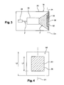
- the figure 5 shows the direction D1 translation of the display 30 in the housing of the projection unit 16.
- the display 30 is translated in the direction D1 while the housing 20 of the projection unit and the combiner 18 stay fixed.
- This translation movement varies the value of the angle ⁇ around a central value ⁇ 0 corresponding to an initial configuration (nominal position of the virtual image) of the diffractive display device 14.
- the body 37 of the mask 34 around the window 36 ensures that only the display 30 is seen by the combiner 18.
- a mechanical system 38 for example a screw-nut system, ensures the displacement in translation of the display 30 around an initial position as represented on the figure 7 .
- the mask 34 is preferably made of elastic material and fixed on the output face of the display 30 so as to mask the unused portion of the illumination spot 39.
- the conductor C can adjust the position of the virtual image 19 through a man / machine interface 40 and an electronic control unit 42 which are provided to control the translation of the display 30 and the mask 34.
- One of the interfering beams is divergent and has a spherical wavefront and the other is a plane wave, their interference generating a variable pitch diffractive grating with contour lines of curved fringes.
- the first step of the process consists in producing a matrix for the subsequent manufacture of molds for mass production.
- This matrix consists of a substrate, made of rigid material, on which is deposited a photoresistant layer sensitive to the wavelength of the laser source used, which is always the same, only the angle between the two beams being modified. one step to another.
- the two light beams from the same source are sent onto the flat surface of the photoresist layer, causing interference fringes on the entire exposed surface.
- the existence of these interferences leads to a variable insolation of the surface of the photosensitive layer, which is then subjected to a chemical substance having the property of dissolving the material according to its degree of insolation.
- the exposure under a plurality of angles leads in this case to the manufacture of a surface-multiplexed network combiner, capable of restoring distinct non-superposed colors, according to an incident beam from a projection device distinguishing areas of different colors.
- the raised surface is deposited a conductive thin layer, subsequently to apply electroforming processes to get a mold.
- the latter is finally used to transform the diffractive structure in relief on a transparent plastic element by means of mass production such as embossing or injection. It is thus possible to obtain a monolayer combiner in transparent plastic, whose diffractive structures are etched on the surface, and are actually diffractive surface gratings in relief.
- the obtaining by chemical etching of a relief on the matrix makes it possible to manage the diffraction efficiency of the final combiner by simply controlling the depth of relief on the surface of the matrix, in particular by varying the chemical etching time.
- the method of the invention finally makes it possible to obtain a transparent plastic combiner in the form of a plastic plane-like plate, one of whose surfaces comprises diffractive structures, which makes it possible to work both with transmission and in reflection, with different diffraction efficiencies.
- the reflection corresponds for example to the integration of a combiner in the windshield.
Description
- La présente invention concerne un dispositif diffractif d'affichage tête haute muni d'un dispositif de réglage de position de l'image virtuelle.
- Dans la fonction Affichage Tête Haute, l'image virtuelle est placée dans le champ de vision du conducteur en tenant compte de son ellipse des yeux et de la scène réelle. Toutefois, il est nécessaire de pouvoir régler la position de l'image virtuelle autour de sa position nominale pour mieux l'adapter à la hauteur du siège du conducteur, à sa taille et à l'architecture du véhicule.
- Dans les dispositifs d'affichage tête haute basés sur l'utilisation d'une série de miroirs, le réglage de la position de l'image virtuelle se fait par rotation d'un (ou de plusieurs) miroirs autour d'un axe, comme c'est le cas dans le document
DE 102 2006 017666 EP 0 880 287 décrit un projecteur pourvu d'un systèm d'ajustement de la position de l'image. - Le document
US 2005/0259034 décrit un dispositif permettant d'ajuster la position de l'image dans un afficheur tête haute. - La présente invention vise à proposer un dispositif diffractif d'affichage tête haute muni d'un dispositif de réglage de la position de l'image virtuelle qui puisse fonctionner sans avoir à déplacer ou faire pivoter un miroir.
- Dans ce but, la présente invention propose un dispositif d'affichage tête haute comportant une unité de projection qui produit un faisceau lumineux dirigé vers un combineur diffractif prévu pour former une image virtuelle dans le champ de vision d'un observateur, l'unité de projection comportant une source lumineuse qui produit un faisceau lumineux de projection dirigé vers un afficheur destiné à former une image source transmise vers le combineur diffractif, caractérisé en ce que l'unité de projection comporte un masque de projection qui est agencé après l'afficheur et qui est muni d'une fenêtre de projection dont l'aire correspond globalement à l'aire d'affichage de l'afficheur, en ce que le faisceau lumineux éclaire de manière uniforme, au niveau de l'afficheur, une aire plus importante que l'aire d'affichage, et en ce que l'afficheur et le masque sont mobiles en translation suivant au moins une direction globalement orthogonale à l'axe du faisceau lumineux de projection, de manière que le réglage de la position de l'image virtuelle dans le champ de vision de l'observateur, par exemple le conducteur d'un véhicule, soit obtenu par translation de l'afficheur et du masque.
- La solution de l'invention est basée sur un mouvement de translation de l'afficheur et sur une fenêtre de projection spécifique.
- Selon d'autres caractéristiques de l'invention :
- le combineur diffractif est réalisé sous la forme d'une plaque transparente munie d'une série d'éléments optiques diffractifs disposés en surface sur une seule couche et dans lequel l'angle de vision vers le bas de l'image virtuelle est fixé par conception lors de la fabrication du combineur diffractif pour un angle d'illumination déterminé ;
- le combineur diffractif est réalisé par injection ou embossage à partir d'un moule, ledit moule étant obtenu à partir de l'enregistrement d'une structure diffractive en relief comportant des franges d'interférence elles-mêmes obtenues par insolation d'une couche photorésistante au moyen de deux faisceaux lumineux interférents ;
- le masque est fixé sur la face de sortie de l'afficheur ;
- l'afficheur est un écran à cristaux liquides ;
- le dispositif diffractif d'affichage comporte un dispositif de commande qui contrôle la position de l'afficheur et du masque.
- D'autres caractéristiques, buts et avantages de l'invention apparaîtront à la lecture de la description détaillée qui va suivre, et en regard des dessins annexés, donnés à titre d'exemple non limitatif et sur lesquels:
- la
figure 1 est vue schématique qui représente l'habitacle d'un véhicule automobile équipé d'un dispositif diffractif d'affichage tête haute conforme aux enseignements de l'invention ; - la
figure 2 est une vue en coupe axiale qui représente schématiquement l'unité de projection et le combineur diffractif équipant le dispositif diffractif d'affichage de lafigure 1 ; - la
figure 3 est une vue en coupe axiale qui représente schématiquement l'unité de projection de lafigure 1 équipée d'un afficheur mobile en translation conformément à l'invention ; - la
figure 4 est un schéma montrant l'aire d'illumination et l'aire d'affichage de l'unité de projection de lafigure 1 ; - la
figure 5 est une vue similaire à celle de lafigure 2 qui montre la direction de translation de l'afficheur de lafigure 3 ; - la
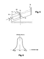
figure 6 est un diagramme illustrant l'efficacité de diffraction du combineur de lafigure 2 en fonction de l'angle d'illumination α ; - la
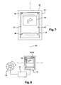
figure 7 est une vue de face qui représente schématiquement la sortie de l'unité de projection de lafigure 1 ; - la
figure 8 est un schéma qui illustre le système de commande de l'unité de projection de lafigure 1 . - Dans la suite de la description, des éléments identiques ou similaires seront désignés par les mêmes références.
- Sur la
figure 1 on a représenté schématiquement l'intérieur d'un véhicule automobile 10 comportant un tableau de bord 12 et un dispositif diffractif d'affichage tête haute 14 réalisé conformément aux enseignements de l'invention. Selon le mode de réalisation représenté, le dispositif diffractif d'affichage tête haute 14 est agencé sur le tableau de bord 12, à proximité du pare-brise 15. - Le dispositif diffractif d'affichage tête haute 14 selon l'invention comporte une unité de projection 16 et un dispositif holographique 18 qui est situé dans l'axe de vision du conducteur C et qui est prévu pour afficher des informations de fonctionnement ou de conduite du véhicule sous la forme d'images virtuelles 19 positionnées à l'avant du pare-brise 15 dans le champ de vision du conducteur C.
- Selon l'exemple de réalisation représenté notamment sur les
figures 2 et3 , l'unité de projection 16 est montée à l'intérieur d'un boîtier 20. Le boîtier 20 contient une source lumineuse 26, de préférence une diode laser émettant dans le domaine visible, qui produit un faisceau lumineux F qui est mis en forme par des éléments optiques de mise en forme 28 avant d'être diffusé vers un afficheur 30 formant l'image source. L'afficheur 30 est par exemple un écran à cristaux liquides. Les éléments optiques de mise en forme 28 visent à produire un faisceau lumineux F de forme adaptée à la forme de l'afficheur 30 et de section fonction de l'intervalle de réglage de l'image virtuelle. L'afficheur 30 est configuré pour produire des images sources représentant les informations de fonctionnement ou de conduite du véhicule. L'afficheur 30 est muni de préférence d'une couche optique de diffusion 32. - Selon le mode de réalisation représenté, le dispositif holographique 18 est un combineur diffractif fonctionnant en réflexion. Le combineur diffractif 18 est agencé dans le champ de vision du conducteur C de manière que le faisceau lumineux F provenant de l'image source se réfracte à travers le combineur diffractif 18 pour produire une image virtuelle 19 située à l'avant du véhicule Avantageusement, le combineur diffractif 18 est une pièce transparente comportant des éléments optiques diffractifs. Les éléments optiques diffractifs sont configurés pour positionner l'image virtuelle 19 holographique à une distance déterminée à l'avant du véhicule et ils sont configurés aussi pour une fonction d'agrandissement de l'image source.
- Le combineur diffractif 18 est réalisé de préférence dans une matière plastique par moulage/injection ou par embossage, à partir d'une matrice elle-même réalisée par nano-lithographie par interférence laser.
- Conformément aux enseignements de l'invention, l'unité de projection 16 comporte un masque de projection 34 qui est agencé après l'afficheur 30 et qui est muni d'une fenêtre de projection 36 dont l'aire correspond globalement à l'aire d'affichage de l'afficheur 30, cette fenêtre se déplace en translation. Comme on peut le voir sur les
figures 3 et 4 , le faisceau lumineux F éclaire de manière uniforme, au niveau de l'afficheur 30, une aire A2 plus importante que l'aire d'affichage A1. Comme représenté sur lafigure 5 , l'afficheur 30 et le masque 34 sont mobiles en translation, par rapport au boîtier 20, suivant une direction D1 globalement orthogonale à l'axe X1 du faisceau lumineux de projection. La direction D1 est ici contenue dans un plan sensiblement vertical. Ainsi, l'ajustement de la position de l'image virtuelle 19 dans le champ de vision du conducteur C est obtenu par translation de l'afficheur 30 et du masque 34 avec sa fenêtre de projection 36. - Comme on peut le voir sur la
figure 2 , l'image virtuelle 19 dans le champ de vision du conducteur C est définie à travers le combineur diffractif 18 par un angle de vision vers le bas β iv et une distance div . La loi de Bragg associe l'angle α d'illumination du combineur 18, correspondant à la position angulaire de l'unité de projection 16, à l'angle de vision vers le bas β iv par l'équation :
Où: - λ: longueur d'onde de la lumière
- d: pas du réseau de diffraction du combineur
- Comme montré précédemment, on peut écrire les équations suivantes :


- Donc en faisant varier la valeur de α on peut faire varier la valeur de l'angle de vision vers le bas β iv .
- La présente invention permet la variation de la position de l'image virtuelle 19 en faisant varier la position de l'ensemble afficheur/masque.
- L'afficheur 30 est illuminé par le dispositif 28 de mise en forme du faisceau lumineux, diffractif ou non. Le spot d'éclairage obtenu sur la surface de l'afficheur 30 est uniforme.
- La différence de hauteur L2-L1 entre l'aire d'illumination A2 et l'aire d'affichage A1 correspond à la longueur de translation nécessaire pour faire varier l'angle α et ainsi l'angle β iv pour permettre l'ajustement de la position de l'image virtuelle 19.
- La
figure 5 montre la direction D1 de translation de l'afficheur 30 dans le boîtier de l'unité de projection 16. L'afficheur 30 est translaté suivant la direction D1 alors que le boîtier 20 de l'unité de projection et le combineur 18 restent fixes. Ce mouvement de translation fait varier la valeur de l'angle α autour d'une valeur centrale α0 correspondant à une configuration initiale (position nominale de l'image virtuelle) du dispositif diffractif d'affichage 14. - Comme on l'a représenté sur la
figure 6 , l'intervalle de variation de l'angle α doit respecter la courbe d'efficacité de diffraction du combineur 18. - Comme représenté sur la
figure 7 , le corps 37 du masque 34 autour de la fenêtre 36 assure que seul l'afficheur 30 est vu par le combineur 18. Un système mécanique 38, par exemple un système à vis- écrou, assure le déplacement en translation de l'afficheur 30 autour d'une position initiale telle que représentée sur lafigure 7 . Le masque 34 est réalisé de préférence en matière élastique et fixé sur la face de sortie de l'afficheur 30 de manière à masquer la partie non utilisée du spot d'illumination 39. - Comme représenté sur la
figure 8 , le conducteur C peut ajuster la position de l'image virtuelle 19 à travers une interface homme/machine 40 et une unité électronique de commande 42 qui sont prévus pour contrôler la translation de l'afficheur 30 et du masque 34. - Avantageusement, l'invention est particulièrement adaptée à un dispositif diffractif d'affichage tête haute 14 comportant un combineur diffractif 18 obtenu par un procédé de fabrication réalisé par nano-lithographie par interférence laser. Un tel procédé comprend de préférence les étapes suivantes :
- a/ dépôt d'une couche photosensible d'épaisseur uniforme sur une surface plane d'un substrat solide ;
- b/ insolation sur la couche photorésistante des franges d'interférence due à l'interférence de deux faisceaux lumineux provenant d'une source laser ;
- c/ application pendant une période prédéterminée d'une substance chimique de gravure sur la couche photosensible pour transformer les franges d'interférence en variation de relief de la couche photosensible et créer une matrice ;
- d/ dépôt d'une couche conductrice sur la surface en relief ;
- e/ application d'un procédé d'électroformage sur la couche conductrice pour obtenir un moule ; et
- f/ utilisation dudit moule pour transférer la structure diffractive en relief du substrat sur un élément plastique transparent homogène constituant le combineur diffractif.
- Avantageusement, l'étape b/ est réalisée à partir de deux faisceaux lumineux provenant d'une même source laser avec un angle θi entre les deux faisceaux égal à :

- L'un des faisceaux interférents est divergent et présente un front d'onde sphérique et l'autre est une onde plane, leur interférence générant un réseau diffractif à pas variable à lignes de contour de franges courbes.
- En fait, la première étape du procédé consiste en la réalisation d'une matrice pour la fabrication ultérieure de moules permettant la fabrication en grandes séries. Cette matrice est constituée d'un substrat, en matériau rigide, sur lequel est déposée une couche photorésistante sensible à la longueur d'onde de la source laser utilisée, qui est toujours la même, seul l'angle entre les deux faisceaux étant modifié d'une étape à l'autre.
- Classiquement, les deux faisceaux lumineux provenant de la même source sont envoyés sur la surface plane de la couche photorésistante, provoquant des franges d'interférence sur la totalité de la surface exposée. L'existence de ces interférences conduit à une insolation variable de la surface de la couche photosensible, qui est ensuite soumise à une substance chimique ayant la propriété de dissoudre la matière selon son degré d'insolation.
- Il se produit par conséquent une gravure chimique, dans la mesure où les franges d'interférence se transforment en variation de relief après dissolution de certaines parties de la couche de matériau photorésistant.
- L'exposition sous une pluralité d'angles (pour l'un des deux faisceau) conduit en l'occurrence à la fabrication d'un combineur à réseau multiplexé en surface, capable de restituer des couleurs distinctes non superposées, selon un faisceau incident issu d'un dispositif de projection distinguant des zones de couleurs différentes.
- Ensuite, la surface en relief fait l'objet d'un dépôt d'une couche mince conductrice, permettant par la suite d'appliquer des procédés d'électroforming pour obtenir un moule. Ce dernier est enfin utilisé pour transformer la structure diffractive en relief sur un élément en plastique transparent par des moyens de production en masse tels que l'embossage ou l'injection. Il est ainsi possible d'obtenir un combineur monocouche en plastique transparent, dont les structures diffractives sont gravées sur la surface, et sont en réalité des réseaux diffractifs de surface en relief.
- L'obtention par gravure chimique d'un relief sur la matrice permet de gérer l'efficacité de diffraction du combineur final en contrôlant simplement la profondeur de relief sur la surface de la matrice, notamment en jouant sur le temps de gravure chimique. If s'agit d'un autre avantage prépondérant de l'invention et de l'existence des réseaux de diffraction sur la surface d'un substrat transparent : La luminance ne dépend que de l'efficacité de diffraction, pas du matériau choisi ni de son indice de réfraction.
- Le procédé de l'invention permet finalement d'obtenir un combineur en matière plastique transparente sous la forme d'une plaque d'allure plane en plastique dont l'une des surfaces comporte des structures diffractives, ce qui permet de travailler à la fois en transmission et en réflexion, avec des efficacités de diffraction différentes. La réflexion correspond par exemple à l'intégration d'un combineur dans le pare-brise.
Claims (6)
- Dispositif diffractif d'affichage tête haute (14) comportant une unité de projection (16) qui produit un faisceau lumineux dirigé vers un combineur diffractif (18) prévu pour former une image virtuelle (19) dans le champ de vision d'un observateur, l'unité de projection (16) comportant une source lumineuse (26) qui produit un faisceau lumineux de projection dirigé vers un afficheur (30) destiné à former une image source transmise vers le combineur diffractif (18), caractérisé en ce que l'unité de projection (16) comporte un masque de projection (34) qui est agencé après l'afficheur (30) et qui est muni d'une fenêtre de projection (36) dont l'aire correspond globalement à l'aire d'affichage de l'afficheur (30), en ce que le faisceau lumineux éclaire de manière uniforme, au niveau de l'afficheur (30), une aire plus importante que l'aire d'affichage, et en ce que l'afficheur (30) et le masque (34) sont mobiles en translation suivant au moins une direction globalement orthogonale à l'axe du faisceau lumineux de projection, de manière que le réglage de la position de l'image virtuelle (19) dans le champ de vision de l'observateur, par exemple le conducteur d'un véhicule, soit obtenu par translation de l'afficheur (30) et du masque (34), la différence entre l'aire d'illumination et l'air d'affichage correspondant à la longueur de translation nécessaire au réglage de la position de l'image virtuelle.
- Dispositif diffractif d'affichage tête haute (14) selon la revendication précédente, caractérisé en ce que le combineur diffractif (18) est réalisé sous la forme d'une plaque transparente munie d'une série d'éléments optiques diffractifs disposés en surface sur une seule couche et dans lequel l'angle de vision vers le bas (βiv) de l'image virtuelle (19) est fixé par conception lors de la fabrication du combineur diffractif (18) pour un angle d'illumination (α) déterminé.
- Dispositif diffractif d'affichage tête haute (14) selon la revendication précédente, caractérisé en ce que le combineur diffractif (18) est réalisé par injection ou embossage à partir d'un moule, ledit moule étant obtenu à partir de l'enregistrement d'une structure diffractive en relief comportant des franges d'interférence elles-mêmes obtenues par insolation d'une couche photosensible au moyen de deux faisceaux lumineux interférents.
- Dispositif diffractif d'affichage tête haute (14) selon l'une quelconque des revendications précédentes, caractérisé en ce que le masque (34) est fixé sur la face de sortie de l'afficheur (30).
- Dispositif diffractif d'affichage tête haute (14) selon l'une quelconque des revendications précédentes, caractérisé en ce que l'afficheur (30) est un écran à cristaux liquides.
- Dispositif diffractif d'affichage tête haute (14) selon l'une quelconque des revendications précédentes, caractérisé en ce qu'il comporte un dispositif de commande (42) qui contrôle la position de l'afficheur (30) et du masque (34).
Priority Applications (1)
| Application Number | Priority Date | Filing Date | Title |
|---|---|---|---|
| EP09764867A EP2376968B1 (fr) | 2008-12-09 | 2009-12-09 | Dispositif diffractif d'affichage tête haute muni d'un dispositif de réglage de la position de l'image virtuelle. |
Applications Claiming Priority (4)
| Application Number | Priority Date | Filing Date | Title |
|---|---|---|---|
| EP08171134 | 2008-12-09 | ||
| EP08171139 | 2008-12-09 | ||
| PCT/EP2009/066758 WO2010066804A1 (fr) | 2008-12-09 | 2009-12-09 | Dispositif diffractif d'affichage tête haute muni d'un dispositif de réglage de la position de l'image virtuelle. |
| EP09764867A EP2376968B1 (fr) | 2008-12-09 | 2009-12-09 | Dispositif diffractif d'affichage tête haute muni d'un dispositif de réglage de la position de l'image virtuelle. |
Publications (2)
| Publication Number | Publication Date |
|---|---|
| EP2376968A1 EP2376968A1 (fr) | 2011-10-19 |
| EP2376968B1 true EP2376968B1 (fr) | 2013-01-16 |
Family
ID=41698352
Family Applications (1)
| Application Number | Title | Priority Date | Filing Date |
|---|---|---|---|
| EP09764867A Active EP2376968B1 (fr) | 2008-12-09 | 2009-12-09 | Dispositif diffractif d'affichage tête haute muni d'un dispositif de réglage de la position de l'image virtuelle. |
Country Status (5)
| Country | Link |
|---|---|
| US (1) | US8351123B2 (fr) |
| EP (1) | EP2376968B1 (fr) |
| JP (1) | JP5542836B2 (fr) |
| CN (1) | CN102246084B (fr) |
| WO (1) | WO2010066804A1 (fr) |
Families Citing this family (15)
| Publication number | Priority date | Publication date | Assignee | Title |
|---|---|---|---|---|
| FR2962815B1 (fr) * | 2010-07-16 | 2013-06-21 | Delphi Tech Inc | Dispositif d'affichage tete haute ajustable |
| JP5732939B2 (ja) * | 2011-03-16 | 2015-06-10 | セイコーエプソン株式会社 | プロンプター |
| TWI446001B (zh) * | 2011-10-04 | 2014-07-21 | Automotive Res & Testing Ct | Multi-optical head development device |
| DE102012010889A1 (de) * | 2012-06-01 | 2013-12-05 | Audi Ag | Verfahren und Einrichtung zur Ausrichtung eines Head-up-Display-Projektors |
| JP5871739B2 (ja) * | 2012-07-25 | 2016-03-01 | カルソニックカンセイ株式会社 | 車両用表示装置 |
| KR20140134184A (ko) | 2013-05-13 | 2014-11-21 | 삼성디스플레이 주식회사 | 헤드업 디스플레이 시스템 및 이의 제어 방법 및 장치. |
| TW201520673A (zh) | 2013-11-26 | 2015-06-01 | Automotive Res & Testing Ct | 自動調整可視範圍之資訊顯示系統及其顯示方法 |
| US9995933B2 (en) | 2014-06-24 | 2018-06-12 | Microsoft Technology Licensing, Llc | Display devices with transmittance compensation mask |
| FR3029648B1 (fr) * | 2014-12-05 | 2018-02-02 | Valeo Comfort And Driving Assistance | Afficheur tete-haute a fenetre de vue ajustable |
| EP3076222A1 (fr) * | 2015-04-02 | 2016-10-05 | Continental Automotive GmbH | Affichage tête haute |
| KR20170014497A (ko) * | 2015-07-30 | 2017-02-08 | 주식회사 코리아하이텍 | 차량용 프로젝터 디스플레이 장치 |
| CN105892057B (zh) * | 2016-05-16 | 2018-08-31 | 中国民航大学 | 一种基于聚合物多层膜的全息彩色衍射平视显示装置 |
| US10134190B2 (en) | 2016-06-14 | 2018-11-20 | Microsoft Technology Licensing, Llc | User-height-based rendering system for augmented reality objects |
| TWI615632B (zh) | 2016-10-04 | 2018-02-21 | 財團法人工業技術研究院 | 可變焦距抬頭顯示裝置 |
| CN110133801B (zh) * | 2019-06-17 | 2021-03-02 | 杭州光粒科技有限公司 | 基于偏振光敏感光栅ar眼镜波导的双深度成像方法 |
Family Cites Families (17)
| Publication number | Priority date | Publication date | Assignee | Title |
|---|---|---|---|---|
| US3940204A (en) * | 1975-01-23 | 1976-02-24 | Hughes Aircraft Company | Optical display systems utilizing holographic lenses |
| KR960016721B1 (ko) * | 1993-12-23 | 1996-12-20 | 현대전자산업 주식회사 | 홀로그램 광학 소자를 이용한 자동차용 헤드 엎 디스플레이장치 |
| JPH07199115A (ja) * | 1993-12-28 | 1995-08-04 | Nissan Motor Co Ltd | 表示装置 |
| JPH08197980A (ja) * | 1994-11-25 | 1996-08-06 | Asahi Glass Co Ltd | ホログラフィック表示システム |
| JP3727078B2 (ja) * | 1994-12-02 | 2005-12-14 | 富士通株式会社 | 表示装置 |
| EP0880287A1 (fr) | 1997-05-23 | 1998-11-25 | Barco N.V. | Projecteur LCD |
| JP3871932B2 (ja) * | 2001-12-28 | 2007-01-24 | シャープ株式会社 | 表示装置およびバックライト装置 |
| JP4288494B2 (ja) * | 2004-05-10 | 2009-07-01 | 船井電機株式会社 | モニタ装置 |
| JP4336245B2 (ja) * | 2004-05-18 | 2009-09-30 | 矢崎総業株式会社 | ヘッドアップディスプレイ装置 |
| DE102006017666A1 (de) | 2006-04-12 | 2007-11-08 | Siemens Ag | Anzeigevorrichtung, bei der die Position oder Geometrie der wahrnehmbaren Anzeige mittels eines Motors verstellbar ist |
| FR2900475B1 (fr) | 2006-04-26 | 2008-10-31 | Essilor Int | Afficheur comportant une paire de lunettes de type binoculaire et avec un dispositif de reglage de l'image |
| EP1862841A1 (fr) | 2006-06-01 | 2007-12-05 | Delphi Technologies, Inc. | Dispositif de projection holographique tête haute pour véhicule automobile |
| JP4720694B2 (ja) * | 2006-09-14 | 2011-07-13 | 株式会社デンソー | 車両用表示装置 |
| KR20080050669A (ko) * | 2006-12-04 | 2008-06-10 | 엘지전자 주식회사 | 차량용 헤드업 디스플레이 장치 |
| GB2461294B (en) * | 2008-06-26 | 2011-04-06 | Light Blue Optics Ltd | Holographic image display systems |
| JP5229327B2 (ja) * | 2008-09-26 | 2013-07-03 | コニカミノルタアドバンストレイヤー株式会社 | 映像表示装置、ヘッドマウントディスプレイおよびヘッドアップディスプレイ |
| JP5657561B2 (ja) * | 2008-12-09 | 2015-01-21 | デルファイ・テクノロジーズ・インコーポレーテッド | マルチカラーディスプレー及びモノクロディスプレー用の回折コンバイナー、その製造方法、及びこれを使用したヘッドアップディスプレー装置 |
-
2009
- 2009-12-09 CN CN2009801491313A patent/CN102246084B/zh active Active
- 2009-12-09 JP JP2011540084A patent/JP5542836B2/ja active Active
- 2009-12-09 EP EP09764867A patent/EP2376968B1/fr active Active
- 2009-12-09 WO PCT/EP2009/066758 patent/WO2010066804A1/fr active Application Filing
- 2009-12-09 US US13/133,600 patent/US8351123B2/en active Active
Also Published As
| Publication number | Publication date |
|---|---|
| JP5542836B2 (ja) | 2014-07-09 |
| CN102246084B (zh) | 2013-05-08 |
| US20110267701A1 (en) | 2011-11-03 |
| US8351123B2 (en) | 2013-01-08 |
| EP2376968A1 (fr) | 2011-10-19 |
| CN102246084A (zh) | 2011-11-16 |
| WO2010066804A1 (fr) | 2010-06-17 |
| JP2012511738A (ja) | 2012-05-24 |
Similar Documents
| Publication | Publication Date | Title |
|---|---|---|
| EP2376968B1 (fr) | Dispositif diffractif d'affichage tête haute muni d'un dispositif de réglage de la position de l'image virtuelle. | |
| EP2376969B1 (fr) | Combineur diffractif pour affichage multicolore et monochrome, procédé de fabrication et dispositif d'affichage tête haute l'utilisant | |
| EP2548054B1 (fr) | Combineur diffractif pour dispositif d'affichage tête haute couleur | |
| EP2572229B1 (fr) | Systeme d'affichage tete haute | |
| FR3016973A1 (fr) | Dispositif de traitement d'un rayonnement lumineux/optique, procede et systeme de conception d'un tel dispositif | |
| EP3203316B1 (fr) | Systeme d'affichage d'une image sur un pare-brise | |
| FR2632086A1 (fr) | Appareil et procede d'affichage | |
| JP2012511739A5 (fr) | ||
| FR3106419A1 (fr) | Lentille de contact pour réalité augmentée et procédé correspondant | |
| EP3399519B1 (fr) | Module lumineux pour un vehicule automobile configure pour projeter un faisceau lumineux formant une image pixelisee | |
| FR3064339A1 (fr) | Module lumineux avec correction de chromatisme | |
| EP0616922B1 (fr) | Système indicateur notamment pour tableau de bord de véhicule automobile comportant un hologramme | |
| FR3055947B1 (fr) | Systeme optique de vehicule automobile | |
| WO2021074257A1 (fr) | Système optique | |
| EP3807698B1 (fr) | Appareil de projection destiné à un système d'affichage tête haute pour conducteur de véhicule automobile et système correspondant | |
| EP3452862A1 (fr) | Dispositif de génération d'une image multicolore et afficheur tête-haute comportant un tel dispositif | |
| FR3082631A1 (fr) | Plaque translucide, procede de fabrication d'une telle plaque, appareil de projection et systeme d'affichage tete haute associes | |
| FR3080470A1 (fr) | Dispositif optique pour l'affichage d'image holographique | |
| EP2196358A1 (fr) | Dispositif d'éclairage intérieur utilisant des éléments optiques diffractifs |
Legal Events
| Date | Code | Title | Description |
|---|---|---|---|
| PUAI | Public reference made under article 153(3) epc to a published international application that has entered the european phase |
Free format text: ORIGINAL CODE: 0009012 |
|
| 17P | Request for examination filed |
Effective date: 20110711 |
|
| AK | Designated contracting states |
Kind code of ref document: A1 Designated state(s): AT BE BG CH CY CZ DE DK EE ES FI FR GB GR HR HU IE IS IT LI LT LU LV MC MK MT NL NO PL PT RO SE SI SK SM TR |
|
| DAX | Request for extension of the european patent (deleted) | ||
| GRAP | Despatch of communication of intention to grant a patent |
Free format text: ORIGINAL CODE: EPIDOSNIGR1 |
|
| RIN1 | Information on inventor provided before grant (corrected) |
Inventor name: EL HAFIDI, IDRISS Inventor name: MOUSSA, HASSAN Inventor name: TUPINIER, LAURENT |
|
| GRAS | Grant fee paid |
Free format text: ORIGINAL CODE: EPIDOSNIGR3 |
|
| GRAA | (expected) grant |
Free format text: ORIGINAL CODE: 0009210 |
|
| AK | Designated contracting states |
Kind code of ref document: B1 Designated state(s): AT BE BG CH CY CZ DE DK EE ES FI FR GB GR HR HU IE IS IT LI LT LU LV MC MK MT NL NO PL PT RO SE SI SK SM TR |
|
| REG | Reference to a national code |
Ref country code: GB Ref legal event code: FG4D Free format text: NOT ENGLISH |
|
| REG | Reference to a national code |
Ref country code: CH Ref legal event code: EP |
|
| REG | Reference to a national code |
Ref country code: IE Ref legal event code: FG4D Free format text: LANGUAGE OF EP DOCUMENT: FRENCH |
|
| REG | Reference to a national code |
Ref country code: CH Ref legal event code: EP Ref country code: AT Ref legal event code: REF Ref document number: 594162 Country of ref document: AT Kind code of ref document: T Effective date: 20130215 |
|
| REG | Reference to a national code |
Ref country code: DE Ref legal event code: R096 Ref document number: 602009012857 Country of ref document: DE Effective date: 20130314 |
|
| REG | Reference to a national code |
Ref country code: AT Ref legal event code: MK05 Ref document number: 594162 Country of ref document: AT Kind code of ref document: T Effective date: 20130116 |
|
| REG | Reference to a national code |
Ref country code: NL Ref legal event code: VDEP Effective date: 20130116 |
|
| REG | Reference to a national code |
Ref country code: LT Ref legal event code: MG4D |
|
| PG25 | Lapsed in a contracting state [announced via postgrant information from national office to epo] |
Ref country code: BG Free format text: LAPSE BECAUSE OF FAILURE TO SUBMIT A TRANSLATION OF THE DESCRIPTION OR TO PAY THE FEE WITHIN THE PRESCRIBED TIME-LIMIT Effective date: 20130416 Ref country code: SE Free format text: LAPSE BECAUSE OF FAILURE TO SUBMIT A TRANSLATION OF THE DESCRIPTION OR TO PAY THE FEE WITHIN THE PRESCRIBED TIME-LIMIT Effective date: 20130116 Ref country code: LT Free format text: LAPSE BECAUSE OF FAILURE TO SUBMIT A TRANSLATION OF THE DESCRIPTION OR TO PAY THE FEE WITHIN THE PRESCRIBED TIME-LIMIT Effective date: 20130116 Ref country code: ES Free format text: LAPSE BECAUSE OF FAILURE TO SUBMIT A TRANSLATION OF THE DESCRIPTION OR TO PAY THE FEE WITHIN THE PRESCRIBED TIME-LIMIT Effective date: 20130427 Ref country code: NO Free format text: LAPSE BECAUSE OF FAILURE TO SUBMIT A TRANSLATION OF THE DESCRIPTION OR TO PAY THE FEE WITHIN THE PRESCRIBED TIME-LIMIT Effective date: 20130416 Ref country code: AT Free format text: LAPSE BECAUSE OF FAILURE TO SUBMIT A TRANSLATION OF THE DESCRIPTION OR TO PAY THE FEE WITHIN THE PRESCRIBED TIME-LIMIT Effective date: 20130116 Ref country code: IS Free format text: LAPSE BECAUSE OF FAILURE TO SUBMIT A TRANSLATION OF THE DESCRIPTION OR TO PAY THE FEE WITHIN THE PRESCRIBED TIME-LIMIT Effective date: 20130516 |
|
| PG25 | Lapsed in a contracting state [announced via postgrant information from national office to epo] |
Ref country code: NL Free format text: LAPSE BECAUSE OF FAILURE TO SUBMIT A TRANSLATION OF THE DESCRIPTION OR TO PAY THE FEE WITHIN THE PRESCRIBED TIME-LIMIT Effective date: 20130116 Ref country code: SI Free format text: LAPSE BECAUSE OF FAILURE TO SUBMIT A TRANSLATION OF THE DESCRIPTION OR TO PAY THE FEE WITHIN THE PRESCRIBED TIME-LIMIT Effective date: 20130116 Ref country code: FI Free format text: LAPSE BECAUSE OF FAILURE TO SUBMIT A TRANSLATION OF THE DESCRIPTION OR TO PAY THE FEE WITHIN THE PRESCRIBED TIME-LIMIT Effective date: 20130116 Ref country code: PT Free format text: LAPSE BECAUSE OF FAILURE TO SUBMIT A TRANSLATION OF THE DESCRIPTION OR TO PAY THE FEE WITHIN THE PRESCRIBED TIME-LIMIT Effective date: 20130516 Ref country code: LV Free format text: LAPSE BECAUSE OF FAILURE TO SUBMIT A TRANSLATION OF THE DESCRIPTION OR TO PAY THE FEE WITHIN THE PRESCRIBED TIME-LIMIT Effective date: 20130116 Ref country code: GR Free format text: LAPSE BECAUSE OF FAILURE TO SUBMIT A TRANSLATION OF THE DESCRIPTION OR TO PAY THE FEE WITHIN THE PRESCRIBED TIME-LIMIT Effective date: 20130417 Ref country code: PL Free format text: LAPSE BECAUSE OF FAILURE TO SUBMIT A TRANSLATION OF THE DESCRIPTION OR TO PAY THE FEE WITHIN THE PRESCRIBED TIME-LIMIT Effective date: 20130116 |
|
| PG25 | Lapsed in a contracting state [announced via postgrant information from national office to epo] |
Ref country code: HR Free format text: LAPSE BECAUSE OF FAILURE TO SUBMIT A TRANSLATION OF THE DESCRIPTION OR TO PAY THE FEE WITHIN THE PRESCRIBED TIME-LIMIT Effective date: 20130116 |
|
| PG25 | Lapsed in a contracting state [announced via postgrant information from national office to epo] |
Ref country code: DK Free format text: LAPSE BECAUSE OF FAILURE TO SUBMIT A TRANSLATION OF THE DESCRIPTION OR TO PAY THE FEE WITHIN THE PRESCRIBED TIME-LIMIT Effective date: 20130116 Ref country code: EE Free format text: LAPSE BECAUSE OF FAILURE TO SUBMIT A TRANSLATION OF THE DESCRIPTION OR TO PAY THE FEE WITHIN THE PRESCRIBED TIME-LIMIT Effective date: 20130116 Ref country code: CZ Free format text: LAPSE BECAUSE OF FAILURE TO SUBMIT A TRANSLATION OF THE DESCRIPTION OR TO PAY THE FEE WITHIN THE PRESCRIBED TIME-LIMIT Effective date: 20130116 Ref country code: RO Free format text: LAPSE BECAUSE OF FAILURE TO SUBMIT A TRANSLATION OF THE DESCRIPTION OR TO PAY THE FEE WITHIN THE PRESCRIBED TIME-LIMIT Effective date: 20130116 Ref country code: SK Free format text: LAPSE BECAUSE OF FAILURE TO SUBMIT A TRANSLATION OF THE DESCRIPTION OR TO PAY THE FEE WITHIN THE PRESCRIBED TIME-LIMIT Effective date: 20130116 |
|
| PLBE | No opposition filed within time limit |
Free format text: ORIGINAL CODE: 0009261 |
|
| STAA | Information on the status of an ep patent application or granted ep patent |
Free format text: STATUS: NO OPPOSITION FILED WITHIN TIME LIMIT |
|
| PG25 | Lapsed in a contracting state [announced via postgrant information from national office to epo] |
Ref country code: CY Free format text: LAPSE BECAUSE OF FAILURE TO SUBMIT A TRANSLATION OF THE DESCRIPTION OR TO PAY THE FEE WITHIN THE PRESCRIBED TIME-LIMIT Effective date: 20130116 |
|
| 26N | No opposition filed |
Effective date: 20131017 |
|
| PG25 | Lapsed in a contracting state [announced via postgrant information from national office to epo] |
Ref country code: IT Free format text: LAPSE BECAUSE OF FAILURE TO SUBMIT A TRANSLATION OF THE DESCRIPTION OR TO PAY THE FEE WITHIN THE PRESCRIBED TIME-LIMIT Effective date: 20130116 |
|
| REG | Reference to a national code |
Ref country code: DE Ref legal event code: R097 Ref document number: 602009012857 Country of ref document: DE Effective date: 20131017 |
|
| BERE | Be: lapsed |
Owner name: UNIVERSITE DE STRASBOURG Effective date: 20131231 Owner name: DELPHI TECHNOLOGIES, INC. Effective date: 20131231 |
|
| PG25 | Lapsed in a contracting state [announced via postgrant information from national office to epo] |
Ref country code: MC Free format text: LAPSE BECAUSE OF FAILURE TO SUBMIT A TRANSLATION OF THE DESCRIPTION OR TO PAY THE FEE WITHIN THE PRESCRIBED TIME-LIMIT Effective date: 20130116 |
|
| REG | Reference to a national code |
Ref country code: CH Ref legal event code: PL |
|
| GBPC | Gb: european patent ceased through non-payment of renewal fee |
Effective date: 20131209 |
|
| PG25 | Lapsed in a contracting state [announced via postgrant information from national office to epo] |
Ref country code: LU Free format text: LAPSE BECAUSE OF FAILURE TO SUBMIT A TRANSLATION OF THE DESCRIPTION OR TO PAY THE FEE WITHIN THE PRESCRIBED TIME-LIMIT Effective date: 20131209 |
|
| REG | Reference to a national code |
Ref country code: IE Ref legal event code: MM4A |
|
| PG25 | Lapsed in a contracting state [announced via postgrant information from national office to epo] |
Ref country code: BE Free format text: LAPSE BECAUSE OF NON-PAYMENT OF DUE FEES Effective date: 20131231 Ref country code: LI Free format text: LAPSE BECAUSE OF NON-PAYMENT OF DUE FEES Effective date: 20131231 Ref country code: IE Free format text: LAPSE BECAUSE OF NON-PAYMENT OF DUE FEES Effective date: 20131209 Ref country code: CH Free format text: LAPSE BECAUSE OF NON-PAYMENT OF DUE FEES Effective date: 20131231 |
|
| PG25 | Lapsed in a contracting state [announced via postgrant information from national office to epo] |
Ref country code: GB Free format text: LAPSE BECAUSE OF NON-PAYMENT OF DUE FEES Effective date: 20131209 |
|
| PG25 | Lapsed in a contracting state [announced via postgrant information from national office to epo] |
Ref country code: SM Free format text: LAPSE BECAUSE OF FAILURE TO SUBMIT A TRANSLATION OF THE DESCRIPTION OR TO PAY THE FEE WITHIN THE PRESCRIBED TIME-LIMIT Effective date: 20130116 |
|
| PG25 | Lapsed in a contracting state [announced via postgrant information from national office to epo] |
Ref country code: TR Free format text: LAPSE BECAUSE OF FAILURE TO SUBMIT A TRANSLATION OF THE DESCRIPTION OR TO PAY THE FEE WITHIN THE PRESCRIBED TIME-LIMIT Effective date: 20130116 |
|
| PG25 | Lapsed in a contracting state [announced via postgrant information from national office to epo] |
Ref country code: HU Free format text: LAPSE BECAUSE OF FAILURE TO SUBMIT A TRANSLATION OF THE DESCRIPTION OR TO PAY THE FEE WITHIN THE PRESCRIBED TIME-LIMIT; INVALID AB INITIO Effective date: 20091209 Ref country code: MK Free format text: LAPSE BECAUSE OF FAILURE TO SUBMIT A TRANSLATION OF THE DESCRIPTION OR TO PAY THE FEE WITHIN THE PRESCRIBED TIME-LIMIT Effective date: 20130116 |
|
| PG25 | Lapsed in a contracting state [announced via postgrant information from national office to epo] |
Ref country code: MT Free format text: LAPSE BECAUSE OF FAILURE TO SUBMIT A TRANSLATION OF THE DESCRIPTION OR TO PAY THE FEE WITHIN THE PRESCRIBED TIME-LIMIT Effective date: 20130116 |
|
| REG | Reference to a national code |
Ref country code: FR Ref legal event code: PLFP Year of fee payment: 7 |
|
| REG | Reference to a national code |
Ref country code: FR Ref legal event code: PLFP Year of fee payment: 8 |
|
| REG | Reference to a national code |
Ref country code: FR Ref legal event code: PLFP Year of fee payment: 9 |
|
| PGFP | Annual fee paid to national office [announced via postgrant information from national office to epo] |
Ref country code: DE Payment date: 20221216 Year of fee payment: 14 |
|
| P01 | Opt-out of the competence of the unified patent court (upc) registered |
Effective date: 20230616 |
|
| PGFP | Annual fee paid to national office [announced via postgrant information from national office to epo] |
Ref country code: FR Payment date: 20231229 Year of fee payment: 15 |