EP2010417B1 - Dispositif de verrouillage - Google Patents
Dispositif de verrouillage Download PDFInfo
- Publication number
- EP2010417B1 EP2010417B1 EP07728032A EP07728032A EP2010417B1 EP 2010417 B1 EP2010417 B1 EP 2010417B1 EP 07728032 A EP07728032 A EP 07728032A EP 07728032 A EP07728032 A EP 07728032A EP 2010417 B1 EP2010417 B1 EP 2010417B1
- Authority
- EP
- European Patent Office
- Prior art keywords
- locking device
- locking
- blocking element
- control
- locking member
- Prior art date
- Legal status (The legal status is an assumption and is not a legal conclusion. Google has not performed a legal analysis and makes no representation as to the accuracy of the status listed.)
- Not-in-force
Links
Images

Classifications
-
- B—PERFORMING OPERATIONS; TRANSPORTING
- B60—VEHICLES IN GENERAL
- B60R—VEHICLES, VEHICLE FITTINGS, OR VEHICLE PARTS, NOT OTHERWISE PROVIDED FOR
- B60R25/00—Fittings or systems for preventing or indicating unauthorised use or theft of vehicles
- B60R25/01—Fittings or systems for preventing or indicating unauthorised use or theft of vehicles operating on vehicle systems or fittings, e.g. on doors, seats or windscreens
- B60R25/02—Fittings or systems for preventing or indicating unauthorised use or theft of vehicles operating on vehicle systems or fittings, e.g. on doors, seats or windscreens operating on the steering mechanism
- B60R25/021—Fittings or systems for preventing or indicating unauthorised use or theft of vehicles operating on vehicle systems or fittings, e.g. on doors, seats or windscreens operating on the steering mechanism restraining movement of the steering column or steering wheel hub, e.g. restraining means controlled by ignition switch
- B60R25/0215—Fittings or systems for preventing or indicating unauthorised use or theft of vehicles operating on vehicle systems or fittings, e.g. on doors, seats or windscreens operating on the steering mechanism restraining movement of the steering column or steering wheel hub, e.g. restraining means controlled by ignition switch using electric means, e.g. electric motors or solenoids
- B60R25/02153—Fittings or systems for preventing or indicating unauthorised use or theft of vehicles operating on vehicle systems or fittings, e.g. on doors, seats or windscreens operating on the steering mechanism restraining movement of the steering column or steering wheel hub, e.g. restraining means controlled by ignition switch using electric means, e.g. electric motors or solenoids comprising a locking member radially and linearly moved towards the steering column
-
- B—PERFORMING OPERATIONS; TRANSPORTING
- B60—VEHICLES IN GENERAL
- B60R—VEHICLES, VEHICLE FITTINGS, OR VEHICLE PARTS, NOT OTHERWISE PROVIDED FOR
- B60R25/00—Fittings or systems for preventing or indicating unauthorised use or theft of vehicles
- B60R25/01—Fittings or systems for preventing or indicating unauthorised use or theft of vehicles operating on vehicle systems or fittings, e.g. on doors, seats or windscreens
- B60R25/02—Fittings or systems for preventing or indicating unauthorised use or theft of vehicles operating on vehicle systems or fittings, e.g. on doors, seats or windscreens operating on the steering mechanism
- B60R25/023—Countermeasures against the physical destruction of the steering lock
Definitions
- the present invention is directed to a locking device according to the preamble of claim 1 for locking and / or unlocking a functionally essential component in a vehicle, such as a steering column or a gearshift lever od.
- a locking member is used, which protrudes in a locking position from the housing of the locking device and is in an operative connection, in particular by a positive connection, with the functionally essential component and thereby blocks it.
- an application intended use of the functionally essential component in the locking position is not possible.
- an application intended use in the unlocked position of the locking member is possible, wherein the locking member is then not in operative connection with the functionally essential component.
- the blocking element has on its axial circumference a groove into which engages the safety lever.
- a weakening of the blocking element takes place, which can lead to fatigue fracture of the blocking element in the long term. Consequently, it can not be ruled out that the blocking element nevertheless leads to a locking of the steering spindle in the event of a break.
- the forces acting in an accident forces may favor a premature breakage of the blocking element.
- the generic document EP 1 174 314 A2 also discloses a locking member which is locked by a securing element in the unlocked position. If the lock is released, then the locking member moves by the force of a spring and thus jerkily in the locking position. The securing element locks the locking member away from the housing opening so that when the locking member breaks, the steering column can be inadvertently blocked.
- the publication GB 2 114 646 A discloses a locking member which is secured via a locking lever in the unlocked position. Here, the safety lever is moved over a complicated mechanism. Also the JP 59014562 discloses a generic steering lock, in which, however, not the locking member itself, but a control is secured by a securing element.
- the locking device according to the invention is usually arranged in a so-called 12 o'clock position in the vehicle - but it is not limited to this installation position - to complicate a possible theft or attempted break-up or even to avoid. In this 12 o'clock position, the locking device is arranged in an inaccessible position in the vehicle. However, the locking member must be secured against accidental dropping in such an arrangement of the locking device.
- the existing control element has at least one additional control means for actuating the securing element, whereby likewise an actuation of the securing element by the control is possible. Consequently, in the present invention, the control used is used not only for the actuation of the locking member but simultaneously for the actuation of the securing element. This is a particularly simple and inexpensive construction of the invention Locking device with few components possible. Also can be dispensed with in the present locking device to an additional drive for the actuation of the fuse element. In addition, it can thus be ensured that no mechanical fragments from the locking device lead to an undesired locking of the functionally essential component.
- control element and / or the blocking element can be arranged to be longitudinally displaceable in the housing of the device. Due to the simple linear movement of the control element or the locking member, a space-saving design of the locking device can be realized.
- control parallel to the locking member slidably.
- the actual longitudinal displacement of the control element can be generated via a rotatable drive element.
- This drive element may itself consist of a motor or a driven disc with a flat guideway. By this spiral-shaped guideway, it is possible not to design the longitudinal displacement of the control element in proportion to the rotation of the drive element. This makes it possible to effect different process speeds for the control and thus the locking member in the individual movement sections.
- the control to the locking member on a positive engagement whereby the actuation of the locking member is effected.
- This positive connection can be formed from a cam which cooperates with a recess.
- the cam is arranged on the control element and protrudes into the recess which is arranged in the blocking member.
- the control is not rigidly disposed to the locking member, it is expedient to design the recess larger than the dimensions of the cam, so as to use the existing space for a game between the control and the locking member. Because of this Game can be achieved, that the locking member is not forcibly guided by the control, whereby damage to the locking device can be avoided.
- the locking member can not protrude from the housing, if there obstructs the functionally essential component with a cam the required space. Only when there is a shift or rotation of the functionally essential component, whereby the retaining cam releases the space for the locking member, this can then enter into the desired operative connection with the functionally essential component.
- a spring is arranged between the control element and the blocking element in order to bring about the desired axial displacement of the blocking element relative to the control element.
- the control presses the locking member out of the housing of the locking device, which can only enter into operative connection with the functionally essential component, if it does not stand in the way of the locking member directly.
- the locking member is guided by the spring action in a recess or behind a cam of the functionally essential component.
- the securing element used has at least one locking position or a release position depending on the position of the locking member.
- the locking member In the unlocked position of the locking member in which there is no operative connection with the functionally essential component, the locking member is positively secured by the securing element, which is located in the locking position.
- the positive connection between the fuse element and the locking member In the release position of the fuse element, however, the positive connection between the fuse element and the locking member is released, so that the locking member can move into the locking position or has already taken this.
- the positive connection between the securing element and the locking member may consist of a shoulder on the locking member, behind which the securing element moves in the locking position.
- the securing element with a spring be acted upon, whereby it can be independently transferred from the release position into the locking position.
- the spring provided for this purpose can be arranged so that always a slight pressure is exerted by the securing element on the locking member in the locking position. This ensures that in the unlocked position of the locking member no fractions can escape from the opening of the housing and cause an unintentional blockage of the functionally essential component. Even the break of the locking member would not lead to a blockage of the functionally essential component, since the locking member is positively and non-positively held by the spring-loaded securing element in the locking position.
- the securing element is arranged in the region of the housing opening for the locking member. This ensures that in case of a defect of the locking device from the housing opening no components or fragments can escape.
- the securing element In order to actuate the securing element in a simple manner by the control or the corresponding control means, the securing element has counter-control means which cooperate with the control means of the control element. In this case, a longitudinal displacement of the control element also leads to an actuation of the securing element, since the control means cooperates on the control element with the counter-control means of the securing element such that the securing element is actuated. In this operation, the control wedge moves the fuse element from the locking position to the release position or vice versa.
- the control means and counter control means each have a planar, dome-shaped or arc-shaped control surface, which is oriented substantially obliquely to the respective direction of movement of the control element or the securing element.
- the control means slides from Control on the counter-control means of the fuse element along.
- the securing element is displaceably mounted in the housing of the locking device.
- longitudinal guides can be provided on the housing. These guides may consist of one or more grooves in which the fuse element is guided. It is also conceivable that a protruding from the housing pin cooperates with a corresponding recess in the fuse element to take over the leadership of the fuse element.
- the securing element has guide means which cooperate with counter-guide means on the locking member.
- the guide means and counter guide means can be configured as inclined surfaces sliding on each other. These surfaces can also be designed dome-shaped or curved. Consequently, the locking member slides with its guide means when moving out of the housing on the counter guide means of the securing element.
- control is constructed in several parts.
- the respective components may contain the same or a different material.
- z. B. the component which is required for driving the locking member, have a light metal alloy, and the component which contains the control means, made of plastic.
- all components of the control element consist of the same material.
- the respective components of the control functionally cooperate with the type, so that the previously described functions of the control are present in any case, but possibly even more can be added.
- the locking member locks the functionally essential component in the locking position in a form-fitting manner.
- the functionally essential component of the vehicle can be designed as a steering column or a gearshift lever or the like. In the locking position, the steering column or the gear shift lever is locked by the locking member form-fitting manner.
- the invention is also directed to a vehicle, in particular motor vehicle with a locking device according to one of claims 1 to 15.
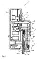
- the locking device 1 in cross section, while the locking member 4 assumes a locking position, in which it protrudes from the housing 3, in particular through the opening 8, with its working end 4b. In this locking position, the working end 4b is in an operative connection, in particular a positive connection, with the functionally essential component 2 (not in FIG FIG. 1 and 2 shown).
- the FIG. 3 is also a cross section through a steering column 17, which forms, for example, the functionally essential component 2, shown.
- the control element 5 is connected at the end to the drive element 7 via a guide pin 13.
- one end of the guide pin 13 engages in a helical guide track 7a of the drive element 7 and the other end of the guide pin 13 is slidably mounted in a guide groove 14 in the housing 3.
- the guide pin 13 is moved slowly downwards, that is, moved away parallel from the axis of rotation 12 of the drive element 7.
- the drive element 7 can be driven by an electric motor directly or indirectly via a transmission.
- a positive connection is provided between the two parts.
- This positive connection is formed for example from a cam 5a on the control element 5 and a recess 4a in the locking member 4.
- the recess 4a is made significantly larger than the cam 5a.
- the locking member 4 is pressed by the spring 10, which is arranged between the locking member 4 and the control element 5, to the cam 5a.
- additional holding means such as the projection 5c shown or holes for receiving the spring 10 may be provided.
- the locking member 4 does not protrude from the housing 3 when the functionally essential component 2 blocks the way for the locking member 4. In this case, the space shown 21, whereby damage to the locking device 1 is prevented. If the functionally essential component 2 released by a movement the way for the locking member 4, this is pressed by the spring 10 in the locking position. Thereafter, the locking member 4 is in the desired operative connection with the functionally essential component. 2
- FIG. 1 is further shown how the fuse element 6 is pressed in a wedge-like manner by the lower end provided with a shoulder of the control element 5 in a release position, so that the locking member 4 from the housing 3, in particular from the opening 8, can protrude.
- a backup of the locking member 4 is not necessary because the functionally essential component 2 is to be blocked anyway. Consequently, even a material breakage in the locking device 1 would cause no further damage or even cause an accident.
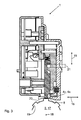
- the locking member 4 is shown in the unlocked position. As can be clearly seen, while the locking member 4 is locked positively in the region of the opening 8 by the securing element 6. In this locking position, the control element 5 does not act on the securing element 6, so that this presses the securing element 6 against the locking member 4 by means of the spring 11, which is arranged for example between the housing 3 and the securing element 6.
- the locking member 4 has even at its working end 4b a paragraph 4e to the remaining shaft of the locking member 4, with which the securing element 6 cooperates. Consequently, the securing element 6 forms in the locking position a positive connection with the locking member 4, in particular the paragraph 4e with the lower protruding part of the mirrored "L" -shaped securing element 6.
- This lower protruding part of the securing element 6 is formed deeper than the paragraph 4e to the shaft
- the upper or vertical region of the mirror-inverted "L"-shaped securing element 6 has a particular parallel distance from the shaft of the locking member 4.
- the securing element 6 is in the locking position only with its horizontally protruding part in contact with the locking member 4, whereby the desired positive connection is formed. In this case, of course, a game between the locking member 4 and the securing element 6 are present.
- the fuse element 6 is even in a guide 9 z. B. movably or displaceably mounted in the housing 3.
- the back of the spring 11 acts on the securing element 6 in order to press this against the locking member 4.
- a hole is provided in the securing element 6 to receive the spring 11 in a form-fitting manner and to position it in a stationary manner.
- a receptacle for the spring 11 may also be provided. So that the securing element 6 has the lowest possible moments of inertia, a further recess 6a, in particular in the horizontally projecting part, is provided on the rear side, whereby the weight of the securing element 6 can be reduced.
- the securing element 6 may consist of a plastic or a light metal part, which has been produced in an injection molding process.
- the control element 5 since the locking member 4 is still held in a form-fitting manner by the securing element 6 in the unlocking position, the control element 5 must first move the securing element 6 such that it occupies the release position.
- the wedge-shaped control means 5b are provided at the lower end of the control element 5 in the form of oblique or dome-shaped control surfaces. These now hit the counter-control means 6b, also in the form of oblique or dome-shaped control surfaces, on the securing element 6 during the downward movement 15 of the control element 5.
- the counter-control means 6b are arranged in the upper region of the vertical part of the securing element 6. The slopes of the respective control surfaces of the control means 5b and counter control means 6b are suitably aligned parallel to each other.
- the respective control surfaces slide on each other in the downward movement, wherein the vertical movement 15 of the control element 5 is converted into a horizontal movement 16 of the securing element 6.
- the securing element 6 is pressed against the spring 11 in the release position and repealed the positive connection between the securing element 6 and the locking member 4.
- additional guide means 6c are provided on the securing element 6 and counter guide means 4c on the locking member 4.
- These guide means 6c and counter guide means 4c are expediently also formed by oblique or dome-shaped guide surfaces, which are preferably arranged parallel to one another.
- the horizontal movement 16 of the fuse element 6 leads from the locking position in the release position to a vertical downward movement 15 of the locking member 4. If the locking member 4 with the working end 4b no protrusion or cam 19 of the functionally essential component 2, immediately finds a locking of the functionally essential Component 2 instead. Otherwise, by a rotation or movement of the functionally essential component 2 or the steering column 17 to the pivot point 18, the space for the locking member 4 released by the cam 19, so that it can engage with its working end 4b in a recess 20 between two cams 19 form-fitting manner ,
Landscapes
- Engineering & Computer Science (AREA)
- Mechanical Engineering (AREA)
- Lock And Its Accessories (AREA)
Claims (15)
- Dispositif de verrouillage (1) permettant de verrouiller et/ou de déverrouiller un élément fonctionnellement essentiel (2) d'un véhicule, avec
un boîtier (3),
un élément de blocage (4) qui, au moyen d'un élément de commande (5), peut adopter au moins deux positions, à savoir
une position de verrouillage, dans laquelle l'élément de blocage (4) dépasse hors du boîtier (3) par une ouverture (8) et est en relation active avec l'élément fonctionnellement essentiel (2),
et une position de déverrouillage, dans laquelle l'élément de blocage (4) est disposé pour l'essentiel dans le boîtier (3) et n'est pas en relation active avec l'élément fonctionnellement essentiel (2),
et un élément de sécurité (6), avec lequel l'élément de blocage (4) peut être au moins arrêté dans la position de déverrouillage,
sachant que l'élément de commande (5) présente également des moyens de commande (5b) pour actionner l'élément de sécurité (6),
caractérisé en ce
que l'élément de sécurité (6) présente des moyens de guidage (6c), qui coopèrent avec des moyens de guidage complémentaires ou de contre-guidage (4c) sur l'élément de blocage (4). - Dispositif de verrouillage (1) selon la revendication 1,
caractérisé en ce
que l'élément de commande (5) et/ou l'élément de blocage (4) sont disposés à coulissement longitudinal dans le boîtier (3). - Dispositif de verrouillage (1) selon la revendication 2,
caractérisé en ce
que l'élément de commande (5) est disposé à coulissement parallèlement à l'élément de blocage (4). - Dispositif de verrouillage (1) selon l'une des revendications 1 à 3,
caractérisé en ce
que l'élément de commande (5) est à coulissement longitudinal au moyen d'un élément d'entraînement rotatif (7). - Dispositif de verrouillage (1) selon l'une des revendications 1 à 4,
caractérisé en ce
que l'élément de commande (5) forme un engagement positif avec l'élément de blocage (4) afin de pouvoir actionner l'élément de blocage (4), sachant que l'engagement positif est formé par un ergot ou une came (5a) qui coopère avec un évidement (6a). - Dispositif de verrouillage (1) selon l'une des revendications 1 à 5,
caractérisé en ce
qu'un ressort (10) est disposé entre l'élément de commande (5) et l'élément de blocage (4) afin de produire un déplacement axial de l'élément de blocage (4) par rapport à l'élément de commande (5). - Dispositif de verrouillage (1) selon l'une des revendications 1 à 6,
caractérisé en ce
que l'élément de sécurité (6) prend, en fonction de la position de l'élément de blocage (4), au moins une position d'arrêt ou une position de libération. - Dispositif de verrouillage (1) selon l'une des revendications 1 à 7,
caractérisé en ce
que l'élément de sécurité (6) est disposé dans la région de l'ouverture (8). - Dispositif de verrouillage (1) selon l'une des revendications 1 à 8,
caractérisé en ce
que l'élément de sécurité (6) présente des moyens de commande complémentaires ou de contre-commande (6b) qui coopèrent avec les moyens de commande (5b) de l'élément de commande (5). - Dispositif de verrouillage (1) selon la revendication 9,
caractérisé en ce
que les moyens de commande (5b) et les moyens de commande complémentaires ou de contre-commande (6b) comprennent des surfaces de commande planes, en forme de calotte ou en arc, qui sont orientées en oblique par rapport à la direction de déplacement (15, 16) de l'élément de commande (5) ou respectivement de l'élément de sécurité (6). - Dispositif de verrouillage (1) selon l'une des revendications 1 à 10,
caractérisé en ce
que l'élément de sécurité (6) est monté à coulissement sur le boîtier (3). - Dispositif de verrouillage (1) selon l'une des revendications 1 à 11,
caractérisé en ce
que l'élément de sécurité (6) est sollicité par un ressort (11), de sorte qu'il peut être transféré de lui-même d'une position dans une autre. - Dispositif de verrouillage (1) selon l'une des revendications 1 à 12,
caractérisé en ce
que l'élément de commande (5) est réalisé en plusieurs parties, sachant que les parties respectives coopèrent fonctionnellement. - Dispositif de verrouillage (1) selon l'une des revendications 1 à 13,
caractérisé en ce
que l'élément de blocage (4) arrête par engagement positif l'élément fonctionnellement essentiel (2) dans la position de verrouillage, sachant que l'élément fonctionnellement essentiel (2) du véhicule est en particulier réalisé sous la forme d'une colonne de direction (17) ou d'un levier de changement de vitesse. - Véhicule, en particulier véhicule automobile, avec un dispositif de verrouillage (1) selon l'une des revendications précédentes.
Applications Claiming Priority (2)
| Application Number | Priority Date | Filing Date | Title |
|---|---|---|---|
| DE102006017875 | 2006-04-13 | ||
| PCT/EP2007/053565 WO2007118840A1 (fr) | 2006-04-13 | 2007-04-12 | Dispositif de verrouillage |
Publications (2)
| Publication Number | Publication Date |
|---|---|
| EP2010417A1 EP2010417A1 (fr) | 2009-01-07 |
| EP2010417B1 true EP2010417B1 (fr) | 2010-01-06 |
Family
ID=38222657
Family Applications (1)
| Application Number | Title | Priority Date | Filing Date |
|---|---|---|---|
| EP07728032A Not-in-force EP2010417B1 (fr) | 2006-04-13 | 2007-04-12 | Dispositif de verrouillage |
Country Status (5)
| Country | Link |
|---|---|
| EP (1) | EP2010417B1 (fr) |
| KR (1) | KR101353876B1 (fr) |
| AT (1) | ATE454295T1 (fr) |
| DE (1) | DE502007002557D1 (fr) |
| WO (1) | WO2007118840A1 (fr) |
Families Citing this family (3)
| Publication number | Priority date | Publication date | Assignee | Title |
|---|---|---|---|---|
| DE102007059713A1 (de) * | 2007-12-10 | 2009-06-18 | Huf Hülsbeck & Fürst Gmbh & Co. Kg | Vorrichtung zur Ansteuerung eines Sperrgliedes |
| ATE553010T1 (de) * | 2007-12-31 | 2012-04-15 | Valeo Sicherheitssysteme Gmbh | Motorisierte lenkverriegelungsvorrichtung |
| DE102019125189A1 (de) * | 2019-09-19 | 2021-03-25 | Huf Hülsbeck & Fürst Gmbh & Co. Kg | Verriegelungsvorrichtung für ein funktionswesentliches Bauteil, Funktionseinheit für ein Fahrzeug sowie Verfahren zum zerstörungsfreien Abstützen einer Bewegung eines funktionswesentlichen Bauteils |
Family Cites Families (3)
| Publication number | Priority date | Publication date | Assignee | Title |
|---|---|---|---|---|
| IT1155605B (it) * | 1982-02-12 | 1987-01-28 | Champion Spark Plug Italiana | Antifurto bloccasterzo per autoveicoli |
| JPS5914562A (ja) * | 1982-07-15 | 1984-01-25 | Kokusan Kinzoku Kogyo Co Ltd | キ−レスステアリングロツク装置 |
| IT1320542B1 (it) * | 2000-07-18 | 2003-12-10 | Trw Italia Spa | Bloccasterzo elettrico per veicoli. |
-
2007
- 2007-04-12 AT AT07728032T patent/ATE454295T1/de active
- 2007-04-12 KR KR1020087027115A patent/KR101353876B1/ko active IP Right Grant
- 2007-04-12 WO PCT/EP2007/053565 patent/WO2007118840A1/fr active Application Filing
- 2007-04-12 EP EP07728032A patent/EP2010417B1/fr not_active Not-in-force
- 2007-04-12 DE DE502007002557T patent/DE502007002557D1/de active Active
Also Published As
| Publication number | Publication date |
|---|---|
| EP2010417A1 (fr) | 2009-01-07 |
| WO2007118840A1 (fr) | 2007-10-25 |
| KR101353876B1 (ko) | 2014-01-20 |
| KR20090005154A (ko) | 2009-01-12 |
| DE502007002557D1 (de) | 2010-02-25 |
| ATE454295T1 (de) | 2010-01-15 |
Similar Documents
| Publication | Publication Date | Title |
|---|---|---|
| EP2504219B2 (fr) | Colonne de direction pour un véhicule à moteur | |
| EP2569498A1 (fr) | Dispositif à poignée, en particulier pour un véhicule | |
| EP1539391B1 (fr) | Outil de cintrage et dispositif porte-outil associe | |
| DE102007059710B4 (de) | Kompakte Verriegelungsvorrichtung mit Sicherungselement | |
| WO2014027099A1 (fr) | Unité poignée de porte à fonction de sécurité | |
| EP2010417B1 (fr) | Dispositif de verrouillage | |
| EP1982878B1 (fr) | Dispositif de commande d'un organe de verrouillage | |
| WO2006000537A1 (fr) | Dispositif de verrouillage et / ou de deverrouillage du volant d'un vehicule a moteur | |
| DE10335311A1 (de) | Lenkschlossvorrichtung | |
| DE102005050920B4 (de) | Verriegelungsvorrichtung | |
| EP3243980A1 (fr) | Système de verrouillage | |
| WO2009030704A1 (fr) | Dispositif de commande d'un élément de blocage | |
| EP1249375B1 (fr) | Dispositif de verrouillage pour la colonne de direction d'un véhicule | |
| DE4407912C2 (de) | Elektromechanisches Schloß | |
| DE102021109993B3 (de) | Sicherheitsschalter mit Zuhaltung | |
| EP0782510B1 (fr) | Commutateur monte sur la colonne de direction, servant d'organe de changement de vitesses avec possibilite de fixation en position neutre | |
| WO2022069177A1 (fr) | Dispositif de verrouillage et procédé de verrouillage pour entraînement d'aiguillage et entraînement d'aiguillage | |
| DE19809346B4 (de) | Elektromechanische Schließvorrichtung, insbesondere Schloß | |
| DE19526660B4 (de) | Elektromechanisches Schloß | |
| DE2355922C3 (de) | Kraftfahrzeug-Lenkschloß | |
| EP2099659B1 (fr) | Dispositif de commande d'un élément de verrouillage | |
| EP2993287B1 (fr) | Barre enfonçable pour l'actionnement d'une fermeture de porte | |
| EP0990758A2 (fr) | Serrure additionelle pour crémone | |
| DE4331091C1 (de) | Handbetätigter Schalter mit einer Verriegelung | |
| DE102016004835B4 (de) | Sicherheitsschalter |
Legal Events
| Date | Code | Title | Description |
|---|---|---|---|
| PUAI | Public reference made under article 153(3) epc to a published international application that has entered the european phase |
Free format text: ORIGINAL CODE: 0009012 |
|
| 17P | Request for examination filed |
Effective date: 20081113 |
|
| AK | Designated contracting states |
Kind code of ref document: A1 Designated state(s): AT BE BG CH CY CZ DE DK EE ES FI FR GB GR HU IE IS IT LI LT LU LV MC MT NL PL PT RO SE SI SK TR |
|
| AX | Request for extension of the european patent |
Extension state: AL BA HR MK RS |
|
| 17Q | First examination report despatched |
Effective date: 20090220 |
|
| GRAP | Despatch of communication of intention to grant a patent |
Free format text: ORIGINAL CODE: EPIDOSNIGR1 |
|
| DAX | Request for extension of the european patent (deleted) | ||
| GRAS | Grant fee paid |
Free format text: ORIGINAL CODE: EPIDOSNIGR3 |
|
| GRAA | (expected) grant |
Free format text: ORIGINAL CODE: 0009210 |
|
| AK | Designated contracting states |
Kind code of ref document: B1 Designated state(s): AT BE BG CH CY CZ DE DK EE ES FI FR GB GR HU IE IS IT LI LT LU LV MC MT NL PL PT RO SE SI SK TR |
|
| REG | Reference to a national code |
Ref country code: GB Ref legal event code: FG4D Free format text: NOT ENGLISH |
|
| REG | Reference to a national code |
Ref country code: CH Ref legal event code: EP |
|
| REG | Reference to a national code |
Ref country code: IE Ref legal event code: FG4D |
|
| REF | Corresponds to: |
Ref document number: 502007002557 Country of ref document: DE Date of ref document: 20100225 Kind code of ref document: P |
|
| REG | Reference to a national code |
Ref country code: NL Ref legal event code: VDEP Effective date: 20100106 |
|
| PG25 | Lapsed in a contracting state [announced via postgrant information from national office to epo] |
Ref country code: SI Free format text: LAPSE BECAUSE OF FAILURE TO SUBMIT A TRANSLATION OF THE DESCRIPTION OR TO PAY THE FEE WITHIN THE PRESCRIBED TIME-LIMIT Effective date: 20100106 |
|
| LTIE | Lt: invalidation of european patent or patent extension |
Effective date: 20100106 |
|
| PG25 | Lapsed in a contracting state [announced via postgrant information from national office to epo] |
Ref country code: PT Free format text: LAPSE BECAUSE OF FAILURE TO SUBMIT A TRANSLATION OF THE DESCRIPTION OR TO PAY THE FEE WITHIN THE PRESCRIBED TIME-LIMIT Effective date: 20100506 Ref country code: ES Free format text: LAPSE BECAUSE OF FAILURE TO SUBMIT A TRANSLATION OF THE DESCRIPTION OR TO PAY THE FEE WITHIN THE PRESCRIBED TIME-LIMIT Effective date: 20100417 Ref country code: NL Free format text: LAPSE BECAUSE OF FAILURE TO SUBMIT A TRANSLATION OF THE DESCRIPTION OR TO PAY THE FEE WITHIN THE PRESCRIBED TIME-LIMIT Effective date: 20100106 Ref country code: IS Free format text: LAPSE BECAUSE OF FAILURE TO SUBMIT A TRANSLATION OF THE DESCRIPTION OR TO PAY THE FEE WITHIN THE PRESCRIBED TIME-LIMIT Effective date: 20100506 Ref country code: LT Free format text: LAPSE BECAUSE OF FAILURE TO SUBMIT A TRANSLATION OF THE DESCRIPTION OR TO PAY THE FEE WITHIN THE PRESCRIBED TIME-LIMIT Effective date: 20100106 |
|
| REG | Reference to a national code |
Ref country code: IE Ref legal event code: FD4D |
|
| PG25 | Lapsed in a contracting state [announced via postgrant information from national office to epo] |
Ref country code: FI Free format text: LAPSE BECAUSE OF FAILURE TO SUBMIT A TRANSLATION OF THE DESCRIPTION OR TO PAY THE FEE WITHIN THE PRESCRIBED TIME-LIMIT Effective date: 20100106 Ref country code: LV Free format text: LAPSE BECAUSE OF FAILURE TO SUBMIT A TRANSLATION OF THE DESCRIPTION OR TO PAY THE FEE WITHIN THE PRESCRIBED TIME-LIMIT Effective date: 20100106 Ref country code: PL Free format text: LAPSE BECAUSE OF FAILURE TO SUBMIT A TRANSLATION OF THE DESCRIPTION OR TO PAY THE FEE WITHIN THE PRESCRIBED TIME-LIMIT Effective date: 20100106 |
|
| PG25 | Lapsed in a contracting state [announced via postgrant information from national office to epo] |
Ref country code: GR Free format text: LAPSE BECAUSE OF FAILURE TO SUBMIT A TRANSLATION OF THE DESCRIPTION OR TO PAY THE FEE WITHIN THE PRESCRIBED TIME-LIMIT Effective date: 20100407 Ref country code: EE Free format text: LAPSE BECAUSE OF FAILURE TO SUBMIT A TRANSLATION OF THE DESCRIPTION OR TO PAY THE FEE WITHIN THE PRESCRIBED TIME-LIMIT Effective date: 20100106 Ref country code: CY Free format text: LAPSE BECAUSE OF FAILURE TO SUBMIT A TRANSLATION OF THE DESCRIPTION OR TO PAY THE FEE WITHIN THE PRESCRIBED TIME-LIMIT Effective date: 20100106 Ref country code: IE Free format text: LAPSE BECAUSE OF FAILURE TO SUBMIT A TRANSLATION OF THE DESCRIPTION OR TO PAY THE FEE WITHIN THE PRESCRIBED TIME-LIMIT Effective date: 20100106 Ref country code: SE Free format text: LAPSE BECAUSE OF FAILURE TO SUBMIT A TRANSLATION OF THE DESCRIPTION OR TO PAY THE FEE WITHIN THE PRESCRIBED TIME-LIMIT Effective date: 20100106 Ref country code: RO Free format text: LAPSE BECAUSE OF FAILURE TO SUBMIT A TRANSLATION OF THE DESCRIPTION OR TO PAY THE FEE WITHIN THE PRESCRIBED TIME-LIMIT Effective date: 20100106 |
|
| BERE | Be: lapsed |
Owner name: HUF HULSBECK & FURST G.M.B.H. & CO. KG Effective date: 20100430 |
|
| PLBE | No opposition filed within time limit |
Free format text: ORIGINAL CODE: 0009261 |
|
| STAA | Information on the status of an ep patent application or granted ep patent |
Free format text: STATUS: NO OPPOSITION FILED WITHIN TIME LIMIT |
|
| PG25 | Lapsed in a contracting state [announced via postgrant information from national office to epo] |
Ref country code: CZ Free format text: LAPSE BECAUSE OF FAILURE TO SUBMIT A TRANSLATION OF THE DESCRIPTION OR TO PAY THE FEE WITHIN THE PRESCRIBED TIME-LIMIT Effective date: 20100106 Ref country code: MC Free format text: LAPSE BECAUSE OF NON-PAYMENT OF DUE FEES Effective date: 20100430 Ref country code: BG Free format text: LAPSE BECAUSE OF FAILURE TO SUBMIT A TRANSLATION OF THE DESCRIPTION OR TO PAY THE FEE WITHIN THE PRESCRIBED TIME-LIMIT Effective date: 20100406 Ref country code: SK Free format text: LAPSE BECAUSE OF FAILURE TO SUBMIT A TRANSLATION OF THE DESCRIPTION OR TO PAY THE FEE WITHIN THE PRESCRIBED TIME-LIMIT Effective date: 20100106 |
|
| 26N | No opposition filed |
Effective date: 20101007 |
|
| REG | Reference to a national code |
Ref country code: FR Ref legal event code: ST Effective date: 20101230 |
|
| PG25 | Lapsed in a contracting state [announced via postgrant information from national office to epo] |
Ref country code: DK Free format text: LAPSE BECAUSE OF FAILURE TO SUBMIT A TRANSLATION OF THE DESCRIPTION OR TO PAY THE FEE WITHIN THE PRESCRIBED TIME-LIMIT Effective date: 20100106 |
|
| PG25 | Lapsed in a contracting state [announced via postgrant information from national office to epo] |
Ref country code: IT Free format text: LAPSE BECAUSE OF FAILURE TO SUBMIT A TRANSLATION OF THE DESCRIPTION OR TO PAY THE FEE WITHIN THE PRESCRIBED TIME-LIMIT Effective date: 20100106 Ref country code: BE Free format text: LAPSE BECAUSE OF NON-PAYMENT OF DUE FEES Effective date: 20100430 |
|
| PG25 | Lapsed in a contracting state [announced via postgrant information from national office to epo] |
Ref country code: MT Free format text: LAPSE BECAUSE OF FAILURE TO SUBMIT A TRANSLATION OF THE DESCRIPTION OR TO PAY THE FEE WITHIN THE PRESCRIBED TIME-LIMIT Effective date: 20100106 |
|
| REG | Reference to a national code |
Ref country code: CH Ref legal event code: PL |
|
| GBPC | Gb: european patent ceased through non-payment of renewal fee |
Effective date: 20110412 |
|
| PG25 | Lapsed in a contracting state [announced via postgrant information from national office to epo] |
Ref country code: LI Free format text: LAPSE BECAUSE OF NON-PAYMENT OF DUE FEES Effective date: 20110430 Ref country code: CH Free format text: LAPSE BECAUSE OF NON-PAYMENT OF DUE FEES Effective date: 20110430 |
|
| PG25 | Lapsed in a contracting state [announced via postgrant information from national office to epo] |
Ref country code: GB Free format text: LAPSE BECAUSE OF NON-PAYMENT OF DUE FEES Effective date: 20110412 |
|
| PG25 | Lapsed in a contracting state [announced via postgrant information from national office to epo] |
Ref country code: FR Free format text: LAPSE BECAUSE OF NON-PAYMENT OF DUE FEES Effective date: 20100430 |
|
| PG25 | Lapsed in a contracting state [announced via postgrant information from national office to epo] |
Ref country code: LU Free format text: LAPSE BECAUSE OF NON-PAYMENT OF DUE FEES Effective date: 20100412 Ref country code: HU Free format text: LAPSE BECAUSE OF FAILURE TO SUBMIT A TRANSLATION OF THE DESCRIPTION OR TO PAY THE FEE WITHIN THE PRESCRIBED TIME-LIMIT Effective date: 20100707 |
|
| PG25 | Lapsed in a contracting state [announced via postgrant information from national office to epo] |
Ref country code: TR Free format text: LAPSE BECAUSE OF FAILURE TO SUBMIT A TRANSLATION OF THE DESCRIPTION OR TO PAY THE FEE WITHIN THE PRESCRIBED TIME-LIMIT Effective date: 20100106 |
|
| REG | Reference to a national code |
Ref country code: AT Ref legal event code: MM01 Ref document number: 454295 Country of ref document: AT Kind code of ref document: T Effective date: 20120412 |
|
| PG25 | Lapsed in a contracting state [announced via postgrant information from national office to epo] |
Ref country code: AT Free format text: LAPSE BECAUSE OF NON-PAYMENT OF DUE FEES Effective date: 20120412 |
|
| PGFP | Annual fee paid to national office [announced via postgrant information from national office to epo] |
Ref country code: DE Payment date: 20200430 Year of fee payment: 14 |
|
| REG | Reference to a national code |
Ref country code: DE Ref legal event code: R119 Ref document number: 502007002557 Country of ref document: DE |
|
| PG25 | Lapsed in a contracting state [announced via postgrant information from national office to epo] |
Ref country code: DE Free format text: LAPSE BECAUSE OF NON-PAYMENT OF DUE FEES Effective date: 20211103 |