EP2010417B1 - Locking device - Google Patents
Locking device Download PDFInfo
- Publication number
- EP2010417B1 EP2010417B1 EP07728032A EP07728032A EP2010417B1 EP 2010417 B1 EP2010417 B1 EP 2010417B1 EP 07728032 A EP07728032 A EP 07728032A EP 07728032 A EP07728032 A EP 07728032A EP 2010417 B1 EP2010417 B1 EP 2010417B1
- Authority
- EP
- European Patent Office
- Prior art keywords
- locking device
- locking
- blocking element
- control
- locking member
- Prior art date
- Legal status (The legal status is an assumption and is not a legal conclusion. Google has not performed a legal analysis and makes no representation as to the accuracy of the status listed.)
- Not-in-force
Links
Images

Classifications
-
- B—PERFORMING OPERATIONS; TRANSPORTING
- B60—VEHICLES IN GENERAL
- B60R—VEHICLES, VEHICLE FITTINGS, OR VEHICLE PARTS, NOT OTHERWISE PROVIDED FOR
- B60R25/00—Fittings or systems for preventing or indicating unauthorised use or theft of vehicles
- B60R25/01—Fittings or systems for preventing or indicating unauthorised use or theft of vehicles operating on vehicle systems or fittings, e.g. on doors, seats or windscreens
- B60R25/02—Fittings or systems for preventing or indicating unauthorised use or theft of vehicles operating on vehicle systems or fittings, e.g. on doors, seats or windscreens operating on the steering mechanism
- B60R25/021—Fittings or systems for preventing or indicating unauthorised use or theft of vehicles operating on vehicle systems or fittings, e.g. on doors, seats or windscreens operating on the steering mechanism restraining movement of the steering column or steering wheel hub, e.g. restraining means controlled by ignition switch
- B60R25/0215—Fittings or systems for preventing or indicating unauthorised use or theft of vehicles operating on vehicle systems or fittings, e.g. on doors, seats or windscreens operating on the steering mechanism restraining movement of the steering column or steering wheel hub, e.g. restraining means controlled by ignition switch using electric means, e.g. electric motors or solenoids
- B60R25/02153—Fittings or systems for preventing or indicating unauthorised use or theft of vehicles operating on vehicle systems or fittings, e.g. on doors, seats or windscreens operating on the steering mechanism restraining movement of the steering column or steering wheel hub, e.g. restraining means controlled by ignition switch using electric means, e.g. electric motors or solenoids comprising a locking member radially and linearly moved towards the steering column
-
- B—PERFORMING OPERATIONS; TRANSPORTING
- B60—VEHICLES IN GENERAL
- B60R—VEHICLES, VEHICLE FITTINGS, OR VEHICLE PARTS, NOT OTHERWISE PROVIDED FOR
- B60R25/00—Fittings or systems for preventing or indicating unauthorised use or theft of vehicles
- B60R25/01—Fittings or systems for preventing or indicating unauthorised use or theft of vehicles operating on vehicle systems or fittings, e.g. on doors, seats or windscreens
- B60R25/02—Fittings or systems for preventing or indicating unauthorised use or theft of vehicles operating on vehicle systems or fittings, e.g. on doors, seats or windscreens operating on the steering mechanism
- B60R25/023—Countermeasures against the physical destruction of the steering lock
Definitions
- the present invention is directed to a locking device according to the preamble of claim 1 for locking and / or unlocking a functionally essential component in a vehicle, such as a steering column or a gearshift lever od.
- a locking member is used, which protrudes in a locking position from the housing of the locking device and is in an operative connection, in particular by a positive connection, with the functionally essential component and thereby blocks it.
- an application intended use of the functionally essential component in the locking position is not possible.
- an application intended use in the unlocked position of the locking member is possible, wherein the locking member is then not in operative connection with the functionally essential component.
- the blocking element has on its axial circumference a groove into which engages the safety lever.
- a weakening of the blocking element takes place, which can lead to fatigue fracture of the blocking element in the long term. Consequently, it can not be ruled out that the blocking element nevertheless leads to a locking of the steering spindle in the event of a break.
- the forces acting in an accident forces may favor a premature breakage of the blocking element.
- the generic document EP 1 174 314 A2 also discloses a locking member which is locked by a securing element in the unlocked position. If the lock is released, then the locking member moves by the force of a spring and thus jerkily in the locking position. The securing element locks the locking member away from the housing opening so that when the locking member breaks, the steering column can be inadvertently blocked.
- the publication GB 2 114 646 A discloses a locking member which is secured via a locking lever in the unlocked position. Here, the safety lever is moved over a complicated mechanism. Also the JP 59014562 discloses a generic steering lock, in which, however, not the locking member itself, but a control is secured by a securing element.
- the locking device according to the invention is usually arranged in a so-called 12 o'clock position in the vehicle - but it is not limited to this installation position - to complicate a possible theft or attempted break-up or even to avoid. In this 12 o'clock position, the locking device is arranged in an inaccessible position in the vehicle. However, the locking member must be secured against accidental dropping in such an arrangement of the locking device.
- the existing control element has at least one additional control means for actuating the securing element, whereby likewise an actuation of the securing element by the control is possible. Consequently, in the present invention, the control used is used not only for the actuation of the locking member but simultaneously for the actuation of the securing element. This is a particularly simple and inexpensive construction of the invention Locking device with few components possible. Also can be dispensed with in the present locking device to an additional drive for the actuation of the fuse element. In addition, it can thus be ensured that no mechanical fragments from the locking device lead to an undesired locking of the functionally essential component.
- control element and / or the blocking element can be arranged to be longitudinally displaceable in the housing of the device. Due to the simple linear movement of the control element or the locking member, a space-saving design of the locking device can be realized.
- control parallel to the locking member slidably.
- the actual longitudinal displacement of the control element can be generated via a rotatable drive element.
- This drive element may itself consist of a motor or a driven disc with a flat guideway. By this spiral-shaped guideway, it is possible not to design the longitudinal displacement of the control element in proportion to the rotation of the drive element. This makes it possible to effect different process speeds for the control and thus the locking member in the individual movement sections.
- the control to the locking member on a positive engagement whereby the actuation of the locking member is effected.
- This positive connection can be formed from a cam which cooperates with a recess.
- the cam is arranged on the control element and protrudes into the recess which is arranged in the blocking member.
- the control is not rigidly disposed to the locking member, it is expedient to design the recess larger than the dimensions of the cam, so as to use the existing space for a game between the control and the locking member. Because of this Game can be achieved, that the locking member is not forcibly guided by the control, whereby damage to the locking device can be avoided.
- the locking member can not protrude from the housing, if there obstructs the functionally essential component with a cam the required space. Only when there is a shift or rotation of the functionally essential component, whereby the retaining cam releases the space for the locking member, this can then enter into the desired operative connection with the functionally essential component.
- a spring is arranged between the control element and the blocking element in order to bring about the desired axial displacement of the blocking element relative to the control element.
- the control presses the locking member out of the housing of the locking device, which can only enter into operative connection with the functionally essential component, if it does not stand in the way of the locking member directly.
- the locking member is guided by the spring action in a recess or behind a cam of the functionally essential component.
- the securing element used has at least one locking position or a release position depending on the position of the locking member.
- the locking member In the unlocked position of the locking member in which there is no operative connection with the functionally essential component, the locking member is positively secured by the securing element, which is located in the locking position.
- the positive connection between the fuse element and the locking member In the release position of the fuse element, however, the positive connection between the fuse element and the locking member is released, so that the locking member can move into the locking position or has already taken this.
- the positive connection between the securing element and the locking member may consist of a shoulder on the locking member, behind which the securing element moves in the locking position.
- the securing element with a spring be acted upon, whereby it can be independently transferred from the release position into the locking position.
- the spring provided for this purpose can be arranged so that always a slight pressure is exerted by the securing element on the locking member in the locking position. This ensures that in the unlocked position of the locking member no fractions can escape from the opening of the housing and cause an unintentional blockage of the functionally essential component. Even the break of the locking member would not lead to a blockage of the functionally essential component, since the locking member is positively and non-positively held by the spring-loaded securing element in the locking position.
- the securing element is arranged in the region of the housing opening for the locking member. This ensures that in case of a defect of the locking device from the housing opening no components or fragments can escape.
- the securing element In order to actuate the securing element in a simple manner by the control or the corresponding control means, the securing element has counter-control means which cooperate with the control means of the control element. In this case, a longitudinal displacement of the control element also leads to an actuation of the securing element, since the control means cooperates on the control element with the counter-control means of the securing element such that the securing element is actuated. In this operation, the control wedge moves the fuse element from the locking position to the release position or vice versa.
- the control means and counter control means each have a planar, dome-shaped or arc-shaped control surface, which is oriented substantially obliquely to the respective direction of movement of the control element or the securing element.
- the control means slides from Control on the counter-control means of the fuse element along.
- the securing element is displaceably mounted in the housing of the locking device.
- longitudinal guides can be provided on the housing. These guides may consist of one or more grooves in which the fuse element is guided. It is also conceivable that a protruding from the housing pin cooperates with a corresponding recess in the fuse element to take over the leadership of the fuse element.
- the securing element has guide means which cooperate with counter-guide means on the locking member.
- the guide means and counter guide means can be configured as inclined surfaces sliding on each other. These surfaces can also be designed dome-shaped or curved. Consequently, the locking member slides with its guide means when moving out of the housing on the counter guide means of the securing element.
- control is constructed in several parts.
- the respective components may contain the same or a different material.
- z. B. the component which is required for driving the locking member, have a light metal alloy, and the component which contains the control means, made of plastic.
- all components of the control element consist of the same material.
- the respective components of the control functionally cooperate with the type, so that the previously described functions of the control are present in any case, but possibly even more can be added.
- the locking member locks the functionally essential component in the locking position in a form-fitting manner.
- the functionally essential component of the vehicle can be designed as a steering column or a gearshift lever or the like. In the locking position, the steering column or the gear shift lever is locked by the locking member form-fitting manner.
- the invention is also directed to a vehicle, in particular motor vehicle with a locking device according to one of claims 1 to 15.
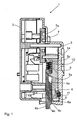
- the locking device 1 in cross section, while the locking member 4 assumes a locking position, in which it protrudes from the housing 3, in particular through the opening 8, with its working end 4b. In this locking position, the working end 4b is in an operative connection, in particular a positive connection, with the functionally essential component 2 (not in FIG FIG. 1 and 2 shown).
- the FIG. 3 is also a cross section through a steering column 17, which forms, for example, the functionally essential component 2, shown.
- the control element 5 is connected at the end to the drive element 7 via a guide pin 13.
- one end of the guide pin 13 engages in a helical guide track 7a of the drive element 7 and the other end of the guide pin 13 is slidably mounted in a guide groove 14 in the housing 3.
- the guide pin 13 is moved slowly downwards, that is, moved away parallel from the axis of rotation 12 of the drive element 7.
- the drive element 7 can be driven by an electric motor directly or indirectly via a transmission.
- a positive connection is provided between the two parts.
- This positive connection is formed for example from a cam 5a on the control element 5 and a recess 4a in the locking member 4.
- the recess 4a is made significantly larger than the cam 5a.
- the locking member 4 is pressed by the spring 10, which is arranged between the locking member 4 and the control element 5, to the cam 5a.
- additional holding means such as the projection 5c shown or holes for receiving the spring 10 may be provided.
- the locking member 4 does not protrude from the housing 3 when the functionally essential component 2 blocks the way for the locking member 4. In this case, the space shown 21, whereby damage to the locking device 1 is prevented. If the functionally essential component 2 released by a movement the way for the locking member 4, this is pressed by the spring 10 in the locking position. Thereafter, the locking member 4 is in the desired operative connection with the functionally essential component. 2
- FIG. 1 is further shown how the fuse element 6 is pressed in a wedge-like manner by the lower end provided with a shoulder of the control element 5 in a release position, so that the locking member 4 from the housing 3, in particular from the opening 8, can protrude.
- a backup of the locking member 4 is not necessary because the functionally essential component 2 is to be blocked anyway. Consequently, even a material breakage in the locking device 1 would cause no further damage or even cause an accident.
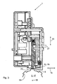
- the locking member 4 is shown in the unlocked position. As can be clearly seen, while the locking member 4 is locked positively in the region of the opening 8 by the securing element 6. In this locking position, the control element 5 does not act on the securing element 6, so that this presses the securing element 6 against the locking member 4 by means of the spring 11, which is arranged for example between the housing 3 and the securing element 6.
- the locking member 4 has even at its working end 4b a paragraph 4e to the remaining shaft of the locking member 4, with which the securing element 6 cooperates. Consequently, the securing element 6 forms in the locking position a positive connection with the locking member 4, in particular the paragraph 4e with the lower protruding part of the mirrored "L" -shaped securing element 6.
- This lower protruding part of the securing element 6 is formed deeper than the paragraph 4e to the shaft
- the upper or vertical region of the mirror-inverted "L"-shaped securing element 6 has a particular parallel distance from the shaft of the locking member 4.
- the securing element 6 is in the locking position only with its horizontally protruding part in contact with the locking member 4, whereby the desired positive connection is formed. In this case, of course, a game between the locking member 4 and the securing element 6 are present.
- the fuse element 6 is even in a guide 9 z. B. movably or displaceably mounted in the housing 3.
- the back of the spring 11 acts on the securing element 6 in order to press this against the locking member 4.
- a hole is provided in the securing element 6 to receive the spring 11 in a form-fitting manner and to position it in a stationary manner.
- a receptacle for the spring 11 may also be provided. So that the securing element 6 has the lowest possible moments of inertia, a further recess 6a, in particular in the horizontally projecting part, is provided on the rear side, whereby the weight of the securing element 6 can be reduced.
- the securing element 6 may consist of a plastic or a light metal part, which has been produced in an injection molding process.
- the control element 5 since the locking member 4 is still held in a form-fitting manner by the securing element 6 in the unlocking position, the control element 5 must first move the securing element 6 such that it occupies the release position.
- the wedge-shaped control means 5b are provided at the lower end of the control element 5 in the form of oblique or dome-shaped control surfaces. These now hit the counter-control means 6b, also in the form of oblique or dome-shaped control surfaces, on the securing element 6 during the downward movement 15 of the control element 5.
- the counter-control means 6b are arranged in the upper region of the vertical part of the securing element 6. The slopes of the respective control surfaces of the control means 5b and counter control means 6b are suitably aligned parallel to each other.
- the respective control surfaces slide on each other in the downward movement, wherein the vertical movement 15 of the control element 5 is converted into a horizontal movement 16 of the securing element 6.
- the securing element 6 is pressed against the spring 11 in the release position and repealed the positive connection between the securing element 6 and the locking member 4.
- additional guide means 6c are provided on the securing element 6 and counter guide means 4c on the locking member 4.
- These guide means 6c and counter guide means 4c are expediently also formed by oblique or dome-shaped guide surfaces, which are preferably arranged parallel to one another.
- the horizontal movement 16 of the fuse element 6 leads from the locking position in the release position to a vertical downward movement 15 of the locking member 4. If the locking member 4 with the working end 4b no protrusion or cam 19 of the functionally essential component 2, immediately finds a locking of the functionally essential Component 2 instead. Otherwise, by a rotation or movement of the functionally essential component 2 or the steering column 17 to the pivot point 18, the space for the locking member 4 released by the cam 19, so that it can engage with its working end 4b in a recess 20 between two cams 19 form-fitting manner ,
Abstract
Description
Die vorliegende Erfindung ist auf eine Verriegelungsvorrichtung gemäß dem Oberbegriff des Anspruches 1 zum Verriegeln und/oder Entriegeln eines funktionswesentlichen Bauteils bei einem Fahrzeug, wie zum Beispiel einer Lenksäule oder eines Gangschalthebels od. dgl., gerichtet. Dabei kommt ein Sperrglied zum Einsatz, welches in einer Verriegelungsposition aus dem Gehäuse der Verriegelungsvorrichtung herausragt und in einer Wirkverbindung, insbesondere durch einen Formschluss, mit dem funktionswesentlichen Bauteil steht und es dadurch blockiert. Somit ist eine anwendungsvorgesehene Benutzung des funktionswesentlichen Bauteils in der Verriegelungsposition nicht möglich. Dagegen wird eine anwendungsvorgesehene Benutzung in der Entriegelungsposition des Sperrgliedes möglich, wobei das Sperrglied dann nicht in einer Wirkverbindung mit dem funktionswesentlichen Bauteil steht.The present invention is directed to a locking device according to the preamble of
Aus dem Stand der Technik ist die Druckschrift
Aus der Offenlegungsschrift
Um die zuvor genannten Verriegelungsvorrichtungen auch gegen Fehlbetätigung des elektrischen Antriebes zu sichern, ist beispielsweise aus der Patentschrift
Besonders die bei einem Unfall wirkenden Kräfte können einen vorzeitigen Bruch des Sperrelementes begünstigen.In particular, the forces acting in an accident forces may favor a premature breakage of the blocking element.
Die gattungsbildende Druckschrift
Die Druckschrift
Ausgehend von dem zuvor erwähnten Stand der Technik ist es Aufgabe der vorliegenden Erfindung, eine rein mechanische oder elektromechanische Verriegelungsvorrichtung zu schaffen, die über einen einfachen und sicheren Aufbau verfügt, und bei welcher das Sicherungselement in einer Arretierungsstellung einen Formschluss mit dem Sperrglied eingeht. Durch die besondere Arretierung des Sperrgliedes mittels des Sicherungselements soll weiterhin erreicht werden, dass keine Bruchstücke aus der Verriegelungsvorrichtung zu einer Blockade des funktionswesentlichen Bauteils während der Fahrt führen können.Based on the aforementioned prior art, it is an object of the present invention to provide a purely mechanical or electromechanical locking device, which has a simple and safe construction, and in which the securing element enters into a locking position a positive connection with the locking member. Due to the special locking of the locking member by means of the securing element is to be further achieved that no fragments of the locking device can lead to a blockage of the functionally essential component while driving.
Die Aufgabe wird bei einer gattungsgemäßen Verriegelungsvorrichtung durch die kennzeichnenden Merkmale des Anspruches 1 gelöst, denen folgende besondere Bedeutung zukommt.The object is achieved in a generic locking device by the characterizing features of
Die erfindungsgemäße Verriegelungsvorrichtung wird in der Regel in einer sogenannten 12 Uhr-Stellung im Fahrzeug angeordnet - wobei sie jedoch nicht auf diese Einbaustellung beschränkt ist -, um einen möglichen Diebstahl oder Aufbruchsversuch zu erschweren oder sogar zu vermeiden. In dieser 12 Uhr-Stellung ist die Verriegelungsvorrichtung in einer unzugängliche Stellung im Fahrzeug angeordnet. Allerdings muss das Sperrglied bei einer solchen Anordnung der Verriegelungsvorrichtung gegen unbeabsichtigtes Herunterfallen gesichert werden.The locking device according to the invention is usually arranged in a so-called 12 o'clock position in the vehicle - but it is not limited to this installation position - to complicate a possible theft or attempted break-up or even to avoid. In this 12 o'clock position, the locking device is arranged in an inaccessible position in the vehicle. However, the locking member must be secured against accidental dropping in such an arrangement of the locking device.
Ansonsten kann es zu einer ungewollten Verriegelung des funktionswesentlichen Bauteils kommen. Erfindungsgemäß ist es vorgesehen, dass bei einer rein mechanischen oder elektromechanischen Verriegelungsvorrichtung das vorhandene Steuerelement über zumindest ein zusätzliches Steuermittel zur Betätigung des Sicherungselementes verfügt, wodurch ebenfalls eine Betätigung des Sicherungselementes durch das Steuerelement möglich ist. Folglich wird bei der vorliegenden Erfindung das eingesetzte Steuerelement nicht nur für die Betätigung des Sperrgliedes sondern gleichzeitig für die Betätigung des Sicherungselementes genutzt. Damit ist ein besonders einfacher und kostengünstiger Aufbau der erfindungsgemäßen Verriegelungsvorrichtung mit wenigen Bauteilen möglich. Ebenfalls kann bei der vorliegenden Verriegelungsvorrichtung auf einen zusätzlichen Antrieb für die Betätigung des Sicherungselementes verzichtet werden. Außerdem kann somit sichergestellt werden, dass keine mechanischen Bruchstücke aus der Verriegelungsvorrichtung zu einer ungewünschten Verriegelung des funktionswesentlichen Bauteils führen.Otherwise, there may be an unwanted locking of the functionally essential component. According to the invention, it is provided that in a purely mechanical or electromechanical locking device, the existing control element has at least one additional control means for actuating the securing element, whereby likewise an actuation of the securing element by the control is possible. Consequently, in the present invention, the control used is used not only for the actuation of the locking member but simultaneously for the actuation of the securing element. This is a particularly simple and inexpensive construction of the invention Locking device with few components possible. Also can be dispensed with in the present locking device to an additional drive for the actuation of the fuse element. In addition, it can thus be ensured that no mechanical fragments from the locking device lead to an undesired locking of the functionally essential component.
Weitere Ausführungsformen der erfindungsgemäßen Verriegelungsvorrichtung sind in den Unteransprüchen 2 bis 15 beschrieben.Further embodiments of the locking device according to the invention are described in the subclaims 2 to 15.
Bei der erfindungsgemäßen Verriegelungsvorrichtung können das Steuerelement und/oder das Sperrglied längsverschiebbar im Gehäuse der Vorrichtung angeordnet sein. Durch die einfache Linearbewegung des Steuerelementes bzw. des Sperrgliedes kann ein platzsparender Aufbau der Verriegelungsvorrichtung realisiert werden. Außerdem ist es möglich, das Steuerelement parallel zum Sperrglied verschiebbar anzuordnen. Dabei kann die eigentliche Längsverschiebung des Steuerelementes über ein drehbares Antriebselement erzeugt werden. Dieses Antriebselement kann selbst aus einem Motor oder einer angetriebenen Scheibe mit einer ebenen Führungsbahn bestehen. Durch diese spiralförmige Führungsbahn ist es möglich, die Längsverschiebung des Steuerelementes nicht proportional zur Drehung des Antriebselementes auszugestalten. Hierdurch ist es möglich, in den einzelnen Bewegungsabschnitten unterschiedliche Verfahrensgeschwindigkeiten für das Steuerelement und damit das Sperrglied zu bewirken.In the case of the locking device according to the invention, the control element and / or the blocking element can be arranged to be longitudinally displaceable in the housing of the device. Due to the simple linear movement of the control element or the locking member, a space-saving design of the locking device can be realized. In addition, it is possible to arrange the control parallel to the locking member slidably. In this case, the actual longitudinal displacement of the control element can be generated via a rotatable drive element. This drive element may itself consist of a motor or a driven disc with a flat guideway. By this spiral-shaped guideway, it is possible not to design the longitudinal displacement of the control element in proportion to the rotation of the drive element. This makes it possible to effect different process speeds for the control and thus the locking member in the individual movement sections.
Zweckmäßigerweise weist das Steuerelement zum Sperrglied einen Formschluss auf, wodurch die Betätigung des Sperrgliedes bewirkt wird. Dieser Formschluss kann aus einem Nocken, der mit einer Ausnehmung zusammenwirkt, gebildet sein. Dabei ist beispielsweise der Nocken an dem Steuerelement angeordnet und ragt in die Ausnehmung, die im Sperrglied angeordnet ist, hinein. Damit das Steuerelement nicht starr zum Sperrglied angeordnet ist, ist es zweckmäßig, die Ausnehmung größer als die Ausmaße des Nockens auszugestalten, um somit den vorhandenen Freiraum für ein Spiel zwischen dem Steuerelement und dem Sperrglied zu nutzen. Durch dieses Spiel kann erreicht werden, dass das Sperrglied nicht zwangsweise von dem Steuerelement geführt wird, wodurch Beschädigungen an der Verriegelungsvorrichtung vermieden werden können. Zum Beispiel kann das Sperrglied nicht aus dem Gehäuse herausragen, falls dort das funktionswesentliche Bauteil mit einem Nocken den erforderlichen Platz versperrt. Erst wenn es zu einer Verschiebung oder Drehung des funktionswesentlichen Bauteils kommt, wodurch der Haltenocken den Platz für das Sperrglied freigibt, kann dieses dann die gewünschte Wirkverbindung mit dem funktionswesentlichen Bauteil eingehen. Zu diesem Zweck ist zwischen dem Steuerelement und dem Sperrglied eine Feder angeordnet, um die gewünschte axiale Verschiebung des Sperrgliedes zum Steuerelement zu bewirken. Somit kann das Sperrglied nachträglich in die gewünschte Verriegelungsposition gebracht werden, falls zur Zeit das funktionswesentliche Bauteil den Platz vor der Gehäuseöffnung für das Sperrglied versperren sollte. Das heißt in der Verriegelungsposition drückt das Steuerelement das Sperrglied aus dem Gehäuse der Verriegelungsvorrichtung heraus, wobei dieses nur eine Wirkverbindung mit dem funktionswesentlichen Bauteil eingehen kann, falls es dem Sperrglied nicht direkt im Wege steht. Durch eine Verschiebung oder Drehung des funktionswesentlichen Bauteils wird dann das Sperrglied durch die Federwirkung in eine Aussparung bzw. hinter einen Nocken des funktionswesentlichen Bauteils geführt.Conveniently, the control to the locking member on a positive engagement, whereby the actuation of the locking member is effected. This positive connection can be formed from a cam which cooperates with a recess. In this case, for example, the cam is arranged on the control element and protrudes into the recess which is arranged in the blocking member. Thus, the control is not rigidly disposed to the locking member, it is expedient to design the recess larger than the dimensions of the cam, so as to use the existing space for a game between the control and the locking member. Because of this Game can be achieved, that the locking member is not forcibly guided by the control, whereby damage to the locking device can be avoided. For example, the locking member can not protrude from the housing, if there obstructs the functionally essential component with a cam the required space. Only when there is a shift or rotation of the functionally essential component, whereby the retaining cam releases the space for the locking member, this can then enter into the desired operative connection with the functionally essential component. For this purpose, a spring is arranged between the control element and the blocking element in order to bring about the desired axial displacement of the blocking element relative to the control element. Thus, the locking member can be subsequently brought into the desired locking position, if at the time the functionally essential component should block the space in front of the housing opening for the locking member. That is, in the locking position, the control presses the locking member out of the housing of the locking device, which can only enter into operative connection with the functionally essential component, if it does not stand in the way of the locking member directly. By a shift or rotation of the functionally essential component then the locking member is guided by the spring action in a recess or behind a cam of the functionally essential component.
Um nun eine zusätzliche Sicherung des Sperrgliedes zu ermöglichen, weist das eingesetzte Sicherungselement in Abhängigkeit der Position des Sperrgliedes wenigstens eine Arretierungsstellung oder eine Freigabestellung auf. In der Entriegelungsposition des Sperrgliedes, in der eben keine Wirkverbindung mit dem funktionswesentlichen Bauteil vorliegt, wird das Sperrglied formschlüssig durch das Sicherungselement, welches sich in der Arretierungsstellung befindet, gesichert. In der Freigabestellung des Sicherungselementes ist dagegen der Formschluss zwischen dem Sicherungselement und dem Sperrglied aufgehoben, so dass sich das Sperrglied in die Verriegelungsposition bewegen kann oder diese bereits eingenommen hat. Der Formschluss zwischen dem Sicherungselement und dem Sperrglied kann aus einem Absatz am Sperrglied bestehen, hinter den das Sicherungselement in der Arretierungsstellung fährt. Hierzu kann das Sicherungselement mit einer Feder beaufschlagt sein, wodurch es selbstständig von der Freigabestellung in die Arretierungsstellung überführbar ist. Außerdem kann die dafür vorgesehene Feder so angeordnet werden, dass immer ein leichter Druck von dem Sicherungselement auf das Sperrglied in der Arretierungsstellung ausgeübt wird. Somit ist sichergestellt, dass in der Entriegelungsposition des Sperrgliedes keine Bruchteile aus der Öffnung des Gehäuses austreten können und eine unbeabsichtigte Blockade des funktionswesentlichen Bauteiles bewirken. Selbst der Bruch des Sperrgliedes würde nicht zu einem Blockieren des funktionswesentlichen Bauteils führen, da das Sperrglied form- und kraftschlüssig durch das federbeaufschlagte Sicherungselement in der Arretierungsstellung gehalten wird. Zweckmäßigerweise ist aus diesem Grund das Sicherungselement im Bereich der Gehäuseöffnung für das Sperrglied angeordnet. Hierdurch wird sichergestellt, dass bei einem Defekt der Verriegelungsvorrichtung aus der Gehäuseöffnung keine Bauteile oder Bruchstücke austreten können.In order to enable additional securing of the locking member, the securing element used has at least one locking position or a release position depending on the position of the locking member. In the unlocked position of the locking member in which there is no operative connection with the functionally essential component, the locking member is positively secured by the securing element, which is located in the locking position. In the release position of the fuse element, however, the positive connection between the fuse element and the locking member is released, so that the locking member can move into the locking position or has already taken this. The positive connection between the securing element and the locking member may consist of a shoulder on the locking member, behind which the securing element moves in the locking position. For this purpose, the securing element with a spring be acted upon, whereby it can be independently transferred from the release position into the locking position. In addition, the spring provided for this purpose can be arranged so that always a slight pressure is exerted by the securing element on the locking member in the locking position. This ensures that in the unlocked position of the locking member no fractions can escape from the opening of the housing and cause an unintentional blockage of the functionally essential component. Even the break of the locking member would not lead to a blockage of the functionally essential component, since the locking member is positively and non-positively held by the spring-loaded securing element in the locking position. Appropriately, for this reason, the securing element is arranged in the region of the housing opening for the locking member. This ensures that in case of a defect of the locking device from the housing opening no components or fragments can escape.
Um das Sicherungselement auf einfache Art und Weise durch das Steuerelement bzw. die entsprechenden Steuermittel zu betätigen, weist das Sicherungselement Gegensteuermittel auf, die mit dem Steuermittel des Steuerelementes zusammenwirken. Hierbei führt eine Längsverschiebung des Steuerelementes auch zu einer Betätigung des Sicherungselementes, da das Steuermittel am Steuerelement mit dem Gegensteuermittel des Sicherungselementes derart zusammenwirkt, dass das Sicherungselement betätigt wird. Bei dieser Betätigung verschiebt das Steuerelement keilartig das Sicherungselement von der Arretierungsstellung in die Freigabestellung bzw. umgekehrt. Das Steuermittel und Gegensteuermittel weist jeweils eine ebene, kalotten- oder bogenförmige Steuerfläche auf, die im Wesentlichen schräg zur jeweiligen Bewegungsrichtung des Steuerelementes bzw. des Sicherungselementes ausgerichtet ist. Durch das aufeinander Abgleiten der Steuerflächen kann somit eine vertikale Bewegung des Steuerelementes für eine horizontale Bewegung des Sicherungselementes sorgen. Sofern das Sicherungselement mit einer Feder beaufschlagt ist, kann dieses selbstständig von der Freigabestellung in die Arretierungsstellung wechseln, sobald das Steuerelement den Weg für das Sicherungselement freigibt. Auch bei diesem Ablauf gleitet das Steuermittel vom Steuerelement an dem Gegensteuermittel des Sicherungselementes entlang. Zweckmäßigerweise ist das Sicherungselement verschieblich im Gehäuse der Verriegelungsvorrichtung gelagert. Hierzu können Längsführungen am Gehäuse vorgesehen sein. Diese Führungen können aus einer oder mehreren Nuten bestehen, in denen das Sicherungselement geführt ist. Ebenfalls ist es denkbar, dass ein aus dem Gehäuse herausstehender Zapfen mit einer entsprechenden Ausnehmung im Sicherungselement zusammenwirkt, um die Führung des Sicherungselementes zu übernehmen.In order to actuate the securing element in a simple manner by the control or the corresponding control means, the securing element has counter-control means which cooperate with the control means of the control element. In this case, a longitudinal displacement of the control element also leads to an actuation of the securing element, since the control means cooperates on the control element with the counter-control means of the securing element such that the securing element is actuated. In this operation, the control wedge moves the fuse element from the locking position to the release position or vice versa. The control means and counter control means each have a planar, dome-shaped or arc-shaped control surface, which is oriented substantially obliquely to the respective direction of movement of the control element or the securing element. By sliding on each other of the control surfaces can thus provide a vertical movement of the control element for a horizontal movement of the fuse element. If the securing element is acted upon by a spring, this can change automatically from the release position into the locking position as soon as the control releases the path for the securing element. Also in this process, the control means slides from Control on the counter-control means of the fuse element along. Conveniently, the securing element is displaceably mounted in the housing of the locking device. For this purpose, longitudinal guides can be provided on the housing. These guides may consist of one or more grooves in which the fuse element is guided. It is also conceivable that a protruding from the housing pin cooperates with a corresponding recess in the fuse element to take over the leadership of the fuse element.
Des Weiteren kann es vorgesehen sein, dass das Sicherungselement Führungsmittel aufweist, die mit Gegenführungsmitteln am Sperrglied zusammenwirken. Somit kann erreicht werden, dass das Sperrglied nicht aus der Gehäuseöffnung herausschnellt, da diese Bewegung durch das Sperrglied gedämpft wird. Hierdurch lässt sich eine deutliche Geräuschreduzierung, insbesondere beim Herausfahren des Sperrgliedes, erreichen. Zu diesem Zweck können die Führungsmittel und Gegenführungsmittel als schräge aufeinander abgleitende Flächen ausgestaltet sein. Ebenfalls können diese Flächen kalotten- oder bogenförmig ausgestaltet sein. Folglich gleitet das Sperrglied mit seinem Führungsmittel beim Herausfahren aus dem Gehäuse an dem Gegenführungsmittel des Sicherungselementes ab.Furthermore, it can be provided that the securing element has guide means which cooperate with counter-guide means on the locking member. Thus, it can be achieved that the locking member does not snap out of the housing opening, since this movement is damped by the locking member. This allows a significant reduction in noise, especially when moving out of the locking member to achieve. For this purpose, the guide means and counter guide means can be configured as inclined surfaces sliding on each other. These surfaces can also be designed dome-shaped or curved. Consequently, the locking member slides with its guide means when moving out of the housing on the counter guide means of the securing element.
Weiterhin ist es denkbar, dass das Steuerelement mehrteilig aufgebaut ist. Dabei können die jeweiligen Bauteile denselben oder einen anderen Werkstoff enthalten. Um Gewicht und Materialkosten zu sparen, kann z. B. das Bauteil, welches zum Ansteuern des Sperrglied erforderlich ist, eine Leichtmetalllegierung aufweisen, und das Bauteil, welches die Steuermittel enthält, aus Kunststoff bestehen. Ebenfalls ist es denkbar, dass alle Bauteile des Steuerelementes aus dem gleichen Werkstoff bestehen. Die jeweiligen Bauteile des Steuerelementes wirken der Art funktionsmäßig zusammen, so dass die zuvor beschriebenen Funktionen des Steuerelementes auf jeden Fall vorhanden sind, aber eventuell noch weitere hinzukommen können.Furthermore, it is conceivable that the control is constructed in several parts. The respective components may contain the same or a different material. To save weight and material costs, z. B. the component which is required for driving the locking member, have a light metal alloy, and the component which contains the control means, made of plastic. It is also conceivable that all components of the control element consist of the same material. The respective components of the control functionally cooperate with the type, so that the previously described functions of the control are present in any case, but possibly even more can be added.
Bei einer bevorzugten Ausführungsform der Erfindung arretiert das Sperrglied das funktionswesentliche Bauteil in der Verriegelungsposition formschlüssig. Das funktionswesentliche Bauteil des Fahrzeuges kann dabei als eine Lenksäule oder ein Gangschalthebel oder dergleichen ausgestaltet sein. In der Verriegelungsposition wird die Lenksäule oder der Gangschalthebel durch das Sperrglied formschlüssig arretiert.In a preferred embodiment of the invention, the locking member locks the functionally essential component in the locking position in a form-fitting manner. The functionally essential component of the vehicle can be designed as a steering column or a gearshift lever or the like. In the locking position, the steering column or the gear shift lever is locked by the locking member form-fitting manner.
Ebenfalls ist die Erfindung auch auf ein Fahrzeug, insbesondere Kraftfahrzeug mit einer Verriegelungsvorrichtung nach einem der Ansprüche 1 bis 15 gerichtet.Likewise, the invention is also directed to a vehicle, in particular motor vehicle with a locking device according to one of
Weitere Maßnahmen und Vorteile der Erfindung ergeben sich aus den Ansprüchen, der nachfolgenden Beschreibung und den Zeichnungen. In den Zeichnungen ist die Erfindung in einem Ausführungsbeispiel in verschiedenen Bewegungsabläufen bzw. Positionen des Sperrgliedes dargestellt. Es zeigen:
Figur 1- die erfindungsgemäße Verriegelungsvorrichtung in einem Querschnitt, wobei sich das Sperrglied in der Verriegelungsposition befindet,
- Figur 2
- die gleiche Verriegelungsvorrichtung aus
Figur 1 im Querschnitt, bei der sich das Sperrglied in der Entriegelungsposition befindet, und Figur 3- eine Zwischenposition der Verriegelungsvorrichtung aus
Figur 1 und2 im Querschnitt, in der das Sperrglied noch nicht aus der Öffnung des Gehäuses vollständig herausragt.
- FIG. 1
- the locking device according to the invention in a cross section, wherein the locking member is in the locking position,
- FIG. 2
- the same locking device
FIG. 1 in cross-section, in which the locking member is in the unlocked position, and - FIG. 3
- an intermediate position of the locking device
FIG. 1 and2 in cross section, in which the locking member is not yet fully protruding from the opening of the housing.
In der
Wie weiter in der
Damit die Bewegung des Steuerelementes 5 auch auf das Sperrglied 4 übertragen werden kann, ist zwischen den beiden Teilen eine formschlüssige Verbindung vorgesehen. Dieser Formschluss wird beispielsweise aus einem Nocken 5a am Steuerelement 5 und einer Ausnehmung 4a im Sperrglied 4 gebildet. Dabei ist die Ausnehmung 4a deutlich größer ausgestaltet als der Nocken 5a. Somit ist ein axiales Spiel durch den Freiraum 21 zwischen dem Sperrglied 4 und dem Steuerelement 5 möglich. Das Sperrglied 4 wird über die Feder 10, die zwischen dem Sperrglied 4 und dem Steuerelement 5 angeordnet ist, an den Nocken 5a gedrückt. Um die Feder 10 ortsfest zwischen dem Sperrglied 4 und dem Steuerelement 5 anzuordnen, können zusätzliche Haltemittel, wie zum Beispiel der dargestellte Vorsprung 5c oder Bohrungen zur Aufnahme der Feder 10 vorgesehen sein. Durch das axiale Spiel zwischen dem Steuerelement 5 und dem Sperrglied 4 wird erreicht, dass das Sperrglied 4 nicht zwangsweise der Bewegung des Steuerelementes 5 folgen muss. Wie in der
In der
In der
Sofern nun in der Entriegelungsposition ein Materialbruch bei dem Sperrglied 4 oder bei einem sonstigen Bauteil der Verriegelungsvorrichtung 1 auftreten sollte, können keine Bruchstücke aus der Gehäuseöffnung 8 heraustreten, die zu einer Blockierung des funktionswesentlichen Bauteils 2 führen könnten. Wie in
Aus der
- 11
- Verriegelungsvorrichtunglocking device
- 22
- funktionswesentliches Bauteilfunctionally essential component
- 33
- Gehäusecasing
- 44
- Sperrgliedlocking member
- 4a4a
- Ausnehmungrecess
- 4b4b
- Arbeitsendeend of work
- 4c4c
- GegenführungsmittelAgainst guide means
- 4e4e
- Absatzparagraph
- 55
- Steuerelementcontrol
- 5a5a
- Nockencam
- 5b5b
- Steuermittelcontrol means
- 5c5c
- Vorsprung für 10Lead for 10
- 66
- Sicherungselementfuse element
- 6a6a
- Ausnehmungrecess
- 6b6b
- GegensteuermittelAgainst control means
- 6c6c
- Führungsmittelguide means
- 77
- Antriebselementdriving element
- 7a7a
- Führungsbahn für 5Guideway for 5
- 88th
- Öffnungopening
- 99
- Führung für 6Guided tour for 6
- 1010
- Feder für 4Spring for 4
- 1111
- Feder für 6Spring for 6
- 1212
- Drehachse für 7Rotary axis for 7
- 1313
- Führungsstift für 5Guide pin for 5
- 1414
- Führungsnut für 5Guide groove for 5
- 1515
- Pfeil für Bewegungsrichtung von 4 bzw. 5Arrow for movement direction of 4 or 5
- 1616
- Pfeil für Bewegungsrichtung von 6Arrow for movement direction of 6
- 1717
- Lenksäulesteering column
- 1818
- Drehpunkt von 17Fulcrum of 17
- 1919
- Nocken an 17 bzw. 2Cam on 17 or 2
- 2020
- Einbuchtungindentation
- 2121
- Freiraumfree space
Claims (15)
- A locking device (1) for locking and/or unlocking a functionally important component (2) of
a vehicle with
a casing (3) and
a blocking element (4) which, via a control member (5), can assume at least two positions, namely
a locking position, in which the blocking element (4) protrudes out of the casing (3) through an aperture (8) and is operatively connected to the functionally important component (2), and
an unlocking position, in which the blocking element (4) is arranged as far in the casing (3) as possible and is not operatively connected to the functionally important component (2), and
a retaining member (6), with which the blocking element (4) is able to be arrested at least in the unlocking position,
wherein the control member (5) also has control means (5b) for actuating the retaining member (6),
characterised in that
the retaining member (6) has guide means (6c) which cooperate with counterguiding means (4c) on the blocking element (4). - The locking device (1) according to Claim 1,
characterised in that
the control member (5) and/or the blocking element (4) are arranged in the casing (3) in a longitudinally displaceable manner. - The locking device (1) according to Claim 2,
characterised in that
the control member (5) is arranged displaceably in a parallel manner relative to the blocking element (4). - The locking device (1) according to one of claims 1 to 3,
characterised in that
the control member (5) is longitudinally displaceable via a rotatable drive member (7). - The locking device (1) according to one of claims 1 to 4,
characterised in that
the control member (5) forms a form fit with the blocking element (4) in order to be able to actuate the blocking element (4), wherein the form fit is formed by a tappet (5a) which cooperates with a recess (6a). - The locking device (1) according to one of claims 1 to 5,
characterised in that
a spring (10) is arranged between the control member (5) and the blocking element (4) in order to bring about an axial displacement of the blocking element (4) relative to the control member (5). - The locking device (1) according to one of claims 1 to 6,
characterised in that
the retaining member (6) assumes at least one arresting state or one releasing state depending on the position of the blocking element (4). - The locking device (1) according to one of claims 1 to 7,
characterised in that
the retaining member (6) is arranged in the region of the aperture (8). - The locking device (1) according to one of claims 1 to 8,
characterised in that
the retaining member (6) has countercontrol means (6b) which cooperate with the control means (5b) of the control member (5). - The locking device (1) according to claim 9,
characterised in that
the control means (5b) and the countercontrol means (6b) contain flat, dome-shaped or arc-shaped control surfaces which are oriented obliquely to the direction of movement (15, 16) of the control member (5) and retaining member (6) respectively. - The locking device (1) according to one of claims 1 to 10,
characterised in that
the retaining member (6) is displaceably mounted on the casing (3). - The locking device (1) according to one of claims 1 to 11,
characterised in that
the retaining member (6) is acted upon by a spring (11), as a result of which it can be independently transferred from one state into another. - The locking device (1) according to one of claims 1 to 12,
characterised in that
the control member (5) is constructed of several parts, wherein the respective components functionally cooperate. - The locking device (1) according to one of claims 1 to 13,
characterised in that
the blocking element (4) arrests in a form-fit manner the functionally important component (2) in the locking position, wherein in particular the functionally important component (2) of the vehicle is configured as a steering column (17) or a gear shift lever. - A vehicle, in particular a motor vehicle, with a locking device (1) according to one of the preceding claims.
Applications Claiming Priority (2)
| Application Number | Priority Date | Filing Date | Title |
|---|---|---|---|
| DE102006017875 | 2006-04-13 | ||
| PCT/EP2007/053565 WO2007118840A1 (en) | 2006-04-13 | 2007-04-12 | Locking device |
Publications (2)
| Publication Number | Publication Date |
|---|---|
| EP2010417A1 EP2010417A1 (en) | 2009-01-07 |
| EP2010417B1 true EP2010417B1 (en) | 2010-01-06 |
Family
ID=38222657
Family Applications (1)
| Application Number | Title | Priority Date | Filing Date |
|---|---|---|---|
| EP07728032A Not-in-force EP2010417B1 (en) | 2006-04-13 | 2007-04-12 | Locking device |
Country Status (5)
| Country | Link |
|---|---|
| EP (1) | EP2010417B1 (en) |
| KR (1) | KR101353876B1 (en) |
| AT (1) | ATE454295T1 (en) |
| DE (1) | DE502007002557D1 (en) |
| WO (1) | WO2007118840A1 (en) |
Families Citing this family (3)
| Publication number | Priority date | Publication date | Assignee | Title |
|---|---|---|---|---|
| DE102007059713A1 (en) * | 2007-12-10 | 2009-06-18 | Huf Hülsbeck & Fürst Gmbh & Co. Kg | Device for controlling a locking member |
| ATE553010T1 (en) * | 2007-12-31 | 2012-04-15 | Valeo Sicherheitssysteme Gmbh | MOTORIZED STEERING LOCK DEVICE |
| DE102019125189A1 (en) * | 2019-09-19 | 2021-03-25 | Huf Hülsbeck & Fürst Gmbh & Co. Kg | Locking device for a functionally essential component, functional unit for a vehicle and method for non-destructive support of a movement of a functionally essential component |
Family Cites Families (3)
| Publication number | Priority date | Publication date | Assignee | Title |
|---|---|---|---|---|
| IT1155605B (en) * | 1982-02-12 | 1987-01-28 | Champion Spark Plug Italiana | ANTI-THEFT STEERING LOCK FOR VEHICLES |
| JPS5914562A (en) * | 1982-07-15 | 1984-01-25 | Kokusan Kinzoku Kogyo Co Ltd | Keyless steering locking device |
| IT1320542B1 (en) * | 2000-07-18 | 2003-12-10 | Trw Italia Spa | ELECTRIC STEERING LOCK FOR VEHICLES. |
-
2007
- 2007-04-12 KR KR1020087027115A patent/KR101353876B1/en active IP Right Grant
- 2007-04-12 DE DE502007002557T patent/DE502007002557D1/en active Active
- 2007-04-12 WO PCT/EP2007/053565 patent/WO2007118840A1/en active Application Filing
- 2007-04-12 AT AT07728032T patent/ATE454295T1/en active
- 2007-04-12 EP EP07728032A patent/EP2010417B1/en not_active Not-in-force
Also Published As
| Publication number | Publication date |
|---|---|
| DE502007002557D1 (en) | 2010-02-25 |
| KR20090005154A (en) | 2009-01-12 |
| KR101353876B1 (en) | 2014-01-20 |
| EP2010417A1 (en) | 2009-01-07 |
| WO2007118840A1 (en) | 2007-10-25 |
| ATE454295T1 (en) | 2010-01-15 |
Similar Documents
| Publication | Publication Date | Title |
|---|---|---|
| EP2569498A1 (en) | Grip device, in particular for a vehicle | |
| EP1539391B1 (en) | Bending tool and tool holding fixture therefor | |
| DE102007059710B4 (en) | Compact locking device with safety element | |
| WO2014027099A1 (en) | Door handle unit having a safety function | |
| EP2010417B1 (en) | Locking device | |
| EP1982878B1 (en) | Device for operating a blocking element | |
| WO2006000537A1 (en) | Device for locking and/or unlocking a steering wheel of a motor vehicle | |
| DE10335311A1 (en) | Steering lock device | |
| DE102005050920B4 (en) | locking device | |
| EP3243980A1 (en) | Locking system | |
| WO2009030704A1 (en) | Device for activating a blocking element | |
| EP1249375B1 (en) | Locking device for a vehicle steering column | |
| DE4407912C2 (en) | Electromechanical lock | |
| EP0782510B1 (en) | Steering shaft switch as a gear-change switch which can be fixed in a neutral setting | |
| WO2022069177A1 (en) | Locking device and locking method for a switch point drive and switch point drive | |
| DE19809346B4 (en) | Electromechanical locking device, in particular lock | |
| DE19526660B4 (en) | Electromechanical lock | |
| DE2355922C3 (en) | Motor vehicle steering lock | |
| EP2099659B1 (en) | Device for controlling a locking element | |
| EP2993287B1 (en) | Push bar for actuating a door lock | |
| EP0990758A2 (en) | Additional lock for espagnolette | |
| DE102021109993B3 (en) | Safety switch with guard locking | |
| DE4331091C1 (en) | Manually operated switch (hand-operated switch) having a lock (interlock) | |
| DE102016004835B4 (en) | safety switch | |
| DE102006057788A1 (en) | Panic lock for use in alternatively left or right attachable doors, has operating bodies coupled with latch plate at opposite sides of plate, and respectively movable to move plate from locking position into reclusive release position |
Legal Events
| Date | Code | Title | Description |
|---|---|---|---|
| PUAI | Public reference made under article 153(3) epc to a published international application that has entered the european phase |
Free format text: ORIGINAL CODE: 0009012 |
|
| 17P | Request for examination filed |
Effective date: 20081113 |
|
| AK | Designated contracting states |
Kind code of ref document: A1 Designated state(s): AT BE BG CH CY CZ DE DK EE ES FI FR GB GR HU IE IS IT LI LT LU LV MC MT NL PL PT RO SE SI SK TR |
|
| AX | Request for extension of the european patent |
Extension state: AL BA HR MK RS |
|
| 17Q | First examination report despatched |
Effective date: 20090220 |
|
| GRAP | Despatch of communication of intention to grant a patent |
Free format text: ORIGINAL CODE: EPIDOSNIGR1 |
|
| DAX | Request for extension of the european patent (deleted) | ||
| GRAS | Grant fee paid |
Free format text: ORIGINAL CODE: EPIDOSNIGR3 |
|
| GRAA | (expected) grant |
Free format text: ORIGINAL CODE: 0009210 |
|
| AK | Designated contracting states |
Kind code of ref document: B1 Designated state(s): AT BE BG CH CY CZ DE DK EE ES FI FR GB GR HU IE IS IT LI LT LU LV MC MT NL PL PT RO SE SI SK TR |
|
| REG | Reference to a national code |
Ref country code: GB Ref legal event code: FG4D Free format text: NOT ENGLISH |
|
| REG | Reference to a national code |
Ref country code: CH Ref legal event code: EP |
|
| REG | Reference to a national code |
Ref country code: IE Ref legal event code: FG4D |
|
| REF | Corresponds to: |
Ref document number: 502007002557 Country of ref document: DE Date of ref document: 20100225 Kind code of ref document: P |
|
| REG | Reference to a national code |
Ref country code: NL Ref legal event code: VDEP Effective date: 20100106 |
|
| PG25 | Lapsed in a contracting state [announced via postgrant information from national office to epo] |
Ref country code: SI Free format text: LAPSE BECAUSE OF FAILURE TO SUBMIT A TRANSLATION OF THE DESCRIPTION OR TO PAY THE FEE WITHIN THE PRESCRIBED TIME-LIMIT Effective date: 20100106 |
|
| LTIE | Lt: invalidation of european patent or patent extension |
Effective date: 20100106 |
|
| PG25 | Lapsed in a contracting state [announced via postgrant information from national office to epo] |
Ref country code: PT Free format text: LAPSE BECAUSE OF FAILURE TO SUBMIT A TRANSLATION OF THE DESCRIPTION OR TO PAY THE FEE WITHIN THE PRESCRIBED TIME-LIMIT Effective date: 20100506 Ref country code: ES Free format text: LAPSE BECAUSE OF FAILURE TO SUBMIT A TRANSLATION OF THE DESCRIPTION OR TO PAY THE FEE WITHIN THE PRESCRIBED TIME-LIMIT Effective date: 20100417 Ref country code: NL Free format text: LAPSE BECAUSE OF FAILURE TO SUBMIT A TRANSLATION OF THE DESCRIPTION OR TO PAY THE FEE WITHIN THE PRESCRIBED TIME-LIMIT Effective date: 20100106 Ref country code: IS Free format text: LAPSE BECAUSE OF FAILURE TO SUBMIT A TRANSLATION OF THE DESCRIPTION OR TO PAY THE FEE WITHIN THE PRESCRIBED TIME-LIMIT Effective date: 20100506 Ref country code: LT Free format text: LAPSE BECAUSE OF FAILURE TO SUBMIT A TRANSLATION OF THE DESCRIPTION OR TO PAY THE FEE WITHIN THE PRESCRIBED TIME-LIMIT Effective date: 20100106 |
|
| REG | Reference to a national code |
Ref country code: IE Ref legal event code: FD4D |
|
| PG25 | Lapsed in a contracting state [announced via postgrant information from national office to epo] |
Ref country code: FI Free format text: LAPSE BECAUSE OF FAILURE TO SUBMIT A TRANSLATION OF THE DESCRIPTION OR TO PAY THE FEE WITHIN THE PRESCRIBED TIME-LIMIT Effective date: 20100106 Ref country code: LV Free format text: LAPSE BECAUSE OF FAILURE TO SUBMIT A TRANSLATION OF THE DESCRIPTION OR TO PAY THE FEE WITHIN THE PRESCRIBED TIME-LIMIT Effective date: 20100106 Ref country code: PL Free format text: LAPSE BECAUSE OF FAILURE TO SUBMIT A TRANSLATION OF THE DESCRIPTION OR TO PAY THE FEE WITHIN THE PRESCRIBED TIME-LIMIT Effective date: 20100106 |
|
| PG25 | Lapsed in a contracting state [announced via postgrant information from national office to epo] |
Ref country code: GR Free format text: LAPSE BECAUSE OF FAILURE TO SUBMIT A TRANSLATION OF THE DESCRIPTION OR TO PAY THE FEE WITHIN THE PRESCRIBED TIME-LIMIT Effective date: 20100407 Ref country code: EE Free format text: LAPSE BECAUSE OF FAILURE TO SUBMIT A TRANSLATION OF THE DESCRIPTION OR TO PAY THE FEE WITHIN THE PRESCRIBED TIME-LIMIT Effective date: 20100106 Ref country code: CY Free format text: LAPSE BECAUSE OF FAILURE TO SUBMIT A TRANSLATION OF THE DESCRIPTION OR TO PAY THE FEE WITHIN THE PRESCRIBED TIME-LIMIT Effective date: 20100106 Ref country code: IE Free format text: LAPSE BECAUSE OF FAILURE TO SUBMIT A TRANSLATION OF THE DESCRIPTION OR TO PAY THE FEE WITHIN THE PRESCRIBED TIME-LIMIT Effective date: 20100106 Ref country code: SE Free format text: LAPSE BECAUSE OF FAILURE TO SUBMIT A TRANSLATION OF THE DESCRIPTION OR TO PAY THE FEE WITHIN THE PRESCRIBED TIME-LIMIT Effective date: 20100106 Ref country code: RO Free format text: LAPSE BECAUSE OF FAILURE TO SUBMIT A TRANSLATION OF THE DESCRIPTION OR TO PAY THE FEE WITHIN THE PRESCRIBED TIME-LIMIT Effective date: 20100106 |
|
| BERE | Be: lapsed |
Owner name: HUF HULSBECK & FURST G.M.B.H. & CO. KG Effective date: 20100430 |
|
| PLBE | No opposition filed within time limit |
Free format text: ORIGINAL CODE: 0009261 |
|
| STAA | Information on the status of an ep patent application or granted ep patent |
Free format text: STATUS: NO OPPOSITION FILED WITHIN TIME LIMIT |
|
| PG25 | Lapsed in a contracting state [announced via postgrant information from national office to epo] |
Ref country code: CZ Free format text: LAPSE BECAUSE OF FAILURE TO SUBMIT A TRANSLATION OF THE DESCRIPTION OR TO PAY THE FEE WITHIN THE PRESCRIBED TIME-LIMIT Effective date: 20100106 Ref country code: MC Free format text: LAPSE BECAUSE OF NON-PAYMENT OF DUE FEES Effective date: 20100430 Ref country code: BG Free format text: LAPSE BECAUSE OF FAILURE TO SUBMIT A TRANSLATION OF THE DESCRIPTION OR TO PAY THE FEE WITHIN THE PRESCRIBED TIME-LIMIT Effective date: 20100406 Ref country code: SK Free format text: LAPSE BECAUSE OF FAILURE TO SUBMIT A TRANSLATION OF THE DESCRIPTION OR TO PAY THE FEE WITHIN THE PRESCRIBED TIME-LIMIT Effective date: 20100106 |
|
| 26N | No opposition filed |
Effective date: 20101007 |
|
| REG | Reference to a national code |
Ref country code: FR Ref legal event code: ST Effective date: 20101230 |
|
| PG25 | Lapsed in a contracting state [announced via postgrant information from national office to epo] |
Ref country code: DK Free format text: LAPSE BECAUSE OF FAILURE TO SUBMIT A TRANSLATION OF THE DESCRIPTION OR TO PAY THE FEE WITHIN THE PRESCRIBED TIME-LIMIT Effective date: 20100106 |
|
| PG25 | Lapsed in a contracting state [announced via postgrant information from national office to epo] |
Ref country code: IT Free format text: LAPSE BECAUSE OF FAILURE TO SUBMIT A TRANSLATION OF THE DESCRIPTION OR TO PAY THE FEE WITHIN THE PRESCRIBED TIME-LIMIT Effective date: 20100106 Ref country code: BE Free format text: LAPSE BECAUSE OF NON-PAYMENT OF DUE FEES Effective date: 20100430 |
|
| PG25 | Lapsed in a contracting state [announced via postgrant information from national office to epo] |
Ref country code: MT Free format text: LAPSE BECAUSE OF FAILURE TO SUBMIT A TRANSLATION OF THE DESCRIPTION OR TO PAY THE FEE WITHIN THE PRESCRIBED TIME-LIMIT Effective date: 20100106 |
|
| REG | Reference to a national code |
Ref country code: CH Ref legal event code: PL |
|
| GBPC | Gb: european patent ceased through non-payment of renewal fee |
Effective date: 20110412 |
|
| PG25 | Lapsed in a contracting state [announced via postgrant information from national office to epo] |
Ref country code: LI Free format text: LAPSE BECAUSE OF NON-PAYMENT OF DUE FEES Effective date: 20110430 Ref country code: CH Free format text: LAPSE BECAUSE OF NON-PAYMENT OF DUE FEES Effective date: 20110430 |
|
| PG25 | Lapsed in a contracting state [announced via postgrant information from national office to epo] |
Ref country code: GB Free format text: LAPSE BECAUSE OF NON-PAYMENT OF DUE FEES Effective date: 20110412 |
|
| PG25 | Lapsed in a contracting state [announced via postgrant information from national office to epo] |
Ref country code: FR Free format text: LAPSE BECAUSE OF NON-PAYMENT OF DUE FEES Effective date: 20100430 |
|
| PG25 | Lapsed in a contracting state [announced via postgrant information from national office to epo] |
Ref country code: LU Free format text: LAPSE BECAUSE OF NON-PAYMENT OF DUE FEES Effective date: 20100412 Ref country code: HU Free format text: LAPSE BECAUSE OF FAILURE TO SUBMIT A TRANSLATION OF THE DESCRIPTION OR TO PAY THE FEE WITHIN THE PRESCRIBED TIME-LIMIT Effective date: 20100707 |
|
| PG25 | Lapsed in a contracting state [announced via postgrant information from national office to epo] |
Ref country code: TR Free format text: LAPSE BECAUSE OF FAILURE TO SUBMIT A TRANSLATION OF THE DESCRIPTION OR TO PAY THE FEE WITHIN THE PRESCRIBED TIME-LIMIT Effective date: 20100106 |
|
| REG | Reference to a national code |
Ref country code: AT Ref legal event code: MM01 Ref document number: 454295 Country of ref document: AT Kind code of ref document: T Effective date: 20120412 |
|
| PG25 | Lapsed in a contracting state [announced via postgrant information from national office to epo] |
Ref country code: AT Free format text: LAPSE BECAUSE OF NON-PAYMENT OF DUE FEES Effective date: 20120412 |
|
| PGFP | Annual fee paid to national office [announced via postgrant information from national office to epo] |
Ref country code: DE Payment date: 20200430 Year of fee payment: 14 |
|
| REG | Reference to a national code |
Ref country code: DE Ref legal event code: R119 Ref document number: 502007002557 Country of ref document: DE |
|
| PG25 | Lapsed in a contracting state [announced via postgrant information from national office to epo] |
Ref country code: DE Free format text: LAPSE BECAUSE OF NON-PAYMENT OF DUE FEES Effective date: 20211103 |