EP2009359B1 - Verfahren zum Betrieb einer solarthermischen Anlage - Google Patents
Verfahren zum Betrieb einer solarthermischen Anlage Download PDFInfo
- Publication number
- EP2009359B1 EP2009359B1 EP08011307.9A EP08011307A EP2009359B1 EP 2009359 B1 EP2009359 B1 EP 2009359B1 EP 08011307 A EP08011307 A EP 08011307A EP 2009359 B1 EP2009359 B1 EP 2009359B1
- Authority
- EP
- European Patent Office
- Prior art keywords
- solar
- temperature
- pump
- line
- solar collector
- Prior art date
- Legal status (The legal status is an assumption and is not a legal conclusion. Google has not performed a legal analysis and makes no representation as to the accuracy of the status listed.)
- Not-in-force
Links
- 238000000034 method Methods 0.000 title claims description 12
- 238000003860 storage Methods 0.000 claims description 19
- 238000009434 installation Methods 0.000 description 6
- 230000006399 behavior Effects 0.000 description 4
- 238000009529 body temperature measurement Methods 0.000 description 4
- 239000012530 fluid Substances 0.000 description 4
- 238000010438 heat treatment Methods 0.000 description 4
- XLYOFNOQVPJJNP-UHFFFAOYSA-N water Substances O XLYOFNOQVPJJNP-UHFFFAOYSA-N 0.000 description 4
- 239000012267 brine Substances 0.000 description 3
- 239000007788 liquid Substances 0.000 description 3
- HPALAKNZSZLMCH-UHFFFAOYSA-M sodium;chloride;hydrate Chemical compound O.[Na+].[Cl-] HPALAKNZSZLMCH-UHFFFAOYSA-M 0.000 description 3
- 238000001816 cooling Methods 0.000 description 2
- 230000001419 dependent effect Effects 0.000 description 2
- 230000000694 effects Effects 0.000 description 2
- 230000005855 radiation Effects 0.000 description 2
- 238000009530 blood pressure measurement Methods 0.000 description 1
- 238000001514 detection method Methods 0.000 description 1
- 238000004146 energy storage Methods 0.000 description 1
- IDGUHHHQCWSQLU-UHFFFAOYSA-N ethanol;hydrate Chemical compound O.CCO IDGUHHHQCWSQLU-UHFFFAOYSA-N 0.000 description 1
- 230000006870 function Effects 0.000 description 1
- JEGUKCSWCFPDGT-UHFFFAOYSA-N h2o hydrate Chemical compound O.O JEGUKCSWCFPDGT-UHFFFAOYSA-N 0.000 description 1
- 238000012423 maintenance Methods 0.000 description 1
- 238000004519 manufacturing process Methods 0.000 description 1
- 238000002360 preparation method Methods 0.000 description 1
- 230000009182 swimming Effects 0.000 description 1
- 230000032258 transport Effects 0.000 description 1
Images


Classifications
-
- F—MECHANICAL ENGINEERING; LIGHTING; HEATING; WEAPONS; BLASTING
- F24—HEATING; RANGES; VENTILATING
- F24D—DOMESTIC- OR SPACE-HEATING SYSTEMS, e.g. CENTRAL HEATING SYSTEMS; DOMESTIC HOT-WATER SUPPLY SYSTEMS; ELEMENTS OR COMPONENTS THEREFOR
- F24D19/00—Details
- F24D19/10—Arrangement or mounting of control or safety devices
- F24D19/1006—Arrangement or mounting of control or safety devices for water heating systems
- F24D19/1051—Arrangement or mounting of control or safety devices for water heating systems for domestic hot water
- F24D19/1057—Arrangement or mounting of control or safety devices for water heating systems for domestic hot water the system uses solar energy
-
- Y—GENERAL TAGGING OF NEW TECHNOLOGICAL DEVELOPMENTS; GENERAL TAGGING OF CROSS-SECTIONAL TECHNOLOGIES SPANNING OVER SEVERAL SECTIONS OF THE IPC; TECHNICAL SUBJECTS COVERED BY FORMER USPC CROSS-REFERENCE ART COLLECTIONS [XRACs] AND DIGESTS
- Y02—TECHNOLOGIES OR APPLICATIONS FOR MITIGATION OR ADAPTATION AGAINST CLIMATE CHANGE
- Y02B—CLIMATE CHANGE MITIGATION TECHNOLOGIES RELATED TO BUILDINGS, e.g. HOUSING, HOUSE APPLIANCES OR RELATED END-USER APPLICATIONS
- Y02B10/00—Integration of renewable energy sources in buildings
- Y02B10/20—Solar thermal
-
- Y—GENERAL TAGGING OF NEW TECHNOLOGICAL DEVELOPMENTS; GENERAL TAGGING OF CROSS-SECTIONAL TECHNOLOGIES SPANNING OVER SEVERAL SECTIONS OF THE IPC; TECHNICAL SUBJECTS COVERED BY FORMER USPC CROSS-REFERENCE ART COLLECTIONS [XRACs] AND DIGESTS
- Y02—TECHNOLOGIES OR APPLICATIONS FOR MITIGATION OR ADAPTATION AGAINST CLIMATE CHANGE
- Y02B—CLIMATE CHANGE MITIGATION TECHNOLOGIES RELATED TO BUILDINGS, e.g. HOUSING, HOUSE APPLIANCES OR RELATED END-USER APPLICATIONS
- Y02B10/00—Integration of renewable energy sources in buildings
- Y02B10/70—Hybrid systems, e.g. uninterruptible or back-up power supplies integrating renewable energies
Definitions
- the invention relates to a method for operating a solar thermal system.
- a method according to the preamble of claim 1 is known from the document FR2496847 known.
- a solar thermal system basically consists of solar collectors, which capture solar energy and deliver it to a heat transfer medium (eg water-glycol, water-ethanol or water), one or more storage tanks and a closed circuit, which transports the heat received in the solar collector to the storage tank Control that controls the circulation of the heat transfer medium (brine), with appropriate temperature differences from the solar collector to the store.
- the brine is heated by the solar radiation in the solar collector and then fed through the brine circuit to the memory. Subsequently, the solar heat can be used, for example, for hot water preparation, heating support or swimming pool heating.
- a simple temperature difference controller is sufficient for the regulation of a small solar thermal system for hot water production.
- the controller uses two temperature sensors to determine when the temperature at the collector outlet is higher than the temperature in the storage tank measured at the height of the solar circuit heat exchanger and then starts the solar circuit circulation pump.
- the solar controllers are set so that a temperature difference of about 5 - 8 K is ensured between the solar collector and the memory for the pump start.
- sinks by 2 to 3 K
- the circulating pump is shut down by the solar controller.
- this setting of the solar controller problems can occur when starting the system in which the system does not start or shut down too early. Thus, after the pump starts, cold liquid enters the solar collector, which flows through it and leaves it heated again.
- the temperature in the collector drops rapidly again. Due to the present temperature difference may occur according to the prior art for switching off the pump. If the pump continues to run, the temperature rises again, since the hot liquid, which lingered in the solar collector at the pump start, flows back into the solar collector after flowing through the reservoir. Only after some upheavals does a quasi-stationary state arise.
- Out FR 2496847 is a solar thermal system with a cycle in which a solar collector and a memory are known.
- a switching valve in this circuit allows the bypass of the memory. The changeover takes place by means of the measured values of two temperature sensors in the supply and return line.
- the invention has for its object to provide a comparison with the prior art improved process for a solar thermal system available, whereby the installation of the solar thermal system simplified and the operation is optimized.
- a solar station for connecting at least one solar collector and a memory is advantageously constructed such that it contains a control unit and flow and return lines in a single unit, wherein temperature sensors are arranged in each of the lines and a pump in one of the lines.
- the individual hydraulic components, actuators, sensors and controllers are pooled locally in a solar station, so that a Pre-wiring of the solar station from the factory is possible.
- the installation time is largely reduced to the hydraulic connection of the solar collector and the hot water tank and avoided any errors during installation.
- the maintenance and repair of the system are simplified.
- the arrangement of the collector sensor in the solar station is the simplified electrical and hydraulic installation of the system. This results from the position of the collector sensor in the flow of the solar thermal system, whereby a possible swapping of the supply and return line to or from the collector during installation has no effect on the temperature sensor.
- the temperature sensor is always located in the flow of the solar station and is always traversed by a liquid that has only flowed through the collector, i. preheated. An effect on the behavior of the control, by reversed supply and return lines, is thus excluded.
- the temperature detection of the solar circuit flow and return in the system takes place as close as possible to the solar storage tank to be loaded, so that efficient energy storage in the solar storage tank can be ensured.
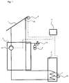
- FIG. 1 shows a solar thermal system of the prior art, which consists essentially of a solar collector 1, a solar station 2, a regulator 3, an expansion vessel 4, a pump 5, a memory 6 and a heat exchanger 7.
- a temperature measurement T 2 at the memory 6 by means of temperature sensor 10 and a temperature measurement T 1 on the solar collector 1 is carried out using the temperature sensor.
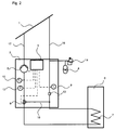
- FIG. 2 shown solar thermal system for carrying out the method according to the invention shows a solar station 2, to which a solar collector 1 and a Storage device 6 are connected.
- the solar station 2 includes in a unit a flow line 16 and a return line 17. Between the flow line 16 and the return line 17 is a bypass line 18.
- a switching valve 8 in the return line 17 can be switched such that the solar collector 1 either with the bypass line 18th or connected to the storage device 6.
- In the return line 17 is also a pump 5 and a temperature sensor 10.
- In the flow is a temperature sensor 9.
- the switching valve 8 and / or the pump 5 could also be located in the flow line 16.
- the memory 6 and the solar collector 1 is flowed through as in a conventional system of the solar fluid, in a further position, the memory 6 is bypassed via the bypass line 18 and only flows through the solar collector 1, so that the solar fluid is pumped by the pump only through the solar collector 1 and not through the memory 6.
- a storage charge does not take place in this state, but a collector temperature measurement is possible in this phase in the solar station 2.
- the conventional solar thermal systems conventional solar collector sensor for the temperature measurement on the solar collector can be omitted.
- the switching valve 8 When starting the pump 5, the switching valve 8 is in the position in which the solar fluid is not pumped through the memory 6, but through the bypass line 18. Only after the temperature measured by means of the temperature sensor 9 exceeds a predetermined temperature T L in the flow, the changeover valve 8 switches to storage charge. Thus, no unnecessary cooling takes place in the memory 6.
- the return temperature of the memory 6 is measured in the solar station 2 by the temperature measured by means of temperature sensor 10 is detected after a certain period of time. Since the memory 6 has a very sluggish temperature behavior, can via the return temperature, which is measured in the solar station 2, the Shutdown of the pump 5 can be realized. The shutdown of the pump 5 is dependent on the one hand on the difference between the collector temperature T 1 (flow) and the storage temperature T 2 (return), and on the other - on the absolute value of the measured temperature.
- a start of the pump 5 is performed with the solar station 2 according to the invention at predefined intervals in order to measure the corresponding flow temperature in the solar station 2 can.
- the solar collector 1 flows through the solar collector.
- a subsequent possible storage charge is checked by regulation 3.
- a certain minimum running time of the pump 5 can be taken into account, so that the entire system is purged for a certain time.
- FIG. 3 is a solar thermal system shown according to a further embodiment, in addition to the solar thermal system from the FIG. 2 various settings by means of a control unit with displays 19 integrated in the solar station 2 can be made and displayed.
- the solar thermal plant in the FIG. 4 has in addition to the operating unit with display 19 via a pressure sensor 11, both being integrated in the solar station 2. With the pressure sensor 11 pressure measurements to increase the reliability can be made.
- FIG. 5 shows a further embodiment of the solar thermal system.
- This system has only one temperature sensor 9, arranged in the flow line 16 downstream of the solar collector. 1
- FIGs 2-5 is also an expansion vessel 4 shown with a safety valve 14 which is connected to the flow line 16 or the return line 17. This ensures a stable pressure behavior of the solar fluid in the system.
- a first circuit of the solar collector 1 and the solar station 2 and a second circuit of the solar collector 1, the solar station 2 and the memory 6 is formed.
- the pump is switched off and the changeover valve 8 is switched such that the heat transfer medium flows only through the solar collector 1.
- the switching valve 8 is switched so that the heat transfer medium also flows through the memory 6 and a storage charge can be carried out.
- the pump 5 is turned off.
- the switching valve 8 is again switched such that the bypass line 18, the supply line 16 connects to the return line 17 and the pump 5 is turned on again.
- a speed control of the pump is conceivable at this point.
- different temperature values or temperature changes would cause different rotational speeds of the pump.
- a speed control can take place in addition to the temperature control.
- the solar station acts as the main station, as a so-called "master”.
- the solar station according to the invention can function as a slave station, as a so-called “slave”, if further control components are used in the overall system.
Landscapes
- Engineering & Computer Science (AREA)
- Chemical & Material Sciences (AREA)
- Sustainable Development (AREA)
- Sustainable Energy (AREA)
- Physics & Mathematics (AREA)
- Thermal Sciences (AREA)
- Life Sciences & Earth Sciences (AREA)
- Combustion & Propulsion (AREA)
- Mechanical Engineering (AREA)
- General Engineering & Computer Science (AREA)
- Heat-Pump Type And Storage Water Heaters (AREA)
- Central Heating Systems (AREA)
- Engine Equipment That Uses Special Cycles (AREA)
- Domestic Hot-Water Supply Systems And Details Of Heating Systems (AREA)
Description
- Die Erfindung bezieht sich auf ein Verfahren zum Betrieb einer solarthermische Anlage.
- Ein Verfahren gemäß dem Oberbegriff von Anspruch 1 ist aus dem Dokument
FR2496847 - Eine solarthermische Anlage besteht grundsätzlich aus Solarkollektoren, welche die Sonnenenergie einfangen und an ein Wärmeträgermedium (z.B. Wasser-Glykol, Wasser-Ethanol oder Wasser) abgeben, einem oder mehrere Speicher und einem geschlossenen Kreislauf, der die im Solarkollektor aufgenommene Wärme zum Speicher transportiert, einer Regelung, die die Umwälzung des Wärmeträgermediums (Sole), bei entsprechenden Temperaturdifferenzen von dem Solarkollektor zum Speicher steuert. Die Sole wird durch die Sonnenstrahlung im Solarkollektor erwärmt und dann über den Solekreislauf dem Speicher zugeführt. Anschließend kann die Sonnenwärme zum Beispiel zur Warmwasserbereitung, Heizungsunterstützung oder Schwimmbaderwärmung genutzt werden.
- Meistens ist ein einfacher Temperaturdifferenzregler für die Regelung einer kleinen solarthermischen Anlage zur Warmwasserbereitung ausreichend. Der Regler stellt über zwei Temperaturfühler fest, wann die Temperatur am Kollektoraustritt höher als die auf der Höhe des Solarkreis-Wärmetauschers gemessene Temperatur im Speicher ist und setzt daraufhin die Solarkreis-Umwälzpumpe in Betrieb. Üblicherweise werden die Solarregler so eingestellt, dass eine Temperaturdifferenz von etwa 5 - 8 K zwischen dem Solarkollektor und dem Speicher für den Pumpenstart gewährleistet ist. Sinkt diese üblicherweise um 2 bis 3 K ab, wird die Umwälzpumpe durch den Solarregler wieder außer Betrieb genommen. Trotz dieser Einstellung des Solarreglers können Probleme beim Start der Anlage auftreten, in dem die Anlage gar nicht startet oder zu früh abschaltet. So gelangt nach dem Pumpenstart kalte Flüssigkeit in den Solarkollektor, die diesen durchströmt und erhitzt wieder verlässt. Demzufolge fällt die Temperatur im Kollektor wieder rapide ab. Aufgrund der nun vorliegenden Temperaturdifferenz kann es gemäß dem Stand der Technik zum Abschalten der Pumpe kommen. Läuft die Pumpe weiter, so steigt die Temperatur wieder an, da die heiße Flüssigkeit, welche beim Pumpenstart im Solarkollektor verweilte, nach dem Durchströmen des Speichers wieder in den Solarkollektor einströmt. Erst nach einigen Umwälzungen stellt sich ein quasi-stationärer Zustand ein.
- Ein weiteres Problem bei herkömmlichen solarthermischen Anlagen besteht darin, dass die Hydraulik- und die Reglerkomponenten nicht in einer Baueinheit angeordnet sind und daher eine Vorverdrahtung der Anlage zur Erleichterung der Montage nur teilweise möglich ist.
- Aus
FR 2496847 - Der Erfindung liegt die Aufgabe zugrunde, ein gegenüber dem Stand der Technik verbessertes Verfahren für eine solarthermische Anlage zur Verfügung zu stellen, wodurch die Installation der solarthermischen Anlage vereinfacht und der Betrieb optimiert wird.
- Erfindungsgemäß wird dies gemäß den Merkmalen des Anspruchs 1 mit einem Verfahren zum Betrieb einer solarthermischen Anlage gelöst, bei dem das zu erwärmende Wärmeträgermedium mittels einer Pumpe in einem Kreislauf zwischen einer Speichervorrichtung und mindestens einem Solarkollektor über eine Vorlauf- und eine Rücklaufleitung befördert wird, wobei die Vorlauf- und die Rücklaufleitung über ein Umschaltventil und eine Bypassleitung verbindbar sind, mit einem ersten Temperatursensor angeordnet zwischen dem Solarkollektor und dem Speicher in der Vorlaufleitung stromab des Solarkollektors sowie einem zweiten Temperatursensor in der Rücklaufleitung mit folgenden Verfahrensschritten:
- nach dem Start der Pumpe ist das Umschaltventil derart geschaltet, dass das Wärmeträgermedium über die Vorlaufleitung, die Bypassleitung und die Rücklaufleitung zum Solarkollektor strömt,
- die mittels des ersten Temperatursensors gemessene Temperatur T1 wird erfasst,
- überschreitet die gemessene Temperatur T1 einen vordefinierten Temperaturwert TL, so wird das Umschaltventil derart umgeschaltet, dass das Wärmeträgermedium vom Solarkollektor zum Speicher anstelle durch die Bypassleitung strömt,
- eine mittels des zweiten Temperatursensors gemessene Temperatur T2 wird dann nach einer festgelegten Zeit t1 erfasst,
- die Differenz ΔT der erfassten Temperaturwerte T1 und T2 wird gebildet,
- wenn die Temperaturdifferenz ΔT kleiner eines vorgegebenen Wertes ΔTStop ist, wird die Pumpe abgeschaltet.
- Hierzu ist vorteilhafterweise eine Solarstation zum Anschluss mindestens eines Solarkollektors und eines Speichers derartig aufgebaut, dass sie in einer einzigen Baueinheit eine Regelung und Vorlauf- und Rücklaufleitungen enthält, wobei Temperaturfühler in jeder der Leitungen und eine Pumpe in einer der Leitungen angeordnet sind.
- Bei der solarthermischen Anlage sind die einzelnen Hydraulikkomponenten, Aktoren, Sensoren und Regler örtlich in einer Solarstation zusammengelegt, so dass eine Vorverdrahtung der Solarstation ab Werk möglich ist. Somit wird die Installationszeit weitgehend auf den hydraulischen Anschluss des Solarkollektors und des Warmwasserspeichers reduziert und eventuelle Fehler während der Installation vermieden. Weiterhin werden die Wartung und die Instandsetzung der Anlage vereinfacht.
- Besonders vorteilhaft durch die Anordnung des Kollektorfühlers in der Solarstation ist die vereinfachte elektrische und hydraulische Installation der Anlage. Diese resultiert aus der Position des Kollektorfühlers im Vorlauf der solarthermischen Anlage, wodurch ein eventuelles Vertauschen der Vor- und Rücklaufleitung zum bzw. vom Kollektor bei der Installation keine Auswirkung auf den Temperaturfühler hat. Der Temperaturfühler ist immer im Vorlauf der Solarstation angeordnet und wird immer von einer Flüssigkeit durchströmt, die erst durch den Kollektor geströmt ist, d.h. vorgewärmt ist. Eine Auswirkung auf das Verhalten der Regelung, durch vertauschte Vor- und Rücklaufleitungen, ist damit ausgeschlossen.
- Bei einer Solaranlage nach dem Stand der Technik hingegen führt das Vertauschen der Vor- und Rücklaufleitungen zu erheblichen Problemen. Zunächst wird ein Erwärmen im Kollektor durch die Sonnenstrahlung von dem Kollektorfühler registriert und die Pumpe wird gestartet. Durch die vertauschten Vor- und Rücklaufleitungen gelangt kaltes Wärmeträgermedium direkt aus dem Rücklauf zum Kollektorfühler ohne vorher das Kollektorfeld durchströmt und sich dabei erwärmt zu haben. Die Anlage schaltet wegen einer zu geringen Temperaturdifferenz zwischen Vorlauf- und Rücklauftemperatur ab.
- Mit der erfindungsgemäßen Anordnung des Temperaturfühlers wird ein solches Verhalten verhindert.
- Mit dem erfindungsgemäßen Verfahren werden Anlagenstarts vermieden, die zu keinem anschließend längeren Pumpenlauf und somit immer zu einer Speicherkühlung führen.
- Die Installation und somit die Fehleranfälligkeit der Anlage werden einerseits durch eine einfache Bedieneroberfläche mit möglichst wenigen notwendigen Einstellmöglichkeiten, andererseits durch eine Reduzierung der elektrisch und hydraulisch zu installierenden Komponenten erreicht.
- Weiterhin erfolgt die Temperaturerfassung des Solarkreisvorlaufs und -rücklaufs im System möglichst nah am zu beladenden Solarspeicher, so dass eine effiziente Energieeinlagerung in den Solarspeicher gewährleistet werden kann.
- Weitere vorteilhafte Ausgestaltungen der Erfindung ergeben sich aus den Merkmalen der abhängigen Ansprüche und der Beschreibung. Die Erfindung wird nun anhand der Figuren näher erläutert. Hierbei zeigen
- Figur 1
- eine solarthermische Anlage nach dem Stand der Technik,
- Figur 2
- eine solarthermische Anlage nach einem ersten Ausführungsbeispiel,
- Figur 3
- eine solarthermische Anlage nach einem zweiten Ausführungsbeispiel,
- Figur 4
- eine solarthermische Anlage nach einem dritten Ausführungsbeispiel und
- Figur 5
- eine solarthermische Anlage nach einem vierten Ausführungsbeispiel.
-
Figur 1 zeigt eine solarthermische Anlage aus dem Stand der Technik, die sich im Wesentlichen aus einem Solarkollektor 1, einer Solarstation 2, einem Regler 3, einem Ausdehnungsgefäß 4, einer Pumpe 5, einem Speicher 6 und einem Wärmetauscher 7 zusammensetzt. Eine Temperaturmessung T2 am Speicher 6 erfolgt mittels Temperaturfühler 10 bzw. eine Temperaturmessung T1 am Solarkollektor 1 erfolgt mithilfe des Temperaturfühlers 9. - Die in
Figur 2 dargestellte solarthermische Anlage zur Durchführung des erfindungsgemäßen Verfahrens zeigt eine Solarstation 2, an welche ein Solarkollektor 1 und eine Speichervorrichtung 6 angeschlossen sind. Die Solarstation 2 beinhaltet in einer Baueinheit eine Vorlaufleitung 16 und eine Rücklaufleitung 17. Zwischen der Vorlaufleitung 16 und der Rücklaufleitung 17 befindet sich eine Bypassleitung 18. Ein Umschaltventil 8 in der Rücklaufleitung 17 kann derart umgeschaltet werden, dass der Solarkollektor 1 entweder mit der Bypassleitung 18 oder mit der Speichervorrichtung 6 verbunden wird. In der Rücklaufleitung 17 befindet sich ferner eine Pumpe 5 und ein Temperaturfühler 10. Im Vorlauf befindet sich ein Temperaturfühler 9. Prinzipiell könnten sich das Umschaltventil 8 und / oder die Pumpe 5 auch in der Vorlaufleitung 16 befinden. - In einer ersten Stellung des Umschaltventils 8, wird der Speicher 6 sowie der Solarkollektor 1 wie bei einer gewöhnlichen Anlage von der Solarflüssigkeit durchströmt, in einer weiteren Stellung wird der Speicher 6 über die Bypassleitung 18 umgangen und nur den Solarkollektor 1 durchströmt, so dass die Solarflüssigkeit durch die Pumpe nur durch den Solarkollektor 1 und nicht durch den Speicher 6 gepumpt wird. Eine Speicherladung findet in diesem Zustand nicht statt, eine Kollektortemperaturmessung ist aber in dieser Phase in der Solarstation 2 möglich. Somit kann der bei herkömmlichen solarthermischen Anlagen übliche Solarkollektorfühler für die Temperaturmessung am Solarkollektor entfallen.
- Beim Start der Pumpe 5 befindet sich das Umschaltventil 8 in der Stellung, in der die Solarflüssigkeit nicht durch den Speicher 6, sondern durch die Bypassleitung 18 gepumpt wird. Erst nachdem die mittels des Temperaturfühlers 9 gemessene Temperatur eine vorgegebene Temperatur TL im Vorlauf überschreitet, schaltet das Umschaltventil 8 auf Speicherladung um. Somit findet keine unnötige Abkühlung im Speicher 6 statt.
- Nach der Umschaltung wird nach einer gewissen Zeitspanne die Rücklauftemperatur des Speichers 6 in der Solarstation 2 gemessen, indem die mittels Temperaturfühler 10 gemessene Temperatur erfasst wird. Da der Speicher 6 ein sehr träges Temperaturverhalten aufweist, kann über die Rücklauftemperatur, welche in der Solarstation 2 gemessen wird, die Abschaltung der Pumpe 5 realisiert werden. Die Abschaltung der Pumpe 5 ist zum einen von der Differenz zwischen der Kollektortemperatur T1 (Vorlauf) und der Speichertemperatur T2 (Rücklauf) abhängig, und zum anderen - von dem absoluten Wert der gemessenen Temperatur.
- Alle vorher fest gelegten Werte können bei einer selbstlernenden Regelung auch während des Betriebs automatisch optimiert werden.
- Ein Start der Pumpe 5 wird mit der erfindungsgemäßen Solarstation 2 in vordefinierten zeitlichen Abständen durchgeführt, um die entsprechende Vorlauftemperatur in der Solarstation 2 messen zu können. Bei einem solchen Start wird den Solarkollektor 1 mit der Solarflüssigkeit durchströmt. Eine anschließende mögliche Speicherladung wird von der Regelung 3 überprüft. Hierbei kann eine gewisse Mindestlaufzeit der Pumpe 5 beachtet werden, damit das gesamte System für eine gewisse Zeit durchspült wird.
- In
Figur 3 ist eine solarthermische Anlage nach einem weiteren Ausführungsbeispiel dargestellt, bei der zusätzlich zur solarthermischen Anlage aus derFigur 2 diverse Einstellungen mittels einer Bedieneinheit mit Displays 19 integriert in der Solarstation 2 vorgenommen und angezeigt werden können. - Die solarthermische Anlage in der
Figur 4 verfügt zusätzlich zu der Bedieneinheit mit Display 19 über einen Drucksensor 11, wobei beide in der Solarstation 2 integriert sind. Mit dem Drucksensor 11 können Druckmessungen zur Erhöhung der Betriebssicherheit vorgenommen werden. - Der
Figur 5 ist ein weiteres Ausführungsbeispiel der solarthermischen Anlage zu entnehmen. Diese Anlage hat nur einen Temperaturfühler 9, angeordnet in der Vorlaufleitung 16 stromab des Solarkollektors 1. - In
Figuren 2-5 ist auch ein Ausdehnungsgefäß 4 mit einem Sicherheitsventil 14 dargestellt, das mit der Vorlaufleitung 16 oder der Rücklaufleitung 17 verbunden ist. Damit wird ein stabiles Druckverhalten der Solarflüssigkeit in der Anlage gewährleistet. - Bei einem bevorzugten Regelungsablauf der solarthermischen Anlage wird ein erster Kreislauf aus dem Solarkollektor 1 und der Solarstation 2 sowie ein zweiter Kreislauf aus dem Solarkollektor 1, der Solarstation 2 und dem Speicher 6 gebildet. Im Fall des ersten Kreislaufs ist die Pumpe ausgeschaltet und das Umschaltventil 8 derart geschaltet, dass das Wärmeträgermedium nur durch den Solarkollektor 1 strömt. Beim zweiten Kreislauf ist die Pumpe 5 angeschaltet und nach Erreichen einer bestimmten Vorlauftemperatur wird das Umschaltventil 8 umgeschaltet, so dass das Wärmeträgermedium auch durch den Speicher 6 strömt und eine Speicherladung erfolgen kann. Nachdem die gebildete Temperaturdifferenz zwischen der Vorlauf- und Rücklauftemperatur einen bestimmten Wert unterschritten hat, wird die Pumpe 5 ausgeschaltet. Nach einer definierten Zeit nach Abschaltung der Pumpe 5 wird das Umschaltventil 8 wieder derart geschaltet, dass die Bypassleitung 18 die Vorlaufleitung 16 mit der Rücklaufleitung 17 verbindet und die Pumpe 5 wieder angeschaltet wird.
- Auch eine Drehzahlregelung der Pumpe ist an dieser Stelle denkbar. Hierzu würden verschiedene Temperaturwerte bzw. Temperaturänderungen unterschiedliche Drehzahlen der Pumpe bewirken. Somit kann eine Drehzahlregelung ergänzend zur Temperaturregelung stattfinden.
- Bei weiteren denkbaren Ausführungsbeispielen z.B. bei solarthermischen Anlagen mit einer Verbindung z.B. über ein elektronisches Bus-System zu anderen solchen Anlagen fungiert die Solarstation als Hauptstation, als so genannter "Master". Genauso kann die erfindungsgemäße Solarstation als Nebenstation, als so genannter "Slave" fungieren, wenn weitere Regelungskomponenten in dem Gesamtsystem eingesetzt werden.
- Mit den solarthermischen Anlage und Verfahren kann mehr Energie in den Speicher gespeichert werden, als bei der Regelung über eine Speichertemperatur, wie es bei herkömmlichen Anlagen üblich ist.
-
- Solarkollektor (1)
- Solarstation (2)
- Regler (3)
- Ausdehnungsgefäß (4)
- Pumpe (5)
- Speicher (6)
- Wärmetauscher (7)
- Umschaltventil (8)
- Temperaturfühler Vorlauf (9)
- Temperaturfühler Rücklauf (10)
- Drucksensor (11)
- Volumenstromfühler (12)
- Mikroblasenabscheider (13)
- Sicherheitsventil (14)
- Entlüfter (15)
- Vorlaufleitung (16)
- Rücklaufleitung (17)
- Bypassleitung (18)
- Bedieneinheit mit Display (19)
Claims (2)
- Verfahren zum Betrieb einer solarthermischen Anlage, bei dem das zu erwärmende Wärmeträgermedium mittels einer Pumpe (5) in einem Kreislauf zwischen einer Speichervorrichtung (6) und mindestens einem Solarkollektor (1) über eine Vorlauf- und eine Rücklaufleitung (16, 17) befördert wird, wobei die Vorlauf- und die Rücklaufleitung (16, 17) über ein Umschaltventil (8) und eine Bypassleitung (18) verbindbar sind, mit einem ersten Temperatursensor (9) angeordnet zwischen dem Solarkollektor (1) und dem Speicher (6) in der Vorlaufleitung (16) stromab des Solarkollektors (1) sowie einem zweiten Temperatursensor (10) in der Rücklaufleitung (17) mit folgenden Verfahrensschritten:- vor dem Start der Pumpe (5) ist das Umschaltventil (8) derart geschaltet, dass das Wärmeträgermedium über die Vorlaufleitung (16), die Bypassleitung (18) und die Rücklaufleitung (17) zum Solarkollektor (1) strömt,- dann wird die Pumpe gestartet,- die mittels des ersten Temperatursensors (9) gemessene Temperatur T1 wird erfasst,- überschreitet die gemessene Temperatur T1 einen vordefinierten Temperaturwert TL, so wird das Umschaltventil (8) derart umgeschaltet, dass das Wärmeträgermedium vom Solarkollektor (1) zum Speicher (6) anstelle durch die Bypassleitung (18) strömt,- eine mittels des zweiten Temperatursensors (10) gemessene Temperatur T2 wird erfasst,- die Differenz ΔT der erfassten Temperaturwerte T1 und T2 wird gebildet,- wenn die Temperaturdifferenz ΔT kleiner eines vorgegebenen Wertes ΔTStop ist, wird die Pumpe (5) abgeschaltet,dadurch gekennzeichnet dass, die die gemessenen Temperatur T2 nach einer festgelegten Zeit t1 erfasst wird.
- Verfahren nach Anspruch 1, dadurch gekennzeichnet, dass sofort oder nach einer definierten Zeit t2 nach Abschaltung der Pumpe (5) das Umschaltventil (8) derart geschaltet wird, dass die Bypassleitung (18) die Vorlaufleitung (16) mit der Rücklaufleitung (17) verbindet und die Pumpe (5) wieder angeschaltet wird.
Applications Claiming Priority (2)
| Application Number | Priority Date | Filing Date | Title |
|---|---|---|---|
| DE102007030363 | 2007-06-29 | ||
| AT13282007 | 2007-08-27 |
Publications (3)
| Publication Number | Publication Date |
|---|---|
| EP2009359A2 EP2009359A2 (de) | 2008-12-31 |
| EP2009359A3 EP2009359A3 (de) | 2014-08-13 |
| EP2009359B1 true EP2009359B1 (de) | 2016-09-14 |
Family
ID=39926606
Family Applications (1)
| Application Number | Title | Priority Date | Filing Date |
|---|---|---|---|
| EP08011307.9A Not-in-force EP2009359B1 (de) | 2007-06-29 | 2008-06-21 | Verfahren zum Betrieb einer solarthermischen Anlage |
Country Status (3)
| Country | Link |
|---|---|
| EP (1) | EP2009359B1 (de) |
| DE (1) | DE102008029527A1 (de) |
| ES (1) | ES2606049T3 (de) |
Families Citing this family (7)
| Publication number | Priority date | Publication date | Assignee | Title |
|---|---|---|---|---|
| DE202010010743U1 (de) | 2010-07-28 | 2011-11-11 | Robert Bosch Gmbh | Solaranlage |
| EP2551604A1 (de) | 2011-07-29 | 2013-01-30 | Robert Bosch GmbH | Solaranlage |
| DE102013111627A1 (de) | 2013-10-22 | 2015-06-03 | Viessmann Werke Gmbh & Co Kg | Verfahren zum Betrieb einer Solaranlage |
| ES2540939B1 (es) * | 2013-12-13 | 2016-04-26 | Abengoa Solar New Technologies S.A. | Planta de generación directa de vapor y procedimiento de operación de la planta |
| DE102015222909A1 (de) | 2015-11-20 | 2017-05-24 | Vaillant Gmbh | Verfahren zur Bestimmung des Frostschutzmittelgehalts eines Wärmeträgermediums in einem hydraulischen Kreislauf eines Heizsystems |
| WO2017088019A1 (en) * | 2015-11-26 | 2017-06-01 | Nivaru B.V. | A heat transfer circuit and a valve for use therein |
| DE102016112784A1 (de) * | 2016-07-12 | 2018-01-18 | Viessmann Werke Gmbh & Co Kg | Kollektorfeld, Energieversorgungssystem mit einem Kollektorfeld sowie Verfahren zum Betreiben eines Energieversorgungssystems |
Family Cites Families (7)
| Publication number | Priority date | Publication date | Assignee | Title |
|---|---|---|---|---|
| DE2907657A1 (de) * | 1979-02-27 | 1980-08-28 | Messerschmitt Boelkow Blohm | Solaranlage fuer die direkte brauchwassererwaermung |
| FR2496847A1 (fr) * | 1980-12-19 | 1982-06-25 | Mecelec Sa | Perfectionnements aux installations de chauffage utilisant la chaleur rayonnee par le soleil |
| IT8321749U1 (it) * | 1983-05-05 | 1984-11-05 | Baldini Alessandro | Unita' modulare di controllo e pompaggio per centrali termiche e simili. |
| DE19643530A1 (de) * | 1996-10-23 | 1998-10-29 | Esaa Boehringer Gmbh | Steuerung zur Erhöhung des Anlagenwirkungsgrades thermischer Solaranlagen mit Bypass-Schaltung im Kollektorkreis und diskontinuierlichem Pumpenbetrieb |
| DE29722530U1 (de) * | 1997-12-19 | 1998-06-10 | Ulrich Brunner Ofen- und Heiztechnik Gesellschaft für Guß- und Stahlkonstruktionen mbH, 84307 Eggenfelden | Heizungssteuerungsanlage |
| DE20103062U1 (de) * | 2001-02-21 | 2002-07-04 | Alfons Renn GmbH, 87474 Buchenberg | Verteilerstation für eine Heizungs- und Wasserversorgungsanlage |
| AT412505B (de) * | 2003-04-09 | 2005-03-25 | Siemens Ag Oesterreich | Solaranlage |
-
2008
- 2008-06-21 EP EP08011307.9A patent/EP2009359B1/de not_active Not-in-force
- 2008-06-21 DE DE102008029527A patent/DE102008029527A1/de not_active Withdrawn
- 2008-06-21 ES ES08011307.9T patent/ES2606049T3/es active Active
Also Published As
| Publication number | Publication date |
|---|---|
| EP2009359A2 (de) | 2008-12-31 |
| ES2606049T3 (es) | 2017-03-17 |
| DE102008029527A1 (de) | 2009-01-02 |
| EP2009359A3 (de) | 2014-08-13 |
Similar Documents
| Publication | Publication Date | Title |
|---|---|---|
| EP2009359B1 (de) | Verfahren zum Betrieb einer solarthermischen Anlage | |
| EP2806168B1 (de) | Umwälzpumpenaggregat und solarthermische Anlage damit | |
| DE10231877A1 (de) | Konstanttemperaturflüssigkeitszirkuliervorrichtung | |
| EP1950499B1 (de) | Verfahren zum Betrieb einer solarthermischen Anlage | |
| DE2507281A1 (de) | Elektrische zentral-speicherheizung | |
| EP2000742B1 (de) | Mischeinrichtung zur Einstellung der Warmwassertemperatur | |
| EP2667104A2 (de) | Anlage sowie Verfahren zur Erwärmung von Trinkwasser | |
| EP2213952A2 (de) | Solarheizanlage, Verfahren und Vorrichtung zur Diagnose einer Luftmenge in einem mit einem Solarlfuid befüllten Solarfluidkreis und zum Betreiben einer Solarheizanlage | |
| DE3441912A1 (de) | Verfahren zum automatischen abtauen eines luftbeaufschlagten verdampfers einer waermepumpe | |
| EP1160515B1 (de) | Heizungsanlage mit mindestens zwei Heizkreisen | |
| DE102006028521A1 (de) | Heizanlage und Verfahren zum Betreiben einer solchen Heizanlage | |
| DE102007033564B3 (de) | Verfahren zum Betreiben eines Schichtladespeichers und Trinkwarmwassersystem | |
| EP3385624A1 (de) | Verfahren zum betreiben einer heiz - und brauchwasseranlage, steuer - und/oder regelvorrichtung für eine heiz- und brauchwasseranlage und heiz- und brauchwasseranlage | |
| DE102005035821B3 (de) | Thermische Solaranlage | |
| EP2551604A1 (de) | Solaranlage | |
| DE2948088A1 (de) | Einrichtung zum kuehlen und beheizen von druckfluessigkeiten | |
| EP0936415B1 (de) | Warmwasser-Versorgungsanlage | |
| WO2012045108A2 (de) | Vorrichtung zum erwärmen von brauchwasser | |
| EP1953460B1 (de) | Solarregelung | |
| DE3429405C2 (de) | ||
| DE3021276C2 (de) | Elektrische Kaffee- oder Teemaschine | |
| EP2339247A2 (de) | Verfahren zur Erwärmung von Brauchwasser | |
| EP2463593A1 (de) | Verfahren zum Betrieb einer Heizungsanlage | |
| EP0405136A2 (de) | Einrichtung zur Warmwasserbereitstellung | |
| EP2218972A2 (de) | Verfahren zum Betreiben einer Heizanlage sowie Heizanlage |
Legal Events
| Date | Code | Title | Description |
|---|---|---|---|
| PUAI | Public reference made under article 153(3) epc to a published international application that has entered the european phase |
Free format text: ORIGINAL CODE: 0009012 |
|
| AK | Designated contracting states |
Kind code of ref document: A2 Designated state(s): AT BE BG CH CY CZ DE DK EE ES FI FR GB GR HR HU IE IS IT LI LT LU LV MC MT NL NO PL PT RO SE SI SK TR |
|
| AX | Request for extension of the european patent |
Extension state: AL BA MK RS |
|
| RIC1 | Information provided on ipc code assigned before grant |
Ipc: F24D 19/10 20060101AFI20131108BHEP |
|
| PUAL | Search report despatched |
Free format text: ORIGINAL CODE: 0009013 |
|
| AK | Designated contracting states |
Kind code of ref document: A3 Designated state(s): AT BE BG CH CY CZ DE DK EE ES FI FR GB GR HR HU IE IS IT LI LT LU LV MC MT NL NO PL PT RO SE SI SK TR |
|
| AX | Request for extension of the european patent |
Extension state: AL BA MK RS |
|
| RIC1 | Information provided on ipc code assigned before grant |
Ipc: F24D 19/10 20060101AFI20140704BHEP |
|
| 17P | Request for examination filed |
Effective date: 20150210 |
|
| RBV | Designated contracting states (corrected) |
Designated state(s): AT BE BG CH CY CZ DE DK EE ES FI FR GB GR HR HU IE IS IT LI LT LU LV MC MT NL NO PL PT RO SE SI SK TR |
|
| AKX | Designation fees paid |
Designated state(s): AT BE BG CH CY CZ DE DK EE ES FI FR GB GR HR HU IE IS IT LI LT LU LV MC MT NL NO PL PT RO SE SI SK TR |
|
| AXX | Extension fees paid |
Extension state: MK Extension state: AL Extension state: RS Extension state: BA |
|
| GRAP | Despatch of communication of intention to grant a patent |
Free format text: ORIGINAL CODE: EPIDOSNIGR1 |
|
| INTG | Intention to grant announced |
Effective date: 20160421 |
|
| GRAS | Grant fee paid |
Free format text: ORIGINAL CODE: EPIDOSNIGR3 |
|
| GRAA | (expected) grant |
Free format text: ORIGINAL CODE: 0009210 |
|
| AK | Designated contracting states |
Kind code of ref document: B1 Designated state(s): AT BE BG CH CY CZ DE DK EE ES FI FR GB GR HR HU IE IS IT LI LT LU LV MC MT NL NO PL PT RO SE SI SK TR |
|
| REG | Reference to a national code |
Ref country code: GB Ref legal event code: FG4D Free format text: NOT ENGLISH |
|
| REG | Reference to a national code |
Ref country code: CH Ref legal event code: EP |
|
| REG | Reference to a national code |
Ref country code: IE Ref legal event code: FG4D Free format text: LANGUAGE OF EP DOCUMENT: GERMAN |
|
| REG | Reference to a national code |
Ref country code: AT Ref legal event code: REF Ref document number: 829440 Country of ref document: AT Kind code of ref document: T Effective date: 20161015 |
|
| REG | Reference to a national code |
Ref country code: DE Ref legal event code: R096 Ref document number: 502008014624 Country of ref document: DE |
|
| REG | Reference to a national code |
Ref country code: LT Ref legal event code: MG4D |
|
| REG | Reference to a national code |
Ref country code: NL Ref legal event code: MP Effective date: 20160914 |
|
| PG25 | Lapsed in a contracting state [announced via postgrant information from national office to epo] |
Ref country code: LT Free format text: LAPSE BECAUSE OF FAILURE TO SUBMIT A TRANSLATION OF THE DESCRIPTION OR TO PAY THE FEE WITHIN THE PRESCRIBED TIME-LIMIT Effective date: 20160914 Ref country code: FI Free format text: LAPSE BECAUSE OF FAILURE TO SUBMIT A TRANSLATION OF THE DESCRIPTION OR TO PAY THE FEE WITHIN THE PRESCRIBED TIME-LIMIT Effective date: 20160914 Ref country code: NO Free format text: LAPSE BECAUSE OF FAILURE TO SUBMIT A TRANSLATION OF THE DESCRIPTION OR TO PAY THE FEE WITHIN THE PRESCRIBED TIME-LIMIT Effective date: 20161214 Ref country code: HR Free format text: LAPSE BECAUSE OF FAILURE TO SUBMIT A TRANSLATION OF THE DESCRIPTION OR TO PAY THE FEE WITHIN THE PRESCRIBED TIME-LIMIT Effective date: 20160914 |
|
| PG25 | Lapsed in a contracting state [announced via postgrant information from national office to epo] |
Ref country code: SE Free format text: LAPSE BECAUSE OF FAILURE TO SUBMIT A TRANSLATION OF THE DESCRIPTION OR TO PAY THE FEE WITHIN THE PRESCRIBED TIME-LIMIT Effective date: 20160914 Ref country code: NL Free format text: LAPSE BECAUSE OF FAILURE TO SUBMIT A TRANSLATION OF THE DESCRIPTION OR TO PAY THE FEE WITHIN THE PRESCRIBED TIME-LIMIT Effective date: 20160914 Ref country code: LV Free format text: LAPSE BECAUSE OF FAILURE TO SUBMIT A TRANSLATION OF THE DESCRIPTION OR TO PAY THE FEE WITHIN THE PRESCRIBED TIME-LIMIT Effective date: 20160914 Ref country code: GR Free format text: LAPSE BECAUSE OF FAILURE TO SUBMIT A TRANSLATION OF THE DESCRIPTION OR TO PAY THE FEE WITHIN THE PRESCRIBED TIME-LIMIT Effective date: 20161215 |
|
| REG | Reference to a national code |
Ref country code: ES Ref legal event code: FG2A Ref document number: 2606049 Country of ref document: ES Kind code of ref document: T3 Effective date: 20170317 |
|
| PG25 | Lapsed in a contracting state [announced via postgrant information from national office to epo] |
Ref country code: EE Free format text: LAPSE BECAUSE OF FAILURE TO SUBMIT A TRANSLATION OF THE DESCRIPTION OR TO PAY THE FEE WITHIN THE PRESCRIBED TIME-LIMIT Effective date: 20160914 Ref country code: RO Free format text: LAPSE BECAUSE OF FAILURE TO SUBMIT A TRANSLATION OF THE DESCRIPTION OR TO PAY THE FEE WITHIN THE PRESCRIBED TIME-LIMIT Effective date: 20160914 |
|
| REG | Reference to a national code |
Ref country code: FR Ref legal event code: PLFP Year of fee payment: 10 |
|
| PG25 | Lapsed in a contracting state [announced via postgrant information from national office to epo] |
Ref country code: CZ Free format text: LAPSE BECAUSE OF FAILURE TO SUBMIT A TRANSLATION OF THE DESCRIPTION OR TO PAY THE FEE WITHIN THE PRESCRIBED TIME-LIMIT Effective date: 20160914 Ref country code: IS Free format text: LAPSE BECAUSE OF FAILURE TO SUBMIT A TRANSLATION OF THE DESCRIPTION OR TO PAY THE FEE WITHIN THE PRESCRIBED TIME-LIMIT Effective date: 20170114 Ref country code: BG Free format text: LAPSE BECAUSE OF FAILURE TO SUBMIT A TRANSLATION OF THE DESCRIPTION OR TO PAY THE FEE WITHIN THE PRESCRIBED TIME-LIMIT Effective date: 20161214 Ref country code: PL Free format text: LAPSE BECAUSE OF FAILURE TO SUBMIT A TRANSLATION OF THE DESCRIPTION OR TO PAY THE FEE WITHIN THE PRESCRIBED TIME-LIMIT Effective date: 20160914 Ref country code: PT Free format text: LAPSE BECAUSE OF FAILURE TO SUBMIT A TRANSLATION OF THE DESCRIPTION OR TO PAY THE FEE WITHIN THE PRESCRIBED TIME-LIMIT Effective date: 20170116 Ref country code: SK Free format text: LAPSE BECAUSE OF FAILURE TO SUBMIT A TRANSLATION OF THE DESCRIPTION OR TO PAY THE FEE WITHIN THE PRESCRIBED TIME-LIMIT Effective date: 20160914 |
|
| REG | Reference to a national code |
Ref country code: DE Ref legal event code: R097 Ref document number: 502008014624 Country of ref document: DE |
|
| PLBE | No opposition filed within time limit |
Free format text: ORIGINAL CODE: 0009261 |
|
| STAA | Information on the status of an ep patent application or granted ep patent |
Free format text: STATUS: NO OPPOSITION FILED WITHIN TIME LIMIT |
|
| PG25 | Lapsed in a contracting state [announced via postgrant information from national office to epo] |
Ref country code: DK Free format text: LAPSE BECAUSE OF FAILURE TO SUBMIT A TRANSLATION OF THE DESCRIPTION OR TO PAY THE FEE WITHIN THE PRESCRIBED TIME-LIMIT Effective date: 20160914 |
|
| 26N | No opposition filed |
Effective date: 20170615 |
|
| PG25 | Lapsed in a contracting state [announced via postgrant information from national office to epo] |
Ref country code: SI Free format text: LAPSE BECAUSE OF FAILURE TO SUBMIT A TRANSLATION OF THE DESCRIPTION OR TO PAY THE FEE WITHIN THE PRESCRIBED TIME-LIMIT Effective date: 20160914 |
|
| PG25 | Lapsed in a contracting state [announced via postgrant information from national office to epo] |
Ref country code: MC Free format text: LAPSE BECAUSE OF FAILURE TO SUBMIT A TRANSLATION OF THE DESCRIPTION OR TO PAY THE FEE WITHIN THE PRESCRIBED TIME-LIMIT Effective date: 20160914 |
|
| REG | Reference to a national code |
Ref country code: CH Ref legal event code: PL |
|
| GBPC | Gb: european patent ceased through non-payment of renewal fee |
Effective date: 20170621 |
|
| REG | Reference to a national code |
Ref country code: IE Ref legal event code: MM4A |
|
| PG25 | Lapsed in a contracting state [announced via postgrant information from national office to epo] |
Ref country code: LU Free format text: LAPSE BECAUSE OF NON-PAYMENT OF DUE FEES Effective date: 20170621 Ref country code: IE Free format text: LAPSE BECAUSE OF NON-PAYMENT OF DUE FEES Effective date: 20170621 Ref country code: GB Free format text: LAPSE BECAUSE OF NON-PAYMENT OF DUE FEES Effective date: 20170621 Ref country code: CH Free format text: LAPSE BECAUSE OF NON-PAYMENT OF DUE FEES Effective date: 20170630 Ref country code: LI Free format text: LAPSE BECAUSE OF NON-PAYMENT OF DUE FEES Effective date: 20170630 |
|
| REG | Reference to a national code |
Ref country code: BE Ref legal event code: MM Effective date: 20170630 |
|
| REG | Reference to a national code |
Ref country code: FR Ref legal event code: PLFP Year of fee payment: 11 |
|
| PG25 | Lapsed in a contracting state [announced via postgrant information from national office to epo] |
Ref country code: BE Free format text: LAPSE BECAUSE OF NON-PAYMENT OF DUE FEES Effective date: 20170630 |
|
| PG25 | Lapsed in a contracting state [announced via postgrant information from national office to epo] |
Ref country code: MT Free format text: LAPSE BECAUSE OF FAILURE TO SUBMIT A TRANSLATION OF THE DESCRIPTION OR TO PAY THE FEE WITHIN THE PRESCRIBED TIME-LIMIT Effective date: 20160914 |
|
| PG25 | Lapsed in a contracting state [announced via postgrant information from national office to epo] |
Ref country code: HU Free format text: LAPSE BECAUSE OF FAILURE TO SUBMIT A TRANSLATION OF THE DESCRIPTION OR TO PAY THE FEE WITHIN THE PRESCRIBED TIME-LIMIT; INVALID AB INITIO Effective date: 20080621 |
|
| PG25 | Lapsed in a contracting state [announced via postgrant information from national office to epo] |
Ref country code: CY Free format text: LAPSE BECAUSE OF NON-PAYMENT OF DUE FEES Effective date: 20160914 |
|
| PGFP | Annual fee paid to national office [announced via postgrant information from national office to epo] |
Ref country code: IT Payment date: 20210630 Year of fee payment: 14 Ref country code: FR Payment date: 20210630 Year of fee payment: 14 |
|
| PGFP | Annual fee paid to national office [announced via postgrant information from national office to epo] |
Ref country code: AT Payment date: 20210531 Year of fee payment: 14 Ref country code: TR Payment date: 20210601 Year of fee payment: 14 |
|
| PGFP | Annual fee paid to national office [announced via postgrant information from national office to epo] |
Ref country code: ES Payment date: 20210701 Year of fee payment: 14 |
|
| PGFP | Annual fee paid to national office [announced via postgrant information from national office to epo] |
Ref country code: DE Payment date: 20220519 Year of fee payment: 15 |
|
| REG | Reference to a national code |
Ref country code: AT Ref legal event code: MM01 Ref document number: 829440 Country of ref document: AT Kind code of ref document: T Effective date: 20220621 |
|
| PG25 | Lapsed in a contracting state [announced via postgrant information from national office to epo] |
Ref country code: FR Free format text: LAPSE BECAUSE OF NON-PAYMENT OF DUE FEES Effective date: 20220630 Ref country code: AT Free format text: LAPSE BECAUSE OF NON-PAYMENT OF DUE FEES Effective date: 20220621 |
|
| PG25 | Lapsed in a contracting state [announced via postgrant information from national office to epo] |
Ref country code: IT Free format text: LAPSE BECAUSE OF NON-PAYMENT OF DUE FEES Effective date: 20220621 |
|
| REG | Reference to a national code |
Ref country code: ES Ref legal event code: FD2A Effective date: 20230731 |
|
| PG25 | Lapsed in a contracting state [announced via postgrant information from national office to epo] |
Ref country code: ES Free format text: LAPSE BECAUSE OF NON-PAYMENT OF DUE FEES Effective date: 20220622 |
|
| REG | Reference to a national code |
Ref country code: DE Ref legal event code: R119 Ref document number: 502008014624 Country of ref document: DE |
|
| PG25 | Lapsed in a contracting state [announced via postgrant information from national office to epo] |
Ref country code: DE Free format text: LAPSE BECAUSE OF NON-PAYMENT OF DUE FEES Effective date: 20240103 |
|
| PG25 | Lapsed in a contracting state [announced via postgrant information from national office to epo] |
Ref country code: TR Free format text: LAPSE BECAUSE OF NON-PAYMENT OF DUE FEES Effective date: 20220621 |