EP2008847A1 - Rollo mit Mitteln zur Verlangsamung der Aufwicklung und entsprechendes Beförderungsmittel - Google Patents
Rollo mit Mitteln zur Verlangsamung der Aufwicklung und entsprechendes Beförderungsmittel Download PDFInfo
- Publication number
- EP2008847A1 EP2008847A1 EP08159133A EP08159133A EP2008847A1 EP 2008847 A1 EP2008847 A1 EP 2008847A1 EP 08159133 A EP08159133 A EP 08159133A EP 08159133 A EP08159133 A EP 08159133A EP 2008847 A1 EP2008847 A1 EP 2008847A1
- Authority
- EP
- European Patent Office
- Prior art keywords
- fabric
- roller blind
- draw bar
- winding
- blind
- Prior art date
- Legal status (The legal status is an assumption and is not a legal conclusion. Google has not performed a legal analysis and makes no representation as to the accuracy of the status listed.)
- Granted
Links
Images


Classifications
-
- B—PERFORMING OPERATIONS; TRANSPORTING
- B60—VEHICLES IN GENERAL
- B60J—WINDOWS, WINDSCREENS, NON-FIXED ROOFS, DOORS, OR SIMILAR DEVICES FOR VEHICLES; REMOVABLE EXTERNAL PROTECTIVE COVERINGS SPECIALLY ADAPTED FOR VEHICLES
- B60J7/00—Non-fixed roofs; Roofs with movable panels, e.g. rotary sunroofs
- B60J7/0007—Non-fixed roofs; Roofs with movable panels, e.g. rotary sunroofs moveable head-liners, screens, curtains or blinds for ceilings
- B60J7/0015—Non-fixed roofs; Roofs with movable panels, e.g. rotary sunroofs moveable head-liners, screens, curtains or blinds for ceilings roller blind
Definitions
- the field of the invention is that of roller blinds, especially for motor vehicles. More specifically, the invention relates to the optimization of folding operations and / or deployment of the fabric of a roller blind whose movement is motorized.
- the roller blinds comprise a winding tube, or roller tube, on which the shade cloth is mounted.
- This tube is urged by a return torque which tends to wind the fabric around the tube so as, on the one hand to stretch the fabric when it is deployed and, on the other hand to help the winding, or folding, curtain.
- the latter allows to bring back the free end thereof, usually equipped with a pull bar, to the edges of a slot through which the fabric can circulate.
- This slot is for example made either in a housing in which the winding tube is rotatably mounted, or directly in the lining of the inside of the vehicle, the blind being mounted inside the latter, or in (or under) the rear shelf of the vehicle.
- the return torque is generated by a helical coil spring or a coil spring.
- This spring extends inside the winding tube and is secured by one of its ends to the tube, and at its other end to a fixed structural element, integral with the housing or the frame on which is mounted the winding tube.
- This return torque must be large enough to stretch the fabric, to allow a complete winding of the fabric, and to press the draw bar against its support, when the blind is folded, so as to avoid shocks and unwanted noise when the vehicle is moving.
- roller blinds have motorized deployment and winding.
- the ends of the draw bar slide in rails. Cables running in these rails and linked to the ends of the draw bar, can pull or push it in one direction or the other.
- a motor usually electric, acts on these cables so to draw or push the draw bar in a balanced way at both ends.
- a geared motor can be used at the output of the electric motor.
- the electric motor can actuate the deployment or winding of the roller blind by acting on its draw bar.
- this motor In the direction of deployment of the fabric, this motor must act against the action of the return torque generated by the spring located in the roller tube.
- the action generated by the motor goes in the same direction as the return torque.
- the load to which the electric motor is subjected is therefore much lower in the direction of winding than in the direction of deployment of the blind.
- the return torque may be sufficient to bring back the drawing bar alone by winding the fabric or, on the contrary, be insufficient to counteract the friction forces of the ends of the draw bar in the rails.
- the motor by acting on the draw bar through the cables, pulls the draw bar to ensure the winding of the blinds.
- the spring of the return torque then serves essentially to maintain the stretched fabric during its winding. If instead, the force generated by the return torque is greater than the friction forces at the ends of the draw bar, the motor, which will be actuated to wind the fabric, will then turn empty. It may then race, producing an unpleasant noise due to the excitement of the engine games, and risking excessive heating.
- the action of the return springs located in the su-blind case is generally linear.
- this force can be of the order of 100 N.
- a first phase during which the forces of the return spring will be greater than the friction forces of the ends of the pull rod in the rails, a second phase, in which these forces will be substantially balanced, and a third phase, during which the forces of reminder will be lower than the friction forces and where the motor effort will be required to complete the winding.
- This configuration can therefore lead, in the first and second phase, on the one hand unpleasant noises when the engine works off load and therefore rotates at an excessive speed and secondly, a risk of damage to the engine. It can also cause non-regular engine noise, depending on whether it works with a greater or lesser load.
- the document DE-20 2007 005531 proposes another solution, consisting in associating with guiding shoes of a draw bar in rails a leaf spring, whose particular shape generates a friction in the rails during the folding of the fabric, to oppose the withdrawal. .
- this approach is complex to implement and adjust, due to the shape of the spring and its association with the pad, and generates unacceptable friction noises.
- friction, lower also exist during the deployment of the canvas, which is of course not desirable.
- the invention particularly aims to overcome these disadvantages of the prior art.
- the invention aims to provide a roller blind that avoids, or at least limit, the problems associated with the winding too fast blind, while maintaining a sufficient tension of the return means.
- the invention also aims to provide such a blind whose engine runs more regularly.
- the invention aims to provide a blind making the least noise possible during its deployment and its winding, and whose noise is as regular as possible.
- Another object of the invention is to limit the risk of deterioration of the electric motor of such a blind, and to allow a more economical dimensioning of this motor.
- a particular object of the invention is to limit the energy consumption by the awning during its deployment and its winding.
- the invention also aims to avoid vibrations or jolts during movement of the pulling bar of the blind, and to maintain homogeneous speed of these movements.
- the invention also aims to provide such a blind that is simple to manufacture and easy to implement, and whose manufacture does not generate significant additional costs.
- a roller blind for a motor vehicle comprising an integral blackout fabric at a first end of a winding tube carrying first means of return of the fabric in a position in which the fabric is wound, and at a second end of a draw bar, the ends of this draw bar being slidably guided in rails during the movement of the fabric and driven by means of motorized actuation of the draw bar, comprising at least one cable element.
- this blind comprises slowing means acting on at least one of said cable elements, so as to oppose the movement of the draw bar during the winding of the fabric.
- the awning winding is slowed down, when the fabric is folded, which avoids the deterioration of the motor and the excessive noise due to too fast winding.
- this slowing down at the operating means of the draw bar has the effect of improving the tension of the shade cloth.
- the slowing means comprise friction means in contact with at least one element of the motorized actuating means.
- the slowing means comprise a grease retarder.
- Such a retarder makes it possible to apply a perfectly regular and controlled slowing down to the pull bar.
- the slowing means are arranged so as not to oppose the movement of the draw bar during deployment of the fabric.
- the deceleration then occurs only during the winding of the fabric, which has the effect of not increasing the load of the engine during the deployment of the fabric.
- the energy required for deployment is therefore not increased, and the motor load is better distributed between the different operating phases.
- the blind comprises selective connection means between the motorized actuating means and the slowing means, providing a connection only during the winding of the fabric.
- the selective connection means comprise a unidirectional clutch.
- This embodiment allows a simple and effective implementation of the slowdown opposing the movement of the draw bar only during winding.
- the slowing means comprise second return means opposing the force applied to the fabric by the first biasing means.
- This embodiment makes it possible, on the one hand, to slow down the draw bar during winding of the blind, and on the other hand to store the energy corresponding to this slowing down so as to restore it when the blind is deployed.
- the engine can thus operate more smoothly, and its maximum load is reduced, which leads to a reduction in its energy consumption and the possibility of sizing it more economically.
- the roller blind according to the invention is suitable for at least one of the uses among the concealment of a side window of a motor vehicle, the concealment of a rear window of a motor vehicle, the occultation a glazed flag of a motor vehicle and the luggage cover.
- the invention also relates to a motor vehicle comprising at least one roller blind as described above.
- the Figures 1 and 2 illustrate an example of a roller blind whose deployment and winding are motorized. More specifically, the figure 1 represents such a blind in wound position (or whose canvas, or blackout fabric, or occulting fabric, is in the wound position), and the figure 2 represents it in deployed position.
- the roller tube 12 of the blind is attached to a frame 14 surrounding the area to be obscured.
- the lateral portions of this frame 14, between which the fabric 11 must unfold, carry rails 141 and 142.
- These rails 141 and 142, or slides, are provided for sliding the ends, respectively 131 and 132, of the bar 13, which are shaped slider form adapted to slide in the rails 141 and 142.
- the rails 141 and 142 are traversed by actuating cables that move the ends 131 and 133 of the draw bar 13.
- the figure 3 represents a mechanism for actuating the cables 30 which is carried by the portion of the frame 14 located near the roller tube 12.
- the actuating cables 31 and 32 and the actuating mechanism of the cables 30 form motorized actuating means of the blind. These figures show the free portions of the cables 31 and 32, which are not included between the drive mechanism 30 and the ends 131 and 132 of the pull bar.
- These cables 31 and 32 are of the type "push-pull” (English: push-pull), which means that they can be used to actuate a movement in both traction and compression. Their second ends, which are not represented on the figure 3 are connected to the ends 131 and 132 of the draw bar 13.
- the cables circulate, between the actuating mechanism 30 and the rails 141 and 142 respectively, in guiding sheaths 331 and 332, respectively, which, as may be seen in FIG. see on Figures 1 and 2 are, in turn, carried by the frame 14.
- the cables respectively 31 and 32 are guided so as not to be able to escape from the rail, even when they are stressed in compression.
- the actuating mechanism of the cables 30 comprises a gear pinion 34 which is actuated by an electric motor 6.
- This pinion gear 34 is engaged with both the cables 31 and 32.
- the cables 31 and 32 comprise in effect, threads, or grooves along their perimeter, which allow them to be engaged with the gear pinion 34.
- the cables 31 and 32 are engaged in the actuating mechanism 30 in different directions, and that each of these cables is engaged with one side of the gear pinion 34.
- the electric motor 6, by actuating the gear pinion 34 can simultaneously push the two cables 31 and 32, or on the contrary pull at the same time these two cables.
- This simultaneous actuation of the two cables 31 and 32 makes it possible to ensure that the draw bar 13 is pushed or pulled in a balanced manner at each of its ends and that it will thus maintain a balanced position, substantially perpendicular to the direction of rotation. unwinding the awning.
- the invention proposes to create new loads for the motor, applied to the actuation cable or cables ( or at least one of the cables), in the winding phase, in order to tend towards a standardization of the motor loads in these different phases.
- a first possible embodiment of the invention is to add friction in the sliding system of the draw bar 13 in the rails 141 and 142. These friction can be implemented either at the sliding between the draw bar and the rails, ie at the level of the circulation of the cables 31 and 32.
- a change of material and / or diameter of the cables may also make it possible to increase the friction between the cables and the surrounding parts (in particular the guiding sheaths 331 and 332 and the rails 141 and 142). Finally, it is also possible to add a zone specifically assigned to friction against the cable, in order to add friction.
- This first embodiment only partially achieves the objectives of the invention. Thus, it may have the effect, if the friction and the adjustment of the spring are adapted, to prevent the electric motor works "empty" during the winding of the fabric. However, an increase in friction will also result in the work force required by the motor during the deployment of the awning will be greater. There will thus remain a great disparity between the work required by the engine during deployment and during winding of the blind.
- a grease retarder 4 In a second embodiment represented by the figures 4 and 5 the actuating mechanism of the cables 30 is modified in order to add a grease retarder 4.
- a grease retarder 4 well known to those skilled in the art, is represented on the figure 5 . It comprises a gear pinion 41, similar to the gear pinion 34, connected to the electric motor, of the actuating mechanism 30.
- the grease retarder 4 can advantageously be placed between the two cables 31 and 32, next to the pinion gear 34 linked to the electric motor.
- the pinion 41 may, like the pinion 34, be in engagement with both the cables 31 and 32.
- a housing 42 which has attachment tabs 421, for fixing the housing to the frame 14.
- elements, such as blades, driven by the pinion gear 41 rotate, together with the gear pinion, in a bath of grease.
- the friction generated by this rotation in the grease has the effect of slowing the rotation of the pinion 41.
- the pinion 41 is connected to the elements rotating in the grease by a unidirectional clutch (not visible in the figures).
- a unidirectional clutch well known to those skilled in the art, allows to ensure that the pinion can rotate freely in one direction without driving the rotating elements in the fat bath, and therefore without being slowed down. On the contrary, it drives the rotating elements in the fat bath, and is therefore slowed down, when it turns in the other direction.
- the grease retarder 4 mounted appropriately next to the pinion gear 34 connected to the electric motor makes it possible to ensure that, during the deployment of the awning cloth, the electric motor has to provide only the force required for this purpose. deployment, the pinion 41 rotating freely.
- the grease retarder engages, in order to slow down this winding. This slowdown generates a higher load for the electric motor, which no longer works underload.
- This embodiment therefore allows a standardization of the load of the motor between the phases of unfolding the awning and winding thereof, without further charging the engine during deployment.
- this solution does not cause any annoying effect for the taut aspect of the fabric, the braking acting at the draw bar and not at the roller tube of the blind.
- the blades rotating in the grease of the retarder may be shaped to oppose a large resistance in one direction of rotation and a low or almost zero resistance in the other direction of rotation .
- the use of a one-way clutch is then no longer necessary to implement the invention.
- FIG. 6 A third embodiment of the invention is shown on the Figures 6 and 7 .
- the figure 6 represents the underside of the portion of a frame 14 similar to that shown on the figure 4 . It can be seen the cables 31 and 32 and the guiding sheaths 331 and 332, it can also see the motor 6 which actuates the gear pinion 34 (not visible on the figure 6 ).
- the grease retarder of the figure 4 has been replaced by a spiral spring system.
- This spring system comprises a gear pinion not visible on the figure 6 , similar to the gear pinion 41 of the figure 4 .
- This pinion gear is connected to one end of a spiral spring such as that shown on the figure 7 .
- the other end of this spiral spring 7 is connected to the frame 14.
- the spring system is installed so that the action of the spring opposes the movement of the cables causing the winding of the blind fabric, and that it tends to assist the movements of the cables tending to deploy the awning fabric.
- This spring 7 therefore has the effect of tending towards a uniformization of the effort required of the electric motor between the phases of deployment and winding of the fabric, by accumulating energy during winding and restoring it during deployment.
- a spring 7 is used which has characteristics complementary to those of the return spring located in the winding tube.
- this solution does not involve any risk of deterioration of the stretched appearance of the fabric.
- the action of the spring 7 occurs at the pull bar and not the winder.
- the spring 7 tends to move the draw bar of the winder, the two springs thus exert their actions on the fabric in opposite directions.
- the present invention can be applied to all blinds or occulters used in motor vehicles, such as side window blinds or rear roof. It is more particularly applicable to blinds obscuring glass pavilions of motor vehicles, or luggage covers, which extend horizontally. These blinds indeed require, to be stretched correctly, to be pulled by particularly powerful return springs, which can aggravate the disadvantages present in the prior art.
- the electric motors 6 used to actuate blinds or occulators of the vehicles are current type motors, having a housing connected to the motor stator and a shaft, or motor shaft, one end of which is connected to the rotor of the motor and the other end is free. This free end is, when mounting the motor, connected to a gear pinion 34 to actuate the blind.
- gear gear 34 may move away from the workpiece (or one of the parts) with which it must be engaged, and gear teeth to be skipped during operation of the gear. engine. This game can also cause, if it is too important, a slip of the gear.
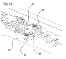
- This maintenance is performed using a flange 8, shown on the Figures 8 to 10 .
- the flange 8 is fixed by means of screws 82 and 83 passing through corresponding holes 86 and 87 of the flange, to a fixed element 81 of the drive mechanism 30.
- This flange 8 covers the upper end 10 of the motor shaft of the motor 6 or, which is equivalent, the gear gear mounted on this upper end.
- the flange 8 comprises, in the axis of the motor shaft, a recess 85.
- the end 10 of the shaft also comprises a recess 101, located opposite the recess 85 of the flange 8.
- These two recesses 85 and 101 are intended to maintain a ball 9 between the flange 8 and the end 10 of the drive shaft, aligned with the axis of rotation of the latter.
- the flange 8 is mounted so as to be slightly deformed to leave room for the ball 9.
- it acts as a spring pressing the ball 9 against the end 10 of the motor shaft.
- the combined action of the flange 8 and the ball 9 has the effect of centering the end 10 of the motor shaft, whose axis of rotation is maintained so as to pass through the ball 9 and the recess 85 of the
- the flange 8 has the effect of pressing the end of the motor shaft and prevent the movement of the shaft in the direction of its axis of rotation.
Applications Claiming Priority (2)
| Application Number | Priority Date | Filing Date | Title |
|---|---|---|---|
| FR0756049A FR2917998A1 (fr) | 2007-06-26 | 2007-06-26 | Store a enrouleur a moyens de ralentissement de l'enroulement et vehicule correspondant. |
| FR0757548 | 2007-09-13 |
Publications (2)
| Publication Number | Publication Date |
|---|---|
| EP2008847A1 true EP2008847A1 (de) | 2008-12-31 |
| EP2008847B1 EP2008847B1 (de) | 2009-12-23 |
Family
ID=39832196
Family Applications (1)
| Application Number | Title | Priority Date | Filing Date |
|---|---|---|---|
| EP20080159133 Expired - Fee Related EP2008847B1 (de) | 2007-06-26 | 2008-06-26 | Rollo mit Mitteln zur Verlangsamung der Aufwicklung und entsprechendes Beförderungsmittel |
Country Status (2)
| Country | Link |
|---|---|
| EP (1) | EP2008847B1 (de) |
| DE (1) | DE602008000436D1 (de) |
Cited By (1)
| Publication number | Priority date | Publication date | Assignee | Title |
|---|---|---|---|---|
| CN102733747A (zh) * | 2011-04-07 | 2012-10-17 | 宝适汽车部件(太仓)有限公司 | 用于机动车辆的卷帘组件 |
Citations (7)
| Publication number | Priority date | Publication date | Assignee | Title |
|---|---|---|---|---|
| DE4320393A1 (de) * | 1993-06-19 | 1994-12-22 | Webasto Karosseriesysteme | Bremsvorrichtung |
| EP1112876A2 (de) * | 1999-12-27 | 2001-07-04 | Webasto Vehicle Systems International GmbH | Sonnenschutzvorrichtung für einen lichtdurchlässigen Fahrzeugdachbereich |
| DE10163122A1 (de) * | 2001-12-20 | 2003-07-10 | Bos Gmbh | Doppelrollo für gekrümmte Scheiben |
| DE102005048207B3 (de) * | 2005-10-07 | 2006-11-23 | Webasto Ag | Rolloanordnung für ein Kraftfahrzeug |
| DE102006004139A1 (de) * | 2005-07-14 | 2007-01-25 | Webasto Ag | Rollosystem mit gebremstem Gleiter |
| DE202007005531U1 (de) | 2007-04-17 | 2007-06-14 | Arvinmeritor Gmbh | Rollosystem, insbesondere für ein Schiebedach |
| DE102006023813A1 (de) * | 2006-05-20 | 2007-11-22 | Daimlerchrysler Ag | Rollosystem mit Querspannung |
-
2008
- 2008-06-26 DE DE200860000436 patent/DE602008000436D1/de active Active
- 2008-06-26 EP EP20080159133 patent/EP2008847B1/de not_active Expired - Fee Related
Patent Citations (7)
| Publication number | Priority date | Publication date | Assignee | Title |
|---|---|---|---|---|
| DE4320393A1 (de) * | 1993-06-19 | 1994-12-22 | Webasto Karosseriesysteme | Bremsvorrichtung |
| EP1112876A2 (de) * | 1999-12-27 | 2001-07-04 | Webasto Vehicle Systems International GmbH | Sonnenschutzvorrichtung für einen lichtdurchlässigen Fahrzeugdachbereich |
| DE10163122A1 (de) * | 2001-12-20 | 2003-07-10 | Bos Gmbh | Doppelrollo für gekrümmte Scheiben |
| DE102006004139A1 (de) * | 2005-07-14 | 2007-01-25 | Webasto Ag | Rollosystem mit gebremstem Gleiter |
| DE102005048207B3 (de) * | 2005-10-07 | 2006-11-23 | Webasto Ag | Rolloanordnung für ein Kraftfahrzeug |
| DE102006023813A1 (de) * | 2006-05-20 | 2007-11-22 | Daimlerchrysler Ag | Rollosystem mit Querspannung |
| DE202007005531U1 (de) | 2007-04-17 | 2007-06-14 | Arvinmeritor Gmbh | Rollosystem, insbesondere für ein Schiebedach |
Cited By (2)
| Publication number | Priority date | Publication date | Assignee | Title |
|---|---|---|---|---|
| CN102733747A (zh) * | 2011-04-07 | 2012-10-17 | 宝适汽车部件(太仓)有限公司 | 用于机动车辆的卷帘组件 |
| CN102733747B (zh) * | 2011-04-07 | 2016-12-14 | 宝适汽车部件(太仓)有限公司 | 用于机动车辆的卷帘组件 |
Also Published As
| Publication number | Publication date |
|---|---|
| EP2008847B1 (de) | 2009-12-23 |
| DE602008000436D1 (de) | 2010-02-04 |
Similar Documents
| Publication | Publication Date | Title |
|---|---|---|
| EP1582681B1 (de) | Betätigungsvorrichtung einer Tür, Benutzung einer Bremse in einer solchen Vorrichtung und Verfahren zur Einstellung eines Antriebsmoments in einer solchen Vorrichtung | |
| EP2371592B1 (de) | Schattenrollo für Kraftfahrzeuge mit Hemmschützmittel | |
| EP1619078B1 (de) | Rollo für Laderaumabdeckung für ein Kraftfahrzeug und hiermit ausgestattetes Fahrzeug | |
| EP2008847B1 (de) | Rollo mit Mitteln zur Verlangsamung der Aufwicklung und entsprechendes Beförderungsmittel | |
| FR2882090A1 (fr) | Dispositif d'occultation a rideau enrouleur manuel et multi position | |
| FR2917998A1 (fr) | Store a enrouleur a moyens de ralentissement de l'enroulement et vehicule correspondant. | |
| EP1637693B1 (de) | Vorrichtung zum Antrieb einer Wickelwelle eines Rolladens | |
| EP1787839B2 (de) | Fensterrollo für Motorfahrzeug mit Mitteln zur Kompensation von Spiel und korrespondierendes Fahrzeug | |
| EP1657398B1 (de) | Antriebsvorrichtung für einen Rollladenbehang | |
| FR2934202A1 (fr) | Store a enrouleur pour vehicule automobile a moyens d'equilibrage de la barre de tirage, et vehicule automobile correspondant. | |
| FR2926497A1 (fr) | Dispositif d'occultation d'une fenetre panoramique de vehicule automobile, a rideaux a coulissement commande par deux cables entraines par un moteur central | |
| FR2793836A1 (fr) | Store a enrouleur a bouchon de tube d'enroulement non coaxial | |
| FR2934203A1 (fr) | Store a enrouleur pour vehicule automobile a barre de tirage non perpendiculaire a l'axe de deplacement et vehicule correspondant. | |
| EP1433634A1 (de) | Verdunkelungsvorrichtung für Fahrzeug mit einer nicht kreisförmigen Rollvorrichtung und Fahrzeug dazu | |
| WO2017055224A1 (fr) | Dispositif d'occultation pour vehicule automobile, a courroie crantee | |
| FR2958223A1 (fr) | Store d'occultation pour vehicule automobile, a tube enrouleur portant des poulies tronconiques. | |
| FR2866293A1 (fr) | Dispositif cache-bagages pour vehicule automobile, et vehicule automobile correspondant | |
| FR3123257A3 (fr) | Store d’occultation pour véhicule automobile, à poulies hélicoïdales. | |
| FR2925102A1 (fr) | Dispositif d'occultation presentant un enrouleur galbe pour vitre ou panneau transparent, notamment pour vehicule automobile | |
| FR2925103A1 (fr) | Module d'occultation avec un support pour une surface vitree ou un panneau transparent, notamment pour vehicule automobile | |
| FR2918929A1 (fr) | Store d'occultation pour vehicule automobile, a barre de tirage basculante, et vehicule automobile correspondant | |
| FR2833535A1 (fr) | Store a enrouleur, notamment pour vehicules automobiles, destine a occulter selectivement deux portions de surface vitree, portiere et vehicule correspondants | |
| EP2080652B1 (de) | Abdeckvorrichtung mit Zugstange, die mit Ausgleichselementen ausgestattet ist, und entsprechendes Kraftfahrzeug | |
| FR2982291A1 (fr) | Velum ou banne a vague permettant un controle de la tension de la toile | |
| FR2941736A1 (fr) | Dispositif d'occultation a reglages multiples |
Legal Events
| Date | Code | Title | Description |
|---|---|---|---|
| PUAI | Public reference made under article 153(3) epc to a published international application that has entered the european phase |
Free format text: ORIGINAL CODE: 0009012 |
|
| AK | Designated contracting states |
Kind code of ref document: A1 Designated state(s): AT BE BG CH CY CZ DE DK EE ES FI FR GB GR HR HU IE IS IT LI LT LU LV MC MT NL NO PL PT RO SE SI SK TR |
|
| AX | Request for extension of the european patent |
Extension state: AL BA MK RS |
|
| 17P | Request for examination filed |
Effective date: 20090227 |
|
| GRAP | Despatch of communication of intention to grant a patent |
Free format text: ORIGINAL CODE: EPIDOSNIGR1 |
|
| GRAS | Grant fee paid |
Free format text: ORIGINAL CODE: EPIDOSNIGR3 |
|
| AKX | Designation fees paid |
Designated state(s): DE FR |
|
| GRAA | (expected) grant |
Free format text: ORIGINAL CODE: 0009210 |
|
| AK | Designated contracting states |
Kind code of ref document: B1 Designated state(s): DE FR |
|
| REF | Corresponds to: |
Ref document number: 602008000436 Country of ref document: DE Date of ref document: 20100204 Kind code of ref document: P |
|
| RAP2 | Party data changed (patent owner data changed or rights of a patent transferred) |
Owner name: ADVANCED COMFORT SYSTEMS FRANCE - ACS FRANCE |
|
| RAP2 | Party data changed (patent owner data changed or rights of a patent transferred) |
Owner name: ADVANCED COMFORT SYSTEMS FRANCE SAS - ACS FRANCE |
|
| PLBE | No opposition filed within time limit |
Free format text: ORIGINAL CODE: 0009261 |
|
| STAA | Information on the status of an ep patent application or granted ep patent |
Free format text: STATUS: NO OPPOSITION FILED WITHIN TIME LIMIT |
|
| 26N | No opposition filed |
Effective date: 20100924 |
|
| REG | Reference to a national code |
Ref country code: DE Ref legal event code: R082 Ref document number: 602008000436 Country of ref document: DE Representative=s name: EISENFUEHR, SPEISER & PARTNER, DE |
|
| REG | Reference to a national code |
Ref country code: DE Ref legal event code: R081 Ref document number: 602008000436 Country of ref document: DE Owner name: ADVANCED COMFORT SYSTEMS FRANCE SAS - ACS FRAN, FR Free format text: FORMER OWNER: ADVANCED COMFORT SYSTEMS FRANCE-ACS FRANCE, BRESSUIRE, FR Effective date: 20110913 Ref country code: DE Ref legal event code: R082 Ref document number: 602008000436 Country of ref document: DE Representative=s name: EISENFUEHR SPEISER PATENTANWAELTE RECHTSANWAEL, DE Effective date: 20110913 |
|
| REG | Reference to a national code |
Ref country code: FR Ref legal event code: PLFP Year of fee payment: 8 |
|
| PGFP | Annual fee paid to national office [announced via postgrant information from national office to epo] |
Ref country code: DE Payment date: 20150622 Year of fee payment: 8 |
|
| PGFP | Annual fee paid to national office [announced via postgrant information from national office to epo] |
Ref country code: FR Payment date: 20150624 Year of fee payment: 8 |
|
| REG | Reference to a national code |
Ref country code: DE Ref legal event code: R119 Ref document number: 602008000436 Country of ref document: DE |
|
| REG | Reference to a national code |
Ref country code: FR Ref legal event code: ST Effective date: 20170228 |
|
| PG25 | Lapsed in a contracting state [announced via postgrant information from national office to epo] |
Ref country code: FR Free format text: LAPSE BECAUSE OF NON-PAYMENT OF DUE FEES Effective date: 20160630 Ref country code: DE Free format text: LAPSE BECAUSE OF NON-PAYMENT OF DUE FEES Effective date: 20170103 |