EP2008472B1 - Séparation luminance/chrominance en vidéo - Google Patents
Séparation luminance/chrominance en vidéo Download PDFInfo
- Publication number
- EP2008472B1 EP2008472B1 EP06740755.1A EP06740755A EP2008472B1 EP 2008472 B1 EP2008472 B1 EP 2008472B1 EP 06740755 A EP06740755 A EP 06740755A EP 2008472 B1 EP2008472 B1 EP 2008472B1
- Authority
- EP
- European Patent Office
- Prior art keywords
- signal
- received
- component
- chrominance
- magnitude
- Prior art date
- Legal status (The legal status is an assumption and is not a legal conclusion. Google has not performed a legal analysis and makes no representation as to the accuracy of the status listed.)
- Not-in-force
Links
- 238000000926 separation method Methods 0.000 title description 3
- 230000000295 complement effect Effects 0.000 claims description 28
- 238000001514 detection method Methods 0.000 claims description 26
- 238000000034 method Methods 0.000 claims description 24
- 239000003638 chemical reducing agent Substances 0.000 claims description 13
- 238000012886 linear function Methods 0.000 claims description 4
- 238000001914 filtration Methods 0.000 claims description 3
- 239000004065 semiconductor Substances 0.000 claims description 2
- 241000023320 Luma <angiosperm> Species 0.000 description 92
- OSWPMRLSEDHDFF-UHFFFAOYSA-N methyl salicylate Chemical compound COC(=O)C1=CC=CC=C1O OSWPMRLSEDHDFF-UHFFFAOYSA-N 0.000 description 92
- 239000002131 composite material Substances 0.000 description 22
- 238000001228 spectrum Methods 0.000 description 20
- 230000006870 function Effects 0.000 description 11
- 238000010586 diagram Methods 0.000 description 4
- 238000012545 processing Methods 0.000 description 4
- 238000013461 design Methods 0.000 description 3
- 230000002238 attenuated effect Effects 0.000 description 2
- 238000006243 chemical reaction Methods 0.000 description 2
- 230000004044 response Effects 0.000 description 2
- 230000003068 static effect Effects 0.000 description 2
- 239000003086 colorant Substances 0.000 description 1
- 230000001419 dependent effect Effects 0.000 description 1
- 238000012544 monitoring process Methods 0.000 description 1
- 238000012552 review Methods 0.000 description 1
- 230000000007 visual effect Effects 0.000 description 1
Images
Classifications
-
- H—ELECTRICITY
- H04—ELECTRIC COMMUNICATION TECHNIQUE
- H04N—PICTORIAL COMMUNICATION, e.g. TELEVISION
- H04N11/00—Colour television systems
- H04N11/06—Transmission systems characterised by the manner in which the individual colour picture signal components are combined
- H04N11/18—Transmission systems characterised by the manner in which the individual colour picture signal components are combined using simultaneous and sequential signals, e.g. SECAM-system
- H04N11/186—Decoding means therefor
-
- H—ELECTRICITY
- H04—ELECTRIC COMMUNICATION TECHNIQUE
- H04N—PICTORIAL COMMUNICATION, e.g. TELEVISION
- H04N9/00—Details of colour television systems
- H04N9/77—Circuits for processing the brightness signal and the chrominance signal relative to each other, e.g. adjusting the phase of the brightness signal relative to the colour signal, correcting differential gain or differential phase
- H04N9/78—Circuits for processing the brightness signal and the chrominance signal relative to each other, e.g. adjusting the phase of the brightness signal relative to the colour signal, correcting differential gain or differential phase for separating the brightness signal or the chrominance signal from the colour television signal, e.g. using comb filter
Definitions
- Color television standards have progressed with an emphasis on backwards compatibility to ensure new standards will function on older black and white televisions.
- modern color television standards call for a basic black and white brightness signal, called luminance (luma), as well as a color signal, called chrominance (chroma).
- Current color television encoding processes e.g. NTSC, PAL and SECAM
- provide this color and brightness information by summing up the luma and chroma signals in an overlay frequency spectrum and results in a so-called composite signal.
- the video decoding system must separate the luma and chroma signals from the composite signal and decode these signals to obtain the video components.
- the chroma information is modulated on a subcarrier through frequency modulation, and luma information is carried in the baseband with spectrum beyond the chroma's subcarrier.
- the luma and chroma are often separated using band-trap filter and band-pass filters.
- a band-trap filter is used to suppress the chroma subcarrier to capture the luma spectrum
- the band-pass filter is used to capture the chroma spectrum.
- the quality of the image derived from the luma and chroma spectrums is dependent on the bandwidths of both the band-trap filter and the band-pass filters.
- the bandwidths of the band-trap and band-pass filters for any particular SECAM application are static values based on a design compromise between sharpness and artifacts. As a result of these static values, the ability to separate the luma and chroma signals at various points in the frequency spectrum is reduced.
- EP0597160 describes a matched filter that separates SECAM signal into various signal paths, multiburst structures and edges are detected in the SECAM signal and control the adding of the luminance highpass component to the crosstalk-free lowpass component.
- an apparatus for generating a video image the apparatus is configured to separate a video signal into a luminance component and a chrominance component, and to generate a feedforward control signal based on the amplitude of a demodulated FM signal associated with the chrominance component.
- Implementations described herein may include one or more of the following features.
- a signal adder configured to add a portion of the chrominance component to the luminance component, the amount of the chrominance component added to the luminance component may be function of the feedforward control signal.
- a signal reducer configured to remove at least a portion of the chrominance component from the video image, the amount of the chrominance component is reduced may be a function of the feedforward control signal.
- a luminance-chrominance separation device There is described herein a luminance-chrominance separation device.
- a video signal is separated into a luminance signal and a chrominance signal and a portion of the chrominance signal is fed forward into the luminance signal.
- Implementations may include one or more of the following features.
- the amount of chrominance signal fed forward into the luminance signal is based on the amplitude of a demodulated FM signal associated with the chrominance signal. A portion of the chrominance signal may be removed from a chrominance output.
- the invention provides an apparatus, for use in a receiver configured to receive an electronic video signal.
- the video signal includes a luminance component that is encoded with amplitude modulation and a chrominance component that is encoded with frequency modulation on a carrier frequency.
- the apparatus includes a variable band-trap filter device configured to receive the video signal and output a substantial portion of the luminance component as a received luminance component, a filter device configured to receive the video signal and output a substantial portion of the chrominance component as a received chrominance component, a carrier notch filter configured to receive the received chrominance component and output a complementary luminance signal, a leakage detector device configured to receive the carrier magnitude of the received chrominance component and output a leakage detection signal, and a variable signal adder configured to receive the leakage detection signal and to make a determination as to whether to add a portion of the complementary luminance signal to the received luminance component.
- the invention provides an apparatus, for use in a receiver configured to receive an electronic video signal.
- the video signal includes a first component that is encoded with amplitude modulation and a second component that is encoded with frequency modulation on a carrier frequency.
- the apparatus includes a second filter device configured to receive the video signal and output a substantial portion of the second component as a received second component, a leakage detector device configured to receive the carrier frequency of the second component and output a leakage detection signal, and a first filter device with variable trap band configured to receive the video signal and output a substantial portion of the first component.
- the variable signal adder is configured to determine a difference between the leakage detection signal and a first threshold.
- the variable signal adder is configured to add a portion of the received second component to the received first component, such that the magnitude of the received second component added to the received first component is based a lookup table which includes a value representing the difference between the leakage detection signal and the first threshold, and the magnitude of the received second component to be added to the first component.
- the magnitude of the received second component added to the received first component is proportional to the difference between the leakage detection signal and the first threshold.
- the magnitude of the received second component added to the received first component is linearly proportional to the difference between the leakage detection signal and the first threshold.
- the magnitude of the received second component added to the received first component is geometrically proportional to the difference between the leakage detection signal and the first threshold.
- the first filter device, the second filter device, the leakage detector device, and the variable signal adder are disposed on a semiconductor chip.
- implementations described herein may include a variable signal reducer configured to receive the leakage detection signal and to make a determination as to whether to reduce a portion of the received second component.
- the apparatus for use in a receiver configured to receive an electronic video signal.
- the video signal includes a first component that is encoded with amplitude modulation and a second component that is encoded with frequency modulation on a carrier frequency.
- the apparatus includes a first filter device configured to receive the video signal and output a substantial portion of the first component as a received first component, a second filter device configured to receive the video signal and output a substantial portion of the second component as a received second component, a leakage detector device configured to receive the carrier frequency of the second component and output a leakage detection signal, a demodulation device configured to demodulate the received second component and output a second component signal, and a variable signal reducer configured to receive the leakage detection signal and to make a determination as to whether to reduce a portion of the second component signal.
- variable signal reducer is configured to determine a difference between the leakage detection signal and a first threshold.
- the variable signal reducer is configured to remove a portion of the second component signal, such that the magnitude of the second component signal removed is based a lookup table which includes a value representing the difference between the leakage detection signal and the first threshold, and the magnitude of second component signal to be removed.
- the magnitude of the second component signal removed is proportional to the difference between the leakage detection signal and the first threshold. The entire second component signal may be removed.
- implementations may include a variable signal adder configured to receive the leakage detection signal and to make a determination as to whether to add a portion of the received second component to the received first component.
- the composite SECAM video signal includes an amplitude modulated luminance signal, a frequency modulated chrominance signal, and a chrominance carrier signal.
- the method includes filtering the composite SECAM video signal into a received luminance signal and a received chrominance signal, monitoring the amplitude of the chrominance carrier signal, and adding a portion of the received chrominance signal into the received luminance signal if the amplitude of the chrominance carrier signal exceeds a first threshold.
- Implementations may include one or more of the following features. Determining the magnitude of the received chrominance signal to be added to the received luminance signal based on the magnitude of the difference between the amplitude of the chrominance carrier signal and the first threshold value. Selecting the magnitude of the received chrominance signal to add to the received luminance signal from a previously stored lookup table. Calculating the magnitude of the received chrominance signal to add to the received luminance signal based on a linear function. Calculating the magnitude of the received chrominance signal to add to the received luminance signal based on a geometric function. Demodulating the received chrominance signal to produce a chrominance output.
- implementations may include one or more of the following features. Removing a portion of the chrominance output if the amplitude of the chrominance carrier signal exceeds a second threshold. Determining the magnitude of chrominance output to be removed based on the magnitude of the difference between the amplitude of the chrominance carrier signal and the second threshold value, including even reducing the chrominance output to zero.
- the composite SECAM video signal includes an amplitude modulated luminance signal, a frequency modulated chrominance signal, and a chrominance carrier signal.
- the chip includes a memory including stored instructions, and a processor coupled to the memory and configured to read the instructions from the memory to perform digital signal processing to decode the composite SECAM video signal.
- the processor will transform the composite SECAM video signal into a received luminance signal, a received chrominance signal, and a received chrominance carrier signal, monitor the amplitude of the received chrominance carrier signal, determine that the received chrominance signal includes a portion of the received luminance signal if the amplitude of the received chrominance carrier signal exceeds a first threshold value, and add a portion the received chrominance signal into the received luminance signal if the amplitude of the received chrominance carrier signal exceeds the first threshold value.
- Implementations may include one or more of the following features.
- the processor further will determine the amount of the received chrominance signal to add to the received luminance signal based on the magnitude of the difference between the received chrominance carrier signal arid the first threshold value.
- the processor further will demodulate the received chrominance signal to produce a chrominance output, and remove a portion of the chrominance output if the amplitude of the received chrominance carrier signal exceeds a second threshold value.
- the processor further will determine the amount of the chrominance output to remove based on the magnitude of the difference between the received chrominance carrier signal and the second threshold value.
- Video images can be derived from a SECAM video signal.
- the SECAM video signal can be divided into luminance and chrominance components.
- the derived video images can be adjusted by adding a portion of the chrominance component into luminance component.
- the video image can also be adjusted by removing portions of the chrominance component.
- Embodiments of the invention provide techniques for separating luminance and chrominance signal components in a composite SECAM video signal.
- Luminance luma
- Chrominance chroma
- FM Frequency Modulation
- the SECAM video signal is split into luma and chroma output.
- the luma output is produced by applying a band-trap filter to the video signal.
- the chroma carrier is isolated by applying a band-pass filter to the video signal, and the chroma output is produced by demodulating and decoding the chroma carrier.
- the amplitude of the chroma carrier is monitored during reception.
- the amplitude should remain within a nominal value. Therefore, deviations in the amplitude of the chroma carrier indicate that the luma signal is present in the chroma spectrum.
- the magnitude of the deviation in the chroma carrier amplitude is proportional to the amount of luma in the chroma spectrum. Thus, the magnitude of the deviation is compared to a threshold amplitude value. If the deviation in the chroma carrier amplitude is greater than the threshold amplitude, the value of the chroma output can be reduced.
- the trap band of the band-trap filter can be reduced, or a portion of the chroma carrier can be added to the luma.
- the respective amounts of reduction in the chroma output and increase in the luma output are preferably independently determined yet both proportional to the magnitude of the deviation in the chroma carrier amplitude.
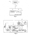
- a video system 10 for transferring visual information from one point to another includes a video signal generator 12 and a video signal receiver 14.
- the system 10 is configured to produce, transmit, receive and display video signals.
- the video signal generator 12 is configured to produce a video signal 20.
- the video signal 20 includes encoded digital and analog formats such as HDMI (digital YCbCr), DVI (digital RGB), Analog YPbPr, Analog RGB, Analog S-Video and Analog composite (e.g. NTSC, PAL and SECAM).
- the video generator 12 may be, but is not limited to, a source such as a VCR, DVD player, a channel on a local television broadcast, cable television, a satellite system, internet broadcasts, game consoles, or graphics circuits integrated in a computer.
- the generator 12 is further configured to send the signal 20, e.g. over a wire or wirelessly, to the receiver 14.
- the video signal receiver 14 is configured to receive and process the signal 20 and includes a video signal decoder 16 and a display 18.
- the video signal receiver 14 may be, but is not limited to, a device such as a television, a computer, a VCR, a digital recorder, a satellite set-top receiver, and an integrated circuit within a larger video system (e.g. multi-screen display systems, video editing equipment).
- the video signal decoder 16 and display 18 can be integrated within the video signal receiver 14, or they can be independent components which are operationally connected to the video signal receiver 14.
- the video signal decoder 16 is configured to receive and decode the signal 20 and to output a display signal 22.
- the video signal decoder 16 can transform the video signal 20 into the display signal 22.
- the video signal decoder 16 is configured to except a known video signal format (e.g. HDMI, DVI, Analog RGB, Analog composite) and output the display signal 22 to the display 18 (e.g. CRT, LCD, Plasma).
- the video signal decoder 16 may also perform digital-to-analog (D/A) conversion followed by an analog-to-digital (A/D) conversion to produce the display signal 22.
- D/A digital-to-analog
- A/D analog-to-digital
- the video signal decoder 16 includes a component for separating luma and chroma in composite SECAM formatted video signals 20.
- a composite SECAM video signal 20 includes a baseband luma signal and an FM modulated chroma signal.
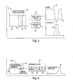
- the video signal decoder 16 includes a variable band-trap filter 42, a band-pass filter 44, a chroma signal demodulator 46a and a chroma decoder 46b, a leakage detector 50, a variable signal attenuator 54a, an adder 54b, a carrier notch filter 56, and a variable signal reducer 58.
- the video signal decoder 16 is configured to separate the luma and chroma signals, demodulate and decode the chroma signal, and depending on the quality of the separation, to adjust the bandwidth of the variable trap-band filter, add various amounts of the chroma signal to the luma signal, and to reduce the chroma signal by various amounts.
- the variable band-trap filter 42 is configured to receive and filter the video input signal 20 to remove the received chroma spectrum 32 while allowing a received luma signal 30 to pass through.
- an exemplary system 70 receives a composite video signal 20 that includes a luma spectrum 26 and a chroma spectrum 27 which is FM modulated on the chroma carrier signal 28.
- the band-trap filter 42 is configured to filter the video input signal 20 to remove its chroma signal 32 while allowing its luma signal 30 to pass through.
- the band-trap filter 42 is designed to have a frequency response that provides desired operation of the system 70.
- the band-pass filter 44 in the video signal decoder 16 is configured to receive and filter the video input signal 20 to remove the received luma spectrum while allowing the received chroma signal 32 to pass through.
- the system 70 includes a band-pass filter 44 configured to receive the composite video signal 20 and remove its luma signal while allowing its chroma signal 32 to pass through.
- the band-pass filter 44 and band-trap filter 42 are independent, e.g., the bandwidths of the pass band and trap band need not be complementary.
- the band-pass filter 44 is designed to have a bandwidth that provides desired circuit operation. If the bandwidth of the band-pass filter 44 is too wide, the decoded color may contains false color. Conversely if the bandwidth of the band-pass filter 44 is too narrow, the result image may be degraded in terms of color sharpness.
- the bandwidths for the band-trap filter 42 and the band-pass filter 44 are selected and accordingly configured to accommodate the expected range of the frequency spectrum of the video input signal 20.
- the chroma signal 32 is received by the carrier notch filter 56 and the chroma signal demodulator 46a and decoder 46b.
- the carrier notch filter 56 (e.g. a narrow notch filter) is configured to remove the chroma signal 27 which is FM modulated by carrier frequency 28 from the chroma signal 32 to reduce the "dot crawl" video artifact in the resulting video image.
- the carrier notch filter 56 outputs a complementary luma signal 55 to the variable signal attenuator 54a and adder 54b.
- the chroma signal demodulator 46a and decoder 46b are configured to receive the chroma signal 32 and to output an instantaneous chroma carrier magnitude signal 48 and a base chroma output signal 49.
- the video signal 20 includes a chroma spectrum 27 that is encoded with Frequency Modulation.
- the chroma signal demodulator 46a and decoder 46b is configured to demodulate the chroma signal 32 with a known FM demodulation technique (e.g., CORDIC, PLL, or DSP) to output the base chroma output signal 49 to the variable signal reducer 58.
- a known FM demodulation technique e.g., CORDIC, PLL, or DSP
- the chroma signal demodulator 46a and decoder 46b are also configured to monitor the amplitude of the chroma carrier signal 28 portion of the chroma signal 32 and output an instantaneous chroma carrier magnitude signal 48 to the leakage detector 50.
- the system 100 includes the instantaneous chroma carrier magnitude signal 48, the leakage detector 50, and the luma leakage indicator signal 52.
- the leakage detector 50 includes a DC removal device 120, an absolute value calculator device 130, and a low pass filter device 140.
- the leakage detector 50 is configured to provide a leak indicator signal 52 for use in determining whether too much of the luma spectrum 26 is in the chroma signal 32.
- the average magnitude signal 110 is the averaged chroma carrier magnitude 48 during colorburst.
- the DC removal device 120 subtracts the averaged chroma carrier magnitude 110 from the instantaneous chroma carrier magnitude signal 48.
- the absolute value device 130 converts deviations in the instantaneous chroma carrier magnitude signal 48 which could be below an average magnitude 110 (and thus below zero) to positive values.
- the low pass filter device 140 is to remove signal spikes from the instantaneous chroma carrier magnitude signal 48.
- the low pass filter device 140 can be implemented in a simple IIR filter or FIR filter.
- the output of the leakage detector 50 is the luma leakage indicator signal 52.
- Leakage of the luma spectrum 26 into the chroma signal 32 will cause the luma leakage indicator signal 52 to exceed a threshold value.
- the level of the deviation between the luma leakage indicator signal 52 and the threshold value is proportional to the magnitude of the luma spectrum 26 in the chroma signal 32.
- variable band-trap filter 42 in the video signal decoder 16 receives the input video signal 20 and suppresses the chroma carrier 27 to generate luma signal 30.
- the variable band-trap filter 42 is implemented using a FIR (finite impulse response) filter with programmable coefficients. Multiple sets of coefficients with different trap bands can be selected.
- the variable band-trap filter 42 is configured to compare the luma leakage indicator signal 52 to a threshold value and quantize the comparison result. The quantized comparison result is used to select different set of filter coefficients. For example, when the luma leakage indicator signal 52 is below the threshold, a set of nominal coefficients is used.
- the width of the trap band is inversely proportional to the magnitude of the difference between the leakage indicated signal 52 and the threshold value, e.g., the larger the difference, the narrower of the trap band.
- variable attenuator 54a in the video signal decoder 16 receives the complementary luma signal 55 and the luma leakage indicator signal 52.
- the variable attenuator 54a is configured to compare the luma leakage indicator signal 52 to a threshold value and inversely attenuate the complementary luma signal 55. For example, when the luma leakage indicator signal 52 is below the threshold, the complementary luma signal 55 is attenuated to zero.
- the adder 54b adds the attenuated complementary luma signal into the luma signal 30.
- the threshold value may be determined in a variety of manners, e.g., based on user preference settings (e.g., variables in a software program), or an average value based on a stochastic sample (e.g., a process feedback algorithm). Also, for example, the threshold value could be a fixed value that is integrated into the circuit design through digital or analog components.
- the variable attenuator 54a and adder 54b can calculate a difference between the luma leakage indicator signal 52 and the threshold value, and inject a portion of the complementary luma signal 55 into the luma signal 30 based on the magnitude of the difference between the leakage indicator signal 52 and the threshold value to produce a luma output signal 60.
- the magnitude of the complementary luma signal 55 added to the luma signal 30 is preferably inversely, e.g., linearly, proportional to the magnitude of the difference between the leakage indicated signal 52 and the threshold value. For example, if the deviation in the leakage indicator signal 52 and the threshold value is small, then a small amount of complementary luma signal 55 is injected into the luma spectrum to produce a slightly increased luma output signal 60. The larger the deviation, the larger is the amount of the complementary luma signal 55 injected into the luma signal 30.
- the relationship between the magnitude of the deviation and the magnitude of the injected signal need not be limited to a linear function. Other acceptable relationships include geometric, logarithmic or multivariate functions.
- the variable signal reducer 58 is configured to receive the luma leakage indicator signal 52 and the chroma output signal 49, and can compare the luma leakage indicator signal 52 to a threshold value.
- the threshold value in the variable signal reducer 58 can be independent of the threshold value used in the variable attenuator 54a.
- the threshold value in the variable signal reducer 58 may be determined in a variety of manners, e.g., based on user preference settings (e.g. a variable in a software program), or an average value based on a stochastic sample (e.g. a process feedback algorithm). Also, for example, the threshold value could be a fixed value that is integrated into the circuit design through digital or analog circuit components.
- the variable signal reducer 58 can calculate a difference between the luma leakage indicator signal 52 and the threshold value, and reduce the decoded chroma output 49 based on the magnitude of the difference between the leakage indicator signal 52 and the threshold value.
- the magnitude of the reduction in the decoded chroma output 49 is preferable directly, e.g. linearly, proportional to the magnitude of the difference between the leakage indicated signal 52 and the threshold value. For example, if the deviation in the leakage indicator signal 52 and the threshold value is small, then the decoded chroma output 49 is reduced slightly, resulting in a chroma output signal 62 that is slightly lower than the decoded chroma output 49.
- the decoded chroma output signal 49 may be reduced completely, resulting in a chroma output signal 62 of zero (i.e. no color).
- the relationship between the magnitude of the deviation and the magnitude of the chroma reduction need not be limited to a linear function. Other acceptable relationships include geometric, logarithmic or multivariate functions,
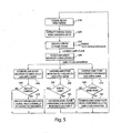
- a process 200 for separating luminance and FM chrominance signal components in a video signal using the video signal decoder 16 includes the stages shown.
- the process 200 is exemplary only and not limiting.
- the process 200 may be altered, e.g., by having stages added, removed, or rearranged.
- a SECAM video signal is received by the video signal decoder 16 and provided to the band-trap filter 42 and the band-pass filter 44.
- the SECAM video signal received at stage 210 is filtered via band-pass filter to extract chroma carrier signal 32.
- the carrier notch filter 42 removes chroma carrier frequency from the chroma carrier signal 32.
- the chroma carrier signal 32 is demodulated through FM demodulation techniques. During the demodulation, the magnitude of the amplitude of the FM carrier is generated.
- the magnitude of the amplitude of the known chroma carrier is monitored.
- the instantaneous chroma carrier magnitude signal 48 is received by the leakage detector 50 and transformed to the luma leakage indicator signal 52 via the DC removal device 120, the absolute value calculator device 130, and the low pass filter device 140.
- the DC removal device removes the DC bias in the instantaneous chroma carrier magnitude signal 48, e.g., the average magnitude 110 during colorburst.
- the absolute value calculator device 130 converts signal values that are below the average magnitude 110 to positive values to produce a signal containing all positive values.
- the low pass filter 140 removes spikes, e.g. smoothens, the signal and outputs the luma leakage indicator signal 52.
- variable signal reducer 58 compares the value of the luma leakage indicator signal 52 from the leakage detector 50 to a first threshold value. Deviations between the magnitude of the luma leakage indicator signal 52 and the first threshold value indicate that a portion of the luma spectrum 26 is leaking into the chroma signal 32 which could cause false color.
- a decision is made at stage 260 as to whether a portion of the base chroma signal 49 will be reduced. If so, stage 270 reduces decoded chroma 49 proportionally and generates chroma output 62 with reduced false color.
- the amount of the decoded chroma signal 49 reduced is preferably proportional to the magnitude of the difference between the luma leakage indicator signal 52 and the first threshold value. If the difference is small, only a small amount of decoded chroma signal 49 is reduced. The larger the difference, the larger the amount of base chroma signal 49 removed. For example, the decoded chroma output signal 49 may be reduced completely, resulting in a chroma output signal 62 with no color.
- the relationship between the magnitude of the difference and the amount of base chroma signal 49 reduced is preferably direct (e.g. linear), but other acceptable relationships can be based on user defined data tables, or other geometric, logarithmic and multivariate functions.
- variable attenuator 54a compares the values of the luma leakage indicator signal 52 from the leakage detector 50 to a second threshold value. Deviations between the magnitude of the luma leakage indicator signal 52 and the second threshold value indicate that the chroma signal 32 contains piece of luma information.
- a decision is made at stage 290 as to whether to add the complementary luma signal 55 to the luma signal 30. If so, then stage 300 adjusts the attenuation for the complementary luma signal 55 proportionally and adds it into luma signal 30 to generate the final luma output 60.
- the amount of the complementary luma signal 55 injected into the luma signal 30 is preferably proportional to the magnitude of the difference between the luma leakage indicator signal 52 and the second threshold value. If the difference is small, only a small amount of complementary luma signal 55 is injected into the luma signal 30. The larger the difference, the larger the amount of complementary luma signal 55 injected into the luma signal 32.
- the relationship between the magnitude of the difference and the amount of complementary luma signal 55 injected into the luma signal 30 is preferably direct (e.g. linear), but other acceptable relationships can be based on user defined data tables, or other geometric, logarithmic and multivariate functions.
- the variable band-trap filter 42 compares the values of the luma leakage indicator signal 52 from the leakage detector 50 to a third threshold value. Deviations between the magnitude of the luma leakage indicator signal 52 and the third threshold value indicate that a portion of the luma spectrum 26 is leaking into chroma signal. A decision is made at stage 320 as to whether to reduce the trap band of the variable band-trap filter. If so, then another set of filter coefficients corresponding to a narrower trap band are used in the trap-band filter.
Landscapes
- Engineering & Computer Science (AREA)
- Multimedia (AREA)
- Signal Processing (AREA)
- Processing Of Color Television Signals (AREA)
Claims (13)
- Appareil utilisé dans un récepteur conçu pour recevoir un signal vidéo électronique, dans lequel le signal vidéo comprend une composante de luminance qui est codée avec une modulation d'amplitude et une composante de chrominance qui est codée avec une modulation de fréquence sur une fréquence porteuse, l'appareil comprenant :un dispositif à filtre de piégeage de bande variable conçu pour recevoir le signal vidéo et pour émettre une partie importante de la composante de luminance sous la forme d'une composante de luminance reçue;un dispositif à filtre conçu pour recevoir le signal vidéo et pour émettre une partie importante de la composante de chrominance sous la forme d'une composante de chrominance reçue;un filtre à encoche porteuse conçu pour recevoir la composante de chrominance reçue et pour émettre un signal complémentaire de luminance ;un dispositif détecteur de fuite conçu pour recevoir l'amplitude de porteur de la composante de chrominance reçue et pour émettre un signal de détection de fuite ; etun additionneur de signaux variables conçu pour recevoir le signal de détection de fuite et pour déterminer s'il faut ajouter une partie du signal complémentaire de luminance à la composante de chrominance reçue;le dispositif à filtre de piégeage de bande variable étant en outre conçu pour recevoir le signal de détection de fuite, pour comparer le signal de détection de fuite à un premier seuil et pour ajuster la largeur de bande de filtration du dispositif à filtre de piégeage de bande variable en fonction de la comparaison.
- Appareil selon la revendication 1, dans lequel l'additionneur de signaux variables conçu pour déterminer s'il faut ajouter une partie du signal complémentaire de luminance à la composante de luminance reçue comprenant la détermination d'une différence entre le signal de détection de fuite et un deuxième seuil.
- Appareil selon la revendication 1, comprenant en outre un réducteur de signaux variables conçu pour recevoir le signal de détection de fuite et pour déterminer s'il faut réduire une partie de la composante de chrominance reçue.
- Appareil selon la revendication 1, dans lequel le dispositif à filtre de piégeage de bande variable, le dispositif détecteur de fuite et l'additionneur de signaux variables sont disposés sur une puce semi-conductrice.
- Procédé de réception d'un signal vidéo électronique, le signal vidéo comprenant une composante de luminance qui est codée avec une modulation d'amplitude et une composante de chrominance qui est codée avec modulation de fréquence sur une fréquence porteuse, le procédé comprenant :la réception du signal vidéo au niveau d'un dispositif à filtre de piégeage de bande variable et l'émission d'une partie importante de la composante de luminance sous la forme d'une composante de luminance reçue;la réception du signal vidéo au niveau d'un deuxième dispositif à filtre et l'émission d'une partie importante de la composante de chrominance sous la forme d'une composante de chrominance reçue;la réception de la composante reçue de chrominance au niveau d'un filtre à encoche porteuse et l'émission d'un signal complémentaire de luminance ;la réception de l'amplitude de la composante reçue de chrominance au niveau d'un dispositif détecteur de fuite et l'émission d'un signal de détection de fuite ; etla réception du signal de détection de fuite au niveau d'un additionneur variable de signaux et la détermination s'il faut ajouter une partie du signal complémentaire de luminance à la composante de luminance reçue;le dispositif à filtre de piégeage de bande variable étant en outre conçu pour recevoir le signal de détection de fuite, pour comparer le signal de détection de fuite à un premier seuil et pour ajuster la largeur de bande de filtration du dispositif à filtre de piégeage de bande variable en fonction de la comparaison.
- Procédé selon la revendication 5, dans lequel la détermination s'il faut ajouter une partie du signal complémentaire de luminance à la composante de luminance reçue comprend la détermination d'une amplitude du signal complémentaire de luminance à ajouter à la composante de luminance reçue en fonction d'une amplitude de la différence entre l'amplitude du signal de détection de fuite et un deuxième seuil.
- Procédé selon la revendication 6, dans lequel la détermination d'une amplitude comprend la sélection de l'amplitude du signal complémentaire de luminance pour ajouter à la composante de luminance reçue à partir d'un tableau de consultation préalablement enregistré.
- Procédé selon la revendication 6, dans lequel la détermination d'une amplitude comprend le calcul de l'amplitude du signal complémentaire de luminance à ajouter à la composante de luminance reçue selon une fonction linéaire.
- Procédé selon la revendication 6, dans lequel la détermination d'une amplitude comprend le calcul de l'amplitude du signal complémentaire de luminance à ajouter à la composante de luminance reçue selon une fonction géométrique.
- Procédé selon la revendication 5, comprenant en outre la démodulation de la composante reçue de chrominance pour produire une sortie de chrominance.
- Procédé selon la revendication 10, comprenant en outre l'élimination d'une partie de la sortie de chrominance si l'amplitude du signal porteur de chrominance dépasse un troisième seuil.
- Procédé selon la revendication 11, dans lequel l'élimination comprend la détermination de l'amplitude de la sortie de chrominance à éliminer en fonction de l'amplitude de la différence entre l'amplitude du signal porteur de chrominance et la troisième valeur de seuil.
- Procédé selon la revendication 12, dans lequel l'élimination comprend la réduction de la sortie de chrominance à zéro.
Applications Claiming Priority (1)
| Application Number | Priority Date | Filing Date | Title |
|---|---|---|---|
| PCT/US2006/013146 WO2007117236A1 (fr) | 2006-04-07 | 2006-04-07 | Séparation luminance/chrominance en vidéo |
Publications (2)
| Publication Number | Publication Date |
|---|---|
| EP2008472A1 EP2008472A1 (fr) | 2008-12-31 |
| EP2008472B1 true EP2008472B1 (fr) | 2015-06-03 |
Family
ID=37576985
Family Applications (1)
| Application Number | Title | Priority Date | Filing Date |
|---|---|---|---|
| EP06740755.1A Not-in-force EP2008472B1 (fr) | 2006-04-07 | 2006-04-07 | Séparation luminance/chrominance en vidéo |
Country Status (3)
| Country | Link |
|---|---|
| US (1) | US8248536B2 (fr) |
| EP (1) | EP2008472B1 (fr) |
| WO (1) | WO2007117236A1 (fr) |
Families Citing this family (2)
| Publication number | Priority date | Publication date | Assignee | Title |
|---|---|---|---|---|
| US8634766B2 (en) | 2010-02-16 | 2014-01-21 | Andrew Llc | Gain measurement and monitoring for wireless communication systems |
| US9554438B2 (en) * | 2013-12-11 | 2017-01-24 | Revolution Display, Llc | Lighting integration into video and power stream |
Citations (1)
| Publication number | Priority date | Publication date | Assignee | Title |
|---|---|---|---|---|
| US4706112A (en) * | 1986-01-31 | 1987-11-10 | Faroudja Laboratories, Inc. | Cross color suppression for quadrature modulated color television |
Family Cites Families (34)
| Publication number | Priority date | Publication date | Assignee | Title |
|---|---|---|---|---|
| GB1054441A (fr) * | 1963-01-21 | |||
| US3751581A (en) * | 1971-10-18 | 1973-08-07 | Japan Broadcasting Corp | Color television standard system converting equipment |
| FR2280279A1 (fr) * | 1974-07-26 | 1976-02-20 | Thomson Csf | Perfectionnement aux recepteurs de television en couleur du systeme secam |
| JPS5539433A (en) * | 1978-09-13 | 1980-03-19 | Toshiba Corp | Identification signal detection circuit in secam system |
| GB2110044A (en) | 1981-11-06 | 1983-06-08 | Rca Corp | Digital signal separation network and television receiver including such a network |
| FR2583246B1 (fr) * | 1985-06-11 | 1987-08-07 | Thomson Csf | Procede de separation des signaux de luminance et de chrominance d'un signal video composite pal ou secam et dispositif pour la mise en oeuvre de ce procede |
| JPH0714220B2 (ja) * | 1987-06-12 | 1995-02-15 | パイオニア株式会社 | Y/c分離回路 |
| US4922331A (en) * | 1987-06-23 | 1990-05-01 | Sony Corporation | Color video signal reproducing apparatus having trap circuit and comb-filter for filtering a chrominance signal band of a wide band luminance signal |
| KR930005626Y1 (ko) * | 1991-02-28 | 1993-08-27 | 김영선 | 탁자다리 결착장치 |
| US5233410A (en) * | 1991-08-15 | 1993-08-03 | The Grass Valley Group, Inc. | Interpolating digital signal clipping circuit and composite video clipping circuit utilizing same |
| US6392714B1 (en) * | 1991-11-15 | 2002-05-21 | Snell & Wilcox Limited | Color television signal processing |
| EP0597160A1 (fr) | 1992-11-13 | 1994-05-18 | THOMSON multimedia | Méthode et appareil de séparation luminance/chrominance |
| KR0166745B1 (ko) * | 1995-07-10 | 1999-03-20 | 김광호 | 누출성분을 제거하는 색신호 처리장치 |
| US5786871A (en) * | 1996-04-01 | 1998-07-28 | Tektronix, Inc. | Constant luminance corrector |
| GB9607592D0 (en) | 1996-04-12 | 1996-06-12 | Snell & Wilcox Ltd | Encoding and decoding of composite video signals |
| JPH09322195A (ja) * | 1996-05-31 | 1997-12-12 | Sony Corp | 信号トラップ装置および方法、記録媒体再生装置および方法、並びに信号抽出装置および方法 |
| JPH10117361A (ja) * | 1996-10-08 | 1998-05-06 | Toshiba Corp | ビデオ信号処理回路 |
| US6052157A (en) * | 1997-08-04 | 2000-04-18 | Innovision Labs | System and method for separating chrominance and luminance components of a color television system |
| GB2328336B (en) * | 1997-08-14 | 2001-10-10 | Quantel Ltd | An image processing system |
| GB2332324A (en) | 1997-12-10 | 1999-06-16 | Snell & Wilcox Ltd | Luminance and chrominance separation filter for composite video decoder |
| US6108048A (en) * | 1998-06-02 | 2000-08-22 | Ati Technologies, Inc. | System and method for compensating against false color from composite video source information |
| US6175389B1 (en) * | 1999-02-04 | 2001-01-16 | Conexant Systems, Inc. | Comb filtered signal separation |
| US6751354B2 (en) * | 1999-03-11 | 2004-06-15 | Fuji Xerox Co., Ltd | Methods and apparatuses for video segmentation, classification, and retrieval using image class statistical models |
| US6950772B1 (en) * | 2000-12-19 | 2005-09-27 | Ati International Srl | Dynamic component to input signal mapping system |
| US7082218B2 (en) * | 2001-07-27 | 2006-07-25 | Hewlett-Packard Development Company, L.P. | Color correction of images |
| EP1326433B1 (fr) * | 2001-12-29 | 2012-04-11 | Samsung Electronics Co., Ltd. | Appareil et méthode de contrôle de luminosité d'image |
| US7532254B1 (en) * | 2003-05-20 | 2009-05-12 | Pixelworks, Inc. | Comb filter system and method |
| US7420625B1 (en) * | 2003-05-20 | 2008-09-02 | Pixelworks, Inc. | Fuzzy logic based adaptive Y/C separation system and method |
| US7227585B1 (en) * | 2003-12-30 | 2007-06-05 | Conexant Systems, Inc. | Luminance and chrominance separation system |
| US7454081B2 (en) * | 2004-01-30 | 2008-11-18 | Broadcom Corporation | Method and system for video edge enhancement |
| KR101385961B1 (ko) * | 2007-12-21 | 2014-04-16 | 삼성전자주식회사 | 영상신호의 색 노이즈 제거 장치 및 방법 |
| JP4538075B1 (ja) * | 2009-02-27 | 2010-09-08 | 株式会社東芝 | クロスカラードット妨害低減回路、クロスカラードット妨害低減機能を持つ映像装置、およびクロスカラードット妨害低減方法 |
| US8830256B2 (en) * | 2009-12-23 | 2014-09-09 | Samsung Display Co., Ltd. | Color correction to compensate for displays' luminance and chrominance transfer characteristics |
| US9049410B2 (en) * | 2009-12-23 | 2015-06-02 | Samsung Display Co., Ltd. | Color correction to compensate for displays' luminance and chrominance transfer characteristics |
-
2006
- 2006-04-07 WO PCT/US2006/013146 patent/WO2007117236A1/fr active Application Filing
- 2006-04-07 US US12/296,357 patent/US8248536B2/en not_active Expired - Fee Related
- 2006-04-07 EP EP06740755.1A patent/EP2008472B1/fr not_active Not-in-force
Patent Citations (1)
| Publication number | Priority date | Publication date | Assignee | Title |
|---|---|---|---|---|
| US4706112A (en) * | 1986-01-31 | 1987-11-10 | Faroudja Laboratories, Inc. | Cross color suppression for quadrature modulated color television |
Also Published As
| Publication number | Publication date |
|---|---|
| US8248536B2 (en) | 2012-08-21 |
| WO2007117236A1 (fr) | 2007-10-18 |
| US20100045871A1 (en) | 2010-02-25 |
| EP2008472A1 (fr) | 2008-12-31 |
Similar Documents
| Publication | Publication Date | Title |
|---|---|---|
| JP2688355B2 (ja) | 標準成分カラー映像信号の処理方法 | |
| US5031030A (en) | Video signal encoded with additional detail information | |
| KR100716290B1 (ko) | 영상처리장치, 부가정보처리장치 및 영상처리방법 | |
| KR100945689B1 (ko) | 개인용 비디오 플레이어들을 위한 tv 사용자 인터페이스및 처리 | |
| KR930003178B1 (ko) | 상관적응형 휘도신호와 색신호 분리회로 | |
| WO2007109148A2 (fr) | Procédé et appareil pour détecter un mouvement selon la chrominance dans des champs d'un signal vidéo | |
| EP2008472B1 (fr) | Séparation luminance/chrominance en vidéo | |
| US6163346A (en) | Dot crawl reduction in NTSC/PAL graphic encoder | |
| KR20090014681A (ko) | 신호처리장치 및 그 제어방법 | |
| US5150203A (en) | Variable chrominance filtering for encoding television signals | |
| JPH11196434A (ja) | ビデオ・オーバーレイ回路および方法 | |
| US8493509B2 (en) | Digital video formatting scheme for analog format video signals using adaptive filtering | |
| EP0759253B1 (fr) | Reduction de la diaphotie de luminance | |
| KR100320482B1 (ko) | 화질 개선 장치 | |
| EP1264489B1 (fr) | Procede et appareil permettant d'inhiber l'alteration de donnees a partir d'ameliorations relatives a la video | |
| KR101517620B1 (ko) | 영상표시장치의 칼라 킬러 회로 | |
| EP0606784A1 (fr) | Méthode et appareil pour encodage SECAM amélioré | |
| JP3308705B2 (ja) | インパルスノイズ除去回路 | |
| JP2773276B2 (ja) | コムフィルタ | |
| US7310119B1 (en) | Adaptive circuit for Y-C separation | |
| JPH0514920A (ja) | 画質改善回路 | |
| KR100620748B1 (ko) | 방송 신호에 포함된 크로스 루미넌스 노이즈 제거 방법 | |
| JP4834411B2 (ja) | カラーキラー回路 | |
| WO1998014013A1 (fr) | Filtre en peigne comportant un mode de derivation | |
| JP2005286694A (ja) | ドット妨害軽減回路、表示装置 |
Legal Events
| Date | Code | Title | Description |
|---|---|---|---|
| PUAI | Public reference made under article 153(3) epc to a published international application that has entered the european phase |
Free format text: ORIGINAL CODE: 0009012 |
|
| 17P | Request for examination filed |
Effective date: 20081028 |
|
| AK | Designated contracting states |
Kind code of ref document: A1 Designated state(s): AT BE BG CH CY CZ DE DK EE ES FI FR GB GR HU IE IS IT LI LT LU LV MC NL PL PT RO SE SI SK TR |
|
| AX | Request for extension of the european patent |
Extension state: AL BA HR MK YU |
|
| RIN1 | Information on inventor provided before grant (corrected) |
Inventor name: ZHU, DANIEL Inventor name: LIU, HUIJUAN Inventor name: CHEN, BINNING Inventor name: PROZOROV, ROBERT B. Inventor name: JURADO, CHRISTOPHER D. Inventor name: WU, DONGSHENG |
|
| DAX | Request for extension of the european patent (deleted) | ||
| RBV | Designated contracting states (corrected) |
Designated state(s): DE FR GB |
|
| 17Q | First examination report despatched |
Effective date: 20100511 |
|
| REG | Reference to a national code |
Ref country code: DE Ref legal event code: R079 Ref document number: 602006045603 Country of ref document: DE Free format text: PREVIOUS MAIN CLASS: H04N0011180000 Ipc: H04N0009310000 |
|
| GRAP | Despatch of communication of intention to grant a patent |
Free format text: ORIGINAL CODE: EPIDOSNIGR1 |
|
| RIC1 | Information provided on ipc code assigned before grant |
Ipc: H04N 9/31 20060101AFI20141127BHEP |
|
| INTG | Intention to grant announced |
Effective date: 20141218 |
|
| GRAS | Grant fee paid |
Free format text: ORIGINAL CODE: EPIDOSNIGR3 |
|
| GRAA | (expected) grant |
Free format text: ORIGINAL CODE: 0009210 |
|
| AK | Designated contracting states |
Kind code of ref document: B1 Designated state(s): DE FR GB |
|
| REG | Reference to a national code |
Ref country code: GB Ref legal event code: FG4D |
|
| REG | Reference to a national code |
Ref country code: DE Ref legal event code: R096 Ref document number: 602006045603 Country of ref document: DE |
|
| REG | Reference to a national code |
Ref country code: DE Ref legal event code: R097 Ref document number: 602006045603 Country of ref document: DE |
|
| PLBE | No opposition filed within time limit |
Free format text: ORIGINAL CODE: 0009261 |
|
| STAA | Information on the status of an ep patent application or granted ep patent |
Free format text: STATUS: NO OPPOSITION FILED WITHIN TIME LIMIT |
|
| 26N | No opposition filed |
Effective date: 20160304 |
|
| REG | Reference to a national code |
Ref country code: FR Ref legal event code: ST Effective date: 20161230 |
|
| PG25 | Lapsed in a contracting state [announced via postgrant information from national office to epo] |
Ref country code: FR Free format text: LAPSE BECAUSE OF NON-PAYMENT OF DUE FEES Effective date: 20160502 |
|
| PGFP | Annual fee paid to national office [announced via postgrant information from national office to epo] |
Ref country code: DE Payment date: 20190326 Year of fee payment: 14 |
|
| PGFP | Annual fee paid to national office [announced via postgrant information from national office to epo] |
Ref country code: GB Payment date: 20190403 Year of fee payment: 14 |
|
| REG | Reference to a national code |
Ref country code: DE Ref legal event code: R119 Ref document number: 602006045603 Country of ref document: DE |
|
| PG25 | Lapsed in a contracting state [announced via postgrant information from national office to epo] |
Ref country code: DE Free format text: LAPSE BECAUSE OF NON-PAYMENT OF DUE FEES Effective date: 20201103 |
|
| GBPC | Gb: european patent ceased through non-payment of renewal fee |
Effective date: 20200407 |
|
| PG25 | Lapsed in a contracting state [announced via postgrant information from national office to epo] |
Ref country code: GB Free format text: LAPSE BECAUSE OF NON-PAYMENT OF DUE FEES Effective date: 20200407 |