EP2006605A1 - Fahrzeugsscheinwerfer - Google Patents
Fahrzeugsscheinwerfer Download PDFInfo
- Publication number
- EP2006605A1 EP2006605A1 EP08157969A EP08157969A EP2006605A1 EP 2006605 A1 EP2006605 A1 EP 2006605A1 EP 08157969 A EP08157969 A EP 08157969A EP 08157969 A EP08157969 A EP 08157969A EP 2006605 A1 EP2006605 A1 EP 2006605A1
- Authority
- EP
- European Patent Office
- Prior art keywords
- cover
- module according
- cache
- folder
- module
- Prior art date
- Legal status (The legal status is an assumption and is not a legal conclusion. Google has not performed a legal analysis and makes no representation as to the accuracy of the status listed.)
- Granted
Links
Images


Classifications
-
- F—MECHANICAL ENGINEERING; LIGHTING; HEATING; WEAPONS; BLASTING
- F21—LIGHTING
- F21S—NON-PORTABLE LIGHTING DEVICES; SYSTEMS THEREOF; VEHICLE LIGHTING DEVICES SPECIALLY ADAPTED FOR VEHICLE EXTERIORS
- F21S41/00—Illuminating devices specially adapted for vehicle exteriors, e.g. headlamps
- F21S41/60—Illuminating devices specially adapted for vehicle exteriors, e.g. headlamps characterised by a variable light distribution
- F21S41/68—Illuminating devices specially adapted for vehicle exteriors, e.g. headlamps characterised by a variable light distribution by acting on screens
- F21S41/683—Illuminating devices specially adapted for vehicle exteriors, e.g. headlamps characterised by a variable light distribution by acting on screens by moving screens
- F21S41/686—Blades, i.e. screens moving in a vertical plane
-
- F—MECHANICAL ENGINEERING; LIGHTING; HEATING; WEAPONS; BLASTING
- F21—LIGHTING
- F21S—NON-PORTABLE LIGHTING DEVICES; SYSTEMS THEREOF; VEHICLE LIGHTING DEVICES SPECIALLY ADAPTED FOR VEHICLE EXTERIORS
- F21S41/00—Illuminating devices specially adapted for vehicle exteriors, e.g. headlamps
- F21S41/20—Illuminating devices specially adapted for vehicle exteriors, e.g. headlamps characterised by refractors, transparent cover plates, light guides or filters
- F21S41/25—Projection lenses
- F21S41/255—Lenses with a front view of circular or truncated circular outline
-
- F—MECHANICAL ENGINEERING; LIGHTING; HEATING; WEAPONS; BLASTING
- F21—LIGHTING
- F21S—NON-PORTABLE LIGHTING DEVICES; SYSTEMS THEREOF; VEHICLE LIGHTING DEVICES SPECIALLY ADAPTED FOR VEHICLE EXTERIORS
- F21S41/00—Illuminating devices specially adapted for vehicle exteriors, e.g. headlamps
- F21S41/30—Illuminating devices specially adapted for vehicle exteriors, e.g. headlamps characterised by reflectors
- F21S41/32—Optical layout thereof
- F21S41/321—Optical layout thereof the reflector being a surface of revolution or a planar surface, e.g. truncated
-
- F—MECHANICAL ENGINEERING; LIGHTING; HEATING; WEAPONS; BLASTING
- F21—LIGHTING
- F21S—NON-PORTABLE LIGHTING DEVICES; SYSTEMS THEREOF; VEHICLE LIGHTING DEVICES SPECIALLY ADAPTED FOR VEHICLE EXTERIORS
- F21S41/00—Illuminating devices specially adapted for vehicle exteriors, e.g. headlamps
- F21S41/30—Illuminating devices specially adapted for vehicle exteriors, e.g. headlamps characterised by reflectors
- F21S41/32—Optical layout thereof
- F21S41/36—Combinations of two or more separate reflectors
- F21S41/365—Combinations of two or more separate reflectors successively reflecting the light
-
- F—MECHANICAL ENGINEERING; LIGHTING; HEATING; WEAPONS; BLASTING
- F21—LIGHTING
- F21S—NON-PORTABLE LIGHTING DEVICES; SYSTEMS THEREOF; VEHICLE LIGHTING DEVICES SPECIALLY ADAPTED FOR VEHICLE EXTERIORS
- F21S41/00—Illuminating devices specially adapted for vehicle exteriors, e.g. headlamps
- F21S41/40—Illuminating devices specially adapted for vehicle exteriors, e.g. headlamps characterised by screens, non-reflecting members, light-shielding members or fixed shades
- F21S41/43—Illuminating devices specially adapted for vehicle exteriors, e.g. headlamps characterised by screens, non-reflecting members, light-shielding members or fixed shades characterised by the shape thereof
-
- F—MECHANICAL ENGINEERING; LIGHTING; HEATING; WEAPONS; BLASTING
- F21—LIGHTING
- F21S—NON-PORTABLE LIGHTING DEVICES; SYSTEMS THEREOF; VEHICLE LIGHTING DEVICES SPECIALLY ADAPTED FOR VEHICLE EXTERIORS
- F21S41/00—Illuminating devices specially adapted for vehicle exteriors, e.g. headlamps
- F21S41/60—Illuminating devices specially adapted for vehicle exteriors, e.g. headlamps characterised by a variable light distribution
- F21S41/67—Illuminating devices specially adapted for vehicle exteriors, e.g. headlamps characterised by a variable light distribution by acting on reflectors
- F21S41/675—Illuminating devices specially adapted for vehicle exteriors, e.g. headlamps characterised by a variable light distribution by acting on reflectors by moving reflectors
Definitions
- the present invention relates to an optical module for automobile lighting device of the projector type. It applies more particularly to optical modules called elliptical modules comprising a light source associated with a reflector and closed by a dioptric element of the convergent lens type, for example a plano-convex lens, Fresnel lens.
- the invention is concerned with optical modules equipped with a fixed or movable cover able to intercept at least partially, depending on its position, the light beam emitted by the light source / reflector assembly.
- the shape of the upper edge of the cache makes it possible to define the desired cut in the beam by imaging with the convergent lens.
- the mobile cover on command and thanks to the presence of a motor, can take different positions with respect to the light source, including at least one position called “active” optically, that is to say a position where it obscures actually a part of the light beam, in particular for the module to emit a cut-off beam, such as a cross beam (oblique cut) or anti-fog (horizontal cut).
- the cache may thus have one or more "active" positions, for example two, one for the traffic crossing function on the right and one for the traffic function on the left, and also a so-called “passive” function where it does not block the beam. light, thus allowing the module to emit light beams without cutoff of the road beam type.
- the patent FR2754039 which describes modules able to emit crossover or fog beams for example.
- the headlamps that equip the vehicles have “regulatory” lighting and signaling functions, and in addition they offer the user other intermediate lighting modes that contribute to his driving comfort and his safety.
- the headlamps of a vehicle shall illuminate portions of road at different lengths in front of the vehicle, without dazzling other road users, whether they are traveling in the same direction or in the opposite direction.
- the shortest range of light with which a vehicle can follow or cross another vehicle is that which corresponds to the low beam.
- the cutoff line of the projector is oriented with a slope of 1%. Under these conditions, the light rays illuminate the ground for about 70 meters ahead of the vehicle. This distance, however, depends on the height of the projector relative to the ground.
- the document US2006039158 describes a cover that has two extreme positions corresponding to the low beam and high beam, and between these two positions several intermediate positions.
- the document DE102004063836 proposes an electronic system to adapt the range of the projectors according to the traffic conditions.
- the document FR2762268 also proposes an installation to adapt the range of the projectors according to the traffic situation.
- the document US6550944 discloses a device that modifies the intensity distribution by moving an element of the optical module so as to modify the orientation of the light rays within the module.
- EP1746340 also describes a device for enhancing the intensity of the light beam emitted by the projector.
- An additional optical element called "folding" is associated with the cache, this element captures some of the rays directed against the cache and returns them over the cache.
- Such a mode of construction gives good results.
- the intensity of the beam emitted by the light source in low beam is sufficient without the folder to follow or cross another vehicle without risk of blindness.
- Patent applications EP985577 and EP1679226 describe constructions of this kind.
- an elevation of the beam redistributes the flux emitted by the lamp. If the beam is raised, the range increases, but the area near the vehicle is less illuminated.
- An “optically active position” is understood to mean a position of the cache such that it intercepts a portion of the rays emitted directly by the source or reflected by the reflector.
- the “extreme” position is the “active” position where the cache intercepts the most rays, the one where it is in the most raised position generally, in contrast to the optional intermediate position.
- the module is a so-called bi-function module, which can for example operate in code mode (active position of the cache creating a given cut-off beam) and in road mode (retracted position of the cache).
- the module is a tri-function module, able to emit a second cut-off beam different from the first.
- the cover can be movable according to different types of movement, it can be a translation, for example in a substantially horizontal plane and perpendicular to the optical axis of the module. It can also be rotated about an axis, or combine translational and rotational movements, for example.
- the dioptric element is in particular a lens.
- the optically extreme active position of the cache corresponds to the emission by the module of a code beam. It is in this case that it is indeed wise to optically inactivate the folder to avoid it returns more light above the cut, which could make the beam code illegal.
- the optically intermediate active position of the cache corresponds to the emission by the module of a motorway beam.
- the retracted position of the cache corresponds to the transmission by the module of a road beam: the cache is then in a substantially "passive" position actively.
- the cover and folder can be associated in different ways: they can be mounted jointly to one another, they can also be an integral part of the same element. They can also be independent components, which can be animated with different movements.
- the cache is mobile, and the folder can also be mobile (having the same movements as the cache or not) or be static.
- front is understood throughout the present text according to the position of the module once integrated, possibly in a projector, and mounted on a vehicle in normal operating mode.
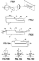
- a projector of the elliptical kind which comprises, disposed on an optical axis yy, a reflector 1 of the ellipsoidal genus receiving a light source (not shown in the figure), on the side of the opening of the reflector a cover 3 for to be placed in the vicinity of the second focus (the foremost) of the reflector, and further forward a convergent lens 4 whose focus is essentially coincident with said second focus.
- the light source is of any suitable type, for example of the filament or arc type. It may be a halogen lamp, a xenon lamp, or one or more light-emitting diodes.
- the light rays emitted by the light source are sent towards the lens or directly, or after reflection on the reflector wall. The rays then form a light beam.
- the spokes Depending on the orientation of the spokes relative to the cache, the spokes cross the cache or are intercepted by it.
- the cover 3 defines in cooperation with the reflector a light pattern having a lower cutoff profile defined by the profile of the upper edge of the cover, and the lens 4 projects this pattern to infinity by turning it over 180 degrees, to form a beam with a corresponding upper cutoff profile.
- the cache is mobile. It has at least one position called “active” optically, that is to say a position where it actually obscures a portion of the light beam, in particular for the module to emit a cut-off beam, such as a crossing-type beam (cutoff oblique) or anti-fog (horizontal cut).
- the cache can thus have one or more “active” positions, for example two, one for the traffic crossing function on the right and one for the traffic function on the left, and also a so-called “passive” function where it has a retracted position: it no longer obscures the light beam, thus allowing the module to emit light beams without cutoff, of the road beam type.
- the cache can occupy one or more intermediate active positions in which the cache is lowered and the projected cut line is raised relative to the active position.
- the displacement of the cover is achieved by any appropriate means, in particular using an electric motor controlled by a control panel or automatically. Some construction methods will be described later.
- An additional optical member is associated with the cache. This body called "bending" is located between the light source and the cache. It can be associated with the cache. Its basic function is to intercept some of the light rays that are directed against the cache and send them back over the cache so as to enhance the intensity of the light beam emitted by the projector for at least some of the positions of the cache.
- the movements of the folder and the cover are synchronized so that the cover is movable in a direction substantially perpendicular to the optical axis of the projector (and preferably substantially in a vertical plane) to provide a line clear cut and precise and also to control one or more intermediate positions.
- the folder is then advantageously "masked” or “optically inactivated” when the cover is in the extreme optically active position: the folder enters into action only when the cover is in an intermediate position, and the folder becomes inactive ( optically) when the cover is in a passive / retracted position.
- the light beam emitted by the projector comprises the light rays which are directed above the cache.
- the mask hides the folder, it means that the light rays that are reflected by the folder are intercepted by the cover, or they are not very active, that is to say that they are poorly focused relative to the lens 4.
- the folder enters into action, and the light beam is reinforced by the rays that are returned by the folder. The light intensity of the beam is thereby enhanced, together with the fact that the illuminated area is larger. In the passive position of the frame, the folder does not interfere with the light beam.
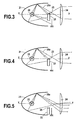
- the Figures 2 to 5 illustrate a first embodiment of the invention.
- the cache 23 is an opaque element. It has at its top a reflective surface 25 oriented parallel to the optical axis of the projector which forms the folder.
- the surface 25 is for example a film or a thin reflective coating which is deposited at the top of a block which forms the cover.
- the folder follows the path of the cutoff line, that is to say it has for the illustrated embodiment two bearings 25a, 25b separated by a connecting slope 25c.
- the cover 23 is movable perpendicular to the optical axis of the projector, and it is in the active position where it intercepts a portion of the light rays emitted by the light source 22.
- the cutoff line of the projector is centered on the axis optical yy of the projector.
- the reflecting surface 25 is not very active, that is to say that it intercepts few light rays because the reflecting surface 25 is in a part of the space where the concentration of the rays is less.
- the cover 23 is lowered into an intermediate position.
- the cache leaves the passage to a larger amount of light rays which increases the extent of the area illuminated by the projector.
- the rays such as the radius 26b which are returned by the folder, are much more numerous than in the previous position because the concentration of the rays in this region of space is maximum. These rays enhance the intensity of the light beam emitted by the projector. Thus, the larger extent of the illuminated area is accompanied by a stronger intensity light beam.
- the cover is retracted, and most of the light rays pass through the lens 24 without being intercepted or diverted by the cover and the folder which is offset with respect to the emitted beam.
- only part of the cover may have a reflective coating, particularly only one of the bearings of the cutoff line could be reflective.
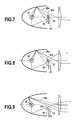
- the cover 33 is also movable perpendicular to the optical axis yy of the projector, it has a traditional structure with nevertheless a transverse drive finger 33a which is directed towards the light source and whose function will appear more clearly in the following.
- the folder 35 is formed by a blade whose reflective upper surface is oriented parallel to the optical axis of the projector.
- the blade is pivotally mounted about a transverse axis 35a located towards one of its ends. It is returned to the upper part of the headlight by any appropriate means, for example a spring, towards a stop 35b in a position where its upper surface is just a little below the level of the cutoff line 36 of the cache 33 in its active position. In this position, the finger 33a is elevated relative to the upper surface of the cache with a clearance.
- this device is as follows. In the active position of the cache 33 shown in the figure 7 , the cache is in its active position, and the brake in abutment. In this situation, the mask hides the folder, that is to say that rays such as the radius 38a are reflected by the folder, but then intercepted by the cache.
- the cache is in the intermediate position. Additional rays can cross the cover, and rays such as the previous beam 38a also, which increases the intensity of the light beam emitted by the projector.
- the finger 33a comes into contact with the folder.
- the cover is retracted downwards, and in its movement it has driven the folder with the finger 33a, so that most of the light rays emitted by the source 32 form the beam without being intercepted or diverted by the cache or the folder.
- the folder may be a zigzag folded blade, so as to follow the cut line of the cache.
- only a part of the length of the blade can be reflective so as to form the folder.
- the blade is shorter than the cut-off line and extends only along part of the length of the line. According to another variant, the blade is reflective only over part of its length.
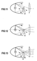
- FIGS. 10 to 13 are relative to another embodiment of the invention, with a fixed folder and a mobile cover.
- the cache 43 has a traditional structure.
- the folder 45 is the reflective upper surface of a block 45a located near the cover on the side of the light source.
- Block 45a is translucent (transparent) that is to say that it can be crossed by light rays without significantly disturbing their direction or intensity.
- the block is for example a glass block 2 to 10 mm, in particular 2 to 4 millimeters thick, and preferably 3 or 5 millimeters, whose upper surface is aluminized and is placed in such a way that the reflecting surface 45 is in the immediate vicinity of the optical axis of the projector, just a little below the cutoff line of the cache in its active position.
- the folder may be shaped so as to follow the contour of the cut line of the cover 43. Also, the folder may cover only part of the length of the cut line.
- a portion of one of the side walls of the transparent block is made opaque, or diffusing, in particular by local metallization or by frosting or by association with a blackout element.
- this operation aims, possibly, to replace a static cache, sometimes present even to make road beams, in order to delimit it clearly.
- the transparent block may have side walls parallel to each other, as shown in FIG. figure 10a This is its simplest embodiment, as shown in the figures.
- the transparent block may have a flat top edge: this is its simplest embodiment. But we can also consider that it is curved at least locally, especially depending on the length. Again, it's a parameter which can be used to influence the photometric distribution of the emitted beam.
- At least one of the front and rear faces of the translucent block is inclined relative to the vertical, (or relative to an axis perpendicular to the optical axis of the module, in the event of slight inclination of the optical axis relative to horizontally from the correction made on the module once mounted), in particular at an angle of at least 5 ° and / or at most 25 °, in particular between 10 and 20 °.
- at least one of the front and rear faces of the translucent block is curved, in particular at least partially concave.
- the lower edge of the translucent block may be thinner than its top edge.
- FIGS. 10b to 10d are cross-sectional representations of variants of the lower block.
- the figure 10b illustrates a variant of the figure 10a as regards the block 45: the front face 45b of the block is inclined towards the front (it is understood in all the text by "front” or rear "the positioning of the considered surface according to the path of the light from the source towards the output of the optical module) of an angle ⁇ of about 17 ° with respect to the vertical represented by the axis ⁇ (measured inversely in the trigonometrical direction). And the rear face 45c of the block is inclined backwards by an angle ⁇ 'also about 17 ° relative to the vertical (in the trigonometrical direction).
- the front and rear faces thus inclined so that the block has a thinner lower edge make the block play a role close to that of a lens. Concretely, this particular inclination allows to deflect some of the rays passing through the block so as to improve the quality / homogeneity of the light beam leaving the module. It has thus been observed that, by using a block with faces parallel to each other and vertical, as shown in FIG. figure 10a , in the beam of the road, it was possible to have the appearance of rays surmounting the luminous spot of principal concentration, also called "hot spot", which can appear as uncomfortable for the driver.
- the figure 10c is a variant of the figure 10b : the front face 45b of the block is more inclined forward than the rear face 45c is backward.
- an angle ⁇ of about 20 ° and an angle ⁇ 'of about 5 °. It has been found that it is the inclination of the front face 45b of the block that is most effective for deflecting the spokes in a controlled manner, and the rear face can therefore have a smaller inclination, or even be simply in a plane. vertical as at the figure 10a .
- the figure 10d is another variant of the block 45: there is always a base of the block thinner than its upper edge, but the front and rear faces 45b and 45c are curved this time: they are both concave, a curvature of 35mm. Preferably, their curvature is between 20 and 50 mm, in particular between 30 and 40 mm. It is also possible that only the front face is concave, and that the rear face remains flat, in a vertical plane, or inclined. The appropriate curvature of the face or faces of the block makes it possible to deviate the rays in a controlled manner, as explained above.
- the Figures 11 to 13 illustrate the operation of the device.
- the cache is in the active position of cutoff. It hides the folder and intercepts light rays, and rays such as the spoke 46a are returned by the folder 45 but then intercepted by the cover 43.
- the cache is lowered to an intermediate position, so that it intercepts fewer rays, and that on the other hand rays such as the previous ray 46a are returned by the folder above the cutoff line of the cache.
- the light beam emitted by the projector has a greater extent, and it is also enhanced in intensity.
- the cover is retracted, and the light beam comprises all the light rays emitted by the light source. Some rays pass through block 45a. Also the folder is in the field of the light beam, but it leaves no visible trace because of its thin thickness.
- the mask hides the folder when it is in the active position. In addition, it is moved according to two distinct modes of displacement.
- a first mode of displacement is to move the cache between its active position and an intermediate position where the folder enters into action. This is a small amplitude displacement which also requires a high precision in the positioning of the cache.
- the cache can also have several intermediate positions.
- the cover is brought into its passive position, from its active position or from its intermediate position. It is a displacement of great amplitude.
- the amplitude of the first mode of displacement is estimated at a few tenths of millimeters, in particular 0.6 millimeters, and the amplitude of the second mode of displacement at a few millimeters, in particular 6 millimeters. These distances, however, depend on the focal length of the lens.
- the movement of the cover 3 is controlled by a motor 55 and via a transmission assembly 56.
- the motor is of any suitable type, for example it is a DC motor, or a stepper motor .
- the transmission assembly is for example a screw mechanism which converts the rotation of the motor shaft into a translation.
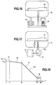
- FIG. figure 15 Another way of constructing the transmission assembly is shown in FIG. figure 15 .
- a carriage 46 guided vertically.
- the cover 53 with its cutoff line is mounted integrally on the carriage.
- the movement of the carriage is controlled by a rack 49a, 49b driven by pinions 50a, 50b themselves driven by a pinion 51 of larger diameter, the pinions being secured in rotation.
- Any appropriate means is suitable for controlling the rotation of the pinion 51, and for example a toothed wheel driven by a stepping motor.
- a spring not shown resiliently recalls the carriage in the active position of the cover which corresponds to the regulatory position of low beam.
- the cover is returned by the spring in its active position corresponding to the dipped beam.
- the first member 64 is an electromagnet whose stroke is substantially equal to the race of the cover between its active position and its passive position.
- the electromagnet allows rapid movement of the cover between these two positions.
- the second element 65 is a motor, for example a stepper motor, which drives a screw mechanism that converts the rotation of the motor shaft into a translation. This member provides low amplitude movement of the cache between an active position and an intermediate position.
- the displacement member of the cover 73 is a cam 74 driven in rotation by a motor 75.
- a spring 76 recalls the cover so that it is in contact with the cam.
- the figure 18 shows the cam path 74a in developed.
- a first segment 75 corresponds to the active position of the cache, which corresponds to the low beam.
- the following segment 76 has a low slope, it ensures a small amplitude displacement of the cache in one or more intermediate positions depending on the rotation angle of the cam.
- the next segment 77 is a transition segment to the bearing 78 which positions the cache in the passive position corresponding to high beam.
- the segment 77 has a steep slope to ensure rapid movement of the cache to the high beam position.
- the cover 83 is movable in translation, it is integrally connected to a column 82 which is guided in two rings of guide.
- the base of the column is in contact with a cam 86 of the same nature as that described above.
- the cover 93 is extended laterally by a post 92 made in one piece with the cover.
- the amount has two elongated slots 94, 95 in alignment with each other. These notches are traversed by guide pins 96, 97, and the displacement of the cover and the upright is controlled by a drive finger 98 which is in contact with the cam 99.
- the means for moving the cache are controlled by any appropriate means, automatic or manual.
- it is a radar that detects the distance with the vehicle tracked or encountered, or any other device.
- control of the present device can be achieved in coordination with a correction device which adjusts the light beam according to the attitude of the vehicle, that is to say that the same optical elements or the same control elements can be used to improve the range of the projector according to the invention, or to achieve a beam correction in relation to the attitude of the vehicle.
- the module can be used both for the regulatory lighting functions and for the AFS functions that have been mentioned at the beginning of the description and generally for any lighting or signaling function that the projector is likely to fill.
- this module can be coupled with an automatic switching device from one type of beam to another, such as for example that described in the patent application. FR2877892 .
Landscapes
- Engineering & Computer Science (AREA)
- General Engineering & Computer Science (AREA)
- Non-Portable Lighting Devices Or Systems Thereof (AREA)
- Lighting Device Outwards From Vehicle And Optical Signal (AREA)
Applications Claiming Priority (1)
| Application Number | Priority Date | Filing Date | Title |
|---|---|---|---|
| FR0704333A FR2917485B1 (fr) | 2007-06-18 | 2007-06-18 | Module optique pour dispositif d'eclairage automobile |
Publications (2)
| Publication Number | Publication Date |
|---|---|
| EP2006605A1 true EP2006605A1 (de) | 2008-12-24 |
| EP2006605B1 EP2006605B1 (de) | 2011-04-27 |
Family
ID=38754638
Family Applications (1)
| Application Number | Title | Priority Date | Filing Date |
|---|---|---|---|
| EP08157969A Not-in-force EP2006605B1 (de) | 2007-06-18 | 2008-06-10 | Fahrzeugsscheinwerfer |
Country Status (5)
| Country | Link |
|---|---|
| EP (1) | EP2006605B1 (de) |
| JP (1) | JP2009021237A (de) |
| AT (1) | ATE507435T1 (de) |
| DE (1) | DE602008006489D1 (de) |
| FR (1) | FR2917485B1 (de) |
Cited By (9)
| Publication number | Priority date | Publication date | Assignee | Title |
|---|---|---|---|---|
| EP2244007A1 (de) | 2009-04-24 | 2010-10-27 | Valeo Vision | Optische Vorrichtung für Kraftfahrzeug |
| EP2302292A1 (de) * | 2009-09-29 | 2011-03-30 | Valeo Vision | Optisches Modul mit Falzmaschine, das aus einem Diopter für transparentes Material/Luft gebildet wird |
| EP2366587A1 (de) | 2010-03-05 | 2011-09-21 | Valeo Vision | Optisches System für Kraftfahrzeug |
| FR2988807A1 (fr) * | 2012-03-30 | 2013-10-04 | Peugeot Citroen Automobiles Sa | Module optique avec cache mobile pour projecteur de vehicule |
| WO2013156520A1 (de) * | 2012-04-18 | 2013-10-24 | Osram Gmbh | Leuchtvorrichtung mit reflektor, linse und blende |
| WO2014165884A3 (de) * | 2013-04-09 | 2014-12-04 | Zizala Lichtsysteme Gmbh | Leuchteinheit mit blende mit zumindest einem lichtfenster |
| EP2228593A3 (de) * | 2009-03-12 | 2015-03-11 | Koito Manufacturing Co., Ltd. | Fahrzeugscheinwerfer |
| KR20160125693A (ko) | 2015-04-22 | 2016-11-01 | 에스엘 주식회사 | 차량용 램프 |
| WO2022183711A1 (zh) * | 2021-03-01 | 2022-09-09 | 华域视觉科技(上海)有限公司 | 车灯模组、车辆及车灯照明模组出射光形的形成方法 |
Families Citing this family (5)
| Publication number | Priority date | Publication date | Assignee | Title |
|---|---|---|---|---|
| JP2012190556A (ja) * | 2011-03-08 | 2012-10-04 | Koito Mfg Co Ltd | 車両用照明灯具 |
| KR101398225B1 (ko) | 2012-12-27 | 2014-05-23 | 현대모비스 주식회사 | 차량용 헤드 램프 |
| JP6331797B2 (ja) | 2014-07-14 | 2018-05-30 | ウシオ電機株式会社 | 車載用光源装置 |
| EP3354969B1 (de) * | 2017-01-31 | 2021-05-26 | Marelli Automotive Lighting Italy S.p.A. | Beleuchtungsvorrichtung für fahrzeuge mit rotierenden beleuchtungsmodulen |
| US10514145B1 (en) | 2018-12-20 | 2019-12-24 | Valeo North America, Inc. | Optical systems for a headlamp |
Citations (15)
| Publication number | Priority date | Publication date | Assignee | Title |
|---|---|---|---|---|
| FR2754039A1 (fr) | 1996-10-02 | 1998-04-03 | Valeo Vision | Projecteur du genre elliptique pour vehicule automobile, comportant un cache de coupure perfectionne, et procede de fabrication du cache |
| FR2762268A1 (fr) | 1997-04-22 | 1998-10-23 | Bosch Gmbh Robert | Installation de phares pour vehicules a moteur |
| EP0985577A1 (de) | 1998-09-08 | 2000-03-15 | Valeo Vision | Steuerungseinrichtung eines verstellbaren Teils eines Kfz-Scheinwerfers |
| EP1197387A1 (de) | 2000-10-12 | 2002-04-17 | Valeo Vision | Kraftfahrzeugscheinwerfer mit verstellbarer Blende |
| EP1260758A1 (de) * | 2001-05-25 | 2002-11-27 | Valeo Vision | Kfz-Scheinwerfer |
| US6550944B2 (en) | 2000-05-15 | 2003-04-22 | Koito Manufacturing Co., Ltd. | Vehicle headlamp |
| EP1422471A2 (de) | 2002-11-21 | 2004-05-26 | Valeo Vision | Elliptischer Kfz-Scheinwerfer zur Erzeugung von verschiedenen Lichtbündeln |
| EP1442472A2 (de) | 2001-11-05 | 2004-08-04 | Shimadzu Research Laboratory (Europe) Ltd. | Quadrupolionenfalle, verfahren zur verwendung derselben und ein eine solche ionenfalle enthaltender massenspekrometer |
| US20050128766A1 (en) * | 2003-10-06 | 2005-06-16 | Libor Strambersky | Variable adaptive projector system for motor vehicles |
| US20060039158A1 (en) | 2004-07-19 | 2006-02-23 | Gerhard Kurz | Vehicle headlight system with variable beam shape |
| DE102004063836A1 (de) | 2004-12-24 | 2006-03-30 | Daimlerchrysler Ag | Scheinwerfersteuerung |
| FR2877892A1 (fr) | 2004-11-18 | 2006-05-19 | Valeo Vision Sa | Procede et dispositif de commande de commutation automatique de projecteur d'eclairage |
| EP1679226A1 (de) | 2005-01-10 | 2006-07-12 | Valeo Vision | Scheinwerfer mit einem platzsparenden Stellantrieb |
| EP1746340A2 (de) | 2005-07-21 | 2007-01-24 | Valeo Vision | Optisches Modul für eine Kfz-Beleuchtungseinrichtung |
| US20070064438A1 (en) * | 2005-09-13 | 2007-03-22 | Hiroyuki Ishida | Lamp unit for a vehicle headlamp |
-
2007
- 2007-06-18 FR FR0704333A patent/FR2917485B1/fr not_active Expired - Fee Related
-
2008
- 2008-06-10 EP EP08157969A patent/EP2006605B1/de not_active Not-in-force
- 2008-06-10 AT AT08157969T patent/ATE507435T1/de not_active IP Right Cessation
- 2008-06-10 DE DE602008006489T patent/DE602008006489D1/de active Active
- 2008-06-17 JP JP2008157664A patent/JP2009021237A/ja active Pending
Patent Citations (15)
| Publication number | Priority date | Publication date | Assignee | Title |
|---|---|---|---|---|
| FR2754039A1 (fr) | 1996-10-02 | 1998-04-03 | Valeo Vision | Projecteur du genre elliptique pour vehicule automobile, comportant un cache de coupure perfectionne, et procede de fabrication du cache |
| FR2762268A1 (fr) | 1997-04-22 | 1998-10-23 | Bosch Gmbh Robert | Installation de phares pour vehicules a moteur |
| EP0985577A1 (de) | 1998-09-08 | 2000-03-15 | Valeo Vision | Steuerungseinrichtung eines verstellbaren Teils eines Kfz-Scheinwerfers |
| US6550944B2 (en) | 2000-05-15 | 2003-04-22 | Koito Manufacturing Co., Ltd. | Vehicle headlamp |
| EP1197387A1 (de) | 2000-10-12 | 2002-04-17 | Valeo Vision | Kraftfahrzeugscheinwerfer mit verstellbarer Blende |
| EP1260758A1 (de) * | 2001-05-25 | 2002-11-27 | Valeo Vision | Kfz-Scheinwerfer |
| EP1442472A2 (de) | 2001-11-05 | 2004-08-04 | Shimadzu Research Laboratory (Europe) Ltd. | Quadrupolionenfalle, verfahren zur verwendung derselben und ein eine solche ionenfalle enthaltender massenspekrometer |
| EP1422471A2 (de) | 2002-11-21 | 2004-05-26 | Valeo Vision | Elliptischer Kfz-Scheinwerfer zur Erzeugung von verschiedenen Lichtbündeln |
| US20050128766A1 (en) * | 2003-10-06 | 2005-06-16 | Libor Strambersky | Variable adaptive projector system for motor vehicles |
| US20060039158A1 (en) | 2004-07-19 | 2006-02-23 | Gerhard Kurz | Vehicle headlight system with variable beam shape |
| FR2877892A1 (fr) | 2004-11-18 | 2006-05-19 | Valeo Vision Sa | Procede et dispositif de commande de commutation automatique de projecteur d'eclairage |
| DE102004063836A1 (de) | 2004-12-24 | 2006-03-30 | Daimlerchrysler Ag | Scheinwerfersteuerung |
| EP1679226A1 (de) | 2005-01-10 | 2006-07-12 | Valeo Vision | Scheinwerfer mit einem platzsparenden Stellantrieb |
| EP1746340A2 (de) | 2005-07-21 | 2007-01-24 | Valeo Vision | Optisches Modul für eine Kfz-Beleuchtungseinrichtung |
| US20070064438A1 (en) * | 2005-09-13 | 2007-03-22 | Hiroyuki Ishida | Lamp unit for a vehicle headlamp |
Cited By (17)
| Publication number | Priority date | Publication date | Assignee | Title |
|---|---|---|---|---|
| EP2228593A3 (de) * | 2009-03-12 | 2015-03-11 | Koito Manufacturing Co., Ltd. | Fahrzeugscheinwerfer |
| DE202010018337U1 (de) | 2009-04-24 | 2015-09-14 | Valeo Vision | Optische Vorrichtung für Kraftfahrzeug |
| DE202010018335U1 (de) | 2009-04-24 | 2015-09-14 | Valeo Vision | Optische Vorrichtung für Kraftfahrzeug |
| DE202010018458U1 (de) | 2009-04-24 | 2016-10-26 | Valeo Vision | Optische Vorrichtung für Kraftfahrzeug |
| US8459849B2 (en) | 2009-04-24 | 2013-06-11 | Valeo Vision | Optical device for a motor vehicle |
| EP3045807A1 (de) | 2009-04-24 | 2016-07-20 | Valeo Vision | Optische vorrichtung für kraftfahrzeug |
| EP2244007A1 (de) | 2009-04-24 | 2010-10-27 | Valeo Vision | Optische Vorrichtung für Kraftfahrzeug |
| DE202010018336U1 (de) | 2009-04-24 | 2015-09-14 | Valeo Vision | Optische Vorrichtung für Kraftfahrzeug |
| EP2302292A1 (de) * | 2009-09-29 | 2011-03-30 | Valeo Vision | Optisches Modul mit Falzmaschine, das aus einem Diopter für transparentes Material/Luft gebildet wird |
| FR2950672A1 (fr) * | 2009-09-29 | 2011-04-01 | Valeo Vision | Module optique avec plieuse formee par un dioptre materiau transparent / air |
| EP2366587A1 (de) | 2010-03-05 | 2011-09-21 | Valeo Vision | Optisches System für Kraftfahrzeug |
| FR2988807A1 (fr) * | 2012-03-30 | 2013-10-04 | Peugeot Citroen Automobiles Sa | Module optique avec cache mobile pour projecteur de vehicule |
| WO2013156520A1 (de) * | 2012-04-18 | 2013-10-24 | Osram Gmbh | Leuchtvorrichtung mit reflektor, linse und blende |
| CN104246355A (zh) * | 2012-04-18 | 2014-12-24 | 欧司朗股份有限公司 | 具有反射器、透镜和光圈的照明设备 |
| WO2014165884A3 (de) * | 2013-04-09 | 2014-12-04 | Zizala Lichtsysteme Gmbh | Leuchteinheit mit blende mit zumindest einem lichtfenster |
| KR20160125693A (ko) | 2015-04-22 | 2016-11-01 | 에스엘 주식회사 | 차량용 램프 |
| WO2022183711A1 (zh) * | 2021-03-01 | 2022-09-09 | 华域视觉科技(上海)有限公司 | 车灯模组、车辆及车灯照明模组出射光形的形成方法 |
Also Published As
| Publication number | Publication date |
|---|---|
| FR2917485A1 (fr) | 2008-12-19 |
| ATE507435T1 (de) | 2011-05-15 |
| EP2006605B1 (de) | 2011-04-27 |
| DE602008006489D1 (de) | 2011-06-09 |
| JP2009021237A (ja) | 2009-01-29 |
| FR2917485B1 (fr) | 2009-10-09 |
Similar Documents
| Publication | Publication Date | Title |
|---|---|---|
| EP2006605B1 (de) | Fahrzeugsscheinwerfer | |
| EP1746340B1 (de) | Optisches Modul für eine Kfz-Beleuchtungseinrichtung | |
| FR2819578A1 (fr) | Phare de vehicule a eclairage reglable lateralement | |
| FR2808750A1 (fr) | Phare de vehicule, et procede de reglage lateral de son faisceau | |
| FR2787863A1 (fr) | Installation de projecteurs pour vehicules generant des faisceaux lumineux a caracteristiques differentes | |
| FR2855245A1 (fr) | Phare de vehicule a obturateur pivotant | |
| EP1684004B1 (de) | Fahrzeugscheinwerfer mit zwei Beleuchtungsverteilungen | |
| FR2824623A1 (fr) | Phare de vehicule a diagramme composite de distribution de lumiere | |
| EP1806531B1 (de) | Multifunktionales, elliptisches Scheinwerfergerät mit zusätzlichem, optischem Element | |
| WO2013034680A1 (fr) | Module optique pour projecteur de véhicule automobile | |
| FR2827945A1 (fr) | Projecteur elliptique equipe de caches a axes de pivotement transversaux pour vehicule automobile | |
| EP2068071A1 (de) | Verfahren zur automatischen Anpassung des Lichtstrahls eines optischen Moduls an die Bedingungen des Straßenverkehrs, und entsprechender Fahrzeugscheinwerfer | |
| EP1422471A2 (de) | Elliptischer Kfz-Scheinwerfer zur Erzeugung von verschiedenen Lichtbündeln | |
| EP2436968B1 (de) | Vorrichtung zur Ausstrahlung von Licht für einen Autoscheinwerfer | |
| EP2341281A1 (de) | Optisches Modul zur Erzeugung eines Code-Lichtstrahls und eines selektiven Lichtstrahls | |
| EP2006604B1 (de) | Optisches Modul für Beleuchtungseinrichtung für Fahrzeuge | |
| EP1170546A1 (de) | Elliptischer Scheinwerfer mit Strahlmodifikation durch Bewegung optischer Elemente | |
| EP0889281B1 (de) | Scheinwerfer für Kraftfahrzeuge, der zwei verschiedene Lichtverteilungmuster mit einer einzigen Lichtquelle erzeugen kann | |
| EP1870283B1 (de) | Scheinwerfereinheit mit drei Funktionen für Kraftfahrzeuge | |
| FR2898402A1 (fr) | Module optique pour projecteur automobile muni d'un element de deviation optique | |
| FR2807495A1 (fr) | Projecteur de vehicule automobile pour creer au moins un faisceau de feux de croisement | |
| EP1216882A1 (de) | Drehbarer Scheinwerfer mit einer Lampe mit zwei Lichtquellen für Fahrzeuge | |
| EP1288563A1 (de) | Beleuchtungseinrichtung zur Erzeugung eines Lichtbündels für den Verkehr bei Regenwetter | |
| FR2767903A1 (fr) | Projecteur de virage pour vehicule automobile, susceptible d'emettre des faisceaux differents | |
| EP1870634A1 (de) | Scheinwerfer mit mehreren Leuchtfunktionen, insbesondere für Kraftfahrzeuge |
Legal Events
| Date | Code | Title | Description |
|---|---|---|---|
| PUAI | Public reference made under article 153(3) epc to a published international application that has entered the european phase |
Free format text: ORIGINAL CODE: 0009012 |
|
| AK | Designated contracting states |
Kind code of ref document: A1 Designated state(s): AT BE BG CH CY CZ DE DK EE ES FI FR GB GR HR HU IE IS IT LI LT LU LV MC MT NL NO PL PT RO SE SI SK TR |
|
| AX | Request for extension of the european patent |
Extension state: AL BA MK RS |
|
| RIN1 | Information on inventor provided before grant (corrected) |
Inventor name: LETOUMELIN, REMY Inventor name: KULIG, CHRISTIAN Inventor name: BOURDIN, DAVID Inventor name: BLANDIN, JONATHAN Inventor name: ARLON, PHILIPPE Inventor name: REISS, BENOIT |
|
| 17P | Request for examination filed |
Effective date: 20090615 |
|
| 17Q | First examination report despatched |
Effective date: 20090708 |
|
| AKX | Designation fees paid |
Designated state(s): AT BE BG CH CY CZ DE DK EE ES FI FR GB GR HR HU IE IS IT LI LT LU LV MC MT NL NO PL PT RO SE SI SK TR |
|
| GRAP | Despatch of communication of intention to grant a patent |
Free format text: ORIGINAL CODE: EPIDOSNIGR1 |
|
| GRAS | Grant fee paid |
Free format text: ORIGINAL CODE: EPIDOSNIGR3 |
|
| GRAA | (expected) grant |
Free format text: ORIGINAL CODE: 0009210 |
|
| AK | Designated contracting states |
Kind code of ref document: B1 Designated state(s): AT BE BG CH CY CZ DE DK EE ES FI FR GB GR HR HU IE IS IT LI LT LU LV MC MT NL NO PL PT RO SE SI SK TR |
|
| REG | Reference to a national code |
Ref country code: GB Ref legal event code: FG4D Free format text: NOT ENGLISH |
|
| REG | Reference to a national code |
Ref country code: CH Ref legal event code: EP |
|
| REG | Reference to a national code |
Ref country code: IE Ref legal event code: FG4D Free format text: LANGUAGE OF EP DOCUMENT: FRENCH |
|
| REF | Corresponds to: |
Ref document number: 602008006489 Country of ref document: DE Date of ref document: 20110609 Kind code of ref document: P |
|
| REG | Reference to a national code |
Ref country code: DE Ref legal event code: R096 Ref document number: 602008006489 Country of ref document: DE Effective date: 20110609 |
|
| REG | Reference to a national code |
Ref country code: NL Ref legal event code: VDEP Effective date: 20110427 |
|
| LTIE | Lt: invalidation of european patent or patent extension |
Effective date: 20110427 |
|
| PG25 | Lapsed in a contracting state [announced via postgrant information from national office to epo] |
Ref country code: NO Free format text: LAPSE BECAUSE OF FAILURE TO SUBMIT A TRANSLATION OF THE DESCRIPTION OR TO PAY THE FEE WITHIN THE PRESCRIBED TIME-LIMIT Effective date: 20110727 Ref country code: LT Free format text: LAPSE BECAUSE OF FAILURE TO SUBMIT A TRANSLATION OF THE DESCRIPTION OR TO PAY THE FEE WITHIN THE PRESCRIBED TIME-LIMIT Effective date: 20110427 Ref country code: HR Free format text: LAPSE BECAUSE OF FAILURE TO SUBMIT A TRANSLATION OF THE DESCRIPTION OR TO PAY THE FEE WITHIN THE PRESCRIBED TIME-LIMIT Effective date: 20110427 Ref country code: PT Free format text: LAPSE BECAUSE OF FAILURE TO SUBMIT A TRANSLATION OF THE DESCRIPTION OR TO PAY THE FEE WITHIN THE PRESCRIBED TIME-LIMIT Effective date: 20110829 Ref country code: SE Free format text: LAPSE BECAUSE OF FAILURE TO SUBMIT A TRANSLATION OF THE DESCRIPTION OR TO PAY THE FEE WITHIN THE PRESCRIBED TIME-LIMIT Effective date: 20110427 |
|
| REG | Reference to a national code |
Ref country code: IE Ref legal event code: FD4D |
|
| PG25 | Lapsed in a contracting state [announced via postgrant information from national office to epo] |
Ref country code: AT Free format text: LAPSE BECAUSE OF FAILURE TO SUBMIT A TRANSLATION OF THE DESCRIPTION OR TO PAY THE FEE WITHIN THE PRESCRIBED TIME-LIMIT Effective date: 20110427 Ref country code: FI Free format text: LAPSE BECAUSE OF FAILURE TO SUBMIT A TRANSLATION OF THE DESCRIPTION OR TO PAY THE FEE WITHIN THE PRESCRIBED TIME-LIMIT Effective date: 20110427 Ref country code: LV Free format text: LAPSE BECAUSE OF FAILURE TO SUBMIT A TRANSLATION OF THE DESCRIPTION OR TO PAY THE FEE WITHIN THE PRESCRIBED TIME-LIMIT Effective date: 20110427 Ref country code: GR Free format text: LAPSE BECAUSE OF FAILURE TO SUBMIT A TRANSLATION OF THE DESCRIPTION OR TO PAY THE FEE WITHIN THE PRESCRIBED TIME-LIMIT Effective date: 20110728 Ref country code: CY Free format text: LAPSE BECAUSE OF FAILURE TO SUBMIT A TRANSLATION OF THE DESCRIPTION OR TO PAY THE FEE WITHIN THE PRESCRIBED TIME-LIMIT Effective date: 20110427 Ref country code: SI Free format text: LAPSE BECAUSE OF FAILURE TO SUBMIT A TRANSLATION OF THE DESCRIPTION OR TO PAY THE FEE WITHIN THE PRESCRIBED TIME-LIMIT Effective date: 20110427 Ref country code: IS Free format text: LAPSE BECAUSE OF FAILURE TO SUBMIT A TRANSLATION OF THE DESCRIPTION OR TO PAY THE FEE WITHIN THE PRESCRIBED TIME-LIMIT Effective date: 20110827 Ref country code: ES Free format text: LAPSE BECAUSE OF FAILURE TO SUBMIT A TRANSLATION OF THE DESCRIPTION OR TO PAY THE FEE WITHIN THE PRESCRIBED TIME-LIMIT Effective date: 20110807 |
|
| PG25 | Lapsed in a contracting state [announced via postgrant information from national office to epo] |
Ref country code: MT Free format text: LAPSE BECAUSE OF FAILURE TO SUBMIT A TRANSLATION OF THE DESCRIPTION OR TO PAY THE FEE WITHIN THE PRESCRIBED TIME-LIMIT Effective date: 20110427 Ref country code: NL Free format text: LAPSE BECAUSE OF FAILURE TO SUBMIT A TRANSLATION OF THE DESCRIPTION OR TO PAY THE FEE WITHIN THE PRESCRIBED TIME-LIMIT Effective date: 20110427 |
|
| BERE | Be: lapsed |
Owner name: VALEO VISION Effective date: 20110630 |
|
| PG25 | Lapsed in a contracting state [announced via postgrant information from national office to epo] |
Ref country code: IE Free format text: LAPSE BECAUSE OF FAILURE TO SUBMIT A TRANSLATION OF THE DESCRIPTION OR TO PAY THE FEE WITHIN THE PRESCRIBED TIME-LIMIT Effective date: 20110427 Ref country code: CZ Free format text: LAPSE BECAUSE OF FAILURE TO SUBMIT A TRANSLATION OF THE DESCRIPTION OR TO PAY THE FEE WITHIN THE PRESCRIBED TIME-LIMIT Effective date: 20110427 Ref country code: EE Free format text: LAPSE BECAUSE OF FAILURE TO SUBMIT A TRANSLATION OF THE DESCRIPTION OR TO PAY THE FEE WITHIN THE PRESCRIBED TIME-LIMIT Effective date: 20110427 |
|
| PG25 | Lapsed in a contracting state [announced via postgrant information from national office to epo] |
Ref country code: DK Free format text: LAPSE BECAUSE OF FAILURE TO SUBMIT A TRANSLATION OF THE DESCRIPTION OR TO PAY THE FEE WITHIN THE PRESCRIBED TIME-LIMIT Effective date: 20110427 Ref country code: PL Free format text: LAPSE BECAUSE OF FAILURE TO SUBMIT A TRANSLATION OF THE DESCRIPTION OR TO PAY THE FEE WITHIN THE PRESCRIBED TIME-LIMIT Effective date: 20110427 Ref country code: RO Free format text: LAPSE BECAUSE OF FAILURE TO SUBMIT A TRANSLATION OF THE DESCRIPTION OR TO PAY THE FEE WITHIN THE PRESCRIBED TIME-LIMIT Effective date: 20110427 Ref country code: SK Free format text: LAPSE BECAUSE OF FAILURE TO SUBMIT A TRANSLATION OF THE DESCRIPTION OR TO PAY THE FEE WITHIN THE PRESCRIBED TIME-LIMIT Effective date: 20110427 |
|
| PLBE | No opposition filed within time limit |
Free format text: ORIGINAL CODE: 0009261 |
|
| STAA | Information on the status of an ep patent application or granted ep patent |
Free format text: STATUS: NO OPPOSITION FILED WITHIN TIME LIMIT |
|
| PG25 | Lapsed in a contracting state [announced via postgrant information from national office to epo] |
Ref country code: BE Free format text: LAPSE BECAUSE OF NON-PAYMENT OF DUE FEES Effective date: 20110630 |
|
| 26N | No opposition filed |
Effective date: 20120130 |
|
| REG | Reference to a national code |
Ref country code: DE Ref legal event code: R097 Ref document number: 602008006489 Country of ref document: DE Effective date: 20120130 |
|
| PG25 | Lapsed in a contracting state [announced via postgrant information from national office to epo] |
Ref country code: IT Free format text: LAPSE BECAUSE OF FAILURE TO SUBMIT A TRANSLATION OF THE DESCRIPTION OR TO PAY THE FEE WITHIN THE PRESCRIBED TIME-LIMIT Effective date: 20110427 |
|
| REG | Reference to a national code |
Ref country code: CH Ref legal event code: PL |
|
| REG | Reference to a national code |
Ref country code: CH Ref legal event code: PL |
|
| GBPC | Gb: european patent ceased through non-payment of renewal fee |
Effective date: 20120610 |
|
| PG25 | Lapsed in a contracting state [announced via postgrant information from national office to epo] |
Ref country code: LI Free format text: LAPSE BECAUSE OF NON-PAYMENT OF DUE FEES Effective date: 20120630 Ref country code: GB Free format text: LAPSE BECAUSE OF NON-PAYMENT OF DUE FEES Effective date: 20120610 Ref country code: MC Free format text: LAPSE BECAUSE OF NON-PAYMENT OF DUE FEES Effective date: 20110630 Ref country code: CH Free format text: LAPSE BECAUSE OF NON-PAYMENT OF DUE FEES Effective date: 20120630 |
|
| PG25 | Lapsed in a contracting state [announced via postgrant information from national office to epo] |
Ref country code: LU Free format text: LAPSE BECAUSE OF NON-PAYMENT OF DUE FEES Effective date: 20110610 |
|
| PG25 | Lapsed in a contracting state [announced via postgrant information from national office to epo] |
Ref country code: BG Free format text: LAPSE BECAUSE OF FAILURE TO SUBMIT A TRANSLATION OF THE DESCRIPTION OR TO PAY THE FEE WITHIN THE PRESCRIBED TIME-LIMIT Effective date: 20110727 |
|
| PG25 | Lapsed in a contracting state [announced via postgrant information from national office to epo] |
Ref country code: TR Free format text: LAPSE BECAUSE OF FAILURE TO SUBMIT A TRANSLATION OF THE DESCRIPTION OR TO PAY THE FEE WITHIN THE PRESCRIBED TIME-LIMIT Effective date: 20110427 |
|
| PG25 | Lapsed in a contracting state [announced via postgrant information from national office to epo] |
Ref country code: HU Free format text: LAPSE BECAUSE OF FAILURE TO SUBMIT A TRANSLATION OF THE DESCRIPTION OR TO PAY THE FEE WITHIN THE PRESCRIBED TIME-LIMIT Effective date: 20110427 |
|
| REG | Reference to a national code |
Ref country code: FR Ref legal event code: PLFP Year of fee payment: 9 |
|
| REG | Reference to a national code |
Ref country code: FR Ref legal event code: PLFP Year of fee payment: 10 |
|
| REG | Reference to a national code |
Ref country code: FR Ref legal event code: PLFP Year of fee payment: 11 |
|
| PGFP | Annual fee paid to national office [announced via postgrant information from national office to epo] |
Ref country code: DE Payment date: 20180607 Year of fee payment: 11 |
|
| PGFP | Annual fee paid to national office [announced via postgrant information from national office to epo] |
Ref country code: FR Payment date: 20180627 Year of fee payment: 11 |
|
| REG | Reference to a national code |
Ref country code: DE Ref legal event code: R119 Ref document number: 602008006489 Country of ref document: DE |
|
| PG25 | Lapsed in a contracting state [announced via postgrant information from national office to epo] |
Ref country code: DE Free format text: LAPSE BECAUSE OF NON-PAYMENT OF DUE FEES Effective date: 20200101 |
|
| PG25 | Lapsed in a contracting state [announced via postgrant information from national office to epo] |
Ref country code: FR Free format text: LAPSE BECAUSE OF NON-PAYMENT OF DUE FEES Effective date: 20190630 |