EP2006561A1 - Ensemble de roulement - Google Patents
Ensemble de roulement Download PDFInfo
- Publication number
- EP2006561A1 EP2006561A1 EP08011377A EP08011377A EP2006561A1 EP 2006561 A1 EP2006561 A1 EP 2006561A1 EP 08011377 A EP08011377 A EP 08011377A EP 08011377 A EP08011377 A EP 08011377A EP 2006561 A1 EP2006561 A1 EP 2006561A1
- Authority
- EP
- European Patent Office
- Prior art keywords
- retaining
- retainer plate
- diameter
- larger
- outer ring
- Prior art date
- Legal status (The legal status is an assumption and is not a legal conclusion. Google has not performed a legal analysis and makes no representation as to the accuracy of the status listed.)
- Granted
Links
Images


Classifications
-
- F—MECHANICAL ENGINEERING; LIGHTING; HEATING; WEAPONS; BLASTING
- F16—ENGINEERING ELEMENTS AND UNITS; GENERAL MEASURES FOR PRODUCING AND MAINTAINING EFFECTIVE FUNCTIONING OF MACHINES OR INSTALLATIONS; THERMAL INSULATION IN GENERAL
- F16C—SHAFTS; FLEXIBLE SHAFTS; ELEMENTS OR CRANKSHAFT MECHANISMS; ROTARY BODIES OTHER THAN GEARING ELEMENTS; BEARINGS
- F16C33/00—Parts of bearings; Special methods for making bearings or parts thereof
- F16C33/30—Parts of ball or roller bearings
- F16C33/58—Raceways; Race rings
- F16C33/583—Details of specific parts of races
- F16C33/586—Details of specific parts of races outside the space between the races, e.g. end faces or bore of inner ring
-
- F—MECHANICAL ENGINEERING; LIGHTING; HEATING; WEAPONS; BLASTING
- F16—ENGINEERING ELEMENTS AND UNITS; GENERAL MEASURES FOR PRODUCING AND MAINTAINING EFFECTIVE FUNCTIONING OF MACHINES OR INSTALLATIONS; THERMAL INSULATION IN GENERAL
- F16C—SHAFTS; FLEXIBLE SHAFTS; ELEMENTS OR CRANKSHAFT MECHANISMS; ROTARY BODIES OTHER THAN GEARING ELEMENTS; BEARINGS
- F16C35/00—Rigid support of bearing units; Housings, e.g. caps, covers
- F16C35/04—Rigid support of bearing units; Housings, e.g. caps, covers in the case of ball or roller bearings
- F16C35/06—Mounting or dismounting of ball or roller bearings; Fixing them onto shaft or in housing
- F16C35/067—Fixing them in a housing
-
- F—MECHANICAL ENGINEERING; LIGHTING; HEATING; WEAPONS; BLASTING
- F16—ENGINEERING ELEMENTS AND UNITS; GENERAL MEASURES FOR PRODUCING AND MAINTAINING EFFECTIVE FUNCTIONING OF MACHINES OR INSTALLATIONS; THERMAL INSULATION IN GENERAL
- F16C—SHAFTS; FLEXIBLE SHAFTS; ELEMENTS OR CRANKSHAFT MECHANISMS; ROTARY BODIES OTHER THAN GEARING ELEMENTS; BEARINGS
- F16C19/00—Bearings with rolling contact, for exclusively rotary movement
- F16C19/02—Bearings with rolling contact, for exclusively rotary movement with bearing balls essentially of the same size in one or more circular rows
- F16C19/04—Bearings with rolling contact, for exclusively rotary movement with bearing balls essentially of the same size in one or more circular rows for radial load mainly
- F16C19/06—Bearings with rolling contact, for exclusively rotary movement with bearing balls essentially of the same size in one or more circular rows for radial load mainly with a single row or balls
-
- F—MECHANICAL ENGINEERING; LIGHTING; HEATING; WEAPONS; BLASTING
- F16—ENGINEERING ELEMENTS AND UNITS; GENERAL MEASURES FOR PRODUCING AND MAINTAINING EFFECTIVE FUNCTIONING OF MACHINES OR INSTALLATIONS; THERMAL INSULATION IN GENERAL
- F16C—SHAFTS; FLEXIBLE SHAFTS; ELEMENTS OR CRANKSHAFT MECHANISMS; ROTARY BODIES OTHER THAN GEARING ELEMENTS; BEARINGS
- F16C2226/00—Joining parts; Fastening; Assembling or mounting parts
- F16C2226/50—Positive connections
- F16C2226/60—Positive connections with threaded parts, e.g. bolt and nut connections
-
- F—MECHANICAL ENGINEERING; LIGHTING; HEATING; WEAPONS; BLASTING
- F16—ENGINEERING ELEMENTS AND UNITS; GENERAL MEASURES FOR PRODUCING AND MAINTAINING EFFECTIVE FUNCTIONING OF MACHINES OR INSTALLATIONS; THERMAL INSULATION IN GENERAL
- F16C—SHAFTS; FLEXIBLE SHAFTS; ELEMENTS OR CRANKSHAFT MECHANISMS; ROTARY BODIES OTHER THAN GEARING ELEMENTS; BEARINGS
- F16C2226/00—Joining parts; Fastening; Assembling or mounting parts
- F16C2226/50—Positive connections
- F16C2226/70—Positive connections with complementary interlocking parts
- F16C2226/74—Positive connections with complementary interlocking parts with snap-fit, e.g. by clips
-
- F—MECHANICAL ENGINEERING; LIGHTING; HEATING; WEAPONS; BLASTING
- F16—ENGINEERING ELEMENTS AND UNITS; GENERAL MEASURES FOR PRODUCING AND MAINTAINING EFFECTIVE FUNCTIONING OF MACHINES OR INSTALLATIONS; THERMAL INSULATION IN GENERAL
- F16C—SHAFTS; FLEXIBLE SHAFTS; ELEMENTS OR CRANKSHAFT MECHANISMS; ROTARY BODIES OTHER THAN GEARING ELEMENTS; BEARINGS
- F16C2361/00—Apparatus or articles in engineering in general
- F16C2361/61—Toothed gear systems, e.g. support of pinion shafts
-
- Y—GENERAL TAGGING OF NEW TECHNOLOGICAL DEVELOPMENTS; GENERAL TAGGING OF CROSS-SECTIONAL TECHNOLOGIES SPANNING OVER SEVERAL SECTIONS OF THE IPC; TECHNICAL SUBJECTS COVERED BY FORMER USPC CROSS-REFERENCE ART COLLECTIONS [XRACs] AND DIGESTS
- Y10—TECHNICAL SUBJECTS COVERED BY FORMER USPC
- Y10S—TECHNICAL SUBJECTS COVERED BY FORMER USPC CROSS-REFERENCE ART COLLECTIONS [XRACs] AND DIGESTS
- Y10S384/00—Bearings
- Y10S384/90—Cooling or heating
- Y10S384/903—Retaining ring
Definitions
- This invention relates to an improved rolling bearing unit which is a part of a rotation support unit (for example, a manual transmission or an automatic transmission of an automobile transmission) for supporting an end portion of a rotation shaft on an inner surface of a housing containing component parts of the automobile transmission.
- a rotation support unit for example, a manual transmission or an automatic transmission of an automobile transmission
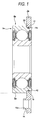
- an end portion of a rotation shaft 1 such as a counter shaft of an automobile transmission is rotatably supported on an inner surface of a housing 2 accommodating components such as the rotation shaft 1, a gear, etc., through a rolling bearing 3 such as a ball bearing.
- a rolling bearing 3 such as a ball bearing.
- an annular or circular holding recess 4 is formed in the inner surface of the housing 2, and an outer ring 5 of the rolling bearing 3 is fitted in the holding recess 4 to be inwardly fixed thereto in an interference manner.
- the end portion of the rotation shaft 1 is inwardly fitted in the interference manner or the like in an inner ring 6 of the rolling bearing 3 against radial movement.
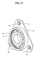
- the outer ring 5 is held against one axial end face of the holding recess 4 by a retainer plate 7.
- the left side in Figs. 1 , 3 , 4 , 30 and etc. is defined as one axial end, while the right side is defined as the other axial end.
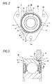
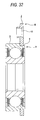
- the rolling bearing 3 and the retainer plate 7 are coupled together to form a bearing unit 8 as shown in Figs. 31 and 32 so that this bearing unit 8 can be easily mounted in the holding recess 4.
- the retainer plate 7 is fitted on a smaller-diameter step portion 9 formed on an outer circumferential surface of the other axial end portion of the outer ring 5 of the rolling bearing 3, and can rotate relative to this outer ring 5.
- the rolling bearing unit 8 is mounted within the housing 2 with the outer ring 5 fitted in an interference manner in the holding recess 4 and also with one side face of the retainer plate 7 held against an inner surface of the housing 2. Then, by rotating the retainer plate 7 relative to the outer ring 5, through holes 10 formed through an outer circumferential portion of the retainer plate 7 are brought into alignment respectively with screw holes (not shown) formed in the inner surface of the housing 2. Then, screws are passed through the respective through holes 10, and are threaded into the respective screw holes, and are further tightened.
- screw holes are formed in the outer circumferential portion of the retainer plate 7, and screws are passed from the exterior through respective through holes formed in the housing 2, and are threaded into the respective screw holes, and are further tightened.
- heads of the screws are prevented from projecting into the housing from the retainer plate, and a space within the housing can be efficiently utilized.
- the outer ring 5 is fixedly supported in the holding recess 4 without rattling and also without falling-off from this holding recess 4.
- the retainer plate 7 is rotatably connected to the outer ring 5, and is prevented from separation from the outer ring 5.
- the retainer plate 7 is thus rotatable relative to the outer ring 5 so that the through holes 10 and the screw holes can be brought into alignment with each other after the outer ring 5 is fitted in the holding recess 4 in an interference manner or the like against radial movement.
- the retainer plate 7 is thus not separated from the outer ring 5 so that the rolling bearing 3 and the retainer plate 7 can be handled as a single unit so as to facilitate the management of the parts, an assembling operation, etc.
- the outer ring 5 and the retainer plate 7 are connected together so as to rotate relative to each other but can not be separated from each other.
- a plurality of projections formed on an inner circumferential edge of the retainer plate are engaged in a circumferential recess formed in an outer circumferential surface of the smaller-diameter step portion.
- the side face of the retainer plate is held by a leaf spring held on an outer circumferential surface of the smaller-diameter step portion.
- an inner circumferential edge of the retainer plate is plastically deformed, and is engaged in a circumferential recess formed in an outer circumferential surface of the smaller-diameter step portion.
- This invention has been made in view of the above circumstances, and an object of the invention is to provide a rotation support unit and a rolling bearing unit for a rotation support unit, in which a structure of combination of an outer ring of a rolling bearing and a retainer plate for retaining the outer ring in a holding recess can be easily obtained at a low cost.
- a rolling bearing unit for rotatably supporting a rotation shaft on a housing, including:
- a distance between a bottom surface of the recess portion of the retainer plate and the inner circumferential surface of the retainer plate is defined as a depth, in the bottom surface of the recess portion of the retainer plate, the depth at one circumferential end portion is smaller than that at the other circumferential end portion.
- the fitting holes has three or more recess portions, and also the retaining ring has three or more larger-diameter retaining portions, and the recess portions and the larger-diameter retaining portions are equal in number to each other, and are provided at the same pitch.
- the amount of radially-outwardly projection of the larger-diameter retaining portion formed at a circumferentially-intermediate portion of the retaining ring remote from an interrupted portion thereof is smaller than the amount of projection of the other larger-diameter retaining portions disposed near to the interrupted portion.
- the retaining ring may have a bullet-shaped cross-section.
- a face of the retaining ring at the one axial end side is a flat surface disposed perpendicular to the center axis of the retaining ring, and the other axial end side face of the retaining ring is formed into an inclined surface which is sharpened at the one axial end side, that is, gradually decreasing in outer diameter toward a distal end thereof
- the cross-sectional shape of the retaining ring may be such that the outer circumferential surface of the retaining ring has a convex arc-shaped cross-section, and the retaining ring has a substantially triangular cross-section.
- the structure of combination of the outer ring of the rolling bearing and the retainer plate for retaining the outer ring in the holding recess can be easily obtained within low cost.
- the retaining ring for connecting the outer ring and the retainer plate together can be easily formed by bending a resilient metal wire or by injection molding a synthetic resin.
- the retaining recessed groove for retaining the retaining ring can be easily formed in the outer circumferential surface of the smaller-diameter step portion of the outer ring by a simple lathe turning operation.
- the recess portions and the retaining projections can be easily formed at the inner circumferential surface of the fitting hole of the retainer plate by press working. Therefore, the above structure can be easily obtained at the low cost as described above.
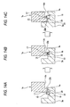
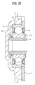
- Figs. 1 to 12 shows a first embodiment of the present invention.
- the rolling bearing unit 8a of this embodiment includes a retainer plate 7a which is connected to an outer ring 5a of a rolling bearing 3a through a retaining ring 11 in such a manner that the retainer plate 7a can rotate relative to the outer ring 5a but can not be separated therefrom.
- This rolling bearing unit 8a is used to rotatably support an end portion of the rotation shaft 1 on the inner surface of the housing 2 of an automatic transmission as shown in Fig. 30 .
- the rolling bearing unit 8a is mounted between the housing 2 and the rotation shaft 1 in the same manner as described above for the conventional structure of Fig.
- a smaller-diameter step portion 9a is formed on other axial side outer circumferential surface of the outer ring 5a at a portion which projects from the retaining recess 4 in a state that the outer ring 5a is inwardly fitted to the retaining recess 4 of the housing 2 ( Fig. 30 ).
- the retainer plate 7a is outwardly fitted and supported on the smaller-diameter step portion 9a in such a manner that the retainer plate 7a can be rotated relative to the smaller-diameter step portion 9a and is prevented from falling off the smaller-diameter step portion 9a.
- the retainer plate 7a is formed by applying press working such as stamping, pressing, burring, etc., to a sheet of metal such as stainless steel.
- the retainer plate 7a includes a fitting hole 12, to which the smaller-diameter step portion 9a is outwardly fitted, formed through a central portion thereof, and three through holes or screw holes 10a formed through an outer circumferential portion thereof and disposed at equal intervals in a circumferential direction.
- cylindrical portions 14 are formed on portions surrounding the through holes or screw holes 10a. These cylindrical portion 14 are fitted to a positioning holes which are formed on opening portion of the screw holes or through holes formed in the inner surface of the housing 2 and which is larger in diameter than the screw holes or the through holes, when the retainer plate 7a is abutted to the inner surface of the housing 2.
- the position of the retainer plate 7a in the rotational direction can be set.
- each cylindrical portion 14 also secures the axial dimension of this screw hole 10a and therefore serves to secure the strength and rigidity of the screw portion.
- the provision of the cylindrical portions 14 may be omitted.
- the retaining ring 11 outwardly fitted to the smaller-diameter step portion 9a is engaged with retaining projections 15 which is formed on plurality of portions (in the illustrated embodiment, three in circumferential direction with equal intervals) on inner circumferential surface of the fitting hole 12 formed on a center of the retainer plate 7a. According to this engagement, the retainer plate 7a is prevented from falling off the smaller-diameter step portion 9a.
- the retaining ring 11 which is formed by bending a resilient metal wire or by injection molding a high-functional synthetic resin, has an interrupted ring-shape as a whole as shown in Figs. 5 and 6 , and can be elastically expanded and contracted in diameter.
- This retaining ring 11 includes a smaller-diameter portion 16 serving as a base portion, and a plurality of (in the illustrated embodiment, three in the circumferential direction with equal intervals) larger-diameter retaining portions 17 formed respectively at those portions of the smaller-diameter portion 16 disposed at substantially equal intervals in the circumferential direction and bent or bulged radially outwardly.
- Each larger-diameter retaining portions 17 has a partially arc-shape larger in curvature than the smaller-diameter portion 16, and projects radially outwardly from the outer periphery of the smaller-diameter portion 16.
- a retaining recessed groove 18 of a channel-shaped cross-section for retaining the retaining ring 11 is formed in an axially-intermediate portion of the outer circumferential surface of the smaller-diameter step portion 9a over the entire periphery thereof as shown in Figs. 1 , 3 , 4 and 10 to 12 .
- the retaining recessed groove 18 has such a size (volume) that the smaller-diameter portion 16 of the retaining ring 11, when received in the retaining recessed groove 18, will not project radially outwardly from the outer circumferential surface of the smaller-diameter step portion 9a.
- a depth d 18 and a width w 18 of the retaining recessed groove 18 are equal to or slightly larger than a height h 11 and a width w 11 of a cross-section of the retaining ring 11, respectively (d 18 ⁇ h 11 , w 18 ⁇ w 11 ) (see Fig. 4 ).
- a height h 17 (see Fig. 11 ) of each larger-diameter retaining portion 17 in its free condition is larger than the depth d 18 of the retaining recessed groove 11 (h 17 > d 18 ).
- the fitting hole 12 formed through the central portion of the retainer plate 7a is circular except a plurality of larger-diameter portions 19 (described later), and has such an inner diameter that the inner circumferential surface of the fitting hole 12 is loosely fitted on the smaller-diameter step portion 9a of the outer ring 5a while having a clearance therebetween.
- the larger-diameter portions (recess portions) 19 are formed respectively in a plurality of (three in the illustrated embodiment) portions of the inner circumferential surface of the fitting hole 12 disposed at equal intervals in the circumferential direction, and are recessed radially outwardly from the inner periphery of the fitting hole 12.
- the retaining projection 15 is formed at one axial end of the larger-diameter portion 19 as shown in Figs: 4 and 9 .
- a larger-diameter outer circumferential surface is formed on the one axial end portion of the outer periphery of the outer ring 5a, while the smaller-diameter step portion 9a is formed on the other axial end portion of the outer periphery of the outer ring 5a, and a step surface 20 is formed between the larger-diameter outer circumferential surface and the smaller-diameter step portion 9a.
- each retaining projection 15 of the retainer plate 7a is disposed close to the step surface 20 formed at the one axial end side relative to the smaller-diameter step portion 9a.
- An inner circumferential surface of each retaining projection 15 is an inclined surface of a conical concave shape of which inner diameter gradually increases toward the one axial end portion of the larger-diameter portion 19 (toward the step surface 20).
- a distal end edge of each retaining projection 15 is disposed on or slightly radially outwardly of a circle on which the inner periphery of a main portion of the fitting hole 12 lies.
- the retainer plate 7a has a substantially triangular shape (an inequilateral hexagon) as obtained by cutting three circumferentially-spaced portions from a disk.
- the through holes or screw holes 10a are formed respectively through three circumferentially-spaced portions having the largest outer diameter. Therefore, the outer diameter of these largest-diameter portions having the respective through holes or screw holes 10a is much larger than an outer diameter of intervening portions 21 each lying between the adjacent largest-diameter portions.
- the larger-diameter portions 19 are thus formed respectively at the above-mentioned portions other than the vicinities of the through holes or screw holes 10a to which a large stress is applied upon tightening of a bolt and small-width portions on which a large stress is liable to act.
- the larger-diameter portions 19 should be formed respectively at the above-mentioned portions.
- the larger-diameter portions 19 may be formed respectively at those portions which are disposed in phase respectively with the through holes or screw holes 10a in the circumferential direction.
- the retaining ring 11 is attached to the retaining recessed groove 18 formed in the outer circumferential surface of the smaller-diameter step portion 9a of the outer ring 5a.
- the smaller-diameter portion 16 of the retaining ring 11 is fitted into the retaining recessed groove 18 while elastically expanding the inner diameter of the retaining ring 11. Because of its own elasticity, the thus fitted retaining ring 11 is retained in the retaining recessed groove 18 against disengagement..
- the plurality of larger-diameter portions 17 formed at the retaining ring 11 project radially outwardly from the outer circumferential surface of the smaller-diameter step portion 9a as shown in Fig. 10 .
- the retaining ring 11 is thus attached to the retaining recessed groove 18, and then the retainer plate 7a is outwardly fitted on the smaller-diameter step portion 9a.
- the retaining projections 15 are opposed respectively to the larger-diameter portions 19 (that is, phases of the retaining projections 15 and the larger-diameter portions 19 are matched in the circumferential direction), and in this condition the retainer plate 7a is outwardly fitted onto the smaller-diameter step portion 9a as indicated by an arrow in Fig. 11 .
- the inner circumferential surfaces of the retaining projections 15 formed on the inner circumferential surface of the fitting hole 12 of the retainer plate 7a are brought into engagement with the respective larger-diameter retaining portions, and compress these larger-diameter retaining portions 17, so that the retaining projections 15 are allowed to pass the respective larger-diameter retaining portions 17.
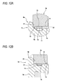
- the larger-diameter retaining portions 17 are elastically restored, and are opposed respectively to the retaining projections 15 in the axial direction as shown in Figs. 3 , 4 and 12A .
- each retaining projection 15 of the retainer plate 7a is disposed between the step surface 20 of the outer ring 5a and the corresponding larger-diameter retaining portion 17 of the retaining ring 11.
- the retaining ring 11 is prevented from falling off the outer ring 5a since the smaller-diameter portion 16 is engaged in the retaining recessed groove 18. Therefore, the retainer plate 7a is also prevented from being separated from the outer ring 5a.
- the inner circumferential surface of the fitting hole: 12 except the larger-diameter portions L9 is closely fitted on the smaller-diameter step portion 9a as shown in Fig. 12B . Therefore, the retainer plate 7a and the outer ring 5a are coupled together in substantially concentric with each other.
- the rolling bearing unit 8a of this embodiment for a rotation support unit which includes the above constituent members assembled together as described above, is mounted between the rotation shaft 1 and the housing 2 as shown in Fig. 30 as well as the above-mentioned conventional structure.
- the assembling procedure, etc. are similar to those of the above conventional structure.
- the through holes or screw holes 10a are aligned with the respective screw holes or through holes 10a.
- the retainer plate 7a is brought into abutting engagement with the inner surface of the housing 2 by tightening the screws or by pushing the outer ring 5a into the retaining recess 4 after the above aligning operation is effected.
- the structure of combination of the outer ring 5a of the rolling bearing 3a and the retainer plate 7a for retaining the outer ring 5a in the holding recess 4 can be easily obtained at a low cost.
- the retaining ring 11 for connecting the outer ring 5 and the retainer plate 7a together can be easily obtained by bending a resilient wire of metal such as spring steel of stainless steel, carbon steel and phosphor bronze or by injection molding a high-functional synthetic resin having superior elasticity, an oil resistance and a thermal resistance.
- the retaining recessed groove 18 for retaining the retaining ring 11 can be easily formed in the outer circumferential surface of the smaller-diameter step portion 9a of the outer ring 5a by a simple lathe turning operation.
- the larger-diameter portions 19 and the retaining projections 15 can be easily formed at the inner circumferential surface of the fitting hole 12 of the retainer plate 7a by press working such as stamping, pressing, etc.
- either of the outer ring 5a and the retainer plate 7a does not require any plastic working such as caulking (fixing using plastic deformation), and therefore part of them does not need to be kept relatively soft, and can secure necessary hardness by quench hardening.
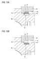
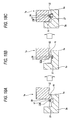
- Fig. 13 shows a second embodiment of the invention.
- an inner diameter of a fitting hole 12a formed through a central portion of a retainer plate 7b is sufficiently larger than an outer diameter of a smaller-diameter step portion 9a (on which the retainer plate 7b to be fitted and supported) formed on an outer circumferential surface of an end portion of an outer ring 5a (that is, larger than a circle circumscribing larger-diameter retaining portions 17 of a retaining ring 11).
- the retaining projection 15a is formed on one axial end of the inner circumferential surface of the fitting hole 12a over the entire periphery thereof, and projects radially inwardly from the inner circumferential surface of the fitting hole 12a.
- the basic shape of the retaining projection 15a is similar to that of the retaining projections 15 (see Figs. 3 , 4 , 9 , 11 and 12 ) of the above first embodiment.
- the fitting hole 12a of the retainer plate 7b and .the retaining projection 15a are formed into the above-mentioned shapes, respectively.
- a smaller-diameter portion 16 of the retaining ring 11 is housed into a retaining recessed groove 18 formed in an axially-intermediate portion of the outer circumferential surface of the smaller-diameter step portion 9a as shown in Fig. 13B .
- the fitting hole 12a is outwardly fitted on the smaller-diameter step portion 9a while passing the retaining projection 15a past the larger-diameter retaining portions 17 as described above for the first embodiment with reference to Fig. 11 .
- the retaining projection 15a is disposed between a step surface 20 and the larger-diameter retaining portions 17, and the retaining projection 15a is engaged with the larger-diameter retaining portions 17 as shown in Fig. 13A , thereby preventing the retainer plate 7b from falling off the smaller-diameter step portion 9a.
- a distal end edge of the retaining projection 15a is in contact with or is closely opposed to the outer circumferential surface of the smaller-diameter step portion 9a.
- magnitude of a radial load applied between the retainer plate 7b and the outer ring 5a is such a small value that it is substantially equal to the weight of the retainer plate 7b or a rolling bearing unit including the outer ring 5a.
- the other portions are similar in structure and operation to those of the above first embodiment, and therefore the description and showing of such similar portions will be omitted.
- Fig. 14 shows a third embodiment of the invention.
- An inner circumferential surface of a retaining projection 15b formed on an inner circumferential surface of a fitting hole 12b formed through a central portion of a retainer plate 7c is formed by an inclined surface 22 and a concave cylindrical surface 23.
- the inclined surface 22 is formed at one axial end portion of the inner circumferential surface of the retaining projection 15b, and has a conical concave shape of which inner diameter increases toward the one axial end.
- the inclined surface 22 is disposed on one axial end portion of this smaller-diameter step portion 9a.
- the concave cylindrical surface 23 is formed on the other axial end portion of the inner circumferential surface of the retaining projection 15b, and the inner diameter thereof is constant along with the axial direction.
- the concave cylindrical surface 23 is disposed on substantially an axially-central portion of this smaller-diameter step portion 9a.
- the retaining projection 15b formed on the inner circumferential surface of the fitting hole 12b of the retainer plate 7c is formed into the above-mentioned shape.
- the fitting hole 12b is outwardly fitted on the smaller-diameter step portion 9a in the sequence from Fig. 14A, to Fig. 14C as described above for the second embodiment.
- the retaining projection 15 is pushed onto the smaller-diameter step portion 9a toward the one axial end thereof while the larger-diameter retaining portions 17 of a retaining ring 11 are elastically compressed by this retaining projection 15b.
- the retaining projection 15b is disposed between a step surface 20 and the larger-diameter retaining portions 17 as shown in Fig. 14C , and the retaining projection 15b is engaged with the larger-diameter retaining portions 17, thereby preventing the retainer plate 7c from falling off the smaller-diameter step portion 9a.
- the concave cylindrical surface 23 opposes to an axially one end side cylindrical surface of the smaller-diameter step portion which is located axially one end side relative to the retaining recessed groove 18 formed on the axially intervening portion of the smaller-diameter step portion 9a.
- the concave cylindrical surface 23 abut with or closely opposes to the one axial end portion of the smaller-diameter step portion 9a.
- An area of contact between the concave cylindrical surface 23 and the one axial end portion of the smaller-diameter step portion 9a is increased to a certain degree.
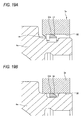
- Fig. 15 shows a fourth embodiment of the invention.
- a retaining projection 15a and a support projection 24 are formed respectively on axially-opposite end portions of an inner circumferential surface of a fitting hole 12c formed through a central portion of a retainer plate 7d, and are spaced from each other in the axial direction.
- the retaining projection 15a is formed on one axial end portion of the inner circumferential surface of the fitting hole 12c over the entire periphery thereof, and the support projection 24 is formed on the other axial end portion of this inner circumferential surface over the entire periphery thereof, and an outer-diameter recessed retaining recessed groove 25 is formed between the two projections 15a and 24 over the entire periphery thereof
- the fitting hole 12c is outwardly fitted on a smaller-diameter step portion 9a formed on an outer circumferential surface of an end portion of an outer ring 5a
- the retaining projection 15a is disposed on one axial end side of the smaller-diameter step portion 9a.
- the support projection 24 is disposed opposite side of the retaining projection 15a while interposing the outer-diameter retaining recessed groove 25 therebetween.
- An inner circumferential surface of the retaining projection 15a is defined by an inclined surface 22a gradually increasing in inner diameter away from the outer-diameter retaining recessed groove 25.
- an inner circumferential surface of the support projection 24 is defined by a concave cylindrical surface 26 of which inner diameter is constant along with the axial direction.
- the support projection 24 when the fitting hole 12c is outwardly fitted on the smaller-diameter step portion 9a formed on the outer circumferential surface of the end portion of the outer ring 5a of a rolling bearing unit, larger-diameter retaining portions 17 of a retaining ring 11 are engaged with the retaining projection 15a, thereby preventing the retainer plate 7d from falling off the smaller-diameter step portion 9a. Also, the inner circumferential surface' of the support projection 24 is opposed to the other axial end portion of the smaller-diameter step portion 9a.
- this support projection 24 is the concave cylindrical surface and the outer circumferential surface of the other axial end portion of the smaller-diameter step portion 9a is a concave cylindrical surface, these two cylindrical surfaces differ only slightly in radius curvature from each other, and therefore contact each other with a large area.
- damage is less liable to develop on the connected portion between the retainer plate 7d and the outer ring 5a.
- the other portions are similar in structure and operation to those of the above second embodiment shown in Fig. 13 , and therefore the description and showing of such similar portions will be omitted.
- Fig. 16 shows a fifth embodiment of the invention.
- This embodiment has a structure as obtained by a combination of the above fourth and third embodiments. Namely, in this embodiment, an inner circumferential surface of a retaining projection 15b formed on an inner circumferential surface of a fitting hole 12d formed through a central portion of a retainer plate 7e is formed by an inclined surface 22 and a concave cylindrical surface 23. Also, a concave cylindrical surface 26 which is equal in diameter to the concave cylindrical surface 23 and is concentric therewith is formed on a potion opposite to the retaining projection 15b while interposing the outer-diameter retaining recessed groove 25 therebetween. Therefore, in the structure of this embodiment, when the assembling operation is completed as shown in Fig.
- the two concave cylindrical surfaces 23 and 26 are in contact with or are closely opposed to outer circumferential surfaces of opposite end portions of a smaller-diameter step portion 9a formed on an outer circumferential surface of an end portion of an outer ring 5a which constitutes the rolling bearing unit. Areas of contact of the two concave cylindrical surfaces 23 and 26 with the axially one end of the smaller-diameter step portion 9a are sufficiently large, and therefore the connected portion between the retainer plate 7e and the outer ring 5a is more positively prevented from being damaged.
- the other portions are similar in structure and operation to those of the above second embodiment shown in Fig. 13 , and therefore the description and showing of such similar portions will be omitted.
- a retaining ring 11b has such a cross-sectional shape that retaining projections 15 formed on an inner circumferential surface of a fitting hole 12 of a retainer plate 7a can be easily engaged with larger-diameter retaining portions 17 of the retaining ring 11b and that this engaged condition can not be easily canceled. More specifically, the cross-sectional shape of the retaining ring 11b is such that a face of the retaining ring 11b at one axial end side is a flat surface 27 disposed perpendicular to a center axis of the retaining ring 11b.
- the other axial end side of the retaining ring 11b is formed into an inclined surface 28 which is sharpened from the one axial end side, that is, gradually decreasing in outer diameter toward a distal end thereof. Therefore, the cross-section of the retaining ring 11b has a bullet-shape.
- each retaining projection 15 When the retaining projections 15 are thus engaged with the respective larger-diameter retaining portions 17, each retaining projection 15 contacts the flat surface 27 with a large area, and besides a force acting on the contact portion is directed only in the axial direction, and the retaining projections 15 can be positively prevented from being disengaged from the respective larger-diameter retaining portions 17.
- the structure of this embodiment is similar to the structure of the first embodiment of Figs. 1 to 12 except that the retaining ring 11 b has the different cross-sectional shape, and therefore the description and showing of similar portions will be omitted.
- the retaining ring 11b of the bullet-shaped cross-section employed in this embodiment can be applied not only to the structure of the first embodiment but also to the structures of the second to fifth embodiments as shown in Figs. 13 to 16 .
- a retaining ring 11c has such a cross-sectionat shape that retaining projections 15 formed on an inner circumferential surface of a fitting hole 12 of a retainer plate 7a can be easily engaged with larger-diameter retaining portions 17 of the retaining ring 11c as in the above sixth embodiment and that this engaged condition can not be easily canceled after once engaged.
- the cross-sectional shape of the retaining ring 11c is such that an outer circumferential surface of the retaining ring 11c has a convex arc-shaped cross-section, and the retaining ring 11c has a substantially triangular cross-section.
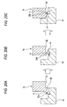
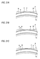
- Fig. 21 shows an eighth embodiment of the invention.
- recess portions 29 formed respectively in a plurality of portions (for example, three portions at equal intervals in a circumferential direction) of an inner circumferential surface of a fitting hole 12e of a retainer plate 7f have an angular shape.
- a bottom surface 30 of the recess portion 29 is a flat surface.
- the bottom surface 30 is disposed perpendicular to a radial direction of the fitting hole 12e at a circumferentially-intermediate portion of this recess portion 29 (that is, disposed parallel to a line tangent to this intermediate portion).
- the distance between the bottom surface 30 of the recess portion 29' and a bottom surface of a retaining recessed groove 18 (see, for example, Figs. 3 and 4 ) which retains a retaining ring 11 is larger at circumferentially-opposite end portions of the recess portion 29 than at a circumferentially-central portion thereof.
- the recess portions 29 of the above shape are provided, and therefore a force required for rotating or angularly moving the retainer plate 7f relative to an outer ring 5a can be reduced.
- the outer ring 5a is inwardly fitted in an interference manner into the holding recess 4 (see Fig. 30 ) of the housing 2, there is a possibility that phases of the through holes or screw holes 10a formed through the retainer plate 7f are slightly shifted from respective phases of the screw holes or through holes formed in the housing 2.
- the retainer plate 7f need to be angularly moved relative to the outer ring 5a, and in order to keep the force, required for the angular movement, to a low level, it is preferred that the friction between an apex portion of each larger-diameter retaining portion 17 of the retaining ring 11 and the bottom surface 30 of the recess portion 29 should be kept to a low level.
- each larger-diameter retaining portion 17 abuts against the bottom surface 30 of the recess portion 29, and then when the retainer plate 7f is angularly moved relative to the outer ring 5a in one of opposite directions, the apex portion of the larger-diameter retaining portion 17 is separated from the bottom surface 30 of the recess portion 29. Therefore, the force required for angularly moving the retainer plate 7f relative to the outer ring 5a is kept to a low level.
- each recess portion 29a is disposed in concentric relation to the outer ring 5a as shown in Fig.
- each larger-diameter retaining portion 17 still abuts against the bottom surface 30 of the recess portion 29a, so that large force is required for angularly moving the retainer plate 7f relative to the outer ring 5a.
- Figs. 23 and 24 show a ninth embodiment of the invention.
- recess portions such as larger-diameter portions 19 (see, for example, Figs. 1 to 4 ) are formed respectively at three portions of an inner circumferential surface of a fitting hole 12 of a retainer plate 7a, and also larger-diameter retaining portions 17a and 17b are formed respectively at three portions of a retaining ring 11d.
- the larger-diameter retaining portion 17a is formed at a circumferentially-intermediate (or circumferentially-central) portion of the retaining ring 11d remote from an interrupted portion 31 thereof, and the other two larger-diameter retaining portions 17b are disposed near to the interrupted portion 31.
- the amount of projecting of the larger-diameter retaining portion 17a in a radially-outward direction is smaller than the amount of projecting of each larger-diameter retaining portion 17b in the radially-outward direction.
- the amount of projecting means the distance from a circle inscribed in the retaining ring 11d to the apex of the larger-diameter retaining portion 17a, 17b as indicated by H in Fig. 24 .
- each larger-diameter retaining portion 17a, 17b is limited as described above, a force required for bringing the larger-diameter retaining portion 17a, 17b into retaining engagement with a retaining projection 15 (see, for example, Figs. 1 to 4 and 7 to 9 ) formed at the larger-diameter portion 19 can be reduced.
- the amount of projecting of the two larger-diameter retaining portions 17b and 17b disposed near to the interrupted portion 31 is relatively large, when the larger-diameter retaining portions 17a and 17b are to be brought into retaining engagement with the respective retaining projections 15, first, the two larger-diameter retaining projections 17b and 17b are engaged with the corresponding larger-diameter portions 19, and thereafter the larger-diameter retaining portion 17a remote from the interrupted portion 31 is engaged with the corresponding larger-diameter portion 19.
- the two larger-diameter retaining portions 17b and 17b are disposed near to the interrupted portion 31, and can be easily elastically deformed since those portions of a base portion (a smaller-diameter portion other than the larger-diameter retaining portions 17a and 17b) of the retaining ring 11d near to the larger-diameter retaining portions 17b and 17b can be easily displaced in the circumferential direction. Further, the larger-diameter retaining portion 17a remote from the interrupted portion 31 can not be so easily displaced in the circumferential direction, and therefore can not be so easily elastically deformed.
- the larger-diameter retaining portion formed at the circumferentially-intermediate portion of the retaining ring remote from the interrupted portion thereof is larger in the amount of radially outward projection than the other two larger-diameter retaining portions disposed near to the interrupted portion, the force required for effecting the retaining operation is increased.
- the larger-diameter retaining portion at the circumferentially-intermediate portion is first elastically compressed, and the base portion of the retaining ring is pushed toward opposite sides in the circumferential direction.
- Figs. 25 and 26 show a tenth embodiment of the invention.
- the above embodiments are based on the assumption that the outer ring 5a is fitted in the holding recess 4 (see Fig. 30 ) of the housing 2 by a sufficiently tight interference fit (so that creep will not occur even when the temperature rises), and therefore is prevented from rotation (creep) during the operation. Therefore, in the above embodiments, there is not provided any means for positively preventing a relative rotation between the outer ring 5a and the retainer plate 7a through 7f.
- an outer ring 5a is inwardly fitted in the retaining recess 4 of the housing 2 by an interference fit which does not always provide a sufficient fitting strength (which interference fit is rather close to a clearance fit or is at such a level that creep may occur when the temperature rises), but a structure for preventing a relative rotation of the outer ring 5a and a retainer plate 7g in a specified direction is provided between the outer ring 5a and the retainer plate 7g.
- a depth of each of recess portions 29b formed respectively in a plurality of portions of an inner circumferential edge of a fitting hole 12f formed through the retainer plate 7g is smaller at its one circumferential end portion (right side in Figs. 25 and 26 ), and is larger at the other circumferential end portion (left side in Figs. 25 and 26 ).
- assembling direction is restricted so that a force acts on the outer ring 5a in a clockwise direction (in Figs. 25 and 26 ).
- the showing of a retaining projection 15b (see Fig. 26 ) formed at an axial end portion of each recess portion 29b is omitted.
- the outer ring 5a and the retainer plate 7g are coupled together, and when the retainer plate 7g is rotated in the clockwise direction from a neutral condition shown in Fig. 25A , each larger-diameter retaining portion 17 of a retaining ring 11 is brought into engagement with the deeper portion of the recess portion 29b as shown in Fig. 25B . Then, the outer ring 5a having the retaining ring 11 mounted thereon is rotated together with the retainer plate 7g.
- each larger-diameter retaining portion 17 of the retaining ring 11 is brought into biting engagement with the shallower portion of the recess portion 29b as shown in Fig. 25C , and bites in a wedge-like manner into a gap between a bottom surface of the recess portion 29b and a bottom surface of a retaining recessed groove formed in an outer circumferential surface of the outer ring 5a.
- the outer ring 5a is prevented from rotation relative to the retainer plate 7g.
- the structure of this embodiment has the above construction and effects, and therefore even when the outer ring 5a is inwardly fitted in the holding recess 4 by a clearance fit or a loose interference fit which does not always provide a sufficient fitting strength, the outer ring 5a is prevented from rotation during the operation.
- the outer ring 5a even when the outer ring 5a is thus inwardly fitted in the holding recess 4 by a clearance fit or a loose interference fit, creep of the outer ring 5a can be prevented.
- the outer ring 5a may be fitted in the holding recess 4 by a sufficiently tight interference fit.
- the retainer plate 7g can be rotated relative to the outer ring 5a in the clockwise direction ( Fig. 25 ), and therefore through holes formed through this retainer plate 7g can be brought into alignment with respective screw holes formed in the housing.
- creep of the outer ring 5a can be more positively prevented.
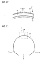
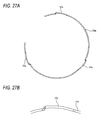
- Figs. 27 to 29 show an eleventh embodiment of the invention.
- a structure for preventing a relative rotation of the outer ring 5a and a retainer plate 7h in a specified direction is provided between the outer ring 5a and the retainer plate 7h in order to prevent the rotation of the outer ring 5a during the operation as in the above tenth embodiment.
- an projection amount of each of larger-diameter retaining portions 17c formed respectively at a plurality of circumferentially-spaced portions of a retaining ring 11e is larger at its one circumferential end portion, and is smaller at the other circumferential end portion.
- assembling direction is restricted so that a force acts on the outer ring 5a in a clockwise direction as shown in Fig. 29 .
- the showing of a retaining projection 15 (see, for example, Figs. 1 to 4 ) formed at an axial end portion of each larger-diameter portion (recess portion) 19 is omitted.
- each larger-diameter retaining portion 17c of the retaining ring 11e bites in a wedge-like manner into a gap between the other circumferential end of the larger-diameter portion 19 and a bottom surface of a retaining recessed groove formed in an outer circumferential surface of the outer ring 5a.
- the outer ring 5a is prevented from rotation relative to the retainer plate 7h.
- the structure of this embodiment has the above construction and effects, and therefore even when the outer ring 5a is fitted in the holding recess 4 by a clearance fit or a loose interference fit, the outer ring 5a is prevented from rotation during the operation as is the case with the above tenth embodiment.
- the outer ring 5a even when the outer ring 5a is thus fitted in the holding recess 4 by a clearance fit, creep of the outer ring 5a can be prevented.
- the outer ring 5a may be outwardly fitted in the holding recess 4 by a tight interference fit. Even when the outer ring 5a is thus fitted by a tight interference fit, the retainer plate 7h can be rotated relative to the outer ring 5a in the clockwise direction in Fig. 29 , and therefore through holes formed through this retainer plate 7h can be brought into alignment with respective screw holes formed in the housing.
- creep of the outer ring 5a can be more positively prevented.
- the retainer plate is connected to the outer ring of the rolling bearing in such a manner that this retainer plate can be rotated relative to the outer ring but can not be separated therefrom.
- the bearing used in the invention is not limited to the illustrated single row deep groove rolling bearing, but any other suitable rolling bearing can be used.
Landscapes
- Engineering & Computer Science (AREA)
- General Engineering & Computer Science (AREA)
- Mechanical Engineering (AREA)
- Rolling Contact Bearings (AREA)
Applications Claiming Priority (2)
| Application Number | Priority Date | Filing Date | Title |
|---|---|---|---|
| JP2007164581 | 2007-06-22 | ||
| JP2007294624A JP5136010B2 (ja) | 2007-06-22 | 2007-11-13 | 回転支持装置及び回転支持装置用転がり軸受ユニット |
Publications (2)
| Publication Number | Publication Date |
|---|---|
| EP2006561A1 true EP2006561A1 (fr) | 2008-12-24 |
| EP2006561B1 EP2006561B1 (fr) | 2010-10-20 |
Family
ID=39769379
Family Applications (1)
| Application Number | Title | Priority Date | Filing Date |
|---|---|---|---|
| EP08011377A Expired - Fee Related EP2006561B1 (fr) | 2007-06-22 | 2008-06-23 | Ensemble de roulement |
Country Status (2)
| Country | Link |
|---|---|
| US (1) | US7967512B2 (fr) |
| EP (1) | EP2006561B1 (fr) |
Cited By (6)
| Publication number | Priority date | Publication date | Assignee | Title |
|---|---|---|---|---|
| WO2011067152A1 (fr) | 2009-12-02 | 2011-06-09 | Aktiebolaget Skf | Ensemble palier |
| WO2016116105A1 (fr) * | 2015-01-22 | 2016-07-28 | Schaeffler Technologies AG & Co. KG | Agencement de palier et turbocompresseur à gaz d'échappement |
| WO2016186754A1 (fr) * | 2015-05-19 | 2016-11-24 | Schaeffler Technologies AG & Co. KG | Agencement de retenue pour palier à roulement |
| CN106609803A (zh) * | 2015-10-26 | 2017-05-03 | 广州汽车集团股份有限公司 | 轴承组件装配方法和变速器总成装配方法 |
| DE102018120033A1 (de) * | 2018-08-17 | 2019-07-18 | Schaeffler Technologies AG & Co. KG | Formschlüssige Sicherungsanordnung und Montageverfahren |
| WO2020007394A1 (fr) | 2018-07-03 | 2020-01-09 | Schaeffler Technologies AG & Co. KG | Ensemble de palier et élément de bague de retenue prévu à cet effet |
Families Citing this family (8)
| Publication number | Priority date | Publication date | Assignee | Title |
|---|---|---|---|---|
| DE102007027161A1 (de) * | 2007-06-13 | 2008-12-18 | Schaeffler Kg | Lageranordnung |
| JP2011012796A (ja) * | 2009-07-06 | 2011-01-20 | Ntn Corp | 回転センサ付軸受 |
| US9438089B2 (en) * | 2014-03-06 | 2016-09-06 | Baker Hughes Incorporated | Systems and methods for preventing rotation of rotor bearings in a stator |
| US10683868B2 (en) * | 2016-07-18 | 2020-06-16 | Halliburton Energy Services, Inc. | Bushing anti-rotation system and apparatus |
| DE102017211792A1 (de) * | 2017-07-10 | 2019-01-10 | Aktiebolaget Skf | Verfahren zur Befestigung eines Lagerträgers und Anordnung |
| JP6914594B2 (ja) * | 2017-08-09 | 2021-08-04 | ヤマハ発動機株式会社 | 駆動ユニットおよび電動補助自転車 |
| DE102018119256B4 (de) * | 2017-09-05 | 2024-03-14 | Schaeffler Technologies AG & Co. KG | Lagereinheit |
| US10837487B2 (en) * | 2018-03-29 | 2020-11-17 | Transportation Ip Holdings, Llc | Bearing assembly and method |
Citations (5)
| Publication number | Priority date | Publication date | Assignee | Title |
|---|---|---|---|---|
| DE2658157A1 (de) * | 1976-12-22 | 1978-06-29 | Zahnradfabrik Friedrichshafen | Axiale fixierung fuer waelzlager |
| DE20019278U1 (de) | 2000-11-13 | 2001-04-05 | Skf Gmbh | Verbindung zwischen einem Trägerelement und einem Lager |
| JP2005220990A (ja) * | 2004-02-05 | 2005-08-18 | Koyo Seiko Co Ltd | 軸受装置 |
| DE102005012323B3 (de) | 2005-03-17 | 2006-06-01 | Ab Skf | Lageranordnung |
| JP2007504412A (ja) | 2003-09-03 | 2007-03-01 | エヌエスケイ ヨーロッパ リミテッド | 軸受アセンブリ |
Family Cites Families (4)
| Publication number | Priority date | Publication date | Assignee | Title |
|---|---|---|---|---|
| US2277635A (en) * | 1939-08-17 | 1942-03-24 | Gen Motors Corp | Bearing mounting |
| US2607642A (en) * | 1946-10-25 | 1952-08-19 | Bendix Aviat Corp | Antifriction bearing and associated member |
| US3888597A (en) * | 1972-02-24 | 1975-06-10 | Int Harvester Co | Retaining assembly |
| US4511191A (en) * | 1984-02-14 | 1985-04-16 | Koyo Seike Company Limited | Anticreep device for annular member |
-
2008
- 2008-06-23 EP EP08011377A patent/EP2006561B1/fr not_active Expired - Fee Related
- 2008-06-23 US US12/144,126 patent/US7967512B2/en not_active Expired - Fee Related
Patent Citations (5)
| Publication number | Priority date | Publication date | Assignee | Title |
|---|---|---|---|---|
| DE2658157A1 (de) * | 1976-12-22 | 1978-06-29 | Zahnradfabrik Friedrichshafen | Axiale fixierung fuer waelzlager |
| DE20019278U1 (de) | 2000-11-13 | 2001-04-05 | Skf Gmbh | Verbindung zwischen einem Trägerelement und einem Lager |
| JP2007504412A (ja) | 2003-09-03 | 2007-03-01 | エヌエスケイ ヨーロッパ リミテッド | 軸受アセンブリ |
| JP2005220990A (ja) * | 2004-02-05 | 2005-08-18 | Koyo Seiko Co Ltd | 軸受装置 |
| DE102005012323B3 (de) | 2005-03-17 | 2006-06-01 | Ab Skf | Lageranordnung |
Cited By (11)
| Publication number | Priority date | Publication date | Assignee | Title |
|---|---|---|---|---|
| WO2011067152A1 (fr) | 2009-12-02 | 2011-06-09 | Aktiebolaget Skf | Ensemble palier |
| US8967877B2 (en) | 2009-12-02 | 2015-03-03 | Aktiebolaget Skf | Bearing arrangement |
| WO2016116105A1 (fr) * | 2015-01-22 | 2016-07-28 | Schaeffler Technologies AG & Co. KG | Agencement de palier et turbocompresseur à gaz d'échappement |
| CN107109963A (zh) * | 2015-01-22 | 2017-08-29 | 舍弗勒技术股份两合公司 | 轴承装置和废气涡轮增压器 |
| US10132350B2 (en) | 2015-01-22 | 2018-11-20 | Schaeffler Technologies AG & Co. KG | Bearing assembly and exhaust gas turbocharger |
| CN107109963B (zh) * | 2015-01-22 | 2020-02-07 | 舍弗勒技术股份两合公司 | 轴承装置和废气涡轮增压器 |
| WO2016186754A1 (fr) * | 2015-05-19 | 2016-11-24 | Schaeffler Technologies AG & Co. KG | Agencement de retenue pour palier à roulement |
| US9810267B2 (en) | 2015-05-19 | 2017-11-07 | Schaeffler Technologies AG & Co. KG | Retention arrangement for a rolling element bearing |
| CN106609803A (zh) * | 2015-10-26 | 2017-05-03 | 广州汽车集团股份有限公司 | 轴承组件装配方法和变速器总成装配方法 |
| WO2020007394A1 (fr) | 2018-07-03 | 2020-01-09 | Schaeffler Technologies AG & Co. KG | Ensemble de palier et élément de bague de retenue prévu à cet effet |
| DE102018120033A1 (de) * | 2018-08-17 | 2019-07-18 | Schaeffler Technologies AG & Co. KG | Formschlüssige Sicherungsanordnung und Montageverfahren |
Also Published As
| Publication number | Publication date |
|---|---|
| EP2006561B1 (fr) | 2010-10-20 |
| US20090052826A1 (en) | 2009-02-26 |
| US7967512B2 (en) | 2011-06-28 |
Similar Documents
| Publication | Publication Date | Title |
|---|---|---|
| EP2006561B1 (fr) | Ensemble de roulement | |
| US8517389B2 (en) | Fixing arrangement for a rubber seal for sealing a rolling bearing | |
| JP6610922B2 (ja) | モータ内蔵ローラ、及び動力伝達部材 | |
| US7303367B2 (en) | Lock nut system | |
| US20030103704A1 (en) | Bearing retention assembly having cam chamfered bearing race ring | |
| US8961029B2 (en) | Roller thrust bearing | |
| US5735171A (en) | Pivot joint with retainer clip | |
| EP3014135B1 (fr) | Anneau de tolérance doté d'un élément de verrouillage | |
| US7124868B2 (en) | One-way clutch device and method for manufacturing the same | |
| EP1731779A1 (fr) | Procédé d"assemblage pour dispositif porteur | |
| WO2007013316A1 (fr) | Palier a roulements a aiguilles et structure a palier | |
| US11767917B2 (en) | Press-in retainer ring | |
| US7037200B2 (en) | Coupling arrangement | |
| US20060193549A1 (en) | Thrust bearing comprising a spacing member | |
| US8967877B2 (en) | Bearing arrangement | |
| WO2016017629A1 (fr) | Palier de butée et procédé de fabrication associé | |
| JP5091314B2 (ja) | 膨張部材を備えるシャフトハブ組立体 | |
| JP5136010B2 (ja) | 回転支持装置及び回転支持装置用転がり軸受ユニット | |
| US20060090978A1 (en) | Overrunning clutch | |
| EP1857693A2 (fr) | Roulement à billes à douille | |
| JP5140152B2 (ja) | 軸受カップに支持されるコンベヤーローラ | |
| JP2009030794A5 (fr) | ||
| EP0716939A1 (fr) | Ensemble de moyen avec connexion du type rondelle Belleville | |
| EP0735289A2 (fr) | Bouclier pour palier à roulement | |
| US6591955B2 (en) | Freewheel device |
Legal Events
| Date | Code | Title | Description |
|---|---|---|---|
| PUAI | Public reference made under article 153(3) epc to a published international application that has entered the european phase |
Free format text: ORIGINAL CODE: 0009012 |
|
| AK | Designated contracting states |
Kind code of ref document: A1 Designated state(s): AT BE BG CH CY CZ DE DK EE ES FI FR GB GR HR HU IE IS IT LI LT LU LV MC MT NL NO PL PT RO SE SI SK TR |
|
| AX | Request for extension of the european patent |
Extension state: AL BA MK RS |
|
| 17P | Request for examination filed |
Effective date: 20090623 |
|
| AKX | Designation fees paid |
Designated state(s): DE |
|
| 17Q | First examination report despatched |
Effective date: 20091228 |
|
| GRAP | Despatch of communication of intention to grant a patent |
Free format text: ORIGINAL CODE: EPIDOSNIGR1 |
|
| GRAS | Grant fee paid |
Free format text: ORIGINAL CODE: EPIDOSNIGR3 |
|
| GRAA | (expected) grant |
Free format text: ORIGINAL CODE: 0009210 |
|
| AK | Designated contracting states |
Kind code of ref document: B1 Designated state(s): DE |
|
| REF | Corresponds to: |
Ref document number: 602008003059 Country of ref document: DE Date of ref document: 20101202 Kind code of ref document: P |
|
| PLBE | No opposition filed within time limit |
Free format text: ORIGINAL CODE: 0009261 |
|
| STAA | Information on the status of an ep patent application or granted ep patent |
Free format text: STATUS: NO OPPOSITION FILED WITHIN TIME LIMIT |
|
| 26N | No opposition filed |
Effective date: 20110721 |
|
| REG | Reference to a national code |
Ref country code: DE Ref legal event code: R097 Ref document number: 602008003059 Country of ref document: DE Effective date: 20110721 |
|
| PGFP | Annual fee paid to national office [announced via postgrant information from national office to epo] |
Ref country code: DE Payment date: 20190612 Year of fee payment: 12 |
|
| REG | Reference to a national code |
Ref country code: DE Ref legal event code: R119 Ref document number: 602008003059 Country of ref document: DE |
|
| PG25 | Lapsed in a contracting state [announced via postgrant information from national office to epo] |
Ref country code: DE Free format text: LAPSE BECAUSE OF NON-PAYMENT OF DUE FEES Effective date: 20210101 |