EP2006507A1 - Réglage d'un système de charge pour moteurs à combustion interne - Google Patents
Réglage d'un système de charge pour moteurs à combustion interne Download PDFInfo
- Publication number
- EP2006507A1 EP2006507A1 EP07110902A EP07110902A EP2006507A1 EP 2006507 A1 EP2006507 A1 EP 2006507A1 EP 07110902 A EP07110902 A EP 07110902A EP 07110902 A EP07110902 A EP 07110902A EP 2006507 A1 EP2006507 A1 EP 2006507A1
- Authority
- EP
- European Patent Office
- Prior art keywords
- exhaust gas
- turbochargers
- turbine
- turbocharger
- geometry
- Prior art date
- Legal status (The legal status is an assumption and is not a legal conclusion. Google has not performed a legal analysis and makes no representation as to the accuracy of the status listed.)
- Withdrawn
Links
Images
Classifications
-
- F—MECHANICAL ENGINEERING; LIGHTING; HEATING; WEAPONS; BLASTING
- F02—COMBUSTION ENGINES; HOT-GAS OR COMBUSTION-PRODUCT ENGINE PLANTS
- F02B—INTERNAL-COMBUSTION PISTON ENGINES; COMBUSTION ENGINES IN GENERAL
- F02B37/00—Engines characterised by provision of pumps driven at least for part of the time by exhaust
- F02B37/007—Engines characterised by provision of pumps driven at least for part of the time by exhaust with exhaust-driven pumps arranged in parallel, e.g. at least one pump supplying alternatively
-
- F—MECHANICAL ENGINEERING; LIGHTING; HEATING; WEAPONS; BLASTING
- F02—COMBUSTION ENGINES; HOT-GAS OR COMBUSTION-PRODUCT ENGINE PLANTS
- F02B—INTERNAL-COMBUSTION PISTON ENGINES; COMBUSTION ENGINES IN GENERAL
- F02B37/00—Engines characterised by provision of pumps driven at least for part of the time by exhaust
- F02B37/04—Engines with exhaust drive and other drive of pumps, e.g. with exhaust-driven pump and mechanically-driven second pump
- F02B37/10—Engines with exhaust drive and other drive of pumps, e.g. with exhaust-driven pump and mechanically-driven second pump at least one pump being alternatively or simultaneously driven by exhaust and other drive, e.g. by pressurised fluid from a reservoir or an engine-driven pump
-
- F—MECHANICAL ENGINEERING; LIGHTING; HEATING; WEAPONS; BLASTING
- F02—COMBUSTION ENGINES; HOT-GAS OR COMBUSTION-PRODUCT ENGINE PLANTS
- F02B—INTERNAL-COMBUSTION PISTON ENGINES; COMBUSTION ENGINES IN GENERAL
- F02B37/00—Engines characterised by provision of pumps driven at least for part of the time by exhaust
- F02B37/12—Control of the pumps
- F02B37/24—Control of the pumps by using pumps or turbines with adjustable guide vanes
-
- F—MECHANICAL ENGINEERING; LIGHTING; HEATING; WEAPONS; BLASTING
- F02—COMBUSTION ENGINES; HOT-GAS OR COMBUSTION-PRODUCT ENGINE PLANTS
- F02B—INTERNAL-COMBUSTION PISTON ENGINES; COMBUSTION ENGINES IN GENERAL
- F02B39/00—Component parts, details, or accessories relating to, driven charging or scavenging pumps, not provided for in groups F02B33/00 - F02B37/00
- F02B39/02—Drives of pumps; Varying pump drive gear ratio
- F02B39/08—Non-mechanical drives, e.g. fluid drives having variable gear ratio
- F02B39/10—Non-mechanical drives, e.g. fluid drives having variable gear ratio electric
-
- Y—GENERAL TAGGING OF NEW TECHNOLOGICAL DEVELOPMENTS; GENERAL TAGGING OF CROSS-SECTIONAL TECHNOLOGIES SPANNING OVER SEVERAL SECTIONS OF THE IPC; TECHNICAL SUBJECTS COVERED BY FORMER USPC CROSS-REFERENCE ART COLLECTIONS [XRACs] AND DIGESTS
- Y02—TECHNOLOGIES OR APPLICATIONS FOR MITIGATION OR ADAPTATION AGAINST CLIMATE CHANGE
- Y02T—CLIMATE CHANGE MITIGATION TECHNOLOGIES RELATED TO TRANSPORTATION
- Y02T10/00—Road transport of goods or passengers
- Y02T10/10—Internal combustion engine [ICE] based vehicles
- Y02T10/12—Improving ICE efficiencies
Definitions
- the invention relates to the field of supercharged by exhaust gas turbochargers internal combustion engines. It relates to the regulation of a charging system for an internal combustion engine with multiple exhaust gas turbochargers.
- multiple exhaust gas turbochargers or exhaust gas turbocharger groups - ie series-connected low-pressure and high-pressure turbocharger, with several low-pressure exhaust gas turbochargers in a common high-pressure turbocharger promote or multiple high-pressure turbocharger are fed by a low-pressure exhaust gas turbocharger can - be used in parallel operation.
- the compressors of the plurality of exhaust gas turbochargers usually convey the compressors air into a common air receiver
- Deviations in the technical equipment, the size or the performance of the individual exhaust gas turbochargers can lead to different operating states of the exhaust gas turbocharger in stationary or in transient operation.
- the different operating states can lead to impermissible loads for individual exhaust gas turbochargers, for example due to pumps or due to excessive rotational speeds.
- turbochargers of the same design are generally used today on an engine.
- the exhaust gas turbocharger In order to improve either the partial load behavior or the transient behavior of the system engine and exhaust gas turbocharger or to enable energy extraction at full load, the exhaust gas turbocharger with an electric machine, a variable geometry exhaust gas turbine (VTG), with a compressor blowing, with an adjustable Ver emphasizervorrad (VCG variable compressor geometry) or a combination thereof.
- VFG variable compressor geometry variable compressor geometry
- the regulation according to the invention corrects the deviations of the operating states, compensates for disturbances which act from outside on individual exhaust-gas turbochargers and takes into account the performance differences resulting from the operation or the mounting situation.
- the regulation according to the invention now makes it possible to control the additional devices in such a way that an undesired drift apart of the operating points of the various exhaust-gas turbochargers operated in parallel is prevented.
- the scheme is intended to approximate or equalize the operating points of the individual exhaust gas turbochargers, to compensate for disturbances and performance impairments of the exhaust gas turbocharger and optionally set a desired operating point.
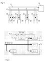
- Fig. 1 shows a charging system for an internal combustion engine 10 with four turbochargers.
- Each of the exhaust gas turbochargers comprises a compressor 20 and an exhaust gas turbine.
- a differentiation is made in the exhaust gas turbines between the conventional exhaust gas turbines 30 and the exhaust gas turbines 31 equipped with adjustable guide geometry.
- a first exhaust gas turbocharger is connected to an electric machine (motor / generator), with which the exhaust gas turbocharger shaft can either be accelerated or braked. When accelerating electrical energy must be expended, during braking, electrical energy can be obtained.
- pneumatic or mechanical drives / outputs can be used. This applies analogously to the other embodiments.
- the same exhaust gas turbocharger is equipped with an exhaust gas turbine 31 with adjustable guide geometry. The remaining turbochargers are equipped without additional equipment (electric machine, adjustable turbine guidance geometry).
- the engine control regulates or controls the power of the electric machine so that either electrical energy is obtained while maintaining a lower limit for the pressure in the air receiver or the exhaust gas turbocharger is driven, so that sets a desired pressure in the air receiver. Due to the intervention of the engine control, the operating point of the exhaust gas turbocharger equipped with the electric machine may be changed inadmissibly.
- the regulation according to the invention uses the regulator 1 according to Fig. 2 a representative of the operating point size of Exhaust gas turbocharger, eg the volume flow ( V ⁇ ref ) or the speed of the turbochargers without additional equipment (2. TL and 3. TL) from, and provides an actuator the position of the turbine vanes (u VTG ) of the exhaust gas turbocharger with electric machine and adjustable turbines -Leitgeometrie (1st TL) so that for this exhaust gas turbocharger the same operating point results as for the other turbochargers without additional equipment.
- a compressor bypass (bypass) with an adjustable valve or flap can be used (u Byp ).
- the desired operating point is predetermined by those exhaust gas turbochargers which are not equipped with adjustable turbine guide geometry.
- the control compensates for disturbances, such as the unknown electrical power of the electrical machine. If at least the temperature (T VA ) is measured after the compressor, a measure of the compressor efficiency can be determined from this.
- T VA temperature
- the compressor efficiency is used to correct the desired operating point so that the control does not unnecessarily shift the operating point of the compressor toward the surge line.
- different geometric dimensions, other thermodynamic parameters and other parameters for the correction of the desired operating point can be used.
- the regulation according to the invention comprises two regulators.
- One of the regulators receives from the control of the internal combustion engine a signal which is representative of a desired operating point, for example the desired pressure in the air receiver (p rec, ref ).
- This controller determines the power of the electric machine (U PTI / PTO ) so that the desired pressure in the air receiver is set.
- Another controller takes over, as described in the first embodiment, the control of the synchronization of the plurality of exhaust gas turbochargers with each other.
- the two controllers can operate independently of each other or be connected in series as a cascade controller, it does not matter which controller represents the outer or inner cascade.
- the controllers are robust enough to carry out, since they will affect each other during operation.
- the two controllers can also be combined in a so-called MIMO controller (multiple input multiple output). In this case, the mutual influence is taken directly into the controller by appropriate design and the stability of the control system is not adversely affected.
- the two controllers can also be reversed so that the desired operating point is adjusted by controlling the adjustable turbine guide.
- the second control affects the performance of the electric machine with the aim of matching the operating conditions of the individual exhaust gas turbochargers with each other by targeted addition / removal of electrical power.
- the representative variable for the operating point to be set can be, in addition to the air receiver pressure, the power of the electrical machine, the areas of the turbine guidance geometry or the purge pressure gradient across the engine.
- the efficiency of the compressor of the individual exhaust gas turbocharger may change differently.
- parallel operated exhaust gas turbochargers with common air receiver has an efficiency reduction on the compressor of an exhaust gas turbocharger an increase in speed and a reduction in the flow rate of the compressor in question.
- a change in the efficiency can be determined.
- the calculated from the measured signals change in the compressor efficiency is used to determine a corrected target operating point of the exhaust gas turbocharger.
- the regulation then takes over the task of preventing the operating point of the compressor concerned from undesirably moving away from its desired operating point.
- the efficiency of the exhaust gas turbocharger for each or each of the exhaust gas turbocharger can be determined. It can then be realized a regulation that adjusts the absolute operating point of the exhaust gas turbocharger, for which purpose, a regulator path is provided per exhaust gas turbocharger.
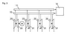
- Fig. 3 shows a second charging system for an internal combustion engine 10, in turn with four exhaust gas turbochargers.
- Each of the exhaust gas turbochargers comprises a compressor 20 and an exhaust gas turbine.
- a first exhaust gas turbocharger is connected to an electric machine.
- the exhaust gas turbine of the exhaust gas turbocharger connected to the electric machine does not have an adjustable guide geometry, but the exhaust gas turbines of all the other exhaust gas turbochargers.
- the operating point of the first exhaust gas turbocharger which is coupled to the electric machine, depending on the engine operating point and Other parameters such as environment, engine or exhaust gas turbocharger pollution, electricity needs of the recipients and electricity production of other producers or power supply depending on the needs of the other recipients and the power of the generators by the output or drive torque of this machine controlled or regulated.
- the turbine surface of the exhaust gas turbines equipped with adjustable guide geometry is reduced or enlarged in such a way that these exhaust gas turbochargers reach a certain operating point.
- the operating point of the remaining exhaust-gas turbochargers can thereby be matched to that of the exhaust-gas turbocharger which is coupled to the electric machine.
- the regulation according to the invention can also be applied to a charging system which consists of two groups of exhaust-gas turbochargers, which are thermodynamically similarly configured in themselves. All turbochargers work in parallel.
- the exhaust gas turbocharger of the first group are equipped with either an electric machine and an adjustable turbine guide or only with one electric machine.
- the exhaust gas turbocharger of the second group are all equipped with an adjustable turbine guide.
- the control can also be applied to charging systems which do not use an electric machine but one or more turbochargers are equipped with adjustable turbine guide.
- one or more turbochargers are equipped with adjustable turbine guide.
- an exhaust gas turbocharger is equipped with an electric machine and adjustable turbine guide device and all other exhaust gas turbochargers only with an adjustable turbine guide device.
- the turbochargers can be of different sizes.
- one of the parallel-operating high-pressure stages can be equipped with an electric machine and adjustable turbine guide device or, as in the first embodiment, a high-pressure stage with one electric machine and all other high-pressure stages are equipped with adjustable turbine guide.
- the control is then applied analogously to the 1-stage charging to the high-pressure stages of the 2-stage charging.
- a charging system register charging is used.
- the turbochargers are typically of different sizes and may be switched on or off individually.
- the control has the task, in particular during transient operating phases, of compensating for the different acceleration behavior of the exhaust gas turbochargers.
Priority Applications (5)
| Application Number | Priority Date | Filing Date | Title |
|---|---|---|---|
| EP07110902A EP2006507A1 (fr) | 2007-06-22 | 2007-06-22 | Réglage d'un système de charge pour moteurs à combustion interne |
| JP2010512715A JP5080643B2 (ja) | 2007-06-22 | 2008-06-23 | 内燃機械用のスーパーチャージャ・システムの制御装置 |
| KR1020107001075A KR101197065B1 (ko) | 2007-06-22 | 2008-06-23 | 내연기관을 위한 과급 시스템의 조절 |
| EP08774223A EP2171236A1 (fr) | 2007-06-22 | 2008-06-23 | Régulation d'un système de suralimentation pour moteurs à combustion interne |
| PCT/EP2008/057957 WO2009000807A1 (fr) | 2007-06-22 | 2008-06-23 | Régulation d'un système de suralimentation pour moteurs à combustion interne |
Applications Claiming Priority (1)
| Application Number | Priority Date | Filing Date | Title |
|---|---|---|---|
| EP07110902A EP2006507A1 (fr) | 2007-06-22 | 2007-06-22 | Réglage d'un système de charge pour moteurs à combustion interne |
Publications (1)
| Publication Number | Publication Date |
|---|---|
| EP2006507A1 true EP2006507A1 (fr) | 2008-12-24 |
Family
ID=38697523
Family Applications (2)
| Application Number | Title | Priority Date | Filing Date |
|---|---|---|---|
| EP07110902A Withdrawn EP2006507A1 (fr) | 2007-06-22 | 2007-06-22 | Réglage d'un système de charge pour moteurs à combustion interne |
| EP08774223A Withdrawn EP2171236A1 (fr) | 2007-06-22 | 2008-06-23 | Régulation d'un système de suralimentation pour moteurs à combustion interne |
Family Applications After (1)
| Application Number | Title | Priority Date | Filing Date |
|---|---|---|---|
| EP08774223A Withdrawn EP2171236A1 (fr) | 2007-06-22 | 2008-06-23 | Régulation d'un système de suralimentation pour moteurs à combustion interne |
Country Status (4)
| Country | Link |
|---|---|
| EP (2) | EP2006507A1 (fr) |
| JP (1) | JP5080643B2 (fr) |
| KR (1) | KR101197065B1 (fr) |
| WO (1) | WO2009000807A1 (fr) |
Cited By (3)
| Publication number | Priority date | Publication date | Assignee | Title |
|---|---|---|---|---|
| EP2463496A1 (fr) * | 2010-12-10 | 2012-06-13 | Perkins Engines Company Limited | Contrôle de turbocompresseur multiple |
| WO2012113425A1 (fr) * | 2011-02-26 | 2012-08-30 | Daimler Ag | Ensemble turbocompresseur à gaz d'échappement |
| EP3228841A4 (fr) * | 2015-01-30 | 2018-06-06 | Mitsubishi Heavy Industries, Ltd. | Système de suralimentation, dispositif de commande pour système de suralimentation, et procédé de fonctionnement de système de suralimentation |
Citations (9)
| Publication number | Priority date | Publication date | Assignee | Title |
|---|---|---|---|---|
| GB267149A (en) * | 1926-03-08 | 1927-08-18 | Alfred Buchi | Improvements in means for supplying the charge in internal combustion engines |
| GB1261335A (en) * | 1969-04-16 | 1972-01-26 | Tzadok Zakon | Improvement in supercharged two stroke diesel engines |
| DE2609389A1 (de) * | 1976-03-06 | 1977-09-08 | Maschf Augsburg Nuernberg Ag | Abgasturboladeraggregat |
| DE19827627A1 (de) * | 1998-06-20 | 1999-12-23 | Daimler Chrysler Ag | Verfahren und Vorrichtung zur Regelung einer aufgeladenen Brennkraftmaschine |
| EP1336737A2 (fr) * | 2002-02-18 | 2003-08-20 | Toyota Jidosha Kabushiki Kaisha | Dispositif et procédé de commande de pression de suralimentation |
| DE10224686A1 (de) * | 2002-06-04 | 2003-12-18 | Bosch Gmbh Robert | Verfahren und Vorrichtung zur Regelung des Ladedrucks mindestens zweier Verdichter einer Brennkraftmaschine |
| EP1498594A1 (fr) * | 2003-07-16 | 2005-01-19 | Toyota Jidosha Kabushiki Kaisha | Dispositif de contrôle de l'échappement d'un moteur à combustion interne et methode d'estimation de la quantité du débit de gaz d'échappement |
| WO2005059317A1 (fr) * | 2003-12-10 | 2005-06-30 | Honeywell International Inc. | Dispositif a buse variable pour turbocompresseur |
| WO2007020524A1 (fr) * | 2005-08-19 | 2007-02-22 | Toyota Jidosha Kabushiki Kaisha | Commande de pression d'admission |
Family Cites Families (9)
| Publication number | Priority date | Publication date | Assignee | Title |
|---|---|---|---|---|
| JPH03267525A (ja) * | 1990-03-19 | 1991-11-28 | Toyota Motor Corp | 過給機付エンジン |
| JP2884725B2 (ja) * | 1990-06-21 | 1999-04-19 | いすゞ自動車株式会社 | ツインターボチャージャの制御装置 |
| DE4416572C1 (de) * | 1994-05-11 | 1995-04-27 | Daimler Benz Ag | Aufgeladene Brennkraftmaschine |
| US6550247B1 (en) * | 2001-08-30 | 2003-04-22 | Caterpillar Inc | Multiple parallel turbocharger control with discrete step nozzles |
| DE10235701B3 (de) * | 2002-08-03 | 2004-04-15 | UDO MAILäNDER GMBH | Aufgeladene Brennkraftmaschine |
| JP4483278B2 (ja) * | 2003-12-04 | 2010-06-16 | トヨタ自動車株式会社 | 複数過給機を備える内燃機関 |
| JP4438521B2 (ja) * | 2004-06-03 | 2010-03-24 | トヨタ自動車株式会社 | 複数のターボチャージャを備えた多気筒内燃機関 |
| JP2006097542A (ja) * | 2004-09-29 | 2006-04-13 | Nissan Motor Co Ltd | 可変過給システムの過給圧調整装置 |
| US7571608B2 (en) | 2005-11-28 | 2009-08-11 | General Electric Company | Turbocharged engine system and method of operation |
-
2007
- 2007-06-22 EP EP07110902A patent/EP2006507A1/fr not_active Withdrawn
-
2008
- 2008-06-23 WO PCT/EP2008/057957 patent/WO2009000807A1/fr active Application Filing
- 2008-06-23 JP JP2010512715A patent/JP5080643B2/ja not_active Expired - Fee Related
- 2008-06-23 EP EP08774223A patent/EP2171236A1/fr not_active Withdrawn
- 2008-06-23 KR KR1020107001075A patent/KR101197065B1/ko not_active IP Right Cessation
Patent Citations (9)
| Publication number | Priority date | Publication date | Assignee | Title |
|---|---|---|---|---|
| GB267149A (en) * | 1926-03-08 | 1927-08-18 | Alfred Buchi | Improvements in means for supplying the charge in internal combustion engines |
| GB1261335A (en) * | 1969-04-16 | 1972-01-26 | Tzadok Zakon | Improvement in supercharged two stroke diesel engines |
| DE2609389A1 (de) * | 1976-03-06 | 1977-09-08 | Maschf Augsburg Nuernberg Ag | Abgasturboladeraggregat |
| DE19827627A1 (de) * | 1998-06-20 | 1999-12-23 | Daimler Chrysler Ag | Verfahren und Vorrichtung zur Regelung einer aufgeladenen Brennkraftmaschine |
| EP1336737A2 (fr) * | 2002-02-18 | 2003-08-20 | Toyota Jidosha Kabushiki Kaisha | Dispositif et procédé de commande de pression de suralimentation |
| DE10224686A1 (de) * | 2002-06-04 | 2003-12-18 | Bosch Gmbh Robert | Verfahren und Vorrichtung zur Regelung des Ladedrucks mindestens zweier Verdichter einer Brennkraftmaschine |
| EP1498594A1 (fr) * | 2003-07-16 | 2005-01-19 | Toyota Jidosha Kabushiki Kaisha | Dispositif de contrôle de l'échappement d'un moteur à combustion interne et methode d'estimation de la quantité du débit de gaz d'échappement |
| WO2005059317A1 (fr) * | 2003-12-10 | 2005-06-30 | Honeywell International Inc. | Dispositif a buse variable pour turbocompresseur |
| WO2007020524A1 (fr) * | 2005-08-19 | 2007-02-22 | Toyota Jidosha Kabushiki Kaisha | Commande de pression d'admission |
Cited By (6)
| Publication number | Priority date | Publication date | Assignee | Title |
|---|---|---|---|---|
| EP2463496A1 (fr) * | 2010-12-10 | 2012-06-13 | Perkins Engines Company Limited | Contrôle de turbocompresseur multiple |
| WO2012076726A1 (fr) * | 2010-12-10 | 2012-06-14 | Perkins Engine Company Limited | Commande de turbocompresseur multiple |
| US9726187B2 (en) | 2010-12-10 | 2017-08-08 | Perkins Engines Company Limited | Multiple turbocharger control |
| WO2012113425A1 (fr) * | 2011-02-26 | 2012-08-30 | Daimler Ag | Ensemble turbocompresseur à gaz d'échappement |
| EP3228841A4 (fr) * | 2015-01-30 | 2018-06-06 | Mitsubishi Heavy Industries, Ltd. | Système de suralimentation, dispositif de commande pour système de suralimentation, et procédé de fonctionnement de système de suralimentation |
| US10753272B2 (en) | 2015-01-30 | 2020-08-25 | Mitsubishi Heavy Industries, Ltd. | Engine supercharger for maintaining a battery charge |
Also Published As
| Publication number | Publication date |
|---|---|
| WO2009000807A1 (fr) | 2008-12-31 |
| JP2010530937A (ja) | 2010-09-16 |
| KR20100022112A (ko) | 2010-02-26 |
| KR101197065B1 (ko) | 2012-11-06 |
| EP2171236A1 (fr) | 2010-04-07 |
| JP5080643B2 (ja) | 2012-11-21 |
Similar Documents
| Publication | Publication Date | Title |
|---|---|---|
| DE102010016708B4 (de) | Verfahren im Zusammenhang mit der Steuerung und dem Betrieb einer Gasturbine | |
| EP2394041B1 (fr) | Moteur à combustion interne | |
| WO2002004799A1 (fr) | Procede permettant de reguler la pression d'admission dans un moteur thermique dote d'un turbocompresseur a gaz d'echappement | |
| WO2012097389A2 (fr) | Procédé pour faire fonctionner un moteur à combustion interne disposant d'au moins deux cylindres | |
| DE3201010A1 (de) | Vorrichtung zum einregulieren der arbeitstemperaturen und zum synchronisieren der leitradgeschwindigkeiten von turbinen | |
| DE102008044470A1 (de) | Turbinenanlage mit modulierter Brenn- und Nachbrennkammer | |
| DE3040139A1 (de) | Regelsystem fuer eine gasturbine | |
| DE60114979T2 (de) | Regelsystem für einen Turbolader variabler Geometrie | |
| EP3722573A1 (fr) | Procédé de fonctionnement d'un moteur à combustion interne doté d'un turbocompresseur à gaz d'échappement et d'un compresseur alimenté électriquement et ses dispositifs | |
| EP2006507A1 (fr) | Réglage d'un système de charge pour moteurs à combustion interne | |
| WO2020164948A1 (fr) | Procédé pour faire fonctionner un turbocompresseur | |
| WO2009000804A2 (fr) | Turbocompresseur à gaz d'échappement | |
| DE102012019896A1 (de) | Brennkraftmaschine | |
| EP2006514B1 (fr) | Moteur à combustion interne fixe | |
| EP3097293A1 (fr) | Régulation variable de la puissance limite de turbines à gaz | |
| AT516613B1 (de) | Verfahren zum betreiben einer brennkraftmaschine | |
| EP2037099B1 (fr) | Moteurs à combustion interne et dispositif de réglage de moteur | |
| DE102019216576A1 (de) | Verfahren zum Betreiben einer Brennkraftmaschine und Brennkraftmaschine zur Durchführung eines solchen Verfahrens | |
| WO2018059810A1 (fr) | Procédé pour faire fonctionner un équipement bi-turbo et unité de commande de moteur | |
| DE102015014810B4 (de) | Verfahren zum Betreiben einer Antriebseinrichtung für ein Kraftfahrzeug sowie entsprechende Antriebseinrichtung | |
| EP2963265A1 (fr) | Procédé et dispositif de fonctionnement d'une turbosoufflante de gaz d'échappement | |
| WO2009056636A1 (fr) | Régulation d'un turbocompresseur | |
| WO2023161065A1 (fr) | Dispositif de commande pour un moteur à combustion interne, ensemble moteur à combustion interne comprenant un moteur à combustion interne et un tel dispositif de commande, procédé de fonctionnement d'un moteur à combustion interne et procédé de détermination d'une carte de caractéristiques de composant | |
| DE102011108766A1 (de) | Verfahren zum Verändern der Drehzahl eines Turbogastriebwerks und Triebwerkscontroller | |
| EP2907989A1 (fr) | Fonctionnement d'une installation de turbine à gaz comprenant un compresseur et une turbine |
Legal Events
| Date | Code | Title | Description |
|---|---|---|---|
| PUAI | Public reference made under article 153(3) epc to a published international application that has entered the european phase |
Free format text: ORIGINAL CODE: 0009012 |
|
| AK | Designated contracting states |
Kind code of ref document: A1 Designated state(s): AT BE BG CH CY CZ DE DK EE ES FI FR GB GR HU IE IS IT LI LT LU LV MC MT NL PL PT RO SE SI SK TR |
|
| AX | Request for extension of the european patent |
Extension state: AL BA HR MK RS |
|
| AKX | Designation fees paid | ||
| REG | Reference to a national code |
Ref country code: DE Ref legal event code: 8566 |
|
| STAA | Information on the status of an ep patent application or granted ep patent |
Free format text: STATUS: THE APPLICATION IS DEEMED TO BE WITHDRAWN |
|
| 18D | Application deemed to be withdrawn |
Effective date: 20090625 |