EP2006507A1 - Control of a charging system for combustion engines - Google Patents
Control of a charging system for combustion engines Download PDFInfo
- Publication number
- EP2006507A1 EP2006507A1 EP07110902A EP07110902A EP2006507A1 EP 2006507 A1 EP2006507 A1 EP 2006507A1 EP 07110902 A EP07110902 A EP 07110902A EP 07110902 A EP07110902 A EP 07110902A EP 2006507 A1 EP2006507 A1 EP 2006507A1
- Authority
- EP
- European Patent Office
- Prior art keywords
- exhaust gas
- turbochargers
- turbine
- turbocharger
- geometry
- Prior art date
- Legal status (The legal status is an assumption and is not a legal conclusion. Google has not performed a legal analysis and makes no representation as to the accuracy of the status listed.)
- Withdrawn
Links
Images
Classifications
-
- F—MECHANICAL ENGINEERING; LIGHTING; HEATING; WEAPONS; BLASTING
- F02—COMBUSTION ENGINES; HOT-GAS OR COMBUSTION-PRODUCT ENGINE PLANTS
- F02B—INTERNAL-COMBUSTION PISTON ENGINES; COMBUSTION ENGINES IN GENERAL
- F02B37/00—Engines characterised by provision of pumps driven at least for part of the time by exhaust
- F02B37/007—Engines characterised by provision of pumps driven at least for part of the time by exhaust with exhaust-driven pumps arranged in parallel, e.g. at least one pump supplying alternatively
-
- F—MECHANICAL ENGINEERING; LIGHTING; HEATING; WEAPONS; BLASTING
- F02—COMBUSTION ENGINES; HOT-GAS OR COMBUSTION-PRODUCT ENGINE PLANTS
- F02B—INTERNAL-COMBUSTION PISTON ENGINES; COMBUSTION ENGINES IN GENERAL
- F02B37/00—Engines characterised by provision of pumps driven at least for part of the time by exhaust
- F02B37/04—Engines with exhaust drive and other drive of pumps, e.g. with exhaust-driven pump and mechanically-driven second pump
- F02B37/10—Engines with exhaust drive and other drive of pumps, e.g. with exhaust-driven pump and mechanically-driven second pump at least one pump being alternatively or simultaneously driven by exhaust and other drive, e.g. by pressurised fluid from a reservoir or an engine-driven pump
-
- F—MECHANICAL ENGINEERING; LIGHTING; HEATING; WEAPONS; BLASTING
- F02—COMBUSTION ENGINES; HOT-GAS OR COMBUSTION-PRODUCT ENGINE PLANTS
- F02B—INTERNAL-COMBUSTION PISTON ENGINES; COMBUSTION ENGINES IN GENERAL
- F02B37/00—Engines characterised by provision of pumps driven at least for part of the time by exhaust
- F02B37/12—Control of the pumps
- F02B37/24—Control of the pumps by using pumps or turbines with adjustable guide vanes
-
- F—MECHANICAL ENGINEERING; LIGHTING; HEATING; WEAPONS; BLASTING
- F02—COMBUSTION ENGINES; HOT-GAS OR COMBUSTION-PRODUCT ENGINE PLANTS
- F02B—INTERNAL-COMBUSTION PISTON ENGINES; COMBUSTION ENGINES IN GENERAL
- F02B39/00—Component parts, details, or accessories relating to, driven charging or scavenging pumps, not provided for in groups F02B33/00 - F02B37/00
- F02B39/02—Drives of pumps; Varying pump drive gear ratio
- F02B39/08—Non-mechanical drives, e.g. fluid drives having variable gear ratio
- F02B39/10—Non-mechanical drives, e.g. fluid drives having variable gear ratio electric
-
- Y—GENERAL TAGGING OF NEW TECHNOLOGICAL DEVELOPMENTS; GENERAL TAGGING OF CROSS-SECTIONAL TECHNOLOGIES SPANNING OVER SEVERAL SECTIONS OF THE IPC; TECHNICAL SUBJECTS COVERED BY FORMER USPC CROSS-REFERENCE ART COLLECTIONS [XRACs] AND DIGESTS
- Y02—TECHNOLOGIES OR APPLICATIONS FOR MITIGATION OR ADAPTATION AGAINST CLIMATE CHANGE
- Y02T—CLIMATE CHANGE MITIGATION TECHNOLOGIES RELATED TO TRANSPORTATION
- Y02T10/00—Road transport of goods or passengers
- Y02T10/10—Internal combustion engine [ICE] based vehicles
- Y02T10/12—Improving ICE efficiencies
Definitions
- the invention relates to the field of supercharged by exhaust gas turbochargers internal combustion engines. It relates to the regulation of a charging system for an internal combustion engine with multiple exhaust gas turbochargers.
- multiple exhaust gas turbochargers or exhaust gas turbocharger groups - ie series-connected low-pressure and high-pressure turbocharger, with several low-pressure exhaust gas turbochargers in a common high-pressure turbocharger promote or multiple high-pressure turbocharger are fed by a low-pressure exhaust gas turbocharger can - be used in parallel operation.
- the compressors of the plurality of exhaust gas turbochargers usually convey the compressors air into a common air receiver
- Deviations in the technical equipment, the size or the performance of the individual exhaust gas turbochargers can lead to different operating states of the exhaust gas turbocharger in stationary or in transient operation.
- the different operating states can lead to impermissible loads for individual exhaust gas turbochargers, for example due to pumps or due to excessive rotational speeds.
- turbochargers of the same design are generally used today on an engine.
- the exhaust gas turbocharger In order to improve either the partial load behavior or the transient behavior of the system engine and exhaust gas turbocharger or to enable energy extraction at full load, the exhaust gas turbocharger with an electric machine, a variable geometry exhaust gas turbine (VTG), with a compressor blowing, with an adjustable Ver emphasizervorrad (VCG variable compressor geometry) or a combination thereof.
- VFG variable compressor geometry variable compressor geometry
- the regulation according to the invention corrects the deviations of the operating states, compensates for disturbances which act from outside on individual exhaust-gas turbochargers and takes into account the performance differences resulting from the operation or the mounting situation.
- the regulation according to the invention now makes it possible to control the additional devices in such a way that an undesired drift apart of the operating points of the various exhaust-gas turbochargers operated in parallel is prevented.
- the scheme is intended to approximate or equalize the operating points of the individual exhaust gas turbochargers, to compensate for disturbances and performance impairments of the exhaust gas turbocharger and optionally set a desired operating point.
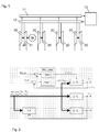
- Fig. 1 shows a charging system for an internal combustion engine 10 with four turbochargers.
- Each of the exhaust gas turbochargers comprises a compressor 20 and an exhaust gas turbine.
- a differentiation is made in the exhaust gas turbines between the conventional exhaust gas turbines 30 and the exhaust gas turbines 31 equipped with adjustable guide geometry.
- a first exhaust gas turbocharger is connected to an electric machine (motor / generator), with which the exhaust gas turbocharger shaft can either be accelerated or braked. When accelerating electrical energy must be expended, during braking, electrical energy can be obtained.
- pneumatic or mechanical drives / outputs can be used. This applies analogously to the other embodiments.
- the same exhaust gas turbocharger is equipped with an exhaust gas turbine 31 with adjustable guide geometry. The remaining turbochargers are equipped without additional equipment (electric machine, adjustable turbine guidance geometry).
- the engine control regulates or controls the power of the electric machine so that either electrical energy is obtained while maintaining a lower limit for the pressure in the air receiver or the exhaust gas turbocharger is driven, so that sets a desired pressure in the air receiver. Due to the intervention of the engine control, the operating point of the exhaust gas turbocharger equipped with the electric machine may be changed inadmissibly.
- the regulation according to the invention uses the regulator 1 according to Fig. 2 a representative of the operating point size of Exhaust gas turbocharger, eg the volume flow ( V ⁇ ref ) or the speed of the turbochargers without additional equipment (2. TL and 3. TL) from, and provides an actuator the position of the turbine vanes (u VTG ) of the exhaust gas turbocharger with electric machine and adjustable turbines -Leitgeometrie (1st TL) so that for this exhaust gas turbocharger the same operating point results as for the other turbochargers without additional equipment.
- a compressor bypass (bypass) with an adjustable valve or flap can be used (u Byp ).
- the desired operating point is predetermined by those exhaust gas turbochargers which are not equipped with adjustable turbine guide geometry.
- the control compensates for disturbances, such as the unknown electrical power of the electrical machine. If at least the temperature (T VA ) is measured after the compressor, a measure of the compressor efficiency can be determined from this.
- T VA temperature
- the compressor efficiency is used to correct the desired operating point so that the control does not unnecessarily shift the operating point of the compressor toward the surge line.
- different geometric dimensions, other thermodynamic parameters and other parameters for the correction of the desired operating point can be used.
- the regulation according to the invention comprises two regulators.
- One of the regulators receives from the control of the internal combustion engine a signal which is representative of a desired operating point, for example the desired pressure in the air receiver (p rec, ref ).
- This controller determines the power of the electric machine (U PTI / PTO ) so that the desired pressure in the air receiver is set.
- Another controller takes over, as described in the first embodiment, the control of the synchronization of the plurality of exhaust gas turbochargers with each other.
- the two controllers can operate independently of each other or be connected in series as a cascade controller, it does not matter which controller represents the outer or inner cascade.
- the controllers are robust enough to carry out, since they will affect each other during operation.
- the two controllers can also be combined in a so-called MIMO controller (multiple input multiple output). In this case, the mutual influence is taken directly into the controller by appropriate design and the stability of the control system is not adversely affected.
- the two controllers can also be reversed so that the desired operating point is adjusted by controlling the adjustable turbine guide.
- the second control affects the performance of the electric machine with the aim of matching the operating conditions of the individual exhaust gas turbochargers with each other by targeted addition / removal of electrical power.
- the representative variable for the operating point to be set can be, in addition to the air receiver pressure, the power of the electrical machine, the areas of the turbine guidance geometry or the purge pressure gradient across the engine.
- the efficiency of the compressor of the individual exhaust gas turbocharger may change differently.
- parallel operated exhaust gas turbochargers with common air receiver has an efficiency reduction on the compressor of an exhaust gas turbocharger an increase in speed and a reduction in the flow rate of the compressor in question.
- a change in the efficiency can be determined.
- the calculated from the measured signals change in the compressor efficiency is used to determine a corrected target operating point of the exhaust gas turbocharger.
- the regulation then takes over the task of preventing the operating point of the compressor concerned from undesirably moving away from its desired operating point.
- the efficiency of the exhaust gas turbocharger for each or each of the exhaust gas turbocharger can be determined. It can then be realized a regulation that adjusts the absolute operating point of the exhaust gas turbocharger, for which purpose, a regulator path is provided per exhaust gas turbocharger.
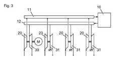
- Fig. 3 shows a second charging system for an internal combustion engine 10, in turn with four exhaust gas turbochargers.
- Each of the exhaust gas turbochargers comprises a compressor 20 and an exhaust gas turbine.
- a first exhaust gas turbocharger is connected to an electric machine.
- the exhaust gas turbine of the exhaust gas turbocharger connected to the electric machine does not have an adjustable guide geometry, but the exhaust gas turbines of all the other exhaust gas turbochargers.
- the operating point of the first exhaust gas turbocharger which is coupled to the electric machine, depending on the engine operating point and Other parameters such as environment, engine or exhaust gas turbocharger pollution, electricity needs of the recipients and electricity production of other producers or power supply depending on the needs of the other recipients and the power of the generators by the output or drive torque of this machine controlled or regulated.
- the turbine surface of the exhaust gas turbines equipped with adjustable guide geometry is reduced or enlarged in such a way that these exhaust gas turbochargers reach a certain operating point.
- the operating point of the remaining exhaust-gas turbochargers can thereby be matched to that of the exhaust-gas turbocharger which is coupled to the electric machine.
- the regulation according to the invention can also be applied to a charging system which consists of two groups of exhaust-gas turbochargers, which are thermodynamically similarly configured in themselves. All turbochargers work in parallel.
- the exhaust gas turbocharger of the first group are equipped with either an electric machine and an adjustable turbine guide or only with one electric machine.
- the exhaust gas turbocharger of the second group are all equipped with an adjustable turbine guide.
- the control can also be applied to charging systems which do not use an electric machine but one or more turbochargers are equipped with adjustable turbine guide.
- one or more turbochargers are equipped with adjustable turbine guide.
- an exhaust gas turbocharger is equipped with an electric machine and adjustable turbine guide device and all other exhaust gas turbochargers only with an adjustable turbine guide device.
- the turbochargers can be of different sizes.
- one of the parallel-operating high-pressure stages can be equipped with an electric machine and adjustable turbine guide device or, as in the first embodiment, a high-pressure stage with one electric machine and all other high-pressure stages are equipped with adjustable turbine guide.
- the control is then applied analogously to the 1-stage charging to the high-pressure stages of the 2-stage charging.
- a charging system register charging is used.
- the turbochargers are typically of different sizes and may be switched on or off individually.
- the control has the task, in particular during transient operating phases, of compensating for the different acceleration behavior of the exhaust gas turbochargers.
Landscapes
- Engineering & Computer Science (AREA)
- Chemical & Material Sciences (AREA)
- Combustion & Propulsion (AREA)
- Mechanical Engineering (AREA)
- General Engineering & Computer Science (AREA)
- Supercharger (AREA)
Abstract
Description
Die Erfindung bezieht sich auf das Gebiet der mittels Abgasturboladern aufgeladenen Brennkraftmaschinen. Sie betrifft die Regelung eines Aufladesystem für eine Brennkraftmaschine mit mehreren Abgasturboladern.The invention relates to the field of supercharged by exhaust gas turbochargers internal combustion engines. It relates to the regulation of a charging system for an internal combustion engine with multiple exhaust gas turbochargers.
Auf grossen 2- oder 4-Takt Motoren können mehrere Abgasturbolader oder Abgasturboladergruppen - also in Serie geschaltete Niederdruck- und Hochdruck-Abgasturbolader, wobei mehrere Niederdruck-Abgasturbolader in einen gemeinsamen Hochdruck-Abgasturbolader fördern oder mehrere Hochdruck-Abgasturbolader von einem Niederdruck-Abgasturbolader gespiesen werden können - im Parallelbetrieb eingesetzt werden. Die Verdichter der mehreren Abgasturbolader fördern die Verdichter Luft in der Regel in einen gemeinsamen LuftreceiverOn large 2- or 4-stroke engines, multiple exhaust gas turbochargers or exhaust gas turbocharger groups - ie series-connected low-pressure and high-pressure turbocharger, with several low-pressure exhaust gas turbochargers in a common high-pressure turbocharger promote or multiple high-pressure turbocharger are fed by a low-pressure exhaust gas turbocharger can - be used in parallel operation. The compressors of the plurality of exhaust gas turbochargers usually convey the compressors air into a common air receiver
Abweichungen in der technischen Ausrüstung, der Baugrösse oder der Performance der einzelnen Abgasturbolader können im stationären oder im transienten Betrieb zu unterschiedlichen Betriebszuständen der Abgasturbolader führen. Die unterschiedlichen Betriebszustände können für einzelne Abgasturbolader zu unzulässigen Belastungen, beispielsweise durch Pumpen oder durch zu hohe Drehzahlen, führen.Deviations in the technical equipment, the size or the performance of the individual exhaust gas turbochargers can lead to different operating states of the exhaust gas turbocharger in stationary or in transient operation. The different operating states can lead to impermissible loads for individual exhaust gas turbochargers, for example due to pumps or due to excessive rotational speeds.
Bei der Aufladung von Brennkraftmaschinen mit mehreren Abgasturboladern oder Abgasturboladergruppen, welche in einen gemeinsamen Luftreceiver fördern kommt es zu Abweichungen der Betriebspunkte der einzelnen Abgasturbolader durch
- a) ungleiche technische Ausrüstung der Abgasturbolader, und die sich daraus ergebenden ungleichen Belastungen
- b) durch ungleiche Spezifikation, Baugrösse der Abgasturbolader,
- c) durch ungleiche Leistungsdaten der Abgasturbolader oder
- d) durch sich aus unterschiedlichen Anbausituationen ergebenden Anströmungs-und Temperaturbedingungen.
- a) unequal technical equipment of the turbocharger, and the resulting uneven loads
- b) due to unequal specification, size of turbocharger,
- c) by unequal performance data of the turbocharger or
- d) due to different cultivation situations resulting flow and temperature conditions.
Um solche ungleiche Betriebszustände der einzelnen Abgasturbolader zu vermeiden, werden heute auf einem Motor in der Regel baugleiche Abgasturbolader eingesetzt.In order to avoid such unequal operating states of the individual exhaust gas turbochargers, turbochargers of the same design are generally used today on an engine.
Um entweder das Teillastverhalten oder das transiente Verhalten des Systems Motor und Abgasturbolader zu verbessern oder eine Energieauskopplung bei Volllast zu ermöglichen, können die Abgasturbolader mit einer elektrischen Maschine, einer Abgasturbine mit variabler Geometrie (VTG), mit einer Verdichterumblasung, mit einem verstellbaren Verdichtervorrad (VCG - variable Verdichtergeometrie) oder mit einer Kombination davon ausgerüstet werden. Bei mehreren parallel arbeitenden Abgasturboladern ist es in bestimmten Anwendungsfällen vorteilhaft, nur einen oder einzelne Abgasturbolader mit den oben erwähnten Zusatzeinrichtungen auszurüsten.In order to improve either the partial load behavior or the transient behavior of the system engine and exhaust gas turbocharger or to enable energy extraction at full load, the exhaust gas turbocharger with an electric machine, a variable geometry exhaust gas turbine (VTG), with a compressor blowing, with an adjustable Verdichtervorrad (VCG variable compressor geometry) or a combination thereof. In the case of several exhaust gas turbochargers operating in parallel, it is advantageous in certain applications to equip only one or a single exhaust gas turbocharger with the abovementioned additional devices.
Die erfindungsgemässe Regelung korrigiert die Abweichungen der Betriebszustände, kompensiert Störungen die von aussen auf einzelne Abgasturbolader einwirken und berücksichtigt die sich durch den Betrieb oder die Anbausituation ergebenden Performanceunterschiede.The regulation according to the invention corrects the deviations of the operating states, compensates for disturbances which act from outside on individual exhaust-gas turbochargers and takes into account the performance differences resulting from the operation or the mounting situation.
Die erfindungsgemässe Regelung erlaubt nun, die Zusatzeinrichtungen so anzusteuern, dass ein unerwünschtes Auseinanderdriften der Betriebspunkte der verschiedenen, parallel zueinander betriebenen Abgasturbolader verhindert wird. Die Regelung soll die Betriebspunkte der einzelnen Abgasturbolader einander annähern oder angleichen, soll Störungen und Leistungsbeeinträchtigungen der Abgasturbolader kompensieren und gegebenenfalls einen erwünschten Betriebspunkt einstellen.The regulation according to the invention now makes it possible to control the additional devices in such a way that an undesired drift apart of the operating points of the various exhaust-gas turbochargers operated in parallel is prevented. The scheme is intended to approximate or equalize the operating points of the individual exhaust gas turbochargers, to compensate for disturbances and performance impairments of the exhaust gas turbocharger and optionally set a desired operating point.
Nachfolgend wird die erfindungsgemässe Regelung anhand von Zeichnungen detailliert erläutert. Hierbei zeigt
- Fig. 1
- ein Aufladesystem mit mehreren Abgasturboladern, wovon einer mit einer elektrischen Maschine verbunden und mit einer verstellbaren Turbinenleitgeometrie ausgestattet ist,
- Fig. 2
- ein Signalflussbild der erfindungsgemässen Regelung, und
- Fig. 3
- ein Aufladesystem mit mehreren Abgasturboladern, wovon einer mit einer elektrischen Maschine verbunden ist und die übrigen mit einer verstellbaren Turbinenleitgeometrie ausgestattet sind.
- Fig. 1
- a turbocharger supercharging system, one of which is connected to an electric machine and equipped with an adjustable turbine geometry,
- Fig. 2
- a signal flow diagram of the inventive control, and
- Fig. 3
- a supercharging system with several turbochargers, one of which is connected to an electric machine and the others are equipped with an adjustable Turbinenleitgeometrie.
Die Motorsteuerung regelt oder steuert die Leistung der elektrischen Maschine so, dass entweder elektrische Energie gewonnen wird unter Einhaltung einer unteren Grenze für den Druck im Luftreceiver oder es wird der Abgasturbolader angetrieben, so dass sich ein gewünschter Druck im Luftreceiver einstellt. Durch die Eingriffe der Motorsteuerung wird der Betriebspunkt des mit der elektrischen Maschine ausgestatteten Abgasturboladers möglicherweise unzulässig verändert.The engine control regulates or controls the power of the electric machine so that either electrical energy is obtained while maintaining a lower limit for the pressure in the air receiver or the exhaust gas turbocharger is driven, so that sets a desired pressure in the air receiver. Due to the intervention of the engine control, the operating point of the exhaust gas turbocharger equipped with the electric machine may be changed inadmissibly.
In einer ersten Ausführungsform greift die erfindungsgemässe Regelung mit dem Regler 1 gemäss
In einer zweiten Ausführungsform umfasst die erfindungsgemässe Regelung zwei Regler. Einer der Regler (Regler 2) erhält von der Steuerung der Brennkraftmaschine ein Signal, das repräsentativ für einen erwünschten Betriebspunkt ist, beispielsweise der erwünschte Druck im Luftreceiver (prec,ref). Dieser Regler bestimmt die Leistung der elektrischen Maschine (UPTI/PTO) so, dass sich der erwünschte Druck im Luftreceiver einstellt. Ein weiterer Regler (Regler 1) übernimmt, wie in der ersten Ausführungsform beschrieben, die Regelung des Gleichlaufs der mehreren Abgasturbolader untereinander. Die zwei Regler können unabhängig voneinander operieren oder als Kaskadenregler hintereinander geschaltet werden, wobei gleichgültig ist, welcher Regler die äusser bzw. innere Kaskade darstellt. Die Regler sind genügend robust auszuführen, da sie sich im Betrieb gegenseitig beeinflussen werden. Optional könne die beiden Regler auch in einem sogenannten MIMO-Regler (multiple input multiple output) vereint werden. Dabei wird die gegenseitige Beeinflussung direkt im Regler durch geeignete Auslegung berücksichtigt und die Stabilität des Regelsystems wird nicht nachteilig beeinflusst.In a second embodiment, the regulation according to the invention comprises two regulators. One of the regulators (controller 2) receives from the control of the internal combustion engine a signal which is representative of a desired operating point, for example the desired pressure in the air receiver (p rec, ref ). This controller determines the power of the electric machine (U PTI / PTO ) so that the desired pressure in the air receiver is set. Another controller (controller 1) takes over, as described in the first embodiment, the control of the synchronization of the plurality of exhaust gas turbochargers with each other. The two controllers can operate independently of each other or be connected in series as a cascade controller, it does not matter which controller represents the outer or inner cascade. The controllers are robust enough to carry out, since they will affect each other during operation. Optionally, the two controllers can also be combined in a so-called MIMO controller (multiple input multiple output). In this case, the mutual influence is taken directly into the controller by appropriate design and the stability of the control system is not adversely affected.
Die beiden Regler können auch derart vertauscht werden, dass der erwünschte Betriebspunkt durch Regelung der verstellbaren Turbinen-Leitvorrichtung eingestellt wird. Die zweite Regelung wirkt auf die Leistung der elektrischen Maschine mit dem Ziel, durch gezielte Zugabe/ Entnahme von elektrischer Leistung die Betriebszustände der einzelnen Abgasturbolader untereinander anzugleichen.The two controllers can also be reversed so that the desired operating point is adjusted by controlling the adjustable turbine guide. The second control affects the performance of the electric machine with the aim of matching the operating conditions of the individual exhaust gas turbochargers with each other by targeted addition / removal of electrical power.
Die repräsentative Grösse für den einzustellenden Betriebspunkt kann ausser dem Luftreceiverdruck auch die Leistung der elektrischen Maschine, die Flächen der Turbinen-Leitgeometrie oder das Spüldruckgefälle über dem Motor sein.The representative variable for the operating point to be set can be, in addition to the air receiver pressure, the power of the electrical machine, the areas of the turbine guidance geometry or the purge pressure gradient across the engine.
Im Laufe des Betriebes kann sich der Wirkungsgrad der Verdichter der einzelnen Abgasturbolader unterschiedlich ändern. Bei parallel betriebenen Abgasturboladern mit gemeinsamem Luftreceiver hat eine Wirkungsgradabsenkung am Verdichter eines Abgasturboladers eine Erhöhung der Drehzahl und eine Absenkung des Volumenstromes des betreffenden Verdichters zur Folge. Durch Messung der Temperaturen jeweils nach dem Verdichter (und optional weiterer Grössen) kann eine Änderung des Wirkungsgrades festgestellt werden. Die aus den Messsignalen berechnete Änderung des Verdichterwirkungsgrades dient dazu, einen korrigierten Soll-Betriebspunkt des Abgasturboladers zu bestimmen. Die Regelung übernimmt dann die Aufgabe, zu verhindern, dass der Betriebspunkt des betroffenen Verdichters sich in unerwünschter Weise von seinem Soll-Betriebspunkt entfernt.In the course of operation, the efficiency of the compressor of the individual exhaust gas turbocharger may change differently. In parallel operated exhaust gas turbochargers with common air receiver has an efficiency reduction on the compressor of an exhaust gas turbocharger an increase in speed and a reduction in the flow rate of the compressor in question. By measuring the temperatures after the compressor (and optionally further sizes), a change in the efficiency can be determined. The calculated from the measured signals change in the compressor efficiency is used to determine a corrected target operating point of the exhaust gas turbocharger. The regulation then takes over the task of preventing the operating point of the compressor concerned from undesirably moving away from its desired operating point.
Bei einer geeigneten Auswahl von Messgrössen kann der Wirkungsgrad der Abgasturbolader für jeden oder einzelne der Abgasturbolader bestimmt werden. Es kann dann eine Regelung realisiert werden, die den absoluten Betriebspunkt der Abgasturbolader einstellt, wobei hierfür pro Abgasturbolader ein Reglerpfad vorzusehen ist.With a suitable selection of measured variables, the efficiency of the exhaust gas turbocharger for each or each of the exhaust gas turbocharger can be determined. It can then be realized a regulation that adjusts the absolute operating point of the exhaust gas turbocharger, for which purpose, a regulator path is provided per exhaust gas turbocharger.
Der Betriebspunkt des ersten Abgasturboladers, welcher an die elektrische Maschine gekuppelt ist, kann in Abhängigkeit des Verbrennungsmotorbetriebspunktes und weiterer Parameter wie Umwelt, Motor- oder Abgasturbolader-Verschmutzung, Strombedarf der Bezüger und Stromproduktion anderer Erzeuger oder Stromzufuhr in Abhängigkeit des Bedarfs der übrigen Bezüger und der Leistung der Erzeuger durch das Abtriebs- oder Antriebsmoment dieser Maschine gesteuert respektive geregelt werden.The operating point of the first exhaust gas turbocharger, which is coupled to the electric machine, depending on the engine operating point and Other parameters such as environment, engine or exhaust gas turbocharger pollution, electricity needs of the recipients and electricity production of other producers or power supply depending on the needs of the other recipients and the power of the generators by the output or drive torque of this machine controlled or regulated.
Damit die übrigen, an keine elektrische Maschine gekuppelten Abgasturbolader im gewünschten Betriebspunkt laufen, wird die Turbinenfläche der mit verstellbarer Leitgeometrie ausgerüsteten Abgasturbinen so verkleinert oder vergrössert, dass diese Abgasturbolader einen bestimmten Betriebspunkt erreichen. Optional kann dadurch der Betriebspunkt der übrigen Abgasturbolader demjenigen des Abgasturboladers, welcher mit der elektrischen Maschine gekuppelt ist, angeglichen werden. Als Alternative ist es auch möglich, die Turbinenfläche in Abhängigkeit des Betriebspunktes des Verbrennungsmotors etc. vorzugeben und den Abgasturbolader, welcher an eine elektrische Maschine gekoppelt ist, über das Abtriebs- oder Antriebsmoment dieser Maschine zu steuern respektive zu regeln.So that the remaining exhaust gas turbochargers coupled to no electric machine run at the desired operating point, the turbine surface of the exhaust gas turbines equipped with adjustable guide geometry is reduced or enlarged in such a way that these exhaust gas turbochargers reach a certain operating point. Optionally, the operating point of the remaining exhaust-gas turbochargers can thereby be matched to that of the exhaust-gas turbocharger which is coupled to the electric machine. As an alternative, it is also possible to specify the turbine surface as a function of the operating point of the internal combustion engine, etc., and to control the exhaust-gas turbocharger, which is coupled to an electrical machine, via the output or drive torque of this machine.
Die erfindungsgemässe Regelung kann auch auf Aufladesystem angewandt werden, welche aus zwei Gruppen von in sich thermodynamisch ähnlich konfigurierten Abgasturboladern besteht. Alle Abgasturbolader arbeiten parallel. Die Abgasturbolader der ersten Gruppe sind entweder mit je einer elektrischen Maschine und einer verstellbaren Turbinen-Leitvorrichtung oder aber nur mit je einer elektrischen Maschine ausgerüstet. Im zweiten Falle sind die Abgasturbolader der zweiten Gruppe alle je mit einer verstellbaren Turbinen-Leitvorrichtung ausgerüstet.The regulation according to the invention can also be applied to a charging system which consists of two groups of exhaust-gas turbochargers, which are thermodynamically similarly configured in themselves. All turbochargers work in parallel. The exhaust gas turbocharger of the first group are equipped with either an electric machine and an adjustable turbine guide or only with one electric machine. In the second case, the exhaust gas turbocharger of the second group are all equipped with an adjustable turbine guide.
Die Regelung kann auch auf Aufladesysteme angewendet werden, welche keine elektrische Maschine einsetzen aber ein oder mehrere Abgasturbolader mit verstellbarer Turbinen-Leitvorrichtung ausgerüstet sind. Ebenso ist der Fall einzubeziehen, wo ein Abgasturbolader mit elektrischer Maschine und verstellbarer Turbinen-Leitvorrichtung ausgerüstet ist und alle andern Abgasturbolader nur mit verstellbarer Turbinen-Leitvorrichtung. Die Abgasturbolader können von verschiedener Grösse sein.The control can also be applied to charging systems which do not use an electric machine but one or more turbochargers are equipped with adjustable turbine guide. Likewise, the case is to be considered where an exhaust gas turbocharger is equipped with an electric machine and adjustable turbine guide device and all other exhaust gas turbochargers only with an adjustable turbine guide device. The turbochargers can be of different sizes.
Bei der 2-stufigen Aufladung kann eine der parallel arbeitenden Hochdruckstufen mit einer elektrischen Maschine und verstellbarer Turbinen-Leitvorrichtung ausgestattet werden oder wie in der ersten Ausführungsform eine Hochdruckstufe mit einer elektrischen Maschine und alle andern Hochdruckstufen mit verstellbarer Turbinen-Leitvorrichtung ausgerüstet werden. Die Regelung wird dann analog der 1-stufigen Aufladung auf die Hochdruckstufen der 2-stufigen Aufladung angewendet.In the case of 2-stage charging, one of the parallel-operating high-pressure stages can be equipped with an electric machine and adjustable turbine guide device or, as in the first embodiment, a high-pressure stage with one electric machine and all other high-pressure stages are equipped with adjustable turbine guide. The control is then applied analogously to the 1-stage charging to the high-pressure stages of the 2-stage charging.
In einer weiteren Ausführungsform wird ein Aufladesystem Registeraufladung eingesetzt. In diesem Fall sind die Abgasturbolader typischerweise von unterschiedlicher Grösse und können einzeln zu oder weggeschaltet werden. Die Regelung hat insbesondere während transienten Betriebsphasen die Aufgabe, das unterschiedliche Beschleunigungsverhalten der Abgasturbolader zu kompensieren.In a further embodiment, a charging system register charging is used. In this case, the turbochargers are typically of different sizes and may be switched on or off individually. The control has the task, in particular during transient operating phases, of compensating for the different acceleration behavior of the exhaust gas turbochargers.
- 1010
- BrennkraftmaschineInternal combustion engine
- 1111
- Luftreceiverair receiver
- 1212
- Abgasreceiverexhaust receiver
- 2020
- Verdichtercompressor
- 3030
- Turbineturbine
- 3131
- Turbine mit verstellbarer LeitgeometrieTurbine with adjustable guide geometry
- MM
- Elektrische Maschine (Motor/Generator)Electric machine (motor / generator)
Claims (3)
Priority Applications (5)
| Application Number | Priority Date | Filing Date | Title |
|---|---|---|---|
| EP07110902A EP2006507A1 (en) | 2007-06-22 | 2007-06-22 | Control of a charging system for combustion engines |
| JP2010512715A JP5080643B2 (en) | 2007-06-22 | 2008-06-23 | Control device for supercharger system for internal combustion machine |
| KR1020107001075A KR101197065B1 (en) | 2007-06-22 | 2008-06-23 | Regulation of a supercharging system for internal combustion engines |
| EP08774223A EP2171236A1 (en) | 2007-06-22 | 2008-06-23 | Regulation of a supercharging system for internal combusiton engines |
| PCT/EP2008/057957 WO2009000807A1 (en) | 2007-06-22 | 2008-06-23 | Regulation of a supercharging system for internal combusiton engines |
Applications Claiming Priority (1)
| Application Number | Priority Date | Filing Date | Title |
|---|---|---|---|
| EP07110902A EP2006507A1 (en) | 2007-06-22 | 2007-06-22 | Control of a charging system for combustion engines |
Publications (1)
| Publication Number | Publication Date |
|---|---|
| EP2006507A1 true EP2006507A1 (en) | 2008-12-24 |
Family
ID=38697523
Family Applications (2)
| Application Number | Title | Priority Date | Filing Date |
|---|---|---|---|
| EP07110902A Withdrawn EP2006507A1 (en) | 2007-06-22 | 2007-06-22 | Control of a charging system for combustion engines |
| EP08774223A Withdrawn EP2171236A1 (en) | 2007-06-22 | 2008-06-23 | Regulation of a supercharging system for internal combusiton engines |
Family Applications After (1)
| Application Number | Title | Priority Date | Filing Date |
|---|---|---|---|
| EP08774223A Withdrawn EP2171236A1 (en) | 2007-06-22 | 2008-06-23 | Regulation of a supercharging system for internal combusiton engines |
Country Status (4)
| Country | Link |
|---|---|
| EP (2) | EP2006507A1 (en) |
| JP (1) | JP5080643B2 (en) |
| KR (1) | KR101197065B1 (en) |
| WO (1) | WO2009000807A1 (en) |
Cited By (3)
| Publication number | Priority date | Publication date | Assignee | Title |
|---|---|---|---|---|
| EP2463496A1 (en) * | 2010-12-10 | 2012-06-13 | Perkins Engines Company Limited | Multiple turbocharger control |
| WO2012113425A1 (en) * | 2011-02-26 | 2012-08-30 | Daimler Ag | Exhaust-gas turbocharger arrangement |
| EP3228841A4 (en) * | 2015-01-30 | 2018-06-06 | Mitsubishi Heavy Industries, Ltd. | Supercharging system, control device for supercharging system, and method for operating supercharging system |
Citations (9)
| Publication number | Priority date | Publication date | Assignee | Title |
|---|---|---|---|---|
| GB267149A (en) * | 1926-03-08 | 1927-08-18 | Alfred Buchi | Improvements in means for supplying the charge in internal combustion engines |
| GB1261335A (en) * | 1969-04-16 | 1972-01-26 | Tzadok Zakon | Improvement in supercharged two stroke diesel engines |
| DE2609389A1 (en) * | 1976-03-06 | 1977-09-08 | Maschf Augsburg Nuernberg Ag | EXHAUST GAS TURBOCHARGER UNIT |
| DE19827627A1 (en) * | 1998-06-20 | 1999-12-23 | Daimler Chrysler Ag | Procedure for controlling turbocharged IC engine which has two banks of cylinders |
| EP1336737A2 (en) * | 2002-02-18 | 2003-08-20 | Toyota Jidosha Kabushiki Kaisha | Supercharge pressure control apparatus and method |
| DE10224686A1 (en) * | 2002-06-04 | 2003-12-18 | Bosch Gmbh Robert | Charging pressure regulation method for IC engine turbochargers, uses cascade regulation device for providing 2-stage regulation |
| EP1498594A1 (en) * | 2003-07-16 | 2005-01-19 | Toyota Jidosha Kabushiki Kaisha | Exhaust control apparatus of internal combustion engine and exhaust gas flow amount estimating method |
| WO2005059317A1 (en) * | 2003-12-10 | 2005-06-30 | Honeywell International Inc. | Variable nozzle device for a turbocharger |
| WO2007020524A1 (en) * | 2005-08-19 | 2007-02-22 | Toyota Jidosha Kabushiki Kaisha | Boost pressure control |
Family Cites Families (9)
| Publication number | Priority date | Publication date | Assignee | Title |
|---|---|---|---|---|
| JPH03267525A (en) * | 1990-03-19 | 1991-11-28 | Toyota Motor Corp | Engine with supercharger |
| JP2884725B2 (en) * | 1990-06-21 | 1999-04-19 | いすゞ自動車株式会社 | Control device for twin turbocharger |
| DE4416572C1 (en) * | 1994-05-11 | 1995-04-27 | Daimler Benz Ag | Turbocharged internal combustion engine |
| US6550247B1 (en) * | 2001-08-30 | 2003-04-22 | Caterpillar Inc | Multiple parallel turbocharger control with discrete step nozzles |
| DE10235701B3 (en) * | 2002-08-03 | 2004-04-15 | UDO MAILäNDER GMBH | Supercharged internal combustion engine |
| JP4483278B2 (en) * | 2003-12-04 | 2010-06-16 | トヨタ自動車株式会社 | Internal combustion engine with multiple turbochargers |
| JP4438521B2 (en) * | 2004-06-03 | 2010-03-24 | トヨタ自動車株式会社 | Multi-cylinder internal combustion engine with multiple turbochargers |
| JP2006097542A (en) * | 2004-09-29 | 2006-04-13 | Nissan Motor Co Ltd | Supercharging pressure regulating device of variable supercharging system |
| US7571608B2 (en) | 2005-11-28 | 2009-08-11 | General Electric Company | Turbocharged engine system and method of operation |
-
2007
- 2007-06-22 EP EP07110902A patent/EP2006507A1/en not_active Withdrawn
-
2008
- 2008-06-23 WO PCT/EP2008/057957 patent/WO2009000807A1/en active Application Filing
- 2008-06-23 KR KR1020107001075A patent/KR101197065B1/en not_active IP Right Cessation
- 2008-06-23 JP JP2010512715A patent/JP5080643B2/en not_active Expired - Fee Related
- 2008-06-23 EP EP08774223A patent/EP2171236A1/en not_active Withdrawn
Patent Citations (9)
| Publication number | Priority date | Publication date | Assignee | Title |
|---|---|---|---|---|
| GB267149A (en) * | 1926-03-08 | 1927-08-18 | Alfred Buchi | Improvements in means for supplying the charge in internal combustion engines |
| GB1261335A (en) * | 1969-04-16 | 1972-01-26 | Tzadok Zakon | Improvement in supercharged two stroke diesel engines |
| DE2609389A1 (en) * | 1976-03-06 | 1977-09-08 | Maschf Augsburg Nuernberg Ag | EXHAUST GAS TURBOCHARGER UNIT |
| DE19827627A1 (en) * | 1998-06-20 | 1999-12-23 | Daimler Chrysler Ag | Procedure for controlling turbocharged IC engine which has two banks of cylinders |
| EP1336737A2 (en) * | 2002-02-18 | 2003-08-20 | Toyota Jidosha Kabushiki Kaisha | Supercharge pressure control apparatus and method |
| DE10224686A1 (en) * | 2002-06-04 | 2003-12-18 | Bosch Gmbh Robert | Charging pressure regulation method for IC engine turbochargers, uses cascade regulation device for providing 2-stage regulation |
| EP1498594A1 (en) * | 2003-07-16 | 2005-01-19 | Toyota Jidosha Kabushiki Kaisha | Exhaust control apparatus of internal combustion engine and exhaust gas flow amount estimating method |
| WO2005059317A1 (en) * | 2003-12-10 | 2005-06-30 | Honeywell International Inc. | Variable nozzle device for a turbocharger |
| WO2007020524A1 (en) * | 2005-08-19 | 2007-02-22 | Toyota Jidosha Kabushiki Kaisha | Boost pressure control |
Cited By (6)
| Publication number | Priority date | Publication date | Assignee | Title |
|---|---|---|---|---|
| EP2463496A1 (en) * | 2010-12-10 | 2012-06-13 | Perkins Engines Company Limited | Multiple turbocharger control |
| WO2012076726A1 (en) * | 2010-12-10 | 2012-06-14 | Perkins Engine Company Limited | Multiple turbocharger control |
| US9726187B2 (en) | 2010-12-10 | 2017-08-08 | Perkins Engines Company Limited | Multiple turbocharger control |
| WO2012113425A1 (en) * | 2011-02-26 | 2012-08-30 | Daimler Ag | Exhaust-gas turbocharger arrangement |
| EP3228841A4 (en) * | 2015-01-30 | 2018-06-06 | Mitsubishi Heavy Industries, Ltd. | Supercharging system, control device for supercharging system, and method for operating supercharging system |
| US10753272B2 (en) | 2015-01-30 | 2020-08-25 | Mitsubishi Heavy Industries, Ltd. | Engine supercharger for maintaining a battery charge |
Also Published As
| Publication number | Publication date |
|---|---|
| JP2010530937A (en) | 2010-09-16 |
| WO2009000807A1 (en) | 2008-12-31 |
| KR20100022112A (en) | 2010-02-26 |
| EP2171236A1 (en) | 2010-04-07 |
| KR101197065B1 (en) | 2012-11-06 |
| JP5080643B2 (en) | 2012-11-21 |
Similar Documents
| Publication | Publication Date | Title |
|---|---|---|
| DE102010016708B4 (en) | Procedures related to the control and operation of a gas turbine | |
| EP2394041B1 (en) | Internal combustion engine | |
| WO2002004799A1 (en) | Method for controlling a charge pressure in an internal combustion engine with an exhaust-gas turbocharger | |
| WO2012097389A2 (en) | Method for operating an internal combustion engine having at least two cylinders | |
| DE102008044470A1 (en) | Turbine plant with modulated combustion and afterburning chamber | |
| DE3040139A1 (en) | CONTROL SYSTEM FOR A GAS TURBINE | |
| DE60114979T2 (en) | Control system for a turbocharger of variable geometry | |
| EP3722573A1 (en) | Method for operating a combustion engine with an exhaust gas turbocharger and an electrically driven compressor and devices thereof | |
| EP2006507A1 (en) | Control of a charging system for combustion engines | |
| WO2020164948A1 (en) | Method for operating a turbocharger | |
| WO2009000804A2 (en) | Exhaust-driven turbocharger | |
| DE102009042283A1 (en) | Turbocompound system and components | |
| DE102012019896A1 (en) | Internal combustion engine for motor vehicles, particularly passenger cars, has cylinder arrangement, air supply passage, exhaust passage and turbo charger with compressor arranged in air supply passage | |
| EP2006514B1 (en) | Stationary combustion engine | |
| AT516613B1 (en) | METHOD FOR OPERATING AN INTERNAL COMBUSTION ENGINE | |
| EP2037099B1 (en) | Combustion machines and motor regulating device | |
| EP3097293A1 (en) | Variable limit-value power control for gas turbines | |
| DE102019216576A1 (en) | Method for operating an internal combustion engine and internal combustion engine for carrying out such a method | |
| WO2018059810A1 (en) | Method for operating a bi-turbo system, and engine control unit | |
| EP3071818B1 (en) | Operation of a gas turbine plant with a compressor and a turbine | |
| DE102015014810B4 (en) | Method for operating a drive device for a motor vehicle and corresponding drive device | |
| EP2963265A1 (en) | Method and control for operating an exhaust gas turbocharger | |
| WO2009056636A1 (en) | Regulation of an exhaust-gas turbocharger | |
| WO2023161065A1 (en) | Control device for an internal combustion engine, internal combustion engine assembly comprising an internal combustion engine and a control device of this type, method for operating an internal combustion engine, and method for determining a component characteristic map | |
| DE102011108766A1 (en) | Method for changing rotational speed of turbo gas engine from speed to another speed, involves detecting operating parameters, and adjusting fuel stream supplied to turbo gas engine in dependence on detected operating parameters |
Legal Events
| Date | Code | Title | Description |
|---|---|---|---|
| PUAI | Public reference made under article 153(3) epc to a published international application that has entered the european phase |
Free format text: ORIGINAL CODE: 0009012 |
|
| AK | Designated contracting states |
Kind code of ref document: A1 Designated state(s): AT BE BG CH CY CZ DE DK EE ES FI FR GB GR HU IE IS IT LI LT LU LV MC MT NL PL PT RO SE SI SK TR |
|
| AX | Request for extension of the european patent |
Extension state: AL BA HR MK RS |
|
| AKX | Designation fees paid | ||
| REG | Reference to a national code |
Ref country code: DE Ref legal event code: 8566 |
|
| STAA | Information on the status of an ep patent application or granted ep patent |
Free format text: STATUS: THE APPLICATION IS DEEMED TO BE WITHDRAWN |
|
| 18D | Application deemed to be withdrawn |
Effective date: 20090625 |