EP2006480A1 - Damper for furniture - Google Patents
Damper for furniture Download PDFInfo
- Publication number
- EP2006480A1 EP2006480A1 EP08164908A EP08164908A EP2006480A1 EP 2006480 A1 EP2006480 A1 EP 2006480A1 EP 08164908 A EP08164908 A EP 08164908A EP 08164908 A EP08164908 A EP 08164908A EP 2006480 A1 EP2006480 A1 EP 2006480A1
- Authority
- EP
- European Patent Office
- Prior art keywords
- piston
- piston rod
- damper
- housing
- plate
- Prior art date
- Legal status (The legal status is an assumption and is not a legal conclusion. Google has not performed a legal analysis and makes no representation as to the accuracy of the status listed.)
- Granted
Links
- 238000013016 damping Methods 0.000 claims abstract description 22
- 239000012530 fluid Substances 0.000 claims abstract description 21
- 238000007789 sealing Methods 0.000 description 20
- 239000006260 foam Substances 0.000 description 9
- 239000004033 plastic Substances 0.000 description 4
- 238000010276 construction Methods 0.000 description 2
- 238000005553 drilling Methods 0.000 description 2
- 230000000694 effects Effects 0.000 description 2
- 238000004519 manufacturing process Methods 0.000 description 2
- 239000000463 material Substances 0.000 description 2
- 239000002184 metal Substances 0.000 description 2
- 239000002245 particle Substances 0.000 description 2
- 239000002985 plastic film Substances 0.000 description 2
- 229920006255 plastic film Polymers 0.000 description 2
- 238000004026 adhesive bonding Methods 0.000 description 1
- 230000002411 adverse Effects 0.000 description 1
- 238000005452 bending Methods 0.000 description 1
- 230000009286 beneficial effect Effects 0.000 description 1
- 230000015572 biosynthetic process Effects 0.000 description 1
- 230000006835 compression Effects 0.000 description 1
- 238000007906 compression Methods 0.000 description 1
- 238000011109 contamination Methods 0.000 description 1
- 230000003247 decreasing effect Effects 0.000 description 1
- 238000006073 displacement reaction Methods 0.000 description 1
- 238000004049 embossing Methods 0.000 description 1
- 238000000605 extraction Methods 0.000 description 1
- 239000012535 impurity Substances 0.000 description 1
- 238000002347 injection Methods 0.000 description 1
- 239000007924 injection Substances 0.000 description 1
- 238000001746 injection moulding Methods 0.000 description 1
- 238000005304 joining Methods 0.000 description 1
- 238000003754 machining Methods 0.000 description 1
- 230000007246 mechanism Effects 0.000 description 1
- 238000000034 method Methods 0.000 description 1
- 229920002545 silicone oil Polymers 0.000 description 1
- 238000003466 welding Methods 0.000 description 1
Images


Classifications
-
- E—FIXED CONSTRUCTIONS
- E05—LOCKS; KEYS; WINDOW OR DOOR FITTINGS; SAFES
- E05F—DEVICES FOR MOVING WINGS INTO OPEN OR CLOSED POSITION; CHECKS FOR WINGS; WING FITTINGS NOT OTHERWISE PROVIDED FOR, CONCERNED WITH THE FUNCTIONING OF THE WING
- E05F5/00—Braking devices, e.g. checks; Stops; Buffers
- E05F5/06—Buffers or stops limiting opening of swinging wings, e.g. floor or wall stops
- E05F5/10—Buffers or stops limiting opening of swinging wings, e.g. floor or wall stops with piston brakes
-
- E—FIXED CONSTRUCTIONS
- E05—LOCKS; KEYS; WINDOW OR DOOR FITTINGS; SAFES
- E05F—DEVICES FOR MOVING WINGS INTO OPEN OR CLOSED POSITION; CHECKS FOR WINGS; WING FITTINGS NOT OTHERWISE PROVIDED FOR, CONCERNED WITH THE FUNCTIONING OF THE WING
- E05F5/00—Braking devices, e.g. checks; Stops; Buffers
- E05F5/02—Braking devices, e.g. checks; Stops; Buffers specially for preventing the slamming of swinging wings during final closing movement, e.g. jamb stops
-
- F—MECHANICAL ENGINEERING; LIGHTING; HEATING; WEAPONS; BLASTING
- F16—ENGINEERING ELEMENTS AND UNITS; GENERAL MEASURES FOR PRODUCING AND MAINTAINING EFFECTIVE FUNCTIONING OF MACHINES OR INSTALLATIONS; THERMAL INSULATION IN GENERAL
- F16F—SPRINGS; SHOCK-ABSORBERS; MEANS FOR DAMPING VIBRATION
- F16F9/00—Springs, vibration-dampers, shock-absorbers, or similarly-constructed movement-dampers using a fluid or the equivalent as damping medium
- F16F9/003—Dampers characterised by having pressure absorbing means other than gas, e.g. sponge rubber
-
- F—MECHANICAL ENGINEERING; LIGHTING; HEATING; WEAPONS; BLASTING
- F16—ENGINEERING ELEMENTS AND UNITS; GENERAL MEASURES FOR PRODUCING AND MAINTAINING EFFECTIVE FUNCTIONING OF MACHINES OR INSTALLATIONS; THERMAL INSULATION IN GENERAL
- F16F—SPRINGS; SHOCK-ABSORBERS; MEANS FOR DAMPING VIBRATION
- F16F9/00—Springs, vibration-dampers, shock-absorbers, or similarly-constructed movement-dampers using a fluid or the equivalent as damping medium
- F16F9/32—Details
- F16F9/50—Special means providing automatic damping adjustment, i.e. self-adjustment of damping by particular sliding movements of a valve element, other than flexions or displacement of valve discs; Special means providing self-adjustment of spring characteristics
- F16F9/516—Special means providing automatic damping adjustment, i.e. self-adjustment of damping by particular sliding movements of a valve element, other than flexions or displacement of valve discs; Special means providing self-adjustment of spring characteristics resulting in the damping effects during contraction being different from the damping effects during extension, i.e. responsive to the direction of movement
-
- E—FIXED CONSTRUCTIONS
- E05—LOCKS; KEYS; WINDOW OR DOOR FITTINGS; SAFES
- E05F—DEVICES FOR MOVING WINGS INTO OPEN OR CLOSED POSITION; CHECKS FOR WINGS; WING FITTINGS NOT OTHERWISE PROVIDED FOR, CONCERNED WITH THE FUNCTIONING OF THE WING
- E05F5/00—Braking devices, e.g. checks; Stops; Buffers
- E05F5/006—Braking devices, e.g. checks; Stops; Buffers for hinges having a cup-shaped fixing part, e.g. for attachment to cabinets or furniture
-
- E—FIXED CONSTRUCTIONS
- E05—LOCKS; KEYS; WINDOW OR DOOR FITTINGS; SAFES
- E05Y—INDEXING SCHEME RELATING TO HINGES OR OTHER SUSPENSION DEVICES FOR DOORS, WINDOWS OR WINGS AND DEVICES FOR MOVING WINGS INTO OPEN OR CLOSED POSITION, CHECKS FOR WINGS AND WING FITTINGS NOT OTHERWISE PROVIDED FOR, CONCERNED WITH THE FUNCTIONING OF THE WING
- E05Y2201/00—Constructional elements; Accessories therefore
- E05Y2201/20—Brakes; Disengaging means, e.g. clutches; Holders, e.g. locks; Stops; Accessories therefore
- E05Y2201/21—Brakes
-
- E—FIXED CONSTRUCTIONS
- E05—LOCKS; KEYS; WINDOW OR DOOR FITTINGS; SAFES
- E05Y—INDEXING SCHEME RELATING TO HINGES OR OTHER SUSPENSION DEVICES FOR DOORS, WINDOWS OR WINGS AND DEVICES FOR MOVING WINGS INTO OPEN OR CLOSED POSITION, CHECKS FOR WINGS AND WING FITTINGS NOT OTHERWISE PROVIDED FOR, CONCERNED WITH THE FUNCTIONING OF THE WING
- E05Y2201/00—Constructional elements; Accessories therefore
- E05Y2201/20—Brakes; Disengaging means, e.g. clutches; Holders, e.g. locks; Stops; Accessories therefore
- E05Y2201/252—Brakes; Disengaging means, e.g. clutches; Holders, e.g. locks; Stops; Accessories therefore characterised by type of friction
- E05Y2201/254—Fluid or viscous friction
- E05Y2201/256—Fluid or viscous friction with pistons or vanes
-
- E—FIXED CONSTRUCTIONS
- E05—LOCKS; KEYS; WINDOW OR DOOR FITTINGS; SAFES
- E05Y—INDEXING SCHEME RELATING TO HINGES OR OTHER SUSPENSION DEVICES FOR DOORS, WINDOWS OR WINGS AND DEVICES FOR MOVING WINGS INTO OPEN OR CLOSED POSITION, CHECKS FOR WINGS AND WING FITTINGS NOT OTHERWISE PROVIDED FOR, CONCERNED WITH THE FUNCTIONING OF THE WING
- E05Y2201/00—Constructional elements; Accessories therefore
- E05Y2201/20—Brakes; Disengaging means, e.g. clutches; Holders, e.g. locks; Stops; Accessories therefore
- E05Y2201/262—Brakes; Disengaging means, e.g. clutches; Holders, e.g. locks; Stops; Accessories therefore characterised by type of motion
- E05Y2201/264—Brakes; Disengaging means, e.g. clutches; Holders, e.g. locks; Stops; Accessories therefore characterised by type of motion linear
-
- E—FIXED CONSTRUCTIONS
- E05—LOCKS; KEYS; WINDOW OR DOOR FITTINGS; SAFES
- E05Y—INDEXING SCHEME RELATING TO HINGES OR OTHER SUSPENSION DEVICES FOR DOORS, WINDOWS OR WINGS AND DEVICES FOR MOVING WINGS INTO OPEN OR CLOSED POSITION, CHECKS FOR WINGS AND WING FITTINGS NOT OTHERWISE PROVIDED FOR, CONCERNED WITH THE FUNCTIONING OF THE WING
- E05Y2600/00—Mounting or coupling arrangements for elements provided for in this subclass
- E05Y2600/50—Mounting methods; Positioning
- E05Y2600/52—Toolless
- E05Y2600/53—Snapping
-
- E—FIXED CONSTRUCTIONS
- E05—LOCKS; KEYS; WINDOW OR DOOR FITTINGS; SAFES
- E05Y—INDEXING SCHEME RELATING TO HINGES OR OTHER SUSPENSION DEVICES FOR DOORS, WINDOWS OR WINGS AND DEVICES FOR MOVING WINGS INTO OPEN OR CLOSED POSITION, CHECKS FOR WINGS AND WING FITTINGS NOT OTHERWISE PROVIDED FOR, CONCERNED WITH THE FUNCTIONING OF THE WING
- E05Y2900/00—Application of doors, windows, wings or fittings thereof
- E05Y2900/20—Application of doors, windows, wings or fittings thereof for furnitures, e.g. cabinets
Definitions
- the present invention relates to a damper for furniture, in particular for hinges, comprising a housing in which a piston connected to a piston rod is slidably received, wherein a fluid flows during a movement of the piston within the housing through a flow channel on or in the piston upon movement of the piston in different directions a different damping force is obtained.
- dampers are known in which the fluid flows through an annular gap between the piston and the housing wall.
- the smallest deviations in the diameter of the piston or in the inner diameter of the cylinder have a major effect on the damping behavior.
- Tolerances can add up and, in particular, the housing wall can bend when the internal pressure changes and increase the annular gap.
- impurities can also adversely affect the damping behavior here.
- the damper is designed as a pressure damper, can be provided on the piston rod and / or the housing locking means, preferably with bendable legs, for connection to another component, since the tensile loads during the movement of the piston rod are smaller than the holding forces of the locking means, so that the damper can be easily and quickly mounted and retrofitted.
- the cross section of the flow channel is partially variable by the piston is movable relative to a plate, wherein the plate and / or the piston has radially extending grooves which form at least part of the flow channel.
- the cross-section of the flow channel can be set relatively precisely, with the plate mounted on the piston being easy to produce is and can be replaced if necessary.
- the damper can be easily adjusted to the particular application, since the damping force depends mainly on the design of the flow channel on or in the piston, in particular the flow cross-section of the radial grooves, which not only form a diaphragm, but of the fluid over a certain Flowed through the route.
- This distance of the radial groove can be completely used to generate frictional forces and thus a pressure drop of the fluid, which then causes the damping.
- the grooves can be much easier to produce than drilling by drilling tools, since this can cause burrs, or openings in the injection molding process, in which injection molded skins can be formed.
- the piston and the plate are mounted together on a piston rod.
- the piston can be moved in the axial direction, so that a radial portion between the piston and plate has a kind of valve function and the movement of the piston is more damped in one direction than in the opposite direction.
- the damping force may be different in the opposite directions of movement of the piston by a factor greater than 5, preferably by a factor of 8 to 12.
- the plate is fixed to the piston rod and the piston held with play on the piston rod.
- This can be provided with few components, a damper, in which the flow channel can be changed.
- the piston can thereby surround the piston rod annularly and be movably held between a plate and a shoulder on the piston rod.
- the flow channel between the piston and piston rod remain constant, for example, corresponding recesses may be provided on an otherwise cylindrical receptacle of the piston.
- Due to the axial play the piston is then changed in the radial direction extending portion of the flow channel in cross section. There then the narrowest cross-section of the flow channel may be formed, which is relevant to the throttle characteristics.
- the radial grooves are preferably arranged so that in each case two diametrically opposite to the piston axis grooves are provided. This ensures a uniform damping force and prevents possible transverse forces in the radial direction, which could cause jamming of the piston.
- the plate is arranged on a cup-shaped receptacle of the piston.
- an elastic foam can be arranged in the housing adjacent to the fluid, which can make a certain volume compensation for the retracting and extending piston rod.
- the chamber can be arranged offset with the elastic foam to the longitudinal axis of the piston rod, so that in a component existing space is used by the chamber and the damper can be made otherwise very short.
- the piston is fixed and the plate bendable to change the cross section of the flow channel.
- the damper can be designed in a simple manner as a pressure damper, which is stiff when the piston rod is pressed into the housing, while the piston rod can be pulled out relatively easily.
- the plate can be formed as a disc made of plastic, preferably from a plastic film, since the stress of the disc is relatively low in the region of the flow channel.
- a movable compensating piston is preferably provided which is sealed to the housing and the piston rod.
- the balance piston can have a seal or consist of it, wherein the seal with an outer sealing lip on the housing and an inner sealing lip rests against the piston rod, so that only a single seal is necessary.
- the balance piston is preferably biased by a spring toward the interior with the piston be, which generates a slight internal pressure in the housing.
- the spring may be supported on a cover, which is fixed to the housing and is penetrated by the piston rod, so that an easy to install structure is given.
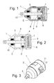
- a train-acting damper 1 comprises a housing 2 with a cylindrical interior, in which a piston 4 is slidably guided, which is held on a piston rod 3. On an outer circumference of the piston 4, a sealing ring 5 is held in a groove, which rests against the inner wall of the housing 2.
- a plate 6 Adjacent to the piston 4, a plate 6 is fixed to one end of the piston rod 3.
- the piston 4 is slightly axially movable on the piston rod 3, so that the distance between the plate 6 and piston 4 is variable.
- an elastic foam 7 is provided on the non-pressurized side in the housing 2, which provides for a certain volume compensation in an extension and retraction of the piston rod 3 from the housing.
- a fluid-filled interior 8 is provided on the opposite side of the piston 4.
- the housing 2 is further closed by a housing cover 9.
- the piston rod 3 is sealed out of the housing 2 by a seal 10.
- FIG. 2 a middle position of the piston 4 in the housing 2 is shown.
- the plate 6 bears against the piston 4.
- the fluid from the inner space 8 between piston rod 3 and piston 4 can flow to the plate 6, to which one or more radial grooves are provided, which are recessed within the plate 6 or in the piston 4 on the side facing the plate 6 can.
- This groove or grooves form radial flow channels in the rebound, so plate 6 and piston 4 are sealingly to each other.
- the narrowest flow cross section is then formed and the damper uses the corresponding throttle properties.
- the flow resistance of the channels through the piston is much smaller than the flow resistance through the radial grooves, for example by a factor of 5 to 500.
- the damper 1 is shown from the outside, in particular, when installed in the furniture, the piston rod 3 is fixed to a component and also the housing 2 is connected to another component. On the housing 2 an annular element is provided for this purpose, on which a spring leg 11 is formed with a bearing pin 12. As a result, a relative movement between the piston rod 3 and the bearing pin 12 or the components connected thereto can be damped.
- FIG. 4 is a slightly modified damper 1 'shown in the operation, however, the damper of Figures 1-3 equivalent.
- the damper 1 ' comprises a housing 2', in which a piston 4 'is guided displaceably together with a piston rod 3'.
- On the piston rod 3 ' is a plate 6' fixed.
- an elastic foam 7 ' is provided for a volume compensation.
- On the opposite side of the piston rod 3 'a closure screw 9' is provided instead of a lid, so that the housing 2 'can be easily filled with a fluid.
- the assembly of the damper housing takes place by axial joining two housing parts, the junction is conveniently located on the non-pressurized side of the damper.
- the connection can be made for example by welding, gluing or by means of circumferential undercut groove.
- FIG. 5 the flow channel between the piston rod 3 'on the piston 4' is shown in detail.
- the piston 4 ' is with an axial play held between the plate 6 'and a shoulder 15 of the piston rod 3', so that the piston 4 'in the axial direction is easily movable.
- a fluid can flow on the right when moving the piston 3 'from the right side to the left side of the piston 4', as indicated by the arrows.
- the piston rod 3 ' is provided with a cylindrical portion 16 which is surrounded by the piston 4', on which are provided to form a flow channel 17 axial openings.
- the flow channel is deflected in the radial direction and at least one radial flow channel 20 is formed between the plate 6' and a radial portion of the piston 4 '. Subsequently, the flow channel is deflected again and between the plate 6 'and the piston 4', an annular flow gap 21 is formed. The narrowest part of the flow channel is the radial flow channel 20, which is relevant to the throttle characteristics.
- the plate 6 ' is in the axial direction relative to the piston rod 3' not movable and fixed to a shoulder 18 of the piston rod 3 'via compression, a rivet 19 or screws.
- FIGS. 6 and 7 is the damper of FIGS. 4 and 5 now being moved in the opposite direction and therefore the fluid is now conveyed from the left side of the piston 4 'to the right side of the piston 4'. Since the piston rod 3 'is pressed in the left direction, the plate 6' rises slightly from the piston 4 ', since the piston 4' with axial play on the piston rod 3 'held until the piston 4' at least in sections the shoulder 15 of the piston rod 3 'is applied. As a result, the cross section of the flow channel 20 'in the radial direction is increased, so that the fluid can reach the opposite side of the piston 4' much easier.
- the foam 7 ' serves to compensate for the difference in volume, which arises by the retraction and extension of the piston rod 3' in or out of the cylindrical housing 2.
- the damper 1 or 1 ' is particularly well suited for furniture, for example, hinges and flap or door stops, since when opening only low damping forces The movement should not hinder the movement and on closing, however, higher damping forces are useful to avoid slamming a door.
- the cross section of the flow channel 20 or 20 ' can be adapted to the desired Dämpfungseigcnschaften. By changing the flow channel by the relative movement of the plate 6 'to the piston 4', the flow channel 20 or 20 'sets in the narrowest area less easy, especially since it is also arranged protected.
- FIG. 8A-8C different embodiments for plates 6 'are shown, which can be mounted on the piston rod 3'.
- the plates have for this purpose a central opening 61 and on the side facing the flow channel 20 and 20 'side small grooves 60 are formed, wherein in Figure 8A two grooves, in FIG. 8B at the plate 6 * four grooves and in FIG. 8C in the plate 6 ** six grooves 60 can be seen.
- the number of grooves and the cross sections of the grooves are critical for the size of the flow channel 20, which can be adapted to the particular application.
- the radial grooves can also be introduced instead of in the plate 6 'or additionally in the piston 4'.
- FIGS 9A and 9B the piston 4 'of the damper is shown in detail.
- the piston 4 ' has inside a cylindrical bore 40 in which the piston rod 3 is slidably guided.
- At the bore 40 is at least one, conveniently three recesses 17 for the formation of flow channels, which form a relatively large flow cross-section for the damping fluid.
- this can flow (almost) unhindered at this point, the small cross-sections acting in the direction of pull with relatively large length are formed by the radial grooves 60 of the plate 6 'when it rests on the piston 4'.
- the piston 4 'an annular receptacle 42 for sealing elements which is limited in the axial direction by two flanges 41 and 43.
- sealing elements known O-rings or other elastic sealing rings can be used.
- dampers whose damping effect is in the pulling direction. It is advantageous that required for mounting joints of the housing lie on the side facing away from the direction of the piston. Thus, these are not acted upon by the high fluid pressure occurring during the damping process, when returning does not occur because of the now large flow cross section no high pressure. This has advantages in terms of the tightness of the arrangement.
- a corresponding reversal of the principle also allows the construction of equally effective pressure dampers.
- the plate attached to the piston rod is arranged on the other side of the piston, the piston is now slidable between the plate and the (riveted) stop located at the end of the piston rod. Accordingly, the joints of the housing and the foam in the cylinder interior are arranged at the opposite end, that is, on the side on which the piston rod emerges.
- a housing part can be designed as a simple pot.
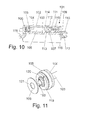
- a damper 101 which comprises a cylindrical housing 102, in which a piston 104 is displaceably guided on a piston rod 103.
- a sealing ring 105 is received in a groove.
- the groove has a width which is greater than the cross section of the sealing ring 105, so that it can be pressed into the groove at too high pressure from the inner wall of the housing 102 in order to avoid excessive friction forces when moving the piston 104.
- the balance piston comprises a sealing ring 107, which is arranged on a retaining ring 111.
- the sealing ring 107 provides a seal to an inner space 108 in the housing 102, wherein the sealing ring 107 has an outer sealing lip 112 which rests against the inside of the housing 102, and has an inner sealing lip 113 which bears against the piston rod 103.
- the seal 107 can simultaneously provide a seal on the piston rod 103 as well as on the housing 102.
- the seal 107 and the retaining ring 111 are biased by a spring 110 which abuts against the retaining ring 111 and on the opposite side to a cover 109.
- the cover 109 is only latched to the housing 102, since the forces due to the spring 110 are low.
- a locking element 115 is fixed via a detent 116 to a groove or embossment which forms a partially open eyelet 117, so that another component, such as a furniture hinge can be snapped over the legs on the eyelet 117, so a simple Assembly is possible.
- the latching element 115 does not detach from the piston rod 103, as a pulling out of the piston rod 103 is smooth and the holding forces of the individual latching means are greater than the counteracting forces when pulling out the piston rod 103.
- the latching lugs 116 may be provided on the piston rod 103 an embossing , so that no machining of the piston rod 103 is required.
- the piston rod 103 made of metal or plastic can be made very thin in diameter, preferably in a range between 1.5 mm to 3.5 mm, in particular 2.0 mm to 3.0 mm. As a result, only a small volume compensation is required when retracting and extending the piston rod 103.
- the damper 101 is designed as a pressure damper, in which the force for retracting the piston rod 103 at least five times, preferably eight to twelve times greater than the force to pull out the piston rod 103rd
- a flow channel 120 is formed, which is partially formed by two diametrically opposite to the axis of the piston rod 103 radial grooves 160.
- the outer diameter of the plate 106 is smaller than the diameter of the piston 104.
- an opening 121 is recessed centrally, so that the plate 106 can be plugged onto a pin-shaped end 119 of the piston rod 103 or the piston 104.
- the pin-shaped end 119 is then deformed, so that the plate is held securely on the piston 104.
- FIG. 12 a deformed end 119 'is shown which fixes the plate 106 to the piston 104 instead of the piston rod 103, as well as other attachment mechanisms can be used.
- the piston 104 one or more passage channels 122 are formed, which extend parallel to the axis of the piston rod 103.
- the plate 106 bends away from the piston 104 until, for example, the position 106 'is reached and the grooves 160 are spaced from the plate 106 and the fluid can flow from the inner space 108 through the passageways 122 to the inner space 123, without necessarily passing through the grooves 160.
- the plate is formed bendable and consists for example of plastic, preferably of a plastic film PET, so that after movement of the piston rod 103, the plate 106 moves back to the position adjacent to the piston 104 perpendicular to the axis of the piston rod 103.
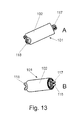
- the housing 102 has on one side an outwardly open eyelet 118, wherein on the opposite side of the outwardly open eyelet 117 of the locking element 115 can be seen on the piston rod 103. Both eyelets 117 and 118 allow easy and quick assembly of the damper 101st
- FIG. 14 a further embodiment of a damper 1 "is shown, which is similar to the embodiment of the FIGS. 1 to 3 is trained.
- a piston 4" with an outer sealing ring 5 "out, on which a Kolbestange 3" is performed.
- the piston rod 3 "passes through the housing 2" on one side and is sealed off by a seal 10 ".A platen 6" is in turn adjacent to the piston 4 " arranged, between the piston 4 "and the plate 6" radial flow portions are formed, as in the embodiments of the FIGS. 4 to 9 is shown.
- a chamber 70 with an elastic foam 7 is provided, which is arranged laterally offset to a longitudinal axis of the piston rod 3 ", thus adjacent to an eyelet 11" for rotatably supporting the housing 2 " the chamber 70 with the foam 7 "not the distance between the eyelet 11” for fixing the housing 2 "and the opposite end of the piston rod 3", so that the space, for example, in a furniture hinge can be optimally used.
- FIG. 15 is a in the region of a piston 204 with respect to the embodiment of FIG. 10 shown slightly modified embodiment.
- the piston 204 is slidable in a cylindrical housing 202 of the damper.
- the piston 204 is fixed via a detent or bayonet connection to a piston rod 203 and has at least one axial flow channel 222.
- a groove is provided in a trained as an O-ring sealing ring 205 is inserted so that the chambers formed on opposite sides of the piston 204 223 and 224 via the piston 204 and the sealing ring 205 are separated from each other.
- a slotted support ring 209 Adjacent to the sealing ring 205, a slotted support ring 209 made of a rigid material, such as plastic or metal is inserted in the groove, which avoids a displacement of the sealing ring 205 in the groove and the sealing ring 205 can also compress in the axial direction. Because at high pressures, the sealing ring 205 can otherwise slip in the groove so that sufficient tightness is no longer guaranteed and the damper is no longer functional.
- a plate 206 is provided on the piston 204, which is axially secured to a cylindrical extension 210 by a snap ring 207.
- the plate 206 is held with axial clearance between the snap ring 207 and a side surface 208 of the piston 204, so that upon movement of the piston 204, the plate 206 abuts either the side surface 208 or the snap ring 207, and thus as in the previous embodiments flow channel in the range of radial grooves on the plate 206 and / or on the side surface 208 is increased or decreased.
- the fluid used for the dampers shown is preferably an oil, in particular silicone oil, but also other fluids can be used for damping.
Abstract
Description
Die vorliegende Erfindung betrifft einen Dämpfer für Möbel, insbesondere für Scharniere, mit einem Gehäuse, in dem ein mit einer Kolbenstange verbundener Kolben verschiebbar aufgenommen ist, wobei ein Fluid bei einer Bewegung des Kolbens innerhalb des Gehäuses durch einen Strömungskanal am oder im Kolben strömt, wobei bei Bewegung des Kolbens in unterschiedliche Richtungen eine unterschiedliche Dämpfungskraft erhalten wird.The present invention relates to a damper for furniture, in particular for hinges, comprising a housing in which a piston connected to a piston rod is slidably received, wherein a fluid flows during a movement of the piston within the housing through a flow channel on or in the piston upon movement of the piston in different directions a different damping force is obtained.
Es gibt Dämpfer für Möbel, bei denen in einem Kolben eine Mikrobohrung angeordnet ist, sodass ein Fluid bei Bewegung des Kolbens von einer Seite des Kolbens zur anderen strömen kann, so dass die Bewegung des Kolbens durch das Fluid gedämpft ist. Bei der Herstellung solcher Mikrobohrungen, die meist kleiner als 0,15 mm sind, besteht der Nachteil, dass der Herstellungsprozess zeitaufwendig ist, da einen hohe Genauigkeit gefordert wird und zudem die Werkzeuge einem hohen Verschleiß unterliegen. Bei geringen Maßabweichungen können die Dämpfungskräfte völlig unterschiedliche ausfallen. Zudem können Mikrobohrungen durch kleine Partikel leicht verstopfen. Daher ist der Einsatz von Schaumstoffelementen zum Volumenausgleich nicht möglich, da losgelöste kleine Partikel das System blockieren könnten. Schließlich wird bei kleinen Mikrobohrungen die Wand ausgewaschen, sodass sich der Durchmesser nach gewisser Zeit vergrößert. Dadurch ändern sich die Eigenschaften des Dämpfers.There are dampers for furniture in which a microbore is disposed in a piston so that fluid can flow from one side of the piston to the other as the piston moves, such that movement of the piston is damped by the fluid. In the production of such micro-bores, which are usually smaller than 0.15 mm, there is the disadvantage that the manufacturing process is time-consuming, since a high accuracy is required and also the tools are subject to high wear. With small deviations, the damping forces can be completely different. In addition, microbores can easily become clogged by small particles. Therefore, the use of foam elements for volume compensation is not possible because detached small particles could block the system. Finally, with small microbores, the wall is washed out so that the diameter increases after a certain time. This will change the characteristics of the damper.
Ferner sind Dämpfer bekannt, bei denen das Fluid über einen Ringspalt zwischen Kolben und Gehäusewand strömt. Auch hier haben geringste Maßabweichungen am Kolbendurchmesser oder beim Zylinderinnendurchmesser große Auswirkungen auf das Dämpfungsverhalten. Toleranzen können sich addieren und insbesondere kann bei Veränderung des Innendrucks sich die Gehäusewand aufbiegen und den Ringspalt vergrößern. Zudem können sich auch hier Verunreinigungen nachteilig auf das Dämpfungsverhalten auswirken.Furthermore, dampers are known in which the fluid flows through an annular gap between the piston and the housing wall. Here, too, the smallest deviations in the diameter of the piston or in the inner diameter of the cylinder have a major effect on the damping behavior. Tolerances can add up and, in particular, the housing wall can bend when the internal pressure changes and increase the annular gap. In addition, impurities can also adversely affect the damping behavior here.
Aus der
Aus der
Es ist daher Aufgabe der vorliegenden Erfindung, einen Dämpfer für Möbel zu schaffen, der in der Benutzung unempfindlich ist und individuell an den jeweiligen Einsatzzweck relativ genau angepasst werden kann.It is therefore an object of the present invention to provide a damper for furniture that is insensitive to use and can be adapted to the particular application relatively accurately.
Diese Aufgabe wird mit einem Dämpfer mit den Merkmalen des Anspruches 1 gelöst.This object is achieved with a damper with the features of
Wenn der Dämpfer als Druckdämpfer ausgebildet ist, können an der Kolbenstange und/oder dem Gehäuse Rastmittel, vorzugsweise mit biegbaren Schenkeln, zum Verbinden mit einem weiteren Bauteil vorgesehen sein, da die Zugbelastungen bei der Bewegung der Kolbenstange geringer sind als die Haltekräfte der Rastmittel, so dass der Dämpfer einfach und schnell montiert und auch nachgerüstet werden kann.If the damper is designed as a pressure damper, can be provided on the piston rod and / or the housing locking means, preferably with bendable legs, for connection to another component, since the tensile loads during the movement of the piston rod are smaller than the holding forces of the locking means, so that the damper can be easily and quickly mounted and retrofitted.
Vorzugsweise ist der Querschnitt des Strömungskanals bereichsweise veränderbar, indem der Kolben relativ zu einer Platte bewegbar ist, wobei die Platte und/oder der Kolben sich radial erstreckende Nuten aufweist, die zumindest einen Teil des Strömungskanals bilden. Dadurch kann der Querschnitt des Strömungskanals relativ genau vorgegeben werden, wobei die an dem Kolben gelagerte Platte leicht herstellbar ist und sich bei Bedarf auch auswechseln lässt. Zudem kann der Dämpfer auf einfache Weise auf den jeweiligen Einsatzzweck eingestellt werden, da die Dämpfungskraft hauptsächlich von der Gestaltung des Strömungskanals am oder im Kolben abhängt, insbesondere vom Strömungsquerschnitt der radialen Nuten, die nicht nur eine Blende bilden, sondern von dem Fluid über eine gewisse Wegstrecke durchströmt werden. Diese Wegstrecke der radialen Nut kann vollständig zur Erzeugung von Reibungskräften und damit für einen Druckabfall des Fluides verwendet werden, was dann die Dämpfung bewirkt. Zudem lassen sich die Nuten wesentlich einfacher herstellen als Bohrungen durch Bohrwerkzeuge, da dabei Grate entstehen können, oder Öffnungen im Spritzgussverfahren, bei denen Spritzgusshäute gebildet werden können. Durch die Veränderung des Strömungskanals zwischen der Platte und dem Kolben kann sich diese zudem weniger leicht durch Verschmutzungen zusetzen, da Teile durch die Veränderung des Querschnittes nicht so leicht einklemmen können.Preferably, the cross section of the flow channel is partially variable by the piston is movable relative to a plate, wherein the plate and / or the piston has radially extending grooves which form at least part of the flow channel. As a result, the cross-section of the flow channel can be set relatively precisely, with the plate mounted on the piston being easy to produce is and can be replaced if necessary. In addition, the damper can be easily adjusted to the particular application, since the damping force depends mainly on the design of the flow channel on or in the piston, in particular the flow cross-section of the radial grooves, which not only form a diaphragm, but of the fluid over a certain Flowed through the route. This distance of the radial groove can be completely used to generate frictional forces and thus a pressure drop of the fluid, which then causes the damping. In addition, the grooves can be much easier to produce than drilling by drilling tools, since this can cause burrs, or openings in the injection molding process, in which injection molded skins can be formed. By changing the flow channel between the plate and the piston, this can also be less easily clogged by contamination, as parts can not pinch so easily by the change in the cross section.
Gemäß einer bevorzugten Ausgestaltung der Erfindung sind der Kolben und die Platte gemeinsam auf einer Kolbenstange gelagert. Zur Veränderung des Querschnitt des Strömungskanals kann der Kolben in axiale Richtung bewegt werden, so dass ein radialer Abschnitt zwischen Kolben und Platte eine Art Ventilfunktion besitzt und die Bewegung des Kolbens in einer Richtung stärker gedämpft ist als in die gegenüberliegende Richtung. Dies ist insbesondere bei Möbeln ein Vorteil, da die Öffnungsbewegung leichtgängig erfolgen soll, aber beim Schließen eine Dämpfung von Vorteil ist. Die Dämpfungskraft kann in die gegenüberliegenden Bewegungsrichtungen des Kolbens um einen Faktor größer 5, vorzugsweise um einen Faktor 8 bis 12 unterschiedlich sein.According to a preferred embodiment of the invention, the piston and the plate are mounted together on a piston rod. To change the cross-section of the flow channel, the piston can be moved in the axial direction, so that a radial portion between the piston and plate has a kind of valve function and the movement of the piston is more damped in one direction than in the opposite direction. This is an advantage especially in furniture, since the opening movement should be smooth, but when closing a damping is beneficial. The damping force may be different in the opposite directions of movement of the piston by a factor greater than 5, preferably by a factor of 8 to 12.
Vorzugsweise ist die Platte an der Kolbenstange festgelegt und der Kolben mit Spiel an der Kolbenstange gehalten. Dadurch kann mit wenigen Bauteilen ein Dämpfer bereitgestellt werden, bei dem der Strömungskanal verändert werden kann. Der Kolben kann dabei die Kolbenstange ringförmig umgeben und zwischen einer Platte und einer Schulter an der Kolbenstange bewegbar gehalten sein. Dadurch kann der Strömungskanal zwischen Kolben und Kolbenstange konstant bleiben, beispielsweise können entsprechende Ausnehmungen an einer ansonsten zylindrischen Aufnahme des Kolben vorgesehen sein. Aufgrund des axialen Spiels des Kolbens wird dann ein in radiale Richtung verlaufender Abschnitt des Strömungskanals im Querschnitt verändert. Dort kann dann der engste Querschnitt des Strömungskanals gebildet sein, der für die Drosseleigenschaften relevant ist. Die radialen Nuten sind dabei vorzugsweise so angeordnet, dass jeweils zwei diametral zur Kolbenachse gegenüberliegende Nuten vorgesehen sind. Dies gewährleistet eine gleichmäßige Dämpfungskraft und verhindert mögliche Querkräfte in radialer Richtung, die für ein Verklemmen des Kolbens sorgen könnten.Preferably, the plate is fixed to the piston rod and the piston held with play on the piston rod. This can be provided with few components, a damper, in which the flow channel can be changed. The piston can thereby surround the piston rod annularly and be movably held between a plate and a shoulder on the piston rod. Thereby, the flow channel between the piston and piston rod remain constant, for example, corresponding recesses may be provided on an otherwise cylindrical receptacle of the piston. Due to the axial play the piston is then changed in the radial direction extending portion of the flow channel in cross section. There then the narrowest cross-section of the flow channel may be formed, which is relevant to the throttle characteristics. The radial grooves are preferably arranged so that in each case two diametrically opposite to the piston axis grooves are provided. This ensures a uniform damping force and prevents possible transverse forces in the radial direction, which could cause jamming of the piston.
Gemäß einer weiteren Ausgestaltung der Erfindung ist die Platte an einer topfförmigen Aufnahme des Kolbens angeordnet. Zudem kann im Gehäuse benachbart zu dem Fluid ein elastischer Schaumstoff angeordnet sein, der einen gewissen Volumenausgleich für die ein- und ausfahrende Kolbenstange vornehmen kann. Für eine optimale Raumausnutzung kann die Kammer mit dem elastischen Schaumstoff versetzt zu der Längsachse der Kolbenstange angeordnet sein, so dass in einem Bauteil vorhandener Raum durch die Kammer genutzt wird und der Dämpfer im übrigen sehr kurz ausgebildet sein kann.According to a further embodiment of the invention, the plate is arranged on a cup-shaped receptacle of the piston. In addition, an elastic foam can be arranged in the housing adjacent to the fluid, which can make a certain volume compensation for the retracting and extending piston rod. For optimum space utilization, the chamber can be arranged offset with the elastic foam to the longitudinal axis of the piston rod, so that in a component existing space is used by the chamber and the damper can be made otherwise very short.
Gemäß einer weiteren Ausführungsform ist zur Veränderung des Querschnitts des Strömungskanals der Kolben fest und die Platte biegbar ausgebildet. Dadurch kann der Dämpfer auf einfache Weise als Druckdämpfer ausgebildet sein, der beim Eindrücken der Kolbenstange in das Gehäuse schwergängig ist, während ein Herausziehen der Kolbenstange vergleichsweise leichtgängig erfolgen kann. Die Platte kann dabei als Scheibe aus Kunststoff, vorzugsweise aus einer Kunststofffolie, gebildet sein, da die Beanspruchung der Scheibe auch im Bereich des Strömungskanals relativ gering ist.According to a further embodiment, the piston is fixed and the plate bendable to change the cross section of the flow channel. As a result, the damper can be designed in a simple manner as a pressure damper, which is stiff when the piston rod is pressed into the housing, while the piston rod can be pulled out relatively easily. The plate can be formed as a disc made of plastic, preferably from a plastic film, since the stress of the disc is relatively low in the region of the flow channel.
Auf einer Seite des Gehäuses ist vorzugsweise ein bewegbarer Ausgleichskolben vorgesehen, der abgedichtet an dem Gehäuse und der Kolbenstange geführt ist. Durch den Ausgleichskolben kann eine Volumenveränderung durch die Bewegung der Kolbenstange kompensiert werden. Der Ausgleichskolben kann dabei eine Dichtung aufweisen oder aus ihr bestehen, wobei die Dichtung mit einer äußeren Dichtlippe am Gehäuse und mit einer inneren Dichtlippe an der Kolbenstange anliegt, so dass nur eine einzige Dichtung notwendig ist. Ferner kann der Ausgleichskolben vorzugsweise durch eine Feder zu dem Innenraum mit dem Kolben hin vorgespannt sein, die einen leichten Innendruck in dem Gehäuse erzeugt. Dabei kann die Feder an einem Deckel abgestützt sein, der an dem Gehäuse festgelegt ist und von der Kolbenstange durchgriffen ist, so dass ein einfach zu montierender Aufbau gegeben ist.On one side of the housing, a movable compensating piston is preferably provided which is sealed to the housing and the piston rod. By the balance piston, a change in volume can be compensated by the movement of the piston rod. The balance piston can have a seal or consist of it, wherein the seal with an outer sealing lip on the housing and an inner sealing lip rests against the piston rod, so that only a single seal is necessary. Further, the balance piston is preferably biased by a spring toward the interior with the piston be, which generates a slight internal pressure in the housing. In this case, the spring may be supported on a cover, which is fixed to the housing and is penetrated by the piston rod, so that an easy to install structure is given.
Die Erfindung wird nachfolgend anhand von mehreren Ausführungsbeispielen mit Bezug auf die beigefügten Zeichnungen näher erläutert. Es zeigen:
Figur 1- eine geschnittene Seitenansicht eines ersten Ausführungsbeispieles eines erfindungsgemäßen Dämpfers;
Figur 2- eine geschnittene Seitenansicht des Dämpfers der
Figur 1 Figur 3- eine perspektivische Ansicht des Dämpfers der
Figur 1 Figur 4- eine geschnittene Seitenansicht eines Dämpfers gemäß einem zweiten Ausführungsbeispiel;
Figur 5- eine Detailansicht der
Figur 4 Figur 6- eine geschnittene Seitenansicht des Dämpfers der
Figur 4 Figur 7- eine Detailansicht des Dämpfers der
Figur 6 - Figuren 8A-8C
- verschiedene Ansichten von Platten für den
Dämpfer der Figur 4 ; - Figur 9A und 9B
- zwei Detailansichten des Kolbens des Dämpfers der
Figur 6 ; Figur 10- eine teilweise geschnittene Seitenansicht einer weiteren Ausführungsform eines Dämpfers;
Figur 11- eine perspektivische Detailansicht des Dämpfers der
Figur 10 ; Figur 12- eine schematische Ansicht des Dämpfers der
Figur 10 im Bereich des Kolbens; - Figur 13A und 13B
- zwei Ansichten des Dämpfers der
Figur 10 ; - Figur 14
- eine modifizierte Ausführungsform eines Dämpfers, und
Figur 15- eine Detailansicht eines zu dem Ausführungsbeispiel der
Figur 10 modifizierten Dämpfers.
- FIG. 1
- a sectional side view of a first embodiment of a damper according to the invention;
- FIG. 2
- a sectional side view of the damper of the
FIG. 1 in a middle position; - FIG. 3
- a perspective view of the damper of
FIG. 1 ; - FIG. 4
- a sectional side view of a damper according to a second embodiment;
- FIG. 5
- a detailed view of the
FIG. 4 ; - FIG. 6
- a sectional side view of the damper of the
FIG. 4 in a modified position; - FIG. 7
- a detail view of the damper of
FIG. 6 ; - Figures 8A-8C
- different views of plates for the damper of
FIG. 4 ; - FIGS. 9A and 9B
- two detailed views of the piston of the damper the
FIG. 6 ; - FIG. 10
- a partially sectioned side view of another embodiment of a damper;
- FIG. 11
- a detailed perspective view of the damper of
FIG. 10 ; - FIG. 12
- a schematic view of the damper of
FIG. 10 in the area of the piston; - FIGS. 13A and 13B
- two views of the damper the
FIG. 10 ; - FIG. 14
- a modified embodiment of a damper, and
- FIG. 15
- a detailed view of one of the embodiment of the
FIG. 10 modified damper.
Ein auf Zug wirkender Dämpfer 1 umfasst ein Gehäuse 2 mit einem zylindrischen Innenraum, in dem ein Kolben 4 verschiebbar geführt ist, der an einer Kolbenstange 3 gehalten ist. An einem äußeren Umfang des Kolbens 4 ist in einer Nut ein Dichtring 5 gehalten, der an der Innenwand des Gehäuses 2 anliegt.A train-acting
Benachbart zu dem Kolben 4 ist an einem Ende der Kolbenstange 3 eine Platte 6 fixiert. Der Kolben 4 ist an der Kolbenstange 3 geringfügig axial bewegbar, so dass der Abstand zwischen Platte 6 und Kolben 4 veränderbar ist.Adjacent to the
Benachbart zu der Platte 6 ist auf der drucklosen Seite in dem Gehäuse 2 ein elastischer Schaumstoff 7 vorgesehen, der für einen gewissen Volumenausgleich bei einem Ein- und Ausfahren der Kolbenstange 3 aus dem Gehäuse sorgt. Auf der gegenüberliegenden Seite des Kolbens 4 ist ein mit Fluid gefüllter Innenraum 8 vorgesehen. Das Gehäuse 2 ist ferner durch einen Gehäusedeckel 9 verschlossen. Auf der zu dem Deckel 9 gegenüberliegenden Seite ist die Kolbenstange 3 durch eine Dichtung 10 abgedichtet aus dem Gehäuse 2 herausgeführt.Adjacent to the
In
Wird die Kolbenstange 3 in die entgegengesetzte Richtung bewegt, so wird die Platte 6 leicht von dem Kolben 4 weg bewegt, da der Kolben 4 mit axialem Spiel an der Kolbenstange 3 gehalten ist. Dadurch vergrößert sich der Querschnitt des Strömungskanals zwischen Platte 6 und Kolben 4 und das Fluid kann mit geringerem Strömungswiderstand zu dem Innenraum 8 strömen.When the
In
In
In
Die Platte 6' ist dabei in axiale Richtung relativ zu der Kolbenstange 3' nicht bewegbar und an einer Schulter 18 der Kolbenstange 3' über Verpressung, einen Niet 19 oder über Schrauben festgelegt.The plate 6 'is in the axial direction relative to the piston rod 3' not movable and fixed to a
In den
Der Schaumstoff 7' dient dabei zum Ausgleich des Differenzvolumens, das durch das Ein- und Ausfahren der Kolbenstange 3' in oder aus dem zylindrischen Gehäuse 2 entsteht.The foam 7 'serves to compensate for the difference in volume, which arises by the retraction and extension of the piston rod 3' in or out of the
Der Dämpfer 1 bzw. 1' eignet sich besonders gut für Möbel beispielsweise Scharniere und Klappen- bzw. Türanschläge, da beim Öffnen nur geringe Dämpfungskräfte die Bewegung nicht behindern sollen und beim Schließen hingegen höhere Dämpfungskräfte nützlich sind, um ein Zuschlagen einer Tür zu vermeiden. Der Querschnitt des Strömungskanals 20 bzw. 20' kann dabei an die gewünschten Dämpfungseigcnschaften angepasst werden. Durch die Veränderung des Strömungskanals durch die Relativbewegung der Platte 6' zu dem Kolben 4' setzt sich der Strömungskanal 20 bzw. 20' im engsten Bereich weniger leicht zu, insbesondere da er auch geschützt angeordnet ist.The
In den
In
Randseitig weist der Kolben 4' eine ringförmige Aufnahme 42 für Dichtelemente auf, die in axiale Richtung durch zwei Flansche 41 und 43 begrenzt ist. Als Dichtelemente können bekannt O-Ringe oder andere elastische Dichtringe eingesetzt werden.On the edge side, the piston 4 'an
Die obigen Ausführungsbeispiele zeigen Dämpfer, deren Dämpfungswirkung in Zugrichtung liegt. Dabei ist vorteilhaft, dass für die Montage erforderliche Verbindungsstellen des Gehäuses auf der der Zugrichtung abgewandten Seite des Kolbens liegen. Somit werden diese nicht mit dem während des Dämpfungsvorganges auftretenden hohen Fluiddruck beaufschlagt, beim Zurückfahren tritt wegen des nun großen Strömungsquerschnitts kein hoher Druck auf. Dies hat Vorteile hinsichtlich der Dichtigkeit der Anordnung. Eine entsprechende Umkehrung des Prinzips ermöglicht auch den Bau von gleichwirkenden Druckdämpfern. Dazu wird die an der Kolbenstange befestigte Platte auf der anderen Seite des Kolbens angeordnet, der Kolben ist nun verschieblich zwischen der Platte und dem am Ende der Kolbenstange befindlichen (genieteten) Anschlag. Entsprechend werden auch die Fügestellen des Gehäuses und der Schaumstoff im Zylinderinneren am entgegengesetzten Ende angeordnet, das heißt auf der Seite, an der die Kolbenstange austritt. Somit kann ein Gehäuseteil als einfacher Topf gestaltet werden.The above embodiments show dampers whose damping effect is in the pulling direction. It is advantageous that required for mounting joints of the housing lie on the side facing away from the direction of the piston. Thus, these are not acted upon by the high fluid pressure occurring during the damping process, when returning does not occur because of the now large flow cross section no high pressure. This has advantages in terms of the tightness of the arrangement. A corresponding reversal of the principle also allows the construction of equally effective pressure dampers. For this purpose, the plate attached to the piston rod is arranged on the other side of the piston, the piston is now slidable between the plate and the (riveted) stop located at the end of the piston rod. Accordingly, the joints of the housing and the foam in the cylinder interior are arranged at the opposite end, that is, on the side on which the piston rod emerges. Thus, a housing part can be designed as a simple pot.
Bei der in den
Benachbart zu dem Kolben 104 ist an einem Ende der Kolbenstange 103 oder an einem Fortsatz des Kolbens 104 eine Platte 106 fixiert. An der gegenüberliegenden Seite des Kolbens 104 ist ein Augleichskolben in dem Gehäuse 102 aufgenommen, der eine Volumenänderung aufgrund des Bewegens der Kolbenstange 103 kompensiert. Der Ausgleichskolben umfasst einen Dichtring 107, der an einem Haltering 111 angeordnet ist. Der Dichtring 107 stellt eine Abdichtung zu einem Innenraum 108 in dem Gehäuse 102 her, wobei der Dichtring 107 eine äußere Dichtlippe 112 besitzt, die an der Innenseite des Gehäuses 102 anliegt, sowie eine innere Dichtlippe 113 besitzt, die an der Kolbenstange 103 anliegt. Dadurch kann die Dichtung 107 gleichzeitig eine Abdichtung an der Kolbenstange 103 als auch an dem Gehäuse 102 bereitstellen.Adjacent to the
Die Dichtung 107 und der Haltering 111 sind über eine Feder 110 vorgespannt, die an dem Haltering 111 und an der gegenüberliegenden Seite an einem Deckel 109 anliegt. Der Deckel 109 ist dabei nur rastend an dem Gehäuse 102 festgelegt, da die Kräfte aufgrund der Feder 110 gering sind.The
An der Kolbenstange 103 ist ein Rastelement 115 über eine Rastnase 116 an einer Nut oder Verprägung fixiert, das eine teilweise offene Öse 117 ausbildet, so dass ein weiteres Bauteil, beispielsweise eines Möbelscharniers über die Schenkel an der Öse 117 eingerastet werden kann, also eine einfach Montage möglich ist. Das Rastelement 115 löst sich nicht von der Kolbenstange 103, da ein Herausziehen der Kolbenstange 103 leichtgängig erfolgt und die Haltekräfte der einzelnen Rastmittel größer sind als die entgegenwirkenden Kräfte beim Herausziehen der Kolbenstange 103. Für die Rastnasen 116 kann an der Kolbenstange 103 eine Verprägung vorgesehen sein, so dass keine spanende Bearbeitung der Kolbenstange 103 erforderlich ist. Dadurch kann die aus Metall oder Kunststoff bestehenden Kolbenstange 103 im Durchmesser sehr dünn ausgebildet sein, vorzugsweise in einem Bereich zwischen 1,5mm bis 3,5 mm, insbesondere 2,0 mm bis 3,0 mm. Dadurch wird bei Ein- und Ausfahren der Kolbenstange 103 nur ein geringer Volumenausgleich notwendig.On the
Der Dämpfer 101 ist als Druckdämpfer ausgebildet, bei dem die Kraft zum Einfahren der Kolbenstange 103 mindestens fünfmal, vorzugsweise acht bis zwölf mal größer ist als die Kraft zum Herausziehen der Kolbenstange 103.The
Zwischen dem Kolben 104 und der ringförmigen Platte 106 ist ein Strömungskanal 120 ausgebildet, der abschnittsweise durch zwei sich diametral zur Achse der Kolbenstange 103 gegenüberliegende radiale Nuten 160 gebildet ist. Der äußere Durchmesser der Platte 106 ist dabei geringer als der Durchmesser des Kolbens 104. In der Platte 106 ist eine Öffnung 121 mittig ausgespart, so dass die Platte 106 auf ein zapfenförmiges Ende 119 der Kolbenstange 103 oder des Kolbens 104 aufgesteckt werden kann. Zur Fixierung der Platte 106 wird dann das zapfenförmige Ende 119 verformt, so dass die Platte sicher an dem Kolben 104 gehalten ist.Between the
In
Wird an der Kolbenstange 103 gezogen (untere Hälfte der
In den
In
Für den Volumenausgleich ist in dem Gehäuse 2" eine Kammer 70 mit einem elastischen Schaumstoff 7" vorgesehen, die zu einer Längsachse der Kolbenstange 3" seitlich versetzt angeordnet ist, also benachbart zu einer Öse 11" zur drehbaren Lagerung des Gehäuses 2". Dadurch verlängert die Kammer 70 mit dem Schaumstoff 7" nicht den Abstand zwischen der Öse 11" zur Befestigung des Gehäuses 2" und dem gegenüberliegenden Ende der Kolbenstange 3", so dass der Bauraum, beispielsweise in einem Möbelscharnier optimal genutzt werden kann.For the volume compensation in the
In
Auf der Seite der Kammer 223 ist an dem Kolben 204 eine Platte 206 vorgesehen, die an einem zylindrischen Fortsatz 210 durch einen Sprengring 207 axial gesichert ist. Die Platte 206 ist mit axialem Spiel zwischen dem Sprengring 207 und einer Seitenfläche 208 des Kolbens 204 gehalten, so dass bei einer Bewegung des Kolbens 204 die Platte 206 entweder an der Seitenfläche 208 oder am Sprengring 207 anliegt, und somit wie bei den vorangegangenen Ausführungsbeispielen ein Strömungskanal im Bereich von radialen Nuten an der Platte 206 und/oder an der Seitenfläche 208 vergrößert oder verkleinert wird.On the side of the
Als Fluid wird für die gezeigten Dämpfer vorzugsweise ein Öl, insbesondere Silikonöl, eingesetzt, aber auch andere Fluide können zur Dämpfung verwendet werden.The fluid used for the dampers shown is preferably an oil, in particular silicone oil, but also other fluids can be used for damping.
Claims (10)
Applications Claiming Priority (2)
| Application Number | Priority Date | Filing Date | Title |
|---|---|---|---|
| DE202006003197U DE202006003197U1 (en) | 2006-03-01 | 2006-03-01 | Damper for furniture |
| EP07712338A EP2010741B1 (en) | 2006-03-01 | 2007-02-27 | Damper for furniture |
Related Parent Applications (2)
| Application Number | Title | Priority Date | Filing Date |
|---|---|---|---|
| EP07712338.8 Division | 2007-02-27 | ||
| EP07712338A Division EP2010741B1 (en) | 2006-03-01 | 2007-02-27 | Damper for furniture |
Publications (2)
| Publication Number | Publication Date |
|---|---|
| EP2006480A1 true EP2006480A1 (en) | 2008-12-24 |
| EP2006480B1 EP2006480B1 (en) | 2012-12-19 |
Family
ID=38017052
Family Applications (2)
| Application Number | Title | Priority Date | Filing Date |
|---|---|---|---|
| EP08164908A Active EP2006480B1 (en) | 2006-03-01 | 2007-02-27 | Damper for furniture |
| EP07712338A Active EP2010741B1 (en) | 2006-03-01 | 2007-02-27 | Damper for furniture |
Family Applications After (1)
| Application Number | Title | Priority Date | Filing Date |
|---|---|---|---|
| EP07712338A Active EP2010741B1 (en) | 2006-03-01 | 2007-02-27 | Damper for furniture |
Country Status (10)
| Country | Link |
|---|---|
| EP (2) | EP2006480B1 (en) |
| JP (1) | JP5270376B2 (en) |
| KR (1) | KR101508482B1 (en) |
| CN (1) | CN101395333B (en) |
| AT (1) | ATE519911T1 (en) |
| DE (1) | DE202006003197U1 (en) |
| ES (2) | ES2401528T3 (en) |
| RU (1) | RU2425941C2 (en) |
| TW (1) | TWI387691B (en) |
| WO (1) | WO2007099100A2 (en) |
Cited By (7)
| Publication number | Priority date | Publication date | Assignee | Title |
|---|---|---|---|---|
| CN105264257A (en) * | 2013-01-31 | 2016-01-20 | 京特·齐默尔 | Cylinder-piston unit with piston throttle |
| DE102015015170B3 (en) * | 2015-11-26 | 2016-12-15 | Günther Zimmer | Cylinder-piston unit with compensating sealing element |
| WO2019002130A1 (en) * | 2017-06-29 | 2019-01-03 | Druck- und Spritzgußwerk Hettich GmbH & Co. KG | Damper |
| DE102017010876A1 (en) * | 2017-11-24 | 2019-05-29 | Günther Zimmer | Cylinder-piston unit with load-dependent throttle |
| WO2020001936A1 (en) | 2018-06-26 | 2020-01-02 | Druck- Und Spritzgusswerk Hettich GmbH & Co. KG | Damper |
| RU2784115C2 (en) * | 2018-06-26 | 2022-11-23 | Друк- Унд Шприцгусверк Хеттих Гмбх Унд Ко. Кг | Damper |
| WO2023101622A1 (en) * | 2021-12-01 | 2023-06-08 | Samet Kalip Ve Madeni̇ Eşya San Ve Ti̇c. A.Ş | A hydraulic damper for furniture doors and drawers |
Families Citing this family (17)
| Publication number | Priority date | Publication date | Assignee | Title |
|---|---|---|---|---|
| DE202007011194U1 (en) | 2007-08-10 | 2008-12-24 | Hettich-Oni Gmbh & Co. Kg | hinge |
| DE202008011190U1 (en) * | 2008-08-22 | 2009-12-31 | Hettich-Oni Gmbh & Co. Kg | Hinge and tool for disassembling a linear damper from a hinge |
| DE202009004751U1 (en) | 2009-04-28 | 2010-09-09 | Druck- und Spritzgußwerk Hettich GmbH & Co. KG | Damper for furniture |
| DE202009004752U1 (en) | 2009-04-28 | 2010-09-09 | Druck- und Spritzgußwerk Hettich GmbH & Co. KG | Damper for furniture |
| IT1398554B1 (en) | 2010-03-08 | 2013-03-01 | Guiros S P A Ora Guiros S R L | SHOCK |
| AT510375B1 (en) | 2010-08-27 | 2018-06-15 | Blum Gmbh Julius | FURNITURE SHOCKS |
| DE102011122220A1 (en) * | 2011-12-23 | 2013-06-27 | Grass Gmbh | Damping device for use in furniture fitting of movable furniture part e.g. drawer, has damper link moveably linked to furniture part, where kinetic energy of link is absorbed by damping fluid containing damping liquid and emulsifying agent |
| ITMI20130344A1 (en) | 2013-03-07 | 2014-09-08 | Brera Cerniere Srl | FLUID SHOCK ABSORBER, PARTICULARLY FOR HOUSEHOLD APPLIANCES SUCH AS OVENS, DISHWASHER OR SIMILAR OR FOR FURNISHING COMPONENTS SUCH AS DOORS OR DRAWERS, SIMPLY EASY TO REALIZE. |
| AT514663B1 (en) * | 2013-07-18 | 2015-05-15 | Blum Gmbh Julius | Damper for movable furniture parts |
| TWI596287B (en) * | 2013-07-26 | 2017-08-21 | Damper | |
| CN103615494A (en) * | 2013-11-29 | 2014-03-05 | 常州大学 | Damper used for vibration reduction of pipeline |
| CN104653686B (en) * | 2015-02-06 | 2017-02-01 | 伍志勇 | Buffer with controllable buffering force |
| AT520128A1 (en) * | 2017-07-13 | 2019-01-15 | Blum Gmbh Julius | furniture damper |
| WO2019025568A1 (en) | 2017-08-02 | 2019-02-07 | Wolfgang Held | Fluid damper for bodies that are movable relative to one another, comprising a piston that is movably guided in a cylinder. |
| EP3740426A4 (en) * | 2018-01-17 | 2021-09-22 | Adams Rite Aerospace Inc. | Shock absorber configured with a deformable energy absorbing member |
| KR101978611B1 (en) * | 2018-11-22 | 2019-08-28 | 변용근 | Soft damper |
| CN110006741B (en) * | 2019-04-10 | 2020-07-03 | 浙江大学 | Buffer device for capturing high-temperature flying-off sample in supergravity environment |
Citations (5)
| Publication number | Priority date | Publication date | Assignee | Title |
|---|---|---|---|---|
| US4629167A (en) * | 1983-07-14 | 1986-12-16 | Nifco, Inc. | Piston cylinder type damper |
| EP0216680A1 (en) * | 1985-08-29 | 1987-04-01 | Airaxs.A. | Spring device for opening and closing shutter means for door or window openings |
| DE10054904A1 (en) | 2000-11-06 | 2002-05-16 | Grass Gmbh Hoechst | Braking and damping element has piston in cylinder, valve arrangement of sliding valve and seal, compression chamber, and piston pin. |
| US20040174101A1 (en) * | 2003-03-04 | 2004-09-09 | Nan Juen International Co., Ltd. | Closing buffer mechanism for drawer slide track |
| DE20221550U1 (en) | 1977-02-03 | 2006-05-11 | Julius Blum Gmbh | Fluid damper especially for movable parts of furniture has piston with several spaced apart annular discs with orifices for damping fluid and in part elastically bendable to cover orifices of disc below during piston's damping stroke |
Family Cites Families (27)
| Publication number | Priority date | Publication date | Assignee | Title |
|---|---|---|---|---|
| DE207033C (en) * | ||||
| DE476042C (en) * | 1929-05-07 | Ernst Kunze Jr | Liquid shock absorbers, especially for motor vehicles | |
| US1028400A (en) * | 1910-08-08 | 1912-06-04 | Horace B Stanton | Shock-absorber. |
| DE545334C (en) * | 1929-10-20 | 1932-02-29 | Ernst Wagner Appbau | Fluid brake, especially for carts with a lifting platform |
| DE899302C (en) * | 1942-01-03 | 1953-12-10 | Hemscheidt Maschf Hermann | Overpressure valve, especially for liquid shock absorbers of motor vehicles |
| DE2364855A1 (en) * | 1973-12-28 | 1975-07-03 | Weisser Ulfried Dipl Volksw | Shock absorber for motor vehicles - has working cylinder with two oil filled chambers controlled by two spring loaded valves |
| DE2623873A1 (en) * | 1976-05-28 | 1977-12-15 | Volkswagenwerk Ag | Pressurised support for vehicle boot lid - has piston and sliding seal loaded with compression spring |
| JPS603406Y2 (en) * | 1978-02-28 | 1985-01-30 | 松下電工株式会社 | Sliding door damper device |
| DE3326275A1 (en) * | 1983-07-21 | 1984-02-02 | Anna Dorothea 8000 München Sapunarow-Ryffel | Hydraulic single-tube shock absorber having a variable damping level |
| DE3513839A1 (en) * | 1985-04-17 | 1986-10-23 | Fritz Bauer + Söhne oHG, 8503 Altdorf | FLUID FILLED PUMP CYLINDER UNIT |
| DE8522485U1 (en) * | 1985-08-03 | 1986-11-06 | Fritz Bauer + Söhne oHG, 8503 Altdorf | Gas spring |
| JPS63167137A (en) * | 1986-12-29 | 1988-07-11 | Fuji Seiki Kk | Shock absorber |
| DE3741712A1 (en) * | 1987-12-09 | 1989-06-22 | Hettich Paul Gmbh & Co | FURNITURE HINGE |
| DE9114400U1 (en) * | 1991-11-19 | 1992-02-06 | Haber, Horst, Dipl.-Ing., 6781 Ruppertsweiler, De | |
| JPH0552385U (en) * | 1991-12-24 | 1993-07-13 | エヌオーケー株式会社 | Sealing device for shock absorber |
| GB9215897D0 (en) * | 1992-07-25 | 1992-09-09 | Weatherley Richard M | Model car shock absorbers |
| JPH0678641U (en) * | 1993-04-15 | 1994-11-04 | エヌオーケー株式会社 | Piston and damper using it |
| JPH0685942U (en) * | 1993-05-25 | 1994-12-13 | エヌオーケー株式会社 | Piston and damper using it |
| US5927448A (en) * | 1996-03-15 | 1999-07-27 | Fuji Seiki Kabushiki Kaisha | Shock absorber |
| JPH10311358A (en) * | 1997-05-07 | 1998-11-24 | Ckd Corp | Shock absorber |
| JPH11325152A (en) * | 1998-05-19 | 1999-11-26 | Matsushita Electric Ind Co Ltd | Damper device |
| DE20022202U1 (en) * | 2000-12-28 | 2001-08-30 | Hydrostat Gmbh Stosdaempfer Un | Hydraulic shock absorber with maximum force limitation |
| AT414033B (en) * | 2001-01-09 | 2006-08-15 | Blum Gmbh Julius | DAMPERS, ESPECIALLY FOR FURNITURE |
| DE20107426U1 (en) * | 2001-04-30 | 2001-08-30 | Zimmer Guenther Stephan | Brake controller with air or liquid damping, in particular for damping the end position of drawers, doors or the like. Facilities |
| JP2003336678A (en) * | 2002-05-22 | 2003-11-28 | Kayaba Ind Co Ltd | Gas spring |
| JP2004347106A (en) * | 2003-05-22 | 2004-12-09 | Hyundai Motor Co Ltd | Damping force adjustable shock absorber |
| DE10343928B3 (en) * | 2003-09-20 | 2004-11-11 | Stabilus Gmbh | Ventilator spring for opening a flap, especially a trunk lid of a motor vehicle, comprises a propeller spring with both ends formed as hooks which interact in corresponding receivers on the free end of a piston rod |
-
2006
- 2006-03-01 DE DE202006003197U patent/DE202006003197U1/en not_active Expired - Lifetime
-
2007
- 2007-02-27 KR KR1020087023792A patent/KR101508482B1/en active IP Right Grant
- 2007-02-27 EP EP08164908A patent/EP2006480B1/en active Active
- 2007-02-27 CN CN2007800073104A patent/CN101395333B/en active Active
- 2007-02-27 ES ES08164908T patent/ES2401528T3/en active Active
- 2007-02-27 RU RU2008138611/12A patent/RU2425941C2/en active
- 2007-02-27 WO PCT/EP2007/051849 patent/WO2007099100A2/en active Application Filing
- 2007-02-27 JP JP2008556769A patent/JP5270376B2/en active Active
- 2007-02-27 EP EP07712338A patent/EP2010741B1/en active Active
- 2007-02-27 ES ES07712338T patent/ES2370944T3/en active Active
- 2007-02-27 AT AT07712338T patent/ATE519911T1/en active
- 2007-03-01 TW TW096106935A patent/TWI387691B/en active
Patent Citations (5)
| Publication number | Priority date | Publication date | Assignee | Title |
|---|---|---|---|---|
| DE20221550U1 (en) | 1977-02-03 | 2006-05-11 | Julius Blum Gmbh | Fluid damper especially for movable parts of furniture has piston with several spaced apart annular discs with orifices for damping fluid and in part elastically bendable to cover orifices of disc below during piston's damping stroke |
| US4629167A (en) * | 1983-07-14 | 1986-12-16 | Nifco, Inc. | Piston cylinder type damper |
| EP0216680A1 (en) * | 1985-08-29 | 1987-04-01 | Airaxs.A. | Spring device for opening and closing shutter means for door or window openings |
| DE10054904A1 (en) | 2000-11-06 | 2002-05-16 | Grass Gmbh Hoechst | Braking and damping element has piston in cylinder, valve arrangement of sliding valve and seal, compression chamber, and piston pin. |
| US20040174101A1 (en) * | 2003-03-04 | 2004-09-09 | Nan Juen International Co., Ltd. | Closing buffer mechanism for drawer slide track |
Cited By (14)
| Publication number | Priority date | Publication date | Assignee | Title |
|---|---|---|---|---|
| CN105264257A (en) * | 2013-01-31 | 2016-01-20 | 京特·齐默尔 | Cylinder-piston unit with piston throttle |
| DE102015015170B3 (en) * | 2015-11-26 | 2016-12-15 | Günther Zimmer | Cylinder-piston unit with compensating sealing element |
| RU2762652C2 (en) * | 2017-06-29 | 2021-12-21 | Друк- Унд Шприцгусверк Хеттих Гмбх Унд Ко. Кг | Damper |
| WO2019002130A1 (en) * | 2017-06-29 | 2019-01-03 | Druck- und Spritzgußwerk Hettich GmbH & Co. KG | Damper |
| US11230869B2 (en) | 2017-06-29 | 2022-01-25 | Druck- Und Spritzgusswerk Hettich GmbH & Co. KG | Damper |
| US11268589B2 (en) | 2017-11-24 | 2022-03-08 | Martin Zimmer | Cylinder-piston unit with load-dependent throttle |
| WO2019101258A1 (en) * | 2017-11-24 | 2019-05-31 | Martin Zimmer | Cylinder-piston unit with load-dependent throttle |
| DE102017010876A1 (en) * | 2017-11-24 | 2019-05-29 | Günther Zimmer | Cylinder-piston unit with load-dependent throttle |
| CN112513397A (en) * | 2018-06-26 | 2021-03-16 | 压铸及注塑厂海蒂诗有限责任两合公司 | Damper |
| WO2020001936A1 (en) | 2018-06-26 | 2020-01-02 | Druck- Und Spritzgusswerk Hettich GmbH & Co. KG | Damper |
| RU2784115C2 (en) * | 2018-06-26 | 2022-11-23 | Друк- Унд Шприцгусверк Хеттих Гмбх Унд Ко. Кг | Damper |
| CN112513397B (en) * | 2018-06-26 | 2022-12-06 | 压铸及注塑厂海蒂诗有限责任两合公司 | Damper |
| US11866986B2 (en) | 2018-06-26 | 2024-01-09 | Druck— und Spritzgusswerk Hettich GmbH & Co. KG | Damper |
| WO2023101622A1 (en) * | 2021-12-01 | 2023-06-08 | Samet Kalip Ve Madeni̇ Eşya San Ve Ti̇c. A.Ş | A hydraulic damper for furniture doors and drawers |
Also Published As
| Publication number | Publication date |
|---|---|
| CN101395333B (en) | 2012-11-14 |
| WO2007099100A2 (en) | 2007-09-07 |
| CN101395333A (en) | 2009-03-25 |
| JP5270376B2 (en) | 2013-08-21 |
| RU2008138611A (en) | 2010-04-10 |
| TWI387691B (en) | 2013-03-01 |
| KR101508482B1 (en) | 2015-04-06 |
| ES2401528T3 (en) | 2013-04-22 |
| DE202006003197U1 (en) | 2007-07-12 |
| ES2370944T3 (en) | 2011-12-26 |
| JP2009528490A (en) | 2009-08-06 |
| TW200745459A (en) | 2007-12-16 |
| ATE519911T1 (en) | 2011-08-15 |
| KR20080102261A (en) | 2008-11-24 |
| EP2006480B1 (en) | 2012-12-19 |
| EP2010741A2 (en) | 2009-01-07 |
| WO2007099100A3 (en) | 2008-01-24 |
| EP2010741B1 (en) | 2011-08-10 |
| RU2425941C2 (en) | 2011-08-10 |
Similar Documents
| Publication | Publication Date | Title |
|---|---|---|
| EP2006480A1 (en) | Damper for furniture | |
| EP2425079B1 (en) | Damper for furniture | |
| EP2425080B1 (en) | Damper for furniture | |
| DE102011089140B3 (en) | Vibration damper with a hydraulic end stop | |
| WO2017215858A1 (en) | Damping valve device having a progressive damping-force characteristic curve | |
| DE3840302C2 (en) | Low-noise damping valve | |
| DE112013003506T5 (en) | Damping valve for a shock absorber | |
| DE102005056005A1 (en) | adjustment | |
| DE102016223486A1 (en) | Fluid-filled piston-cylinder unit | |
| DE19529168A1 (en) | Hydraulic door closer and method of making the same | |
| EP2962022B1 (en) | Overflow valve | |
| EP1923595B1 (en) | Vibration damper with amplitude-dependent damping force | |
| EP1001196B1 (en) | Pressure limitting valve, especially for vehicles | |
| EP2841793B1 (en) | Damper | |
| DE10026360B4 (en) | Piston rod guide | |
| DE102005030403A1 (en) | Gas spring for automobile engine hood has two pistons of different diameter within a single cylinder with two sections | |
| DE102009054121A1 (en) | damper valve | |
| DE112019006507T5 (en) | Shock absorbers | |
| DE19753506C2 (en) | Ring separating piston for a piston-cylinder unit | |
| WO2017045842A1 (en) | Damping valve for a vibration damper | |
| DE10026356A1 (en) | Piston rod guide especially for vibration dampers has through opening with three socket sections with ring washer fitted in wider third socket to axially secure sealing ring bearing against piston rod | |
| DE102019132094A1 (en) | Hydraulic clamping device with pressure relief valve cap | |
| DE202016101010U1 (en) | Control valve | |
| WO2022171463A1 (en) | Assembly for a fluid-filled piston-cylinder unit, and fluid-filled piston-cylinder unit having an assembly of this type | |
| DE102019133665A1 (en) | Valve and device for regulating pressures of a fluid |
Legal Events
| Date | Code | Title | Description |
|---|---|---|---|
| PUAI | Public reference made under article 153(3) epc to a published international application that has entered the european phase |
Free format text: ORIGINAL CODE: 0009012 |
|
| AK | Designated contracting states |
Kind code of ref document: A1 Designated state(s): AT BE BG CH CY CZ DE DK EE ES FI FR GB GR HU IE IS IT LI LT LU LV MC NL PL PT RO SE SI SK TR |
|
| AX | Request for extension of the european patent |
Extension state: AL BA HR MK RS |
|
| 17P | Request for examination filed |
Effective date: 20090624 |
|
| AKX | Designation fees paid |
Designated state(s): AT BE BG CH CY CZ DE DK EE ES FI FR GB GR HU IE IS IT LI LT LU LV MC NL PL PT RO SE SI SK TR |
|
| 17Q | First examination report despatched |
Effective date: 20090811 |
|
| RIC1 | Information provided on ipc code assigned before grant |
Ipc: F16F 9/00 20060101ALI20111124BHEP Ipc: E05F 5/10 20060101AFI20111124BHEP Ipc: E05F 5/02 20060101ALI20111124BHEP Ipc: F16F 9/516 20060101ALI20111124BHEP |
|
| GRAP | Despatch of communication of intention to grant a patent |
Free format text: ORIGINAL CODE: EPIDOSNIGR1 |
|
| GRAS | Grant fee paid |
Free format text: ORIGINAL CODE: EPIDOSNIGR3 |
|
| GRAP | Despatch of communication of intention to grant a patent |
Free format text: ORIGINAL CODE: EPIDOSNIGR1 |
|
| GRAA | (expected) grant |
Free format text: ORIGINAL CODE: 0009210 |
|
| AC | Divisional application: reference to earlier application |
Ref document number: 2010741 Country of ref document: EP Kind code of ref document: P |
|
| AK | Designated contracting states |
Kind code of ref document: B1 Designated state(s): AT BE BG CH CY CZ DE DK EE ES FI FR GB GR HU IE IS IT LI LT LU LV MC NL PL PT RO SE SI SK TR |
|
| REG | Reference to a national code |
Ref country code: GB Ref legal event code: FG4D Free format text: NOT ENGLISH |
|
| REG | Reference to a national code |
Ref country code: CH Ref legal event code: EP |
|
| REG | Reference to a national code |
Ref country code: AT Ref legal event code: REF Ref document number: 589522 Country of ref document: AT Kind code of ref document: T Effective date: 20130115 |
|
| REG | Reference to a national code |
Ref country code: DE Ref legal event code: R096 Ref document number: 502007011083 Country of ref document: DE Effective date: 20130221 |
|
| REG | Reference to a national code |
Ref country code: ES Ref legal event code: FG2A Ref document number: 2401528 Country of ref document: ES Kind code of ref document: T3 Effective date: 20130422 |
|
| REG | Reference to a national code |
Ref country code: NL Ref legal event code: T3 |
|
| PG25 | Lapsed in a contracting state [announced via postgrant information from national office to epo] |
Ref country code: FI Free format text: LAPSE BECAUSE OF FAILURE TO SUBMIT A TRANSLATION OF THE DESCRIPTION OR TO PAY THE FEE WITHIN THE PRESCRIBED TIME-LIMIT Effective date: 20121219 Ref country code: LT Free format text: LAPSE BECAUSE OF FAILURE TO SUBMIT A TRANSLATION OF THE DESCRIPTION OR TO PAY THE FEE WITHIN THE PRESCRIBED TIME-LIMIT Effective date: 20121219 Ref country code: SE Free format text: LAPSE BECAUSE OF FAILURE TO SUBMIT A TRANSLATION OF THE DESCRIPTION OR TO PAY THE FEE WITHIN THE PRESCRIBED TIME-LIMIT Effective date: 20121219 |
|
| REG | Reference to a national code |
Ref country code: LT Ref legal event code: MG4D |
|
| PG25 | Lapsed in a contracting state [announced via postgrant information from national office to epo] |
Ref country code: SI Free format text: LAPSE BECAUSE OF FAILURE TO SUBMIT A TRANSLATION OF THE DESCRIPTION OR TO PAY THE FEE WITHIN THE PRESCRIBED TIME-LIMIT Effective date: 20121219 Ref country code: LV Free format text: LAPSE BECAUSE OF FAILURE TO SUBMIT A TRANSLATION OF THE DESCRIPTION OR TO PAY THE FEE WITHIN THE PRESCRIBED TIME-LIMIT Effective date: 20121219 Ref country code: GR Free format text: LAPSE BECAUSE OF FAILURE TO SUBMIT A TRANSLATION OF THE DESCRIPTION OR TO PAY THE FEE WITHIN THE PRESCRIBED TIME-LIMIT Effective date: 20130320 |
|
| PG25 | Lapsed in a contracting state [announced via postgrant information from national office to epo] |
Ref country code: EE Free format text: LAPSE BECAUSE OF FAILURE TO SUBMIT A TRANSLATION OF THE DESCRIPTION OR TO PAY THE FEE WITHIN THE PRESCRIBED TIME-LIMIT Effective date: 20121219 Ref country code: SK Free format text: LAPSE BECAUSE OF FAILURE TO SUBMIT A TRANSLATION OF THE DESCRIPTION OR TO PAY THE FEE WITHIN THE PRESCRIBED TIME-LIMIT Effective date: 20121219 Ref country code: CZ Free format text: LAPSE BECAUSE OF FAILURE TO SUBMIT A TRANSLATION OF THE DESCRIPTION OR TO PAY THE FEE WITHIN THE PRESCRIBED TIME-LIMIT Effective date: 20121219 Ref country code: BG Free format text: LAPSE BECAUSE OF FAILURE TO SUBMIT A TRANSLATION OF THE DESCRIPTION OR TO PAY THE FEE WITHIN THE PRESCRIBED TIME-LIMIT Effective date: 20130319 Ref country code: IS Free format text: LAPSE BECAUSE OF FAILURE TO SUBMIT A TRANSLATION OF THE DESCRIPTION OR TO PAY THE FEE WITHIN THE PRESCRIBED TIME-LIMIT Effective date: 20130419 |
|
| PG25 | Lapsed in a contracting state [announced via postgrant information from national office to epo] |
Ref country code: RO Free format text: LAPSE BECAUSE OF FAILURE TO SUBMIT A TRANSLATION OF THE DESCRIPTION OR TO PAY THE FEE WITHIN THE PRESCRIBED TIME-LIMIT Effective date: 20121219 Ref country code: PL Free format text: LAPSE BECAUSE OF FAILURE TO SUBMIT A TRANSLATION OF THE DESCRIPTION OR TO PAY THE FEE WITHIN THE PRESCRIBED TIME-LIMIT Effective date: 20121219 Ref country code: PT Free format text: LAPSE BECAUSE OF FAILURE TO SUBMIT A TRANSLATION OF THE DESCRIPTION OR TO PAY THE FEE WITHIN THE PRESCRIBED TIME-LIMIT Effective date: 20130419 |
|
| BERE | Be: lapsed |
Owner name: HETTICH-ONI G.M.B.H. & CO. KG Effective date: 20130228 |
|
| PG25 | Lapsed in a contracting state [announced via postgrant information from national office to epo] |
Ref country code: MC Free format text: LAPSE BECAUSE OF NON-PAYMENT OF DUE FEES Effective date: 20130228 |
|
| REG | Reference to a national code |
Ref country code: CH Ref legal event code: PL |
|
| PLBE | No opposition filed within time limit |
Free format text: ORIGINAL CODE: 0009261 |
|
| STAA | Information on the status of an ep patent application or granted ep patent |
Free format text: STATUS: NO OPPOSITION FILED WITHIN TIME LIMIT |
|
| PG25 | Lapsed in a contracting state [announced via postgrant information from national office to epo] |
Ref country code: DK Free format text: LAPSE BECAUSE OF FAILURE TO SUBMIT A TRANSLATION OF THE DESCRIPTION OR TO PAY THE FEE WITHIN THE PRESCRIBED TIME-LIMIT Effective date: 20121219 Ref country code: CH Free format text: LAPSE BECAUSE OF NON-PAYMENT OF DUE FEES Effective date: 20130228 Ref country code: LI Free format text: LAPSE BECAUSE OF NON-PAYMENT OF DUE FEES Effective date: 20130228 |
|
| 26N | No opposition filed |
Effective date: 20130920 |
|
| PG25 | Lapsed in a contracting state [announced via postgrant information from national office to epo] |
Ref country code: CY Free format text: LAPSE BECAUSE OF FAILURE TO SUBMIT A TRANSLATION OF THE DESCRIPTION OR TO PAY THE FEE WITHIN THE PRESCRIBED TIME-LIMIT Effective date: 20121219 |
|
| REG | Reference to a national code |
Ref country code: IE Ref legal event code: MM4A |
|
| REG | Reference to a national code |
Ref country code: DE Ref legal event code: R097 Ref document number: 502007011083 Country of ref document: DE Effective date: 20130920 |
|
| PG25 | Lapsed in a contracting state [announced via postgrant information from national office to epo] |
Ref country code: BE Free format text: LAPSE BECAUSE OF NON-PAYMENT OF DUE FEES Effective date: 20130228 Ref country code: IE Free format text: LAPSE BECAUSE OF NON-PAYMENT OF DUE FEES Effective date: 20130227 |
|
| PG25 | Lapsed in a contracting state [announced via postgrant information from national office to epo] |
Ref country code: TR Free format text: LAPSE BECAUSE OF FAILURE TO SUBMIT A TRANSLATION OF THE DESCRIPTION OR TO PAY THE FEE WITHIN THE PRESCRIBED TIME-LIMIT Effective date: 20121219 |
|
| PG25 | Lapsed in a contracting state [announced via postgrant information from national office to epo] |
Ref country code: HU Free format text: LAPSE BECAUSE OF FAILURE TO SUBMIT A TRANSLATION OF THE DESCRIPTION OR TO PAY THE FEE WITHIN THE PRESCRIBED TIME-LIMIT; INVALID AB INITIO Effective date: 20070227 Ref country code: LU Free format text: LAPSE BECAUSE OF NON-PAYMENT OF DUE FEES Effective date: 20130227 |
|
| REG | Reference to a national code |
Ref country code: FR Ref legal event code: PLFP Year of fee payment: 10 |
|
| REG | Reference to a national code |
Ref country code: FR Ref legal event code: PLFP Year of fee payment: 11 |
|
| REG | Reference to a national code |
Ref country code: FR Ref legal event code: PLFP Year of fee payment: 12 |
|
| PGFP | Annual fee paid to national office [announced via postgrant information from national office to epo] |
Ref country code: NL Payment date: 20230220 Year of fee payment: 17 |
|
| PGFP | Annual fee paid to national office [announced via postgrant information from national office to epo] |
Ref country code: FR Payment date: 20230217 Year of fee payment: 17 Ref country code: ES Payment date: 20230317 Year of fee payment: 17 Ref country code: AT Payment date: 20230215 Year of fee payment: 17 |
|
| PGFP | Annual fee paid to national office [announced via postgrant information from national office to epo] |
Ref country code: IT Payment date: 20230228 Year of fee payment: 17 Ref country code: GB Payment date: 20230221 Year of fee payment: 17 Ref country code: DE Payment date: 20230216 Year of fee payment: 17 |
|
| P01 | Opt-out of the competence of the unified patent court (upc) registered |
Effective date: 20230403 |
|
| PGFP | Annual fee paid to national office [announced via postgrant information from national office to epo] |
Ref country code: NL Payment date: 20240220 Year of fee payment: 18 Ref country code: ES Payment date: 20240319 Year of fee payment: 18 |