EP2010741B1 - Damper for furniture - Google Patents
Damper for furniture Download PDFInfo
- Publication number
- EP2010741B1 EP2010741B1 EP07712338A EP07712338A EP2010741B1 EP 2010741 B1 EP2010741 B1 EP 2010741B1 EP 07712338 A EP07712338 A EP 07712338A EP 07712338 A EP07712338 A EP 07712338A EP 2010741 B1 EP2010741 B1 EP 2010741B1
- Authority
- EP
- European Patent Office
- Prior art keywords
- piston
- damper according
- piston rod
- plate
- flow channel
- Prior art date
- Legal status (The legal status is an assumption and is not a legal conclusion. Google has not performed a legal analysis and makes no representation as to the accuracy of the status listed.)
- Active
Links
- 238000013016 damping Methods 0.000 claims abstract description 18
- 239000012530 fluid Substances 0.000 claims abstract description 12
- 238000007789 sealing Methods 0.000 claims description 18
- 239000004033 plastic Substances 0.000 claims description 6
- 229920003023 plastic Polymers 0.000 claims description 6
- 239000000463 material Substances 0.000 claims description 3
- 238000010276 construction Methods 0.000 description 2
- 238000005553 drilling Methods 0.000 description 2
- 238000004519 manufacturing process Methods 0.000 description 2
- 239000002184 metal Substances 0.000 description 2
- 239000002245 particle Substances 0.000 description 2
- 239000002985 plastic film Substances 0.000 description 2
- 229920006255 plastic film Polymers 0.000 description 2
- 230000002411 adverse Effects 0.000 description 1
- 238000005452 bending Methods 0.000 description 1
- 230000009286 beneficial effect Effects 0.000 description 1
- 238000011109 contamination Methods 0.000 description 1
- 230000003247 decreasing effect Effects 0.000 description 1
- 238000006073 displacement reaction Methods 0.000 description 1
- 230000000694 effects Effects 0.000 description 1
- 238000004049 embossing Methods 0.000 description 1
- 238000000605 extraction Methods 0.000 description 1
- 239000006260 foam Substances 0.000 description 1
- 239000012535 impurity Substances 0.000 description 1
- 238000002347 injection Methods 0.000 description 1
- 239000007924 injection Substances 0.000 description 1
- 238000001746 injection moulding Methods 0.000 description 1
- 238000003754 machining Methods 0.000 description 1
- 230000007246 mechanism Effects 0.000 description 1
- 229920002545 silicone oil Polymers 0.000 description 1
Images

Classifications
-
- E—FIXED CONSTRUCTIONS
- E05—LOCKS; KEYS; WINDOW OR DOOR FITTINGS; SAFES
- E05F—DEVICES FOR MOVING WINGS INTO OPEN OR CLOSED POSITION; CHECKS FOR WINGS; WING FITTINGS NOT OTHERWISE PROVIDED FOR, CONCERNED WITH THE FUNCTIONING OF THE WING
- E05F5/00—Braking devices, e.g. checks; Stops; Buffers
- E05F5/06—Buffers or stops limiting opening of swinging wings, e.g. floor or wall stops
- E05F5/10—Buffers or stops limiting opening of swinging wings, e.g. floor or wall stops with piston brakes
-
- E—FIXED CONSTRUCTIONS
- E05—LOCKS; KEYS; WINDOW OR DOOR FITTINGS; SAFES
- E05F—DEVICES FOR MOVING WINGS INTO OPEN OR CLOSED POSITION; CHECKS FOR WINGS; WING FITTINGS NOT OTHERWISE PROVIDED FOR, CONCERNED WITH THE FUNCTIONING OF THE WING
- E05F5/00—Braking devices, e.g. checks; Stops; Buffers
- E05F5/02—Braking devices, e.g. checks; Stops; Buffers specially for preventing the slamming of swinging wings during final closing movement, e.g. jamb stops
-
- F—MECHANICAL ENGINEERING; LIGHTING; HEATING; WEAPONS; BLASTING
- F16—ENGINEERING ELEMENTS AND UNITS; GENERAL MEASURES FOR PRODUCING AND MAINTAINING EFFECTIVE FUNCTIONING OF MACHINES OR INSTALLATIONS; THERMAL INSULATION IN GENERAL
- F16F—SPRINGS; SHOCK-ABSORBERS; MEANS FOR DAMPING VIBRATION
- F16F9/00—Springs, vibration-dampers, shock-absorbers, or similarly-constructed movement-dampers using a fluid or the equivalent as damping medium
- F16F9/003—Dampers characterised by having pressure absorbing means other than gas, e.g. sponge rubber
-
- F—MECHANICAL ENGINEERING; LIGHTING; HEATING; WEAPONS; BLASTING
- F16—ENGINEERING ELEMENTS AND UNITS; GENERAL MEASURES FOR PRODUCING AND MAINTAINING EFFECTIVE FUNCTIONING OF MACHINES OR INSTALLATIONS; THERMAL INSULATION IN GENERAL
- F16F—SPRINGS; SHOCK-ABSORBERS; MEANS FOR DAMPING VIBRATION
- F16F9/00—Springs, vibration-dampers, shock-absorbers, or similarly-constructed movement-dampers using a fluid or the equivalent as damping medium
- F16F9/32—Details
- F16F9/50—Special means providing automatic damping adjustment, i.e. self-adjustment of damping by particular sliding movements of a valve element, other than flexions or displacement of valve discs; Special means providing self-adjustment of spring characteristics
- F16F9/516—Special means providing automatic damping adjustment, i.e. self-adjustment of damping by particular sliding movements of a valve element, other than flexions or displacement of valve discs; Special means providing self-adjustment of spring characteristics resulting in the damping effects during contraction being different from the damping effects during extension, i.e. responsive to the direction of movement
-
- E—FIXED CONSTRUCTIONS
- E05—LOCKS; KEYS; WINDOW OR DOOR FITTINGS; SAFES
- E05F—DEVICES FOR MOVING WINGS INTO OPEN OR CLOSED POSITION; CHECKS FOR WINGS; WING FITTINGS NOT OTHERWISE PROVIDED FOR, CONCERNED WITH THE FUNCTIONING OF THE WING
- E05F5/00—Braking devices, e.g. checks; Stops; Buffers
- E05F5/006—Braking devices, e.g. checks; Stops; Buffers for hinges having a cup-shaped fixing part, e.g. for attachment to cabinets or furniture
-
- E—FIXED CONSTRUCTIONS
- E05—LOCKS; KEYS; WINDOW OR DOOR FITTINGS; SAFES
- E05Y—INDEXING SCHEME RELATING TO HINGES OR OTHER SUSPENSION DEVICES FOR DOORS, WINDOWS OR WINGS AND DEVICES FOR MOVING WINGS INTO OPEN OR CLOSED POSITION, CHECKS FOR WINGS AND WING FITTINGS NOT OTHERWISE PROVIDED FOR, CONCERNED WITH THE FUNCTIONING OF THE WING
- E05Y2201/00—Constructional elements; Accessories therefore
- E05Y2201/20—Brakes; Disengaging means, e.g. clutches; Holders, e.g. locks; Stops; Accessories therefore
- E05Y2201/21—Brakes
-
- E—FIXED CONSTRUCTIONS
- E05—LOCKS; KEYS; WINDOW OR DOOR FITTINGS; SAFES
- E05Y—INDEXING SCHEME RELATING TO HINGES OR OTHER SUSPENSION DEVICES FOR DOORS, WINDOWS OR WINGS AND DEVICES FOR MOVING WINGS INTO OPEN OR CLOSED POSITION, CHECKS FOR WINGS AND WING FITTINGS NOT OTHERWISE PROVIDED FOR, CONCERNED WITH THE FUNCTIONING OF THE WING
- E05Y2201/00—Constructional elements; Accessories therefore
- E05Y2201/20—Brakes; Disengaging means, e.g. clutches; Holders, e.g. locks; Stops; Accessories therefore
- E05Y2201/252—Brakes; Disengaging means, e.g. clutches; Holders, e.g. locks; Stops; Accessories therefore characterised by type of friction
- E05Y2201/254—Fluid or viscous friction
- E05Y2201/256—Fluid or viscous friction with pistons or vanes
-
- E—FIXED CONSTRUCTIONS
- E05—LOCKS; KEYS; WINDOW OR DOOR FITTINGS; SAFES
- E05Y—INDEXING SCHEME RELATING TO HINGES OR OTHER SUSPENSION DEVICES FOR DOORS, WINDOWS OR WINGS AND DEVICES FOR MOVING WINGS INTO OPEN OR CLOSED POSITION, CHECKS FOR WINGS AND WING FITTINGS NOT OTHERWISE PROVIDED FOR, CONCERNED WITH THE FUNCTIONING OF THE WING
- E05Y2201/00—Constructional elements; Accessories therefore
- E05Y2201/20—Brakes; Disengaging means, e.g. clutches; Holders, e.g. locks; Stops; Accessories therefore
- E05Y2201/262—Brakes; Disengaging means, e.g. clutches; Holders, e.g. locks; Stops; Accessories therefore characterised by type of motion
- E05Y2201/264—Brakes; Disengaging means, e.g. clutches; Holders, e.g. locks; Stops; Accessories therefore characterised by type of motion linear
-
- E—FIXED CONSTRUCTIONS
- E05—LOCKS; KEYS; WINDOW OR DOOR FITTINGS; SAFES
- E05Y—INDEXING SCHEME RELATING TO HINGES OR OTHER SUSPENSION DEVICES FOR DOORS, WINDOWS OR WINGS AND DEVICES FOR MOVING WINGS INTO OPEN OR CLOSED POSITION, CHECKS FOR WINGS AND WING FITTINGS NOT OTHERWISE PROVIDED FOR, CONCERNED WITH THE FUNCTIONING OF THE WING
- E05Y2600/00—Mounting or coupling arrangements for elements provided for in this subclass
- E05Y2600/50—Mounting methods; Positioning
- E05Y2600/52—Toolless
- E05Y2600/53—Snapping
-
- E—FIXED CONSTRUCTIONS
- E05—LOCKS; KEYS; WINDOW OR DOOR FITTINGS; SAFES
- E05Y—INDEXING SCHEME RELATING TO HINGES OR OTHER SUSPENSION DEVICES FOR DOORS, WINDOWS OR WINGS AND DEVICES FOR MOVING WINGS INTO OPEN OR CLOSED POSITION, CHECKS FOR WINGS AND WING FITTINGS NOT OTHERWISE PROVIDED FOR, CONCERNED WITH THE FUNCTIONING OF THE WING
- E05Y2900/00—Application of doors, windows, wings or fittings thereof
- E05Y2900/20—Application of doors, windows, wings or fittings thereof for furnitures, e.g. cabinets
Definitions
- the present invention relates to a damper for furniture, in particular for hinges, comprising a housing in which a piston connected to a piston rod is slidably received, wherein a fluid flows during a movement of the piston within the housing through a flow channel on or in the piston upon movement of the piston in different directions a different damping force is obtained.
- dampers are known in which the fluid flows through an annular gap between the piston and the housing wall.
- the smallest deviations in the diameter of the piston or in the inner diameter of the cylinder have a major effect on the damping behavior.
- Tolerances can add up and, in particular, the housing wall can bend when the internal pressure changes and increase the annular gap.
- impurities can also adversely affect the damping behavior here.
- the EP 198 180 as well as the WO89 / 05388 discloses a damped piston-cylinder unit filled with a fluid in which different damping forces act in the retraction and extension directions. For this purpose, a movable piston ring is provided.
- the US 4881723 discloses all features of the preamble of claim 1. It is therefore an object of the present invention to provide a damper for furniture that is insensitive to use and can be adapted to the particular application relatively accurately.
- the cross section of the flow channel is partially variable by the piston is movable relative to a plate, wherein the plate and / or the piston has radially extending grooves which form at least part of the flow channel.
- the cross-section of the flow channel can be specified relatively accurately, wherein the plate mounted on the piston is easy to produce and can be replaced if necessary.
- the damper can be easily adjusted to the particular application, since the damping force mainly on the design of the flow channel on or depends in the piston, in particular from the flow cross-section of the radial grooves, which not only form a diaphragm, but are traversed by the fluid over a certain distance.
- This distance of the radial groove can be completely used to generate frictional forces and thus a pressure drop of the fluid, which then causes the damping.
- the grooves can be much easier to produce than drilling by drilling tools, since this can cause burrs, or openings in the injection molding process, in which injection molded skins can be formed.
- a movable compensating piston is provided according to the invention, which is sealingly guided on the housing and the piston rod.
- the balance piston has a seal or consists of a seal, wherein the seal with an outer sealing lip on the housing and with an inner sealing lip rests against the piston rod, so that only a single seal is necessary.
- the balance piston may preferably be biased by a spring toward the interior with the piston creating a slight internal pressure in the housing.
- the spring may be supported on a cover, which is fixed to the housing and is penetrated by the piston rod, so that an easy-to-install construction is given.
- the piston and the plate are mounted together on a piston rod.
- the piston can be moved in the axial direction, so that a radial portion between the piston and plate has a kind of valve function and the movement of the piston is more damped in one direction than in the opposite direction.
- the damping force can in the opposite directions of movement of the piston by a factor greater than 5, preferably be different by a factor of 8 to 12.
- the plate is fixed to the piston rod and the piston held with play on the piston rod.
- This can be provided with few components, a damper, in which the flow channel can be changed.
- the piston can thereby surround the piston rod annularly and be movably held between a plate and a shoulder on the piston rod.
- the flow channel between the piston and piston rod remain constant, for example, corresponding recesses may be provided on an otherwise cylindrical receptacle of the piston.
- Due to the axial play of the piston a section of the flow channel extending in the radial direction is then changed in cross section. There then the narrowest cross-section of the flow channel may be formed, which is relevant to the throttle characteristics.
- the radial grooves are preferably arranged so that in each case two diametrically opposite to the piston axis grooves are provided. This ensures a uniform damping force and prevents possible transverse forces in the radial direction, which could cause jamming of the piston.
- the plate is arranged on a cup-shaped receptacle of the piston.
- the piston is fixed and the plate bendable to change the cross section of the flow channel.
- the damper can be designed in a simple manner as a pressure damper, which is stiff when the piston rod is pressed into the housing, while the piston rod can be pulled out relatively easily.
- the plate can be formed as a disc made of plastic, preferably from a plastic film be, since the stress of the disc is relatively low in the region of the flow channel.
- the damper is designed as a pressure damper, can be provided on the piston rod and / or the housing locking means, preferably with bendable legs, for connection to another component, since the tensile loads during the movement of the piston rod are smaller than the holding forces of the locking means, so that the damper can be easily and quickly mounted and retrofitted.
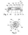
- a damper 101 which comprises a cylindrical housing 102, in which a piston 104 is displaceably guided on a piston rod 103.
- a sealing ring 105 is received in a groove.
- the groove in this case has a width which is greater than the cross section of the sealing ring 105, so that it is pressed at too high pressure from the inner wall of the housing 102 in the groove can be to avoid too high frictional forces when moving the piston 104.
- a plate 106 Adjacent to the piston 104, a plate 106 is fixed to one end of the piston rod 103 or to an extension of the piston 104.
- a balance piston is received in the housing 102, which compensates for a volume change due to the movement of the piston rod 103.
- the balance piston comprises a sealing ring 107, which is arranged on a retaining ring 111.
- the sealing ring 107 provides a seal to an inner space 108 in the housing 102, wherein the sealing ring 107 has an outer sealing lip 112 which rests against the inside of the housing 102, and has an inner sealing lip 113 which bears against the piston rod 103.
- the seal 107 can simultaneously provide a seal on the piston rod 103 as well as on the housing 102.
- the seal 107 and the retaining ring 111 are biased by a spring 110 which abuts against the retaining ring 111 and on the opposite side to a cover 109.
- the cover 109 is only latched to the housing 102, since the forces due to the spring 110 are low.
- a locking element 115 is fixed via a detent 116 to a groove or embossment which forms a partially open eyelet 117, so that another component, such as a furniture hinge can be snapped over the legs on the eyelet 117, so a simple Assembly is possible.
- the latching element 115 does not detach from the piston rod 103, as a pulling out of the piston rod 103 is smooth and the holding forces of the individual latching means are greater than the counteracting forces when pulling out the piston rod 103.
- the latching lugs 116 may be provided on the piston rod 103 an embossing , so that no machining of the piston rod 103 is required.
- the piston rod 103 made of metal or plastic can be made very thin in diameter, preferably in a range between 1.5 mm to 3.5 mm, in particular 2.0 mm to 3.0 mm. As a result, only a small volume compensation is required when retracting and extending the piston rod 103.
- the damper 101 is designed as a pressure damper, in which the force for retracting the piston rod 103 is at least five times, preferably eight to twelve times greater than the force for pulling out the piston rod 103.
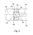
- a flow channel 120 is formed, which is partially formed by two diametrically opposite to the axis of the piston rod 103 radial grooves 160.
- the outer diameter of the plate 106 is smaller than the diameter of the piston 104.
- an opening 121 is recessed centrally, so that the plate 106 can be plugged onto a pin-shaped end 119 of the piston rod 103 or the piston 104.
- the pin-shaped end 119 is then deformed, so that the plate is held securely on the piston 104.
- a deformed end 119 ' is illustrated which fixes the plate 106 to the piston 104 instead of the piston rod 103, although other attachment mechanisms may be employed.
- one or more passage channels 122 are formed, which extend parallel to the axis of the piston rod 103.
- the plate 106 bends away from the piston 104 until, for example, the position 106 'is reached and the grooves 160 are spaced from the plate 106 and the fluid can flow from the inner space 108 through the passageways 122 to the inner space 123, without necessarily passing through the grooves 160.
- the plate is formed bendable and consists for example of plastic, preferably of a plastic film PET, so that after movement of the piston rod 103, the plate 106 moves back to the position adjacent to the piston 104 perpendicular to the axis of the piston rod 103.
- the housing 102 has on one side an outwardly open eyelet 118, wherein on the opposite side of the outwardly open eyelet 117 of the locking element 115 can be seen on the piston rod 103. Both eyelets 117 and 118 allow easy and quick assembly of the damper 101st
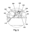
- FIG. 5 is a in the region of a piston 204 with respect to the embodiment of FIG. 1 shown slightly modified embodiment.
- the piston 204 is slidable in a cylindrical housing 202 of the damper.
- the piston 204 is fixed via a detent or bayonet connection to a piston rod 203 and has at least one axial flow channel 222.
- On the outer circumference of the piston 204 a groove is provided in which a formed as an O-ring sealing ring 205 is inserted, so that on opposite sides of the piston 204 formed chambers 223 and 224 via the piston 204 and the sealing ring 205 are separated from each other.
- a slotted support ring 209 Adjacent to the sealing ring 205, a slotted support ring 209 made of a rigid material, such as plastic or metal is inserted in the groove, which avoids a displacement of the sealing ring 205 in the groove and the sealing ring 205 can also compress in the axial direction. Because at high pressures, the sealing ring 205 can otherwise slip in the groove so that sufficient tightness is no longer guaranteed and the damper is no longer functional.
- a plate 206 is provided on the piston 204, which is axially secured to a cylindrical extension 210 by a snap ring 207.
- the plate 206 is held with axial clearance between the snap ring 207 and a side surface 208 of the piston 204, so that upon movement of the piston 204, the plate 206 abuts either the side surface 208 or the snap ring 207, and thus as in the previous embodiments Flow channel in the range of radial grooves on the plate 206 and / or on the side surface 208 is increased or decreased.
- the fluid used for the dampers shown is preferably an oil, in particular silicone oil, but also other fluids can be used for damping.
Abstract
Description
Die vorliegende Erfindung betrifft einen Dämpfer für Möbel, insbesondere für Scharniere, mit einem Gehäuse, in dem ein mit einer Kolbenstange verbundener Kolben verschiebbar aufgenommen ist, wobei ein Fluid bei einer Bewegung des Kolbens innerhalb des Gehäuses durch einen Strömungskanal am oder im Kolben strömt, wobei bei Bewegung des Kolbens in unterschiedliche Richtungen eine unterschiedliche Dämpfungskraft erhalten wird.The present invention relates to a damper for furniture, in particular for hinges, comprising a housing in which a piston connected to a piston rod is slidably received, wherein a fluid flows during a movement of the piston within the housing through a flow channel on or in the piston upon movement of the piston in different directions a different damping force is obtained.
Es gibt Dämpfer für Möbel, bei denen in einem Kolben eine Mikrobohrung angeordnet ist, sodass ein Fluid bei Bewegung des Kolbens von einer Seite des Kolbens zur anderen strömen kann, so dass die Bewegung des Kolbens durch das Fluid gedämpft ist. Bei der Herstellung solcher Mikrobohrungen, die meist kleiner als 0,15 mm sind, besteht der Nachteil, dass der Herstellungsprozess zeitaufwendig ist, da einen hohe Genauigkeit gefordert wird und zudem die Werkzeuge einem hohen Verschleiß unterliegen. Bei geringen Maßabweichungen können die Dämpfungskräfte völlig unterschiedliche ausfallen. Zudem können Mikrobohrungen durch kleine Partikel leicht verstopfen. Daher ist der Einsatz von Schaumstoffelementen zum Volumenausgleich nicht möglich, da losgelöste kleine Partikel das System blockieren könnten. Schließlich wird bei kleinen Mikrobohrungen die Wand ausgewaschen, sodass sich der Durchmesser nach gewisser Zeit vergrößert. Dadurch ändern sich die Eigenschaften des Dämpfers.There are dampers for furniture in which a microbore is disposed in a piston so that fluid can flow from one side of the piston to the other as the piston moves, such that movement of the piston is damped by the fluid. In the production of such micro-bores, which are usually smaller than 0.15 mm, there is the disadvantage that the manufacturing process is time-consuming, since a high accuracy is required and also the tools are subject to high wear. With small deviations, the damping forces can be completely different. In addition, microbores can easily become clogged by small particles. Therefore, the use of foam elements for volume compensation is not possible because detached small particles could block the system. Finally, with small microbores, the wall is washed out so that the diameter increases after a certain time. This will change the characteristics of the damper.
Ferner sind Dämpfer bekannt, bei denen das Fluid über einen Ringspalt zwischen Kolben und Gehäusewand strömt. Auch hier haben geringste Maßabweichungen am Kolbendurchmesser oder beim Zylinderinnendurchmesser große Auswirkungen auf das Dämpfungsverhalten. Toleranzen können sich addieren und insbesondere kann bei Veränderung des Innendrucks sich die Gehäusewand aufbiegen und den Ringspalt vergrößern. Zudem können sich auch hier Verunreinigungen nachteilig auf das Dämpfungsverhalten auswirken.Furthermore, dampers are known in which the fluid flows through an annular gap between the piston and the housing wall. Here, too, the smallest deviations in the diameter of the piston or in the inner diameter of the cylinder have a major effect on the damping behavior. Tolerances can add up and, in particular, the housing wall can bend when the internal pressure changes and increase the annular gap. In addition, impurities can also adversely affect the damping behavior here.
Aus der
Aus der
Die
Die
Es ist daher Aufgabe der vorliegenden Erfindung, einen Dämpfer für Möbel zu schaffen, der in der Benutzung unempfindlich ist und individuell an den jeweiligen Einsatzzweck relativ genau angepasst werden kann.The
The
It is therefore an object of the present invention to provide a damper for furniture that is insensitive to use and can be adapted to the particular application relatively accurately.
Diese Aufgabe wird mit einem Dämpfer mit den Merkmalen des Anspruches 1 gelöst.This object is achieved with a damper with the features of claim 1.
Der Querschnitt des Strömungskanals ist bereichsweise veränderbar, indem der Kolben relativ zu einer Platte bewegbar ist, wobei die Platte und/oder der Kolben sich radial erstreckende Nuten aufweist, die zumindest einen Teil des Strömungskanals bilden. Dadurch kann der Querschnitt des Strömungskanals relativ genau vorgegeben werden, wobei die an dem Kolben gelagerte Platte leicht herstellbar ist und sich bei Bedarf auch auswechseln lässt. Zudem kann der Dämpfer auf einfache Weise auf den jeweiligen Einsatzzweck eingestellt werden, da die Dämpfungskraft hauptsächlich von der Gestaltung des Strömungskanals am oder im Kolben abhängt, insbesondere vom Strömungsquerschnitt der radialen Nuten, die nicht nur eine Blende bilden, sondern von dem Fluid über eine gewisse Wegstrecke durchströmt werden. Diese Wegstrecke der radialen Nut kann vollständig zur Erzeugung von Reibungskräften und damit für einen Druckabfall des Fluides verwendet werden, was dann die Dämpfung bewirkt. Zudem lassen sich die Nuten wesentlich einfacher herstellen als Bohrungen durch Bohrwerkzeuge, da dabei Grate entstehen können, oder Öffnungen im Spritzgussverfahren, bei denen Spritzgusshäute gebildet werden können. Durch die Veränderung des Strömungskanals zwischen der Platte und dem Kolben kann sich diese zudem weniger leicht durch Verschmutzungen zusetzen, da Teile durch die Veränderung des Querschnittes nicht so leicht einklemmen können.The cross section of the flow channel is partially variable by the piston is movable relative to a plate, wherein the plate and / or the piston has radially extending grooves which form at least part of the flow channel. As a result, the cross-section of the flow channel can be specified relatively accurately, wherein the plate mounted on the piston is easy to produce and can be replaced if necessary. In addition, the damper can be easily adjusted to the particular application, since the damping force mainly on the design of the flow channel on or depends in the piston, in particular from the flow cross-section of the radial grooves, which not only form a diaphragm, but are traversed by the fluid over a certain distance. This distance of the radial groove can be completely used to generate frictional forces and thus a pressure drop of the fluid, which then causes the damping. In addition, the grooves can be much easier to produce than drilling by drilling tools, since this can cause burrs, or openings in the injection molding process, in which injection molded skins can be formed. By changing the flow channel between the plate and the piston, this can also be less easily clogged by contamination, as parts can not pinch so easily by the change in the cross section.
Auf einer Seite des Gehäuses ist erfindungsgemäß ein bewegbarer Ausgleichskolben vorgesehen, der abgedichtet an dem Gehäuse und der Kolbenstange geführt ist. Durch den Ausgleichskolben kann eine Volumenveränderung durch die Bewegung der Kolbenstange kompensiert werden. Der Ausgleichskolben weist eine Dichtung auf oder besteht aus einer Dichtung, wobei die Dichtung mit einer äußeren Dichtlippe am Gehäuse und mit einer inneren Dichtlippe an der Kolbenstange anliegt, so dass nur eine einzige Dichtung notwendig ist. Ferner kann der Ausgleichskolben vorzugsweise durch eine Feder zu dem Innenraum mit dem Kolben hin vorgespannt sein, die einen leichten Innendruck in dem Gehäuse erzeugt. Dabei kann die Feder an einem Deckel abgestützt sein, der an dem Gehäuse festgelegt ist und von der Kolbenstange durchgriffen ist, so dass ein einfach zu montierender Aufbau gegeben ist.On one side of the housing, a movable compensating piston is provided according to the invention, which is sealingly guided on the housing and the piston rod. By the balance piston, a change in volume can be compensated by the movement of the piston rod. The balance piston has a seal or consists of a seal, wherein the seal with an outer sealing lip on the housing and with an inner sealing lip rests against the piston rod, so that only a single seal is necessary. Further, the balance piston may preferably be biased by a spring toward the interior with the piston creating a slight internal pressure in the housing. In this case, the spring may be supported on a cover, which is fixed to the housing and is penetrated by the piston rod, so that an easy-to-install construction is given.
Gemäß einer bevorzugten Ausgestaltung der Erfindung sind der Kolben und die Platte gemeinsam auf einer Kolbenstange gelagert. Zur Veränderung des Querschnitt des Strömungskanals kann der Kolben in axiale Richtung bewegt werden, so dass ein radialer Abschnitt zwischen Kolben und Platte eine Art Ventilfunktion besitzt und die Bewegung des Kolbens in einer Richtung stärker gedämpft ist als in die gegenüberliegende Richtung. Dies ist insbesondere bei Möbeln ein Vorteil, da die Öffnungsbewegung leichtgängig erfolgen soll, aber beim Schließen eine Dämpfung von Vorteil ist. Die Dämpfungskraft kann in die gegenüberliegenden Bewegungsrichtungen des Kolbens um einen Faktor größer 5, vorzugsweise um einen Faktor 8 bis 12 unterschiedlich sein.According to a preferred embodiment of the invention, the piston and the plate are mounted together on a piston rod. To change the cross-section of the flow channel, the piston can be moved in the axial direction, so that a radial portion between the piston and plate has a kind of valve function and the movement of the piston is more damped in one direction than in the opposite direction. This is an advantage especially in furniture, since the opening movement should be smooth, but when closing a damping is beneficial. The damping force can in the opposite directions of movement of the piston by a factor greater than 5, preferably be different by a factor of 8 to 12.
Vorzugsweise ist die Platte an der Kolbenstange festgelegt und der Kolben mit Spiel an der Kolbenstange gehalten. Dadurch kann mit wenigen Bauteilen ein Dämpfer bereitgestellt werden, bei dem der Strömungskanal verändert werden kann. Der Kolben kann dabei die Kolbenstange ringförmig umgeben und zwischen einer Platte und einer Schulter an der Kolbenstange bewegbar gehalten sein. Dadurch kann der Strömungskanal zwischen Kolben und Kolbenstange konstant bleiben, beispielsweise können entsprechende Ausnehmungen an einer ansonsten zylindrischen Aufnahme des Kolben vorgesehen sein. Aufgrund des axialen Spiels des Kolbens wird dann ein in radiale Richtung verlaufender Abschnitt des Strömungskanals im Querschnitt verändert. Dort kann dann der engste Querschnitt des Strömungskanals gebildet sein, der für die Drosseleigenschaften relevant ist. Die radialen Nuten sind dabei vorzugsweise so angeordnet, dass jeweils zwei diametral zur Kolbenachse gegenüberliegende Nuten vorgesehen sind. Dies gewährleistet eine gleichmäßige Dämpfungskraft und verhindert mögliche Querkräfte in radialer Richtung, die für ein Verklemmen des Kolbens sorgen könnten.Preferably, the plate is fixed to the piston rod and the piston held with play on the piston rod. This can be provided with few components, a damper, in which the flow channel can be changed. The piston can thereby surround the piston rod annularly and be movably held between a plate and a shoulder on the piston rod. Thereby, the flow channel between the piston and piston rod remain constant, for example, corresponding recesses may be provided on an otherwise cylindrical receptacle of the piston. Due to the axial play of the piston, a section of the flow channel extending in the radial direction is then changed in cross section. There then the narrowest cross-section of the flow channel may be formed, which is relevant to the throttle characteristics. The radial grooves are preferably arranged so that in each case two diametrically opposite to the piston axis grooves are provided. This ensures a uniform damping force and prevents possible transverse forces in the radial direction, which could cause jamming of the piston.
Gemäß einer weiteren Ausgestaltung der Erfindung ist die Platte an einer topfförmigen Aufnahme des Kolbens angeordnet.According to a further embodiment of the invention, the plate is arranged on a cup-shaped receptacle of the piston.
Gemäß einer weiteren Ausführungsform ist zur Veränderung des Querschnitts des Strömungskanals der Kolben fest und die Platte biegbar ausgebildet. Dadurch kann der Dämpfer auf einfache Weise als Druckdämpfer ausgebildet sein, der beim Eindrücken der Kolbenstange in das Gehäuse schwergängig ist, während ein Herausziehen der Kolbenstange vergleichsweise leichtgängig erfolgen kann. Die Platte kann dabei als Scheibe aus Kunststoff, vorzugsweise aus einer Kunststofffolie, gebildet sein, da die Beanspruchung der Scheibe auch im Bereich des Strömungskanals relativ gering ist.According to a further embodiment, the piston is fixed and the plate bendable to change the cross section of the flow channel. As a result, the damper can be designed in a simple manner as a pressure damper, which is stiff when the piston rod is pressed into the housing, while the piston rod can be pulled out relatively easily. The plate can be formed as a disc made of plastic, preferably from a plastic film be, since the stress of the disc is relatively low in the region of the flow channel.
Wenn der Dämpfer als Druckdämpfer ausgebildet ist, können an der Kolbenstange und/oder dem Gehäuse Rastmittel, vorzugsweise mit biegbaren Schenkeln, zum Verbinden mit einem weiteren Bauteil vorgesehen sein, da die Zugbelastungen bei der Bewegung der Kolbenstange geringer sind als die Haltekräfte der Rastmittel, so dass der Dämpfer einfach und schnell montiert und auch nachgerüstet werden kann.If the damper is designed as a pressure damper, can be provided on the piston rod and / or the housing locking means, preferably with bendable legs, for connection to another component, since the tensile loads during the movement of the piston rod are smaller than the holding forces of the locking means, so that the damper can be easily and quickly mounted and retrofitted.
Die Erfindung wird nachfolgend anhand von mehreren Ausführungsbeispielen mit Bezug auf die beigefügten Zeichnungen näher erläutert. Es zeigen:
- Figur 1
- eine teilweise geschnittene Seitenansicht einer Ausfüh- rungsform eines Dämpfers;
- Figur 2
- eine perspektivische Detailansicht des Dämpfers der Figur 10;
- Figur 3
- eine schematische Ansicht des Dämpfers der Figur 10 im Bereich des Kolbens;
- Figur 4A und 4B
- zwei Ansichten des Dämpfers der
Figur 1 ; - Figur 6
- eine Detailansicht eines zu dem Ausführungsbeispiel der
Figur 1 modifizierten Dämpfers.
- FIG. 1
- a partially sectioned side view of an embodiment of a damper;
- FIG. 2
- a detailed perspective view of the damper of Figure 10;
- FIG. 3
- a schematic view of the damper of Figure 10 in the region of the piston;
- FIGS. 4A and 4B
- two views of the damper the
FIG. 1 ; - FIG. 6
- a detailed view of one of the embodiment of the
FIG. 1 modified damper.
Bei der in den
Benachbart zu dem Kolben 104 ist an einem Ende der Kolbenstange 103 oder an einem Fortsatz des Kolbens 104 eine Platte 106 fixiert. An der gegenüberliegenden Seite des Kolbens 104 ist ein Ausgleichskolben in dem Gehäuse 102 aufgenommen, der eine Volumenänderung aufgrund des Bewegens der Kolbenstange 103 kompensiert. Der Ausgleichskolben umfasst einen Dichtring 107, der an einem Haltering 111 angeordnet ist. Der Dichtring 107 stellt eine Abdichtung zu einem Innenraum 108 in dem Gehäuse 102 her, wobei der Dichtring 107 eine äußere Dichtlippe 112 besitzt, die an der Innenseite des Gehäuses 102 anliegt, sowie eine innere Dichtlippe 113 besitzt, die an der Kolbenstange 103 anliegt. Dadurch kann die Dichtung 107 gleichzeitig eine Abdichtung an der Kolbenstange 103 als auch an dem Gehäuse 102 bereitstellen.Adjacent to the
Die Dichtung 107 und der Haltering 111 sind über eine Feder 110 vorgespannt, die an dem Haltering 111 und an der gegenüberliegenden Seite an einem Deckel 109 anliegt. Der Deckel 109 ist dabei nur rastend an dem Gehäuse 102 festgelegt, da die Kräfte aufgrund der Feder 110 gering sind.The
An der Kolbenstange 103 ist ein Rastelement 115 über eine Rastnase 116 an einer Nut oder Verprägung fixiert, das eine teilweise offene Öse 117 ausbildet, so dass ein weiteres Bauteil, beispielsweise eines Möbelscharniers über die Schenkel an der Öse 117 eingerastet werden kann, also eine einfach Montage möglich ist. Das Rastelement 115 löst sich nicht von der Kolbenstange 103, da ein Herausziehen der Kolbenstange 103 leichtgängig erfolgt und die Haltekräfte der einzelnen Rastmittel größer sind als die entgegenwirkenden Kräfte beim Herausziehen der Kolbenstange 103. Für die Rastnasen 116 kann an der Kolbenstange 103 eine Verprägung vorgesehen sein, so dass keine spanende Bearbeitung der Kolbenstange 103 erforderlich ist. Dadurch kann die aus Metall oder Kunststoff bestehenden Kolbenstange 103 im Durchmesser sehr dünn ausgebildet sein, vorzugsweise in einem Bereich zwischen 1,5mm bis 3,5 mm, insbesondere 2,0 mm bis 3,0 mm. Dadurch wird bei Ein- und Ausfahren der Kolbenstange 103 nur ein geringer Volumenausgleich notwendig.On the
Der Dämpfer 101 ist als Druckdämpfer ausgebildet, bei dem die Kraft zum Einfahren der Kolbenstange 103 mindestens fünfinal, vorzugsweise acht bis zwölf mal größer ist als die Kraft zum Herausziehen der Kolbenstange 103.The
Zwischen dem Kolben 104 und der ringförmigen Platte 106 ist ein Strömungskanal 120 ausgebildet, der abschnittsweise durch zwei sich diametral zur Achse der Kolbenstange 103 gegenüberliegende radiale Nuten 160 gebildet ist. Der äußere Durchmesser der Platte 106 ist dabei geringer als der Durchmesser des Kolbens 104. In der Platte 106 ist eine Öffnung 121 mittig ausgespart, so dass die Platte 106 auf ein zapfenförmiges Ende 119 der Kolbenstange 103 oder des Kolbens 104 aufgesteckt werden kann. Zur Fixierung der Platte 106 wird dann das zapfenförmige Ende 119 verformt, so dass die Platte sicher an dem Kolben 104 gehalten ist.Between the
In
Wird an der Kolbenstange 103 gezogen (untere Hälfte der
In den
In
Auf der Seite der Kammer 223 ist an dem Kolben 204 eine Platte 206 vorgesehen, die an einem zylindrischen Fortsatz 210 durch einen Sprengring 207 axial gesichert ist. Die Platte 206 ist mit axialem Spiel zwischen dem Sprengring 207 und einer Seitenfläche 208 des Kolbens 204 gehalten, so dass bei einer Bewegung des Kolbens 204 die Platte 206 entweder an der Seitenfläche 208 oder am Sprengring 207 anliegt, und somit wie bei den vorangegangenen Ausführungsbeispielen ein Strömungskanal im Bereich von radialen Nuten an der Platte 206 und/oder an der Seitenfläche 208 vergrößert oder verkleinert wird.On the side of the
Als Fluid wird für die gezeigten Dämpfer vorzugsweise ein Öl, insbesondere Silikonöl, eingesetzt, aber auch andere Fluide können zur Dämpfung verwendet werden.The fluid used for the dampers shown is preferably an oil, in particular silicone oil, but also other fluids can be used for damping.
Claims (17)
- Damper (101) for furniture, in particular for hinges, with a housing (102, 202) in which a piston (104, 204), which is connected to a piston rod (103, 203), is displaceably accommodated, wherein, upon movement of the piston (104, 204) within the housing (102, 202), a fluid flows through a flow channel (120) on or in the piston (104, 204), and wherein, upon movement of the piston (104, 204) in different directions, a different damping force is obtained and the cross section of the flow channel (120) can be changed in regions by the piston (104, 204) being movable relative to a plate (106, 206) and the plate (106, 206) and/or the piston (104, 204) having radially extending grooves (160) which form at least part of the flow channel (120), characterized in that a movable compensating piston (107, 111) is provided on one side of the housing (102), said compensating piston being guided in a sealed manner on the housing (102) and the piston rod (103) and having a seal (107) which bears with an outer sealing lip (112) against the housing (102) and with an inner sealing lip (113) against the piston rod (103).
- Damper according to Claim 1, characterized in that the piston (104, 204) and the plate (106, 206) are mounted together on the piston rod (103, 203).
- Damper according to Claim 2, characterized in that the plate is fixed to the piston rod, and the piston is held with axial play on the piston rod.
- Damper according to Claim 2 or 3, characterized in that the piston annularly surrounds the piston rod and is held movably between the plate and a shoulder on the piston rod.
- Damper according to Claim 2, characterized in that the piston (204) is fixed to the piston rod (203), and the plate (206) is held with axial play on the piston rod (203) or the piston (204).
- Damper according to one of Claims 1-5, characterized in that the radial flow channel (120) along the grooves (160) is the narrowest part of the flow channel with the plate (106, 206) bearing against the piston (104, 204).
- Damper according to one of Claims 1-6, characterized in that two grooves (160) which are opposite each other diametrically with respect to the piston axis are in each case provided.
- Damper according to one of Claims 1-7, characterized in that the plate is arranged on a cup-shaped receptacle of the piston.
- Damper according to one of Claims 1-8, characterized in that the piston has a cylindrical receptacle for the piston rod, and at least one recess for forming a flow channel is provided on the receptacle.
- Damper according to one of Claims 1-9, characterized in that, in order to change the cross section of the flow channel (120), the plate (106) is designed to be bendable.
- Damper according to Claim 10, characterized in that the plate (106) is formed as a disc made of plastic, preferably made of a plastics sheet.
- Damper according to one of Claims 1-11, characterized in that the compensating piston comprises a seal (107) which is supported by a retaining ring (111).
- Damper according to one of Claims 1-12, characterized in that the compensating piston (107, 111) is prestressed towards the interior space with the piston (104) by a spring (110).
- Damper according to Claim 13, characterized in that the spring (110) is supported on a cover (109) which is fixed to the housing (102) and through which the piston rod (103) reaches.
- Damper according to one of Claims 1-14, characterized in that latching means (115), preferably with bendable limbs, are provided on the piston rod (103) with a connection to a further component.
- Damper according to one of Claims 1-15, characterized in that the force for moving the piston (104, 204) in opposite directions differs by a factor of 5, preferably by a factor of 8 to 12.
- Damper according to one of Claims 1-16, characterized in that the outside of the piston (204) has a groove with a sealing ring (205) for separating the chambers (223, 224) arranged on both sides of the piston (204), and a slotted supporting ring (209) made of a stiff material is fitted in the groove.
Priority Applications (1)
| Application Number | Priority Date | Filing Date | Title |
|---|---|---|---|
| EP08164908A EP2006480B1 (en) | 2006-03-01 | 2007-02-27 | Damper for furniture |
Applications Claiming Priority (2)
| Application Number | Priority Date | Filing Date | Title |
|---|---|---|---|
| DE202006003197U DE202006003197U1 (en) | 2006-03-01 | 2006-03-01 | Damper for furniture |
| PCT/EP2007/051849 WO2007099100A2 (en) | 2006-03-01 | 2007-02-27 | Damper for furniture |
Related Child Applications (2)
| Application Number | Title | Priority Date | Filing Date |
|---|---|---|---|
| EP08164908A Division EP2006480B1 (en) | 2006-03-01 | 2007-02-27 | Damper for furniture |
| EP08164908.9 Division-Into | 2008-09-23 |
Publications (2)
| Publication Number | Publication Date |
|---|---|
| EP2010741A2 EP2010741A2 (en) | 2009-01-07 |
| EP2010741B1 true EP2010741B1 (en) | 2011-08-10 |
Family
ID=38017052
Family Applications (2)
| Application Number | Title | Priority Date | Filing Date |
|---|---|---|---|
| EP08164908A Active EP2006480B1 (en) | 2006-03-01 | 2007-02-27 | Damper for furniture |
| EP07712338A Active EP2010741B1 (en) | 2006-03-01 | 2007-02-27 | Damper for furniture |
Family Applications Before (1)
| Application Number | Title | Priority Date | Filing Date |
|---|---|---|---|
| EP08164908A Active EP2006480B1 (en) | 2006-03-01 | 2007-02-27 | Damper for furniture |
Country Status (10)
| Country | Link |
|---|---|
| EP (2) | EP2006480B1 (en) |
| JP (1) | JP5270376B2 (en) |
| KR (1) | KR101508482B1 (en) |
| CN (1) | CN101395333B (en) |
| AT (1) | ATE519911T1 (en) |
| DE (1) | DE202006003197U1 (en) |
| ES (2) | ES2401528T3 (en) |
| RU (1) | RU2425941C2 (en) |
| TW (1) | TWI387691B (en) |
| WO (1) | WO2007099100A2 (en) |
Families Citing this family (23)
| Publication number | Priority date | Publication date | Assignee | Title |
|---|---|---|---|---|
| DE202007011194U1 (en) | 2007-08-10 | 2008-12-24 | Hettich-Oni Gmbh & Co. Kg | hinge |
| DE202008011190U1 (en) * | 2008-08-22 | 2009-12-31 | Hettich-Oni Gmbh & Co. Kg | Hinge and tool for disassembling a linear damper from a hinge |
| DE202009004751U1 (en) | 2009-04-28 | 2010-09-09 | Druck- und Spritzgußwerk Hettich GmbH & Co. KG | Damper for furniture |
| DE202009004752U1 (en) | 2009-04-28 | 2010-09-09 | Druck- und Spritzgußwerk Hettich GmbH & Co. KG | Damper for furniture |
| IT1398554B1 (en) | 2010-03-08 | 2013-03-01 | Guiros S P A Ora Guiros S R L | SHOCK |
| AT510375B1 (en) | 2010-08-27 | 2018-06-15 | Blum Gmbh Julius | FURNITURE SHOCKS |
| DE102011122220A1 (en) * | 2011-12-23 | 2013-06-27 | Grass Gmbh | Damping device for use in furniture fitting of movable furniture part e.g. drawer, has damper link moveably linked to furniture part, where kinetic energy of link is absorbed by damping fluid containing damping liquid and emulsifying agent |
| DE102013001650B4 (en) * | 2013-01-31 | 2015-07-23 | Günther Zimmer | Cylinder-piston unit with piston throttle |
| ITMI20130344A1 (en) | 2013-03-07 | 2014-09-08 | Brera Cerniere Srl | FLUID SHOCK ABSORBER, PARTICULARLY FOR HOUSEHOLD APPLIANCES SUCH AS OVENS, DISHWASHER OR SIMILAR OR FOR FURNISHING COMPONENTS SUCH AS DOORS OR DRAWERS, SIMPLY EASY TO REALIZE. |
| AT514663B1 (en) * | 2013-07-18 | 2015-05-15 | Blum Gmbh Julius | Damper for movable furniture parts |
| TWI596287B (en) * | 2013-07-26 | 2017-08-21 | Damper | |
| CN103615494A (en) * | 2013-11-29 | 2014-03-05 | 常州大学 | Damper used for vibration reduction of pipeline |
| CN104653686B (en) * | 2015-02-06 | 2017-02-01 | 伍志勇 | Buffer with controllable buffering force |
| DE102015015170B3 (en) * | 2015-11-26 | 2016-12-15 | Günther Zimmer | Cylinder-piston unit with compensating sealing element |
| DE102017114475A1 (en) | 2017-06-29 | 2019-01-03 | Druck- und Spritzgußwerk Hettich GmbH & Co. KG | damper |
| AT520128A1 (en) * | 2017-07-13 | 2019-01-15 | Blum Gmbh Julius | furniture damper |
| WO2019025568A1 (en) | 2017-08-02 | 2019-02-07 | Wolfgang Held | Fluid damper for bodies that are movable relative to one another, comprising a piston that is movably guided in a cylinder. |
| DE102017010876B4 (en) | 2017-11-24 | 2023-06-01 | Günther Zimmer | Cylinder-piston unit with load-dependent throttle |
| EP3740426A4 (en) * | 2018-01-17 | 2021-09-22 | Adams Rite Aerospace Inc. | Shock absorber configured with a deformable energy absorbing member |
| DE202018103637U1 (en) | 2018-06-26 | 2019-09-27 | Druck- und Spritzgußwerk Hettich GmbH & Co. KG | damper |
| KR101978611B1 (en) * | 2018-11-22 | 2019-08-28 | 변용근 | Soft damper |
| CN110006741B (en) * | 2019-04-10 | 2020-07-03 | 浙江大学 | Buffer device for capturing high-temperature flying-off sample in supergravity environment |
| WO2023101622A1 (en) * | 2021-12-01 | 2023-06-08 | Samet Kalip Ve Madeni̇ Eşya San Ve Ti̇c. A.Ş | A hydraulic damper for furniture doors and drawers |
Citations (1)
| Publication number | Priority date | Publication date | Assignee | Title |
|---|---|---|---|---|
| US4881723A (en) * | 1985-08-03 | 1989-11-21 | Fritz Bauer + Sohne Ohg | Double-damped gas spring with friction liner and sealing ring |
Family Cites Families (31)
| Publication number | Priority date | Publication date | Assignee | Title |
|---|---|---|---|---|
| DE207033C (en) * | ||||
| DE476042C (en) * | 1929-05-07 | Ernst Kunze Jr | Liquid shock absorbers, especially for motor vehicles | |
| US1028400A (en) * | 1910-08-08 | 1912-06-04 | Horace B Stanton | Shock-absorber. |
| DE545334C (en) * | 1929-10-20 | 1932-02-29 | Ernst Wagner Appbau | Fluid brake, especially for carts with a lifting platform |
| DE899302C (en) * | 1942-01-03 | 1953-12-10 | Hemscheidt Maschf Hermann | Overpressure valve, especially for liquid shock absorbers of motor vehicles |
| DE2364855A1 (en) * | 1973-12-28 | 1975-07-03 | Weisser Ulfried Dipl Volksw | Shock absorber for motor vehicles - has working cylinder with two oil filled chambers controlled by two spring loaded valves |
| DE2623873A1 (en) * | 1976-05-28 | 1977-12-15 | Volkswagenwerk Ag | Pressurised support for vehicle boot lid - has piston and sliding seal loaded with compression spring |
| DE20221550U1 (en) * | 1977-02-03 | 2006-05-11 | Julius Blum Gmbh | Fluid damper especially for movable parts of furniture has piston with several spaced apart annular discs with orifices for damping fluid and in part elastically bendable to cover orifices of disc below during piston's damping stroke |
| JPS603406Y2 (en) * | 1978-02-28 | 1985-01-30 | 松下電工株式会社 | Sliding door damper device |
| JPS6016029U (en) * | 1983-07-14 | 1985-02-02 | 株式会社 ニフコ | Piston cylinder type damper |
| DE3326275A1 (en) * | 1983-07-21 | 1984-02-02 | Anna Dorothea 8000 München Sapunarow-Ryffel | Hydraulic single-tube shock absorber having a variable damping level |
| DE3513839A1 (en) * | 1985-04-17 | 1986-10-23 | Fritz Bauer + Söhne oHG, 8503 Altdorf | FLUID FILLED PUMP CYLINDER UNIT |
| DE3671777D1 (en) * | 1985-08-29 | 1990-07-12 | Airax Sa | DEVICE FOR OPENING AND CLOSING BUILDING OPENINGS BY SPRING. |
| JPS63167137A (en) * | 1986-12-29 | 1988-07-11 | Fuji Seiki Kk | Shock absorber |
| DE3741712A1 (en) * | 1987-12-09 | 1989-06-22 | Hettich Paul Gmbh & Co | FURNITURE HINGE |
| DE9114400U1 (en) * | 1991-11-19 | 1992-02-06 | Haber, Horst, Dipl.-Ing., 6781 Ruppertsweiler, De | |
| JPH0552385U (en) * | 1991-12-24 | 1993-07-13 | エヌオーケー株式会社 | Sealing device for shock absorber |
| GB9215897D0 (en) * | 1992-07-25 | 1992-09-09 | Weatherley Richard M | Model car shock absorbers |
| JPH0678641U (en) * | 1993-04-15 | 1994-11-04 | エヌオーケー株式会社 | Piston and damper using it |
| JPH0685942U (en) * | 1993-05-25 | 1994-12-13 | エヌオーケー株式会社 | Piston and damper using it |
| US5927448A (en) * | 1996-03-15 | 1999-07-27 | Fuji Seiki Kabushiki Kaisha | Shock absorber |
| JPH10311358A (en) * | 1997-05-07 | 1998-11-24 | Ckd Corp | Shock absorber |
| JPH11325152A (en) * | 1998-05-19 | 1999-11-26 | Matsushita Electric Ind Co Ltd | Damper device |
| DE10054904A1 (en) * | 2000-11-06 | 2002-05-16 | Grass Gmbh Hoechst | Braking and damping element has piston in cylinder, valve arrangement of sliding valve and seal, compression chamber, and piston pin. |
| DE20022202U1 (en) * | 2000-12-28 | 2001-08-30 | Hydrostat Gmbh Stosdaempfer Un | Hydraulic shock absorber with maximum force limitation |
| AT414033B (en) * | 2001-01-09 | 2006-08-15 | Blum Gmbh Julius | DAMPERS, ESPECIALLY FOR FURNITURE |
| DE20107426U1 (en) * | 2001-04-30 | 2001-08-30 | Zimmer Guenther Stephan | Brake controller with air or liquid damping, in particular for damping the end position of drawers, doors or the like. Facilities |
| JP2003336678A (en) * | 2002-05-22 | 2003-11-28 | Kayaba Ind Co Ltd | Gas spring |
| TW563464U (en) * | 2003-03-04 | 2003-11-21 | Nan Juen Int Co Ltd | Folding buffer device for drawer rail |
| JP2004347106A (en) * | 2003-05-22 | 2004-12-09 | Hyundai Motor Co Ltd | Damping force adjustable shock absorber |
| DE10343928B3 (en) * | 2003-09-20 | 2004-11-11 | Stabilus Gmbh | Ventilator spring for opening a flap, especially a trunk lid of a motor vehicle, comprises a propeller spring with both ends formed as hooks which interact in corresponding receivers on the free end of a piston rod |
-
2006
- 2006-03-01 DE DE202006003197U patent/DE202006003197U1/en not_active Expired - Lifetime
-
2007
- 2007-02-27 KR KR1020087023792A patent/KR101508482B1/en active IP Right Grant
- 2007-02-27 EP EP08164908A patent/EP2006480B1/en active Active
- 2007-02-27 CN CN2007800073104A patent/CN101395333B/en active Active
- 2007-02-27 ES ES08164908T patent/ES2401528T3/en active Active
- 2007-02-27 RU RU2008138611/12A patent/RU2425941C2/en active
- 2007-02-27 WO PCT/EP2007/051849 patent/WO2007099100A2/en active Application Filing
- 2007-02-27 JP JP2008556769A patent/JP5270376B2/en active Active
- 2007-02-27 EP EP07712338A patent/EP2010741B1/en active Active
- 2007-02-27 ES ES07712338T patent/ES2370944T3/en active Active
- 2007-02-27 AT AT07712338T patent/ATE519911T1/en active
- 2007-03-01 TW TW096106935A patent/TWI387691B/en active
Patent Citations (1)
| Publication number | Priority date | Publication date | Assignee | Title |
|---|---|---|---|---|
| US4881723A (en) * | 1985-08-03 | 1989-11-21 | Fritz Bauer + Sohne Ohg | Double-damped gas spring with friction liner and sealing ring |
Also Published As
| Publication number | Publication date |
|---|---|
| CN101395333B (en) | 2012-11-14 |
| WO2007099100A2 (en) | 2007-09-07 |
| CN101395333A (en) | 2009-03-25 |
| EP2006480A1 (en) | 2008-12-24 |
| JP5270376B2 (en) | 2013-08-21 |
| RU2008138611A (en) | 2010-04-10 |
| TWI387691B (en) | 2013-03-01 |
| KR101508482B1 (en) | 2015-04-06 |
| ES2401528T3 (en) | 2013-04-22 |
| DE202006003197U1 (en) | 2007-07-12 |
| ES2370944T3 (en) | 2011-12-26 |
| JP2009528490A (en) | 2009-08-06 |
| TW200745459A (en) | 2007-12-16 |
| ATE519911T1 (en) | 2011-08-15 |
| KR20080102261A (en) | 2008-11-24 |
| EP2006480B1 (en) | 2012-12-19 |
| EP2010741A2 (en) | 2009-01-07 |
| WO2007099100A3 (en) | 2008-01-24 |
| RU2425941C2 (en) | 2011-08-10 |
Similar Documents
| Publication | Publication Date | Title |
|---|---|---|
| EP2010741B1 (en) | Damper for furniture | |
| EP2425080B1 (en) | Damper for furniture | |
| DE10112793B4 (en) | Hydraulic vibration damper | |
| DE102011089140B3 (en) | Vibration damper with a hydraulic end stop | |
| WO2021037798A1 (en) | Damping valve device having a progressive damping force characteristic curve | |
| DE3840302C2 (en) | Low-noise damping valve | |
| EP1717396B1 (en) | Abutment damper | |
| DE112019001540T5 (en) | Damping force generating mechanism and pressure shock absorber | |
| DE3008707A1 (en) | PISTON WITH PRESSURE-RELATED PRESSURE OF THE PISTON RING ON THE CYLINDER INTERNAL WALL | |
| DE10334032B4 (en) | valve means | |
| EP1121542A1 (en) | Piston with support webs for a piston-cylinder arrangement, especially a shock absorber piston | |
| EP2962022B1 (en) | Overflow valve | |
| DE102008042103A1 (en) | Vibration damper with amplitude-selective damping force | |
| EP3645818A1 (en) | Damper | |
| EP1923595B1 (en) | Vibration damper with amplitude-dependent damping force | |
| DE102018220654B4 (en) | Damping valve arrangement, in particular for a vibration damper | |
| EP1001196B1 (en) | Pressure limitting valve, especially for vehicles | |
| DE102013002452B4 (en) | Fluid technical device | |
| DE10026360B4 (en) | Piston rod guide | |
| EP2841793B1 (en) | Damper | |
| DE102009054121A1 (en) | damper valve | |
| DE112019006507T5 (en) | Shock absorbers | |
| WO2018197106A1 (en) | Sealing and guide arrangement | |
| DE19753506C2 (en) | Ring separating piston for a piston-cylinder unit | |
| WO2017045842A1 (en) | Damping valve for a vibration damper |
Legal Events
| Date | Code | Title | Description |
|---|---|---|---|
| PUAI | Public reference made under article 153(3) epc to a published international application that has entered the european phase |
Free format text: ORIGINAL CODE: 0009012 |
|
| 17P | Request for examination filed |
Effective date: 20080826 |
|
| AK | Designated contracting states |
Kind code of ref document: A2 Designated state(s): AT BE BG CH CY CZ DE DK EE ES FI FR GB GR HU IE IS IT LI LT LU LV MC NL PL PT RO SE SI SK TR |
|
| AX | Request for extension of the european patent |
Extension state: AL BA HR MK RS |
|
| RIN1 | Information on inventor provided before grant (corrected) |
Inventor name: ROMMELMANN, CORD Inventor name: BECKMANN, WOLFGANG |
|
| 17Q | First examination report despatched |
Effective date: 20091119 |
|
| GRAP | Despatch of communication of intention to grant a patent |
Free format text: ORIGINAL CODE: EPIDOSNIGR1 |
|
| GRAS | Grant fee paid |
Free format text: ORIGINAL CODE: EPIDOSNIGR3 |
|
| GRAA | (expected) grant |
Free format text: ORIGINAL CODE: 0009210 |
|
| DAX | Request for extension of the european patent (deleted) | ||
| AK | Designated contracting states |
Kind code of ref document: B1 Designated state(s): AT BE BG CH CY CZ DE DK EE ES FI FR GB GR HU IE IS IT LI LT LU LV MC NL PL PT RO SE SI SK TR |
|
| REG | Reference to a national code |
Ref country code: GB Ref legal event code: FG4D Free format text: NOT ENGLISH |
|
| REG | Reference to a national code |
Ref country code: CH Ref legal event code: EP |
|
| REG | Reference to a national code |
Ref country code: IE Ref legal event code: FG4D Free format text: LANGUAGE OF EP DOCUMENT: GERMAN |
|
| REG | Reference to a national code |
Ref country code: DE Ref legal event code: R096 Ref document number: 502007007904 Country of ref document: DE Effective date: 20111006 |
|
| REG | Reference to a national code |
Ref country code: NL Ref legal event code: T3 |
|
| REG | Reference to a national code |
Ref country code: ES Ref legal event code: FG2A Ref document number: 2370944 Country of ref document: ES Kind code of ref document: T3 Effective date: 20111226 |
|
| LTIE | Lt: invalidation of european patent or patent extension |
Effective date: 20110810 |
|
| PG25 | Lapsed in a contracting state [announced via postgrant information from national office to epo] |
Ref country code: FI Free format text: LAPSE BECAUSE OF FAILURE TO SUBMIT A TRANSLATION OF THE DESCRIPTION OR TO PAY THE FEE WITHIN THE PRESCRIBED TIME-LIMIT Effective date: 20110810 Ref country code: PT Free format text: LAPSE BECAUSE OF FAILURE TO SUBMIT A TRANSLATION OF THE DESCRIPTION OR TO PAY THE FEE WITHIN THE PRESCRIBED TIME-LIMIT Effective date: 20111212 Ref country code: LT Free format text: LAPSE BECAUSE OF FAILURE TO SUBMIT A TRANSLATION OF THE DESCRIPTION OR TO PAY THE FEE WITHIN THE PRESCRIBED TIME-LIMIT Effective date: 20110810 Ref country code: IS Free format text: LAPSE BECAUSE OF FAILURE TO SUBMIT A TRANSLATION OF THE DESCRIPTION OR TO PAY THE FEE WITHIN THE PRESCRIBED TIME-LIMIT Effective date: 20111210 Ref country code: SE Free format text: LAPSE BECAUSE OF FAILURE TO SUBMIT A TRANSLATION OF THE DESCRIPTION OR TO PAY THE FEE WITHIN THE PRESCRIBED TIME-LIMIT Effective date: 20110810 |
|
| PG25 | Lapsed in a contracting state [announced via postgrant information from national office to epo] |
Ref country code: CY Free format text: LAPSE BECAUSE OF FAILURE TO SUBMIT A TRANSLATION OF THE DESCRIPTION OR TO PAY THE FEE WITHIN THE PRESCRIBED TIME-LIMIT Effective date: 20110810 Ref country code: GR Free format text: LAPSE BECAUSE OF FAILURE TO SUBMIT A TRANSLATION OF THE DESCRIPTION OR TO PAY THE FEE WITHIN THE PRESCRIBED TIME-LIMIT Effective date: 20111111 Ref country code: SI Free format text: LAPSE BECAUSE OF FAILURE TO SUBMIT A TRANSLATION OF THE DESCRIPTION OR TO PAY THE FEE WITHIN THE PRESCRIBED TIME-LIMIT Effective date: 20110810 Ref country code: LV Free format text: LAPSE BECAUSE OF FAILURE TO SUBMIT A TRANSLATION OF THE DESCRIPTION OR TO PAY THE FEE WITHIN THE PRESCRIBED TIME-LIMIT Effective date: 20110810 Ref country code: PL Free format text: LAPSE BECAUSE OF FAILURE TO SUBMIT A TRANSLATION OF THE DESCRIPTION OR TO PAY THE FEE WITHIN THE PRESCRIBED TIME-LIMIT Effective date: 20110810 |
|
| REG | Reference to a national code |
Ref country code: IE Ref legal event code: FD4D |
|
| PG25 | Lapsed in a contracting state [announced via postgrant information from national office to epo] |
Ref country code: SK Free format text: LAPSE BECAUSE OF FAILURE TO SUBMIT A TRANSLATION OF THE DESCRIPTION OR TO PAY THE FEE WITHIN THE PRESCRIBED TIME-LIMIT Effective date: 20110810 Ref country code: IE Free format text: LAPSE BECAUSE OF FAILURE TO SUBMIT A TRANSLATION OF THE DESCRIPTION OR TO PAY THE FEE WITHIN THE PRESCRIBED TIME-LIMIT Effective date: 20110810 Ref country code: CZ Free format text: LAPSE BECAUSE OF FAILURE TO SUBMIT A TRANSLATION OF THE DESCRIPTION OR TO PAY THE FEE WITHIN THE PRESCRIBED TIME-LIMIT Effective date: 20110810 |
|
| PG25 | Lapsed in a contracting state [announced via postgrant information from national office to epo] |
Ref country code: RO Free format text: LAPSE BECAUSE OF FAILURE TO SUBMIT A TRANSLATION OF THE DESCRIPTION OR TO PAY THE FEE WITHIN THE PRESCRIBED TIME-LIMIT Effective date: 20110810 Ref country code: EE Free format text: LAPSE BECAUSE OF FAILURE TO SUBMIT A TRANSLATION OF THE DESCRIPTION OR TO PAY THE FEE WITHIN THE PRESCRIBED TIME-LIMIT Effective date: 20110810 |
|
| PLBE | No opposition filed within time limit |
Free format text: ORIGINAL CODE: 0009261 |
|
| STAA | Information on the status of an ep patent application or granted ep patent |
Free format text: STATUS: NO OPPOSITION FILED WITHIN TIME LIMIT |
|
| PG25 | Lapsed in a contracting state [announced via postgrant information from national office to epo] |
Ref country code: DK Free format text: LAPSE BECAUSE OF FAILURE TO SUBMIT A TRANSLATION OF THE DESCRIPTION OR TO PAY THE FEE WITHIN THE PRESCRIBED TIME-LIMIT Effective date: 20110810 |
|
| 26N | No opposition filed |
Effective date: 20120511 |
|
| BERE | Be: lapsed |
Owner name: HETTICH-ONI G.M.B.H. & CO. KG Effective date: 20120228 |
|
| REG | Reference to a national code |
Ref country code: DE Ref legal event code: R097 Ref document number: 502007007904 Country of ref document: DE Effective date: 20120511 |
|
| PG25 | Lapsed in a contracting state [announced via postgrant information from national office to epo] |
Ref country code: MC Free format text: LAPSE BECAUSE OF NON-PAYMENT OF DUE FEES Effective date: 20120229 |
|
| REG | Reference to a national code |
Ref country code: CH Ref legal event code: PL |
|
| PG25 | Lapsed in a contracting state [announced via postgrant information from national office to epo] |
Ref country code: LI Free format text: LAPSE BECAUSE OF NON-PAYMENT OF DUE FEES Effective date: 20120229 Ref country code: CH Free format text: LAPSE BECAUSE OF NON-PAYMENT OF DUE FEES Effective date: 20120229 |
|
| PG25 | Lapsed in a contracting state [announced via postgrant information from national office to epo] |
Ref country code: BE Free format text: LAPSE BECAUSE OF NON-PAYMENT OF DUE FEES Effective date: 20120228 |
|
| PG25 | Lapsed in a contracting state [announced via postgrant information from national office to epo] |
Ref country code: BG Free format text: LAPSE BECAUSE OF FAILURE TO SUBMIT A TRANSLATION OF THE DESCRIPTION OR TO PAY THE FEE WITHIN THE PRESCRIBED TIME-LIMIT Effective date: 20111110 |
|
| PG25 | Lapsed in a contracting state [announced via postgrant information from national office to epo] |
Ref country code: TR Free format text: LAPSE BECAUSE OF FAILURE TO SUBMIT A TRANSLATION OF THE DESCRIPTION OR TO PAY THE FEE WITHIN THE PRESCRIBED TIME-LIMIT Effective date: 20110810 |
|
| PG25 | Lapsed in a contracting state [announced via postgrant information from national office to epo] |
Ref country code: LU Free format text: LAPSE BECAUSE OF NON-PAYMENT OF DUE FEES Effective date: 20120227 |
|
| PG25 | Lapsed in a contracting state [announced via postgrant information from national office to epo] |
Ref country code: HU Free format text: LAPSE BECAUSE OF FAILURE TO SUBMIT A TRANSLATION OF THE DESCRIPTION OR TO PAY THE FEE WITHIN THE PRESCRIBED TIME-LIMIT Effective date: 20070227 |
|
| REG | Reference to a national code |
Ref country code: FR Ref legal event code: PLFP Year of fee payment: 10 |
|
| REG | Reference to a national code |
Ref country code: FR Ref legal event code: PLFP Year of fee payment: 11 |
|
| REG | Reference to a national code |
Ref country code: FR Ref legal event code: PLFP Year of fee payment: 12 |
|
| PGFP | Annual fee paid to national office [announced via postgrant information from national office to epo] |
Ref country code: NL Payment date: 20230220 Year of fee payment: 17 |
|
| PGFP | Annual fee paid to national office [announced via postgrant information from national office to epo] |
Ref country code: FR Payment date: 20230217 Year of fee payment: 17 Ref country code: ES Payment date: 20230317 Year of fee payment: 17 Ref country code: AT Payment date: 20230215 Year of fee payment: 17 |
|
| PGFP | Annual fee paid to national office [announced via postgrant information from national office to epo] |
Ref country code: IT Payment date: 20230228 Year of fee payment: 17 Ref country code: GB Payment date: 20230221 Year of fee payment: 17 Ref country code: DE Payment date: 20230216 Year of fee payment: 17 |
|
| P01 | Opt-out of the competence of the unified patent court (upc) registered |
Effective date: 20230403 |
|
| PGFP | Annual fee paid to national office [announced via postgrant information from national office to epo] |
Ref country code: NL Payment date: 20240220 Year of fee payment: 18 Ref country code: ES Payment date: 20240319 Year of fee payment: 18 |