EP2006060A1 - Procédé de fabrication de planches sans fin pourvues de rainures et installation destinée à l'exécution du procédé - Google Patents
Procédé de fabrication de planches sans fin pourvues de rainures et installation destinée à l'exécution du procédé Download PDFInfo
- Publication number
- EP2006060A1 EP2006060A1 EP08450091A EP08450091A EP2006060A1 EP 2006060 A1 EP2006060 A1 EP 2006060A1 EP 08450091 A EP08450091 A EP 08450091A EP 08450091 A EP08450091 A EP 08450091A EP 2006060 A1 EP2006060 A1 EP 2006060A1
- Authority
- EP
- European Patent Office
- Prior art keywords
- board
- boards
- pieces
- inhomogeneity
- tracks
- Prior art date
- Legal status (The legal status is an assumption and is not a legal conclusion. Google has not performed a legal analysis and makes no representation as to the accuracy of the status listed.)
- Withdrawn
Links
Images


Classifications
-
- B—PERFORMING OPERATIONS; TRANSPORTING
- B27—WORKING OR PRESERVING WOOD OR SIMILAR MATERIAL; NAILING OR STAPLING MACHINES IN GENERAL
- B27F—DOVETAILED WORK; TENONS; SLOTTING MACHINES FOR WOOD OR SIMILAR MATERIAL; NAILING OR STAPLING MACHINES
- B27F1/00—Dovetailed work; Tenons; Making tongues or grooves; Groove- and- tongue jointed work; Finger- joints
- B27F1/02—Making tongues or grooves, of indefinite length
-
- B—PERFORMING OPERATIONS; TRANSPORTING
- B27—WORKING OR PRESERVING WOOD OR SIMILAR MATERIAL; NAILING OR STAPLING MACHINES IN GENERAL
- B27F—DOVETAILED WORK; TENONS; SLOTTING MACHINES FOR WOOD OR SIMILAR MATERIAL; NAILING OR STAPLING MACHINES
- B27F1/00—Dovetailed work; Tenons; Making tongues or grooves; Groove- and- tongue jointed work; Finger- joints
- B27F1/16—Making finger joints, i.e. joints having tapers in the opposite direction to those of dovetail joints
-
- B—PERFORMING OPERATIONS; TRANSPORTING
- B27—WORKING OR PRESERVING WOOD OR SIMILAR MATERIAL; NAILING OR STAPLING MACHINES IN GENERAL
- B27G—ACCESSORY MACHINES OR APPARATUS FOR WORKING WOOD OR SIMILAR MATERIALS; TOOLS FOR WORKING WOOD OR SIMILAR MATERIALS; SAFETY DEVICES FOR WOOD WORKING MACHINES OR TOOLS
- B27G1/00—Machines or devices for removing knots or other irregularities or for filling-up holes
Definitions
- the invention relates to a new method for the continuous production of at least on the top with a plurality of grooves and webs provided endless boards according to the preamble of claim 1 and a system for the effective implementation of the new method.
- Such grooved boards form tailored in each required length, for example, a starting product for the production of lightweight wood panels and in particular for the vertical cavity panels according to WO 2006/081596 A1 and for the inclined cavity plates according to WO 2007/048149 A1 ,
- the state of the art is as follows:
- the DE 102 609 70 A1 shows a finger jointing machine, which has at least one milling device, a buffer table and at least one downstream of this separating and transfer station for transfer to a pressing station and at least one arranged between the buffer table and transfer station movable distribution table.
- the EP 1 288 386 A1 discloses a wall or ceiling element which is formed of a plurality of layers of boards whose surfaces are provided with a plurality of recesses.
- the aim of the invention was to develop a process using the existing today technical conditions, which significantly simplifies the production of particular for the production of special light wood building boards for a variety of applications from furniture to equipment to large buildings and mechanically high-quality wood Products of various kinds leads.
- the new method for producing the grooved endless boards has the enumerated in the characterizing part of claim 1 essential features.
- the new process ensures the preservation of - of inhomogeneities in the wood fiber profile, the boards used as starting material, in particular od branches, flaws, voids. Like., Essentially freed, grooved endless boards or single boards.
- the same is provided for a movement-speed-dependent determination of the longitudinal extent of the inhomogeneity in the longitudinal direction of movement.
- the new method allows a particularly effective and trouble-free production of a high quality precursor, especially for the new cavity plates, according to the above published PCT applications but is also suitable for the production of other such products.
- the new method is suitable in modified analog form further for the production of such grooved endless boards, which have grooves on both sides, and then finally to so-called Doppelkamm advisorn for the production of the new cavity plates can be processed.
- This variant of the method is described in more detail in claim 2, wherein also inhomogeneities in the wood fiber profile of the boards used as starting material, in particular od branches, flaws, blowholes or the like, are removed as far as possible.
- the optical sensors are used for a movement-speed-dependent determination of the longitudinal extent of the inhomogeneities in the longitudinal direction of movement of the boards.
- one embodiment of the new method according to claim 3 for the production of both sides narrowed Grooves and / or webs of advantage.
- This procedure is used in particular to avoid thickened webs or widened grooves in a side-by-side abutting and bonding the grooved boards, for example, for a further production of vertical or inclined cavity plates.
- the invention is in no way limited to a projection of the web ends on the Nutenden at least on one side of the board pieces in the form of a triangle with obliquely downward hypotenuse, but that any other course of this "hypotenuse" is possible.
- the claim 5 is an approximately quarter-circle-like course from the top of the board piece or from the webs to the bottom of the same can be seen.
- Another essential subject of the invention is an effective system for performing the method according to the preamble of claim 6, which has the essential features appearing in the characterizing part of this claim.
- the charging device provided according to this claim is used in particular for the guidance of boards of similar width and thickness in at least two webs equipped with longitudinal locomotion drives.
- the cutting blades provided in accordance with this claim ensure that by executing each two, preferably substantially perpendicular, to the direction of movement of the boards, but each at an acute angle and / or perpendicular to the board top through the boards out of the boards Webs a substantially symmetrical or asymmetrical (with a rectangular side) trapezoidal longitudinal shape having, the determined inhomogeneity point exhibiting waste wood piece is removed from the respective web and accordingly two each with acute angles at the top or two each with a right and a acute angle to the top back and front cut pieces of board remain in the respective lane and continue to move there.
- the milling device is used for the incorporation, in particular milling of the grooves in the pieces of wood.
- the separation device provided in accordance with this claim is provided for the generation of gaps or longitudinal distances sufficient for the insertion of a board piece from the respective other track between two board pieces guided in succession along one of the two tracks.
- the claim 7 relates to an important according to the invention component of the new plant for the production of grooved endless boards, which is taken to ensure that between each board pieces on one of the two conveyor tracks a piece of board from the other web with its webs and grooves in those Sites where the board pieces of the first web just have grooves and webs, is inserted, so that a longitudinal telescoping of the board pieces from the first and from the second path is in each case alternately allows for the formation of the endless board.
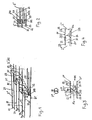
- Fig. 1 a simplified representation of two telescoped pieces of board, alternately coming from one of the two guide tracks for the same
- the Fig. 2 shows a plan view of the pushed together pieces of board from each different tracks
- the Fig. 3 a side view of an interface of two pieces of board from the different tracks, which have a groove on the top and bottom
- the Fig. 4 two board pieces, in which an approximately quarter-circle-like overlap of the groove ends in the longitudinal direction projecting web ends is provided
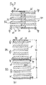
- Fig. 5a to 5c in each case side views of the end areas, two coming from the different tracks pieces of board with elimination of a faulty pieces of board with various forms of overlapping the web ends for only top side grooved pieces of board
- the Fig. 5a to 5c in each case side views of the end areas, two coming from the different tracks pieces of board with elimination of a faulty pieces of board with various forms of overlapping the web ends for only top side grooved pieces of board
- the Fig. 5a to 5c in each case side views
- FIG. 6a to 6c also in side views different forms of overlapping the web ends of pieces of board with top and bottom Grooving, the Fig. 7a and 7b each in plan view, each along their side edges differently grooved pieces of board, which are ultimately to be joined together side by side and finally the Fig. 8 a new plant for the production of endless boards grooved only on one side and of grooved single boards of any desired length.
- the oblique view of the Fig. 1 shows how at the front end of a piece of board 2 "from the conveyor B2 at an angle ⁇ or (180- ⁇ ) to the top 21 of the same obliquely projecting ends 203 of this only three webs 23 having board piece 2" in - the grooves 22nd corresponding gaps between the on the other side or rearwardly projecting web ends 203 of moving in the web 1 board piece 2 'are pushed.
- the obliquely "overhanging" web ends 203 have been formed by oblique cuts S1 at the rear end of the board piece 2 'and by an oblique cut S2 at the front end of the board piece 2 "from the second web B2
- the underside of the approximately comb-like cross sections with base beams and teeth Board pieces 2 ', 2 " is designated by 21'.
- the Fig. 2 shows - with otherwise constant reference numerals - the nesting of the web ends 203 of two consecutive board pieces 2 ', 2 "clearly, where the webs 23 are highlighted with hatching.
- the Fig. 3 shows - with otherwise constant reference numerals - an "interface" between two pieces of board 2 'and 2 ", which have grooves 22 and webs 23 on top and bottom, the waste board piece 2"' with the inhomogeneity 29 already removed from the locomotion B1 is.
- the groove bases approximately in the median plane Me are each to the board top 21 and the board bottom 21 'with angle ⁇ oblique groove ends 203 in front, which in each case on both sides - as in Fig. 1 and 2 sketched - again "bridge-end in bridge gap” pushed together and are thus bound together.
- the angled sections S1 and S2 here are each realized with partial sections S1 ', S1 ", and S2', S2".
- the Fig. 4 shows - with otherwise constant reference numerals - also an "interface" between two board pieces 2 ', 2 "with only top grooving, in which case the projecting web-ends 203 are not running obliquely overlapping each other, but approximately quarter-circle with quarter circle Bk.
- Fig. 5a to 5c show - with otherwise constant reference numerals - schematically each in side view, the different ways of guiding the cuts S1, S2 when cutting inhomogeneity sites 29 having waste pieces 2 '"from the board 2 in the lane 1 and the insertion of a piece of board obtained in the same way.
- the Fig. 5a to 5c furthermore show the board pieces 2 ', 2 "and 2' which are ultimately pushed together to form an endless board 20.
- the Fig. 5a shows the cutting of a waste board piece 2 '"by two mutually symmetrical" overhanging "bevels S1, S2 each at an angle ⁇ to the board top 21 and inserting a similar shaped board piece 2" from the web 2 between the two board pieces 2' of the web 1 and the Telescoping the three board pieces 2 ', 2 ", 2'.
- Fig. 5b as each having a section S1 vertical to the top of the board piece 2 'and an "overhanging" oblique section 2 an asymmetrical side view having waste board piece 2'"is cut out of a board 20 and as from the second track B2 in the gap between the board pieces 2 'and 2 "an equally cut piece of board 2" is inserted and how then the telescoping successive board pieces 2', 2 ", 2 'to the endless board 20 takes place.
- the Fig. 5c shows how from the boards 3 in the second track B2 in each case elongated rectangular board pieces 2 "are cut out and each similarly shaped board pieces 2" are further promoted and from the boards 2 in the first track B1 in each case approximately trapezoidal Abfallbrett Genevae 2 '" be cut out and here in side view inverted trapezoidal shape having board pieces 2 'remain, which are pushed apart again in the conveying direction Lr and in the vacant gap Ab between them the rectangular in side view board piece 2 "is inserted from the web B2 and finally the board pieces 2' , 2 ", 2 'are pushed together again.
- Fig. 6a to 6c show - with otherwise constant reference numerals - also in side view, the union of board pieces 2 ', 2 "with grooves 22 and webs 23 both on the top 21 and on the bottom 21' of the board pieces 2 'and 2".
- Fig. 6b shows how in the first path B1 to the top 21 at an acute angle ⁇ overhanging oblique cuts in the pieces of board 2 'are cut to the median plane Me and then kinkend each a partial section at right angles to the bottom 21' is arranged.
- the boards 2 on the second web B2 is arranged from the top 21 to the same perpendicular (90 °) directed partial section, which is continued from the median plane Me to the bottom 21 'out each as an oblique partial section.
- a piece of board 2 is inserted from the second track B2 and then pushing them together in the order 2', 2", 2 'to the endless board 20 takes place.
- the Fig. 6c shows how each in the first path B1 swept to each other, each open angle-generating partial cuts so top and bottom projecting, angle ⁇ inclined web ends 203 are cut into the board pieces 2 'and in the second track B2 each board pieces 2' with vertical to Top 21 and the underside 21 'aligned cuts are introduced and the board pieces 2 ", introduced into the gap between the board pieces 2 and ultimately in the order 2', 2", 2 'pushed together and ultimately glued to the endless board 20.
- the Fig. 7a and 7b explain the embodiment of the board pieces 2 ', 2 "with each at the side edges only half a width bn / 2 and bs / 2 having grooves 22 and webs 23, wherein the Fig. 7a concerns the embodiment in which the board pieces 2 'in the first path B1 are each designed with a half-wide bn / 2 open groove on both sides while the board pieces 2 "of the second web B2 with lateral, each half the web width bs / 2 having webs 23 are executed.
- board pieces 2 ', 2 "with grooves 22 and webs 23 are produced in both locomotion paths B1, B2, wherein an open groove 22 with half the groove width bn / 2 is arranged along each of the two side edges and along the respective other side edge Bridge 23 is arranged with half web width bs / 2.
- the board pieces 2 'and 2 "of each of the webs B1, B2 then pass longitudinally past at least one sensor 93 connected to the control device 9 via a transverse conveyor 13 into the grooving saw 6, where the board pieces 2', 2" are cut by means of milling heads 60 in each of the tracks B1, B2 are incorporated here from the top of each of the grooves.
- grooved boards can then be tailored as needed to vertical or inclined cavity moldings and are joined together after rotation by 90 ° laterally to flat plates, which form the basic products for the above-mentioned light wood products.
Landscapes
- Life Sciences & Earth Sciences (AREA)
- Engineering & Computer Science (AREA)
- Wood Science & Technology (AREA)
- Mechanical Engineering (AREA)
- Forests & Forestry (AREA)
- Dry Formation Of Fiberboard And The Like (AREA)
Applications Claiming Priority (1)
| Application Number | Priority Date | Filing Date | Title |
|---|---|---|---|
| AT9592007A AT505486B1 (de) | 2007-06-20 | 2007-06-20 | Verfahren zur herstellung von mit nuten versehenen endlosbrettern und anlage zur durchfuhrung des verfahrens |
Publications (1)
| Publication Number | Publication Date |
|---|---|
| EP2006060A1 true EP2006060A1 (fr) | 2008-12-24 |
Family
ID=39735093
Family Applications (1)
| Application Number | Title | Priority Date | Filing Date |
|---|---|---|---|
| EP08450091A Withdrawn EP2006060A1 (fr) | 2007-06-20 | 2008-06-19 | Procédé de fabrication de planches sans fin pourvues de rainures et installation destinée à l'exécution du procédé |
Country Status (2)
| Country | Link |
|---|---|
| EP (1) | EP2006060A1 (fr) |
| AT (1) | AT505486B1 (fr) |
Cited By (1)
| Publication number | Priority date | Publication date | Assignee | Title |
|---|---|---|---|---|
| EP2522475A1 (fr) | 2009-04-30 | 2012-11-14 | Fill Gesellschaft m.b.H. | Dispositif pour détecter et corriger des points défectueux dans le bois |
Families Citing this family (1)
| Publication number | Priority date | Publication date | Assignee | Title |
|---|---|---|---|---|
| CH709486A2 (de) * | 2014-04-11 | 2015-10-15 | Bionicalpha Ag | Leichtbauelement, Herstellungsverfahren dafür, Verwendung desselben, sowie Leichtbauplatte und Dämmstoff. |
Citations (6)
| Publication number | Priority date | Publication date | Assignee | Title |
|---|---|---|---|---|
| US4054165A (en) | 1974-03-14 | 1977-10-18 | Karakawa Fancy Plywood Works Ltd. | Grooved sheet material |
| EP1288386A1 (fr) | 2001-09-04 | 2003-03-05 | Vorarlberger Ökohaus GmbH | Elément de paroi ou plafond |
| DE10260970A1 (de) | 2002-12-24 | 2004-07-15 | Nkt-Neue-Keilzink-Technologie Maschinenbau Gmbh | Keilzinkanlage |
| US20040199283A1 (en) * | 2002-08-20 | 2004-10-07 | Dick Spencer B. | Salvage methods and apparatus |
| WO2006081596A1 (fr) | 2005-02-04 | 2006-08-10 | Johann Berger | Panneau de construction, element de construction ou similaire |
| WO2007048149A1 (fr) | 2005-10-28 | 2007-05-03 | Johann Berger | Plaque de construction ou similaire, procédé de fabrication et utilisation |
-
2007
- 2007-06-20 AT AT9592007A patent/AT505486B1/de not_active IP Right Cessation
-
2008
- 2008-06-19 EP EP08450091A patent/EP2006060A1/fr not_active Withdrawn
Patent Citations (6)
| Publication number | Priority date | Publication date | Assignee | Title |
|---|---|---|---|---|
| US4054165A (en) | 1974-03-14 | 1977-10-18 | Karakawa Fancy Plywood Works Ltd. | Grooved sheet material |
| EP1288386A1 (fr) | 2001-09-04 | 2003-03-05 | Vorarlberger Ökohaus GmbH | Elément de paroi ou plafond |
| US20040199283A1 (en) * | 2002-08-20 | 2004-10-07 | Dick Spencer B. | Salvage methods and apparatus |
| DE10260970A1 (de) | 2002-12-24 | 2004-07-15 | Nkt-Neue-Keilzink-Technologie Maschinenbau Gmbh | Keilzinkanlage |
| WO2006081596A1 (fr) | 2005-02-04 | 2006-08-10 | Johann Berger | Panneau de construction, element de construction ou similaire |
| WO2007048149A1 (fr) | 2005-10-28 | 2007-05-03 | Johann Berger | Plaque de construction ou similaire, procédé de fabrication et utilisation |
Cited By (2)
| Publication number | Priority date | Publication date | Assignee | Title |
|---|---|---|---|---|
| EP2522475A1 (fr) | 2009-04-30 | 2012-11-14 | Fill Gesellschaft m.b.H. | Dispositif pour détecter et corriger des points défectueux dans le bois |
| DE202010017997U1 (de) | 2009-04-30 | 2013-07-08 | Fill Gesellschaft M.B.H. | Vorrichtung zum Erkennen und Korrigieren von Fehlstellen in Holz |
Also Published As
| Publication number | Publication date |
|---|---|
| AT505486B1 (de) | 2009-04-15 |
| AT505486A1 (de) | 2009-01-15 |
Similar Documents
| Publication | Publication Date | Title |
|---|---|---|
| EP1674223B1 (fr) | Dispositif d'insertion d'éléments de liaison dans les faces frontales et/ou latérales de produits techniques en bois | |
| DE3343954A1 (de) | Verfahren zum aufteilen gekruemmter holzstuecke und vorrichtung zur ausfuehrung des verfahrens | |
| DE102009022335A1 (de) | Verfahren zur Herstellung von Holzplatten | |
| AT505486B1 (de) | Verfahren zur herstellung von mit nuten versehenen endlosbrettern und anlage zur durchfuhrung des verfahrens | |
| EP3045278B1 (fr) | Procede de fabrication de planches et/ou de blocs en bois | |
| AT505855B1 (de) | Verfahren zur herstellung von endlos-brettern | |
| AT507231B1 (de) | Verfahren und vorrichtung zur herstellung von kreuzlagen-platten | |
| DE2920755A1 (de) | Einrichtung und verfahren zum stirnseitigen zusammensetzen von hoelzern mittels keilzinkenverbindungen | |
| DE10344161B4 (de) | Verfahren zum Herstellen einer aus Faserplatten bestehenden Rückwand für Möbel | |
| DE102008061766B4 (de) | Verfahren zur Herstellung von durch Keilzinkenverbindung zusammengesetzten Werkstücken bestehenden Bauelementen und Vorrichtung zur Durchführung dieses Verfahrens | |
| DE102023116006B3 (de) | Verfahren zum Herstellen von mit Ausschnitten versehenen Brettsperrholzplatten | |
| DE102011054165B4 (de) | Verfahren zur Herstellung von Keilbohlen | |
| EP3042744A1 (fr) | Lamelles en bois naturel et planches, plaques et poutres etant ainsi fabriquees | |
| DE202022100647U1 (de) | Keilzinkanlage und Verbindungsstation für Keilzinkanlage | |
| DE3913160A1 (de) | Verfahren zum herstellen einer fertigplatte aus holz oder holzmaterial sowie eine nach diesem verfahren hergestellte fertigplatte | |
| DE2347073C3 (de) | Verfahren zur Herstellung von Mittellagen für Tischlerplatten | |
| EP2740575A1 (fr) | Dispositif et procédé destinés au traitement de plaques | |
| AT516697A1 (de) | Lamellen aus Naturholz, damit gefertigte Bretter, Balken und Platten | |
| DE3820148C2 (fr) | ||
| DE3318743C2 (fr) | ||
| AT285147B (de) | Verfahren zur Herstellung großflächiger Holzplatten | |
| DE10100583A1 (de) | Fußbodenelement und Verfahren zu dessen Herstellung | |
| DE2235341A1 (de) | Verfahren zur herstellung von bauteilen fuer parkettsperrholzbretter und vorrichtung zur herstellung derartiger bauteile | |
| WO2003097963A1 (fr) | Element de revetement de sol et son procede de production | |
| DE102008061765A1 (de) | Verfahren zur Herstellung von durch Keilzinkenverbindungen zusammengesetzten Werkstücken gebildeten Bauelementen und Vorrichtung zur Durchführung dieses Verfahrens |
Legal Events
| Date | Code | Title | Description |
|---|---|---|---|
| PUAI | Public reference made under article 153(3) epc to a published international application that has entered the european phase |
Free format text: ORIGINAL CODE: 0009012 |
|
| AK | Designated contracting states |
Kind code of ref document: A1 Designated state(s): AT BE BG CH CY CZ DE DK EE ES FI FR GB GR HR HU IE IS IT LI LT LU LV MC MT NL NO PL PT RO SE SI SK TR |
|
| AX | Request for extension of the european patent |
Extension state: AL BA MK RS |
|
| AKX | Designation fees paid | ||
| REG | Reference to a national code |
Ref country code: DE Ref legal event code: 8566 |
|
| STAA | Information on the status of an ep patent application or granted ep patent |
Free format text: STATUS: THE APPLICATION IS DEEMED TO BE WITHDRAWN |
|
| 18D | Application deemed to be withdrawn |
Effective date: 20090625 |