EP2006060A1 - Method for producing endless planks with grooves and apparatus for carrying out the method - Google Patents
Method for producing endless planks with grooves and apparatus for carrying out the method Download PDFInfo
- Publication number
- EP2006060A1 EP2006060A1 EP08450091A EP08450091A EP2006060A1 EP 2006060 A1 EP2006060 A1 EP 2006060A1 EP 08450091 A EP08450091 A EP 08450091A EP 08450091 A EP08450091 A EP 08450091A EP 2006060 A1 EP2006060 A1 EP 2006060A1
- Authority
- EP
- European Patent Office
- Prior art keywords
- board
- boards
- pieces
- inhomogeneity
- tracks
- Prior art date
- Legal status (The legal status is an assumption and is not a legal conclusion. Google has not performed a legal analysis and makes no representation as to the accuracy of the status listed.)
- Withdrawn
Links
Images


Classifications
-
- B—PERFORMING OPERATIONS; TRANSPORTING
- B27—WORKING OR PRESERVING WOOD OR SIMILAR MATERIAL; NAILING OR STAPLING MACHINES IN GENERAL
- B27F—DOVETAILED WORK; TENONS; SLOTTING MACHINES FOR WOOD OR SIMILAR MATERIAL; NAILING OR STAPLING MACHINES
- B27F1/00—Dovetailed work; Tenons; Making tongues or grooves; Groove- and- tongue jointed work; Finger- joints
- B27F1/02—Making tongues or grooves, of indefinite length
-
- B—PERFORMING OPERATIONS; TRANSPORTING
- B27—WORKING OR PRESERVING WOOD OR SIMILAR MATERIAL; NAILING OR STAPLING MACHINES IN GENERAL
- B27F—DOVETAILED WORK; TENONS; SLOTTING MACHINES FOR WOOD OR SIMILAR MATERIAL; NAILING OR STAPLING MACHINES
- B27F1/00—Dovetailed work; Tenons; Making tongues or grooves; Groove- and- tongue jointed work; Finger- joints
- B27F1/16—Making finger joints, i.e. joints having tapers in the opposite direction to those of dovetail joints
-
- B—PERFORMING OPERATIONS; TRANSPORTING
- B27—WORKING OR PRESERVING WOOD OR SIMILAR MATERIAL; NAILING OR STAPLING MACHINES IN GENERAL
- B27G—ACCESSORY MACHINES OR APPARATUS FOR WORKING WOOD OR SIMILAR MATERIALS; TOOLS FOR WORKING WOOD OR SIMILAR MATERIALS; SAFETY DEVICES FOR WOOD WORKING MACHINES OR TOOLS
- B27G1/00—Machines or devices for removing knots or other irregularities or for filling-up holes
Definitions
- the invention relates to a new method for the continuous production of at least on the top with a plurality of grooves and webs provided endless boards according to the preamble of claim 1 and a system for the effective implementation of the new method.
- Such grooved boards form tailored in each required length, for example, a starting product for the production of lightweight wood panels and in particular for the vertical cavity panels according to WO 2006/081596 A1 and for the inclined cavity plates according to WO 2007/048149 A1 ,
- the state of the art is as follows:
- the DE 102 609 70 A1 shows a finger jointing machine, which has at least one milling device, a buffer table and at least one downstream of this separating and transfer station for transfer to a pressing station and at least one arranged between the buffer table and transfer station movable distribution table.
- the EP 1 288 386 A1 discloses a wall or ceiling element which is formed of a plurality of layers of boards whose surfaces are provided with a plurality of recesses.
- the aim of the invention was to develop a process using the existing today technical conditions, which significantly simplifies the production of particular for the production of special light wood building boards for a variety of applications from furniture to equipment to large buildings and mechanically high-quality wood Products of various kinds leads.
- the new method for producing the grooved endless boards has the enumerated in the characterizing part of claim 1 essential features.
- the new process ensures the preservation of - of inhomogeneities in the wood fiber profile, the boards used as starting material, in particular od branches, flaws, voids. Like., Essentially freed, grooved endless boards or single boards.
- the same is provided for a movement-speed-dependent determination of the longitudinal extent of the inhomogeneity in the longitudinal direction of movement.
- the new method allows a particularly effective and trouble-free production of a high quality precursor, especially for the new cavity plates, according to the above published PCT applications but is also suitable for the production of other such products.
- the new method is suitable in modified analog form further for the production of such grooved endless boards, which have grooves on both sides, and then finally to so-called Doppelkamm advisorn for the production of the new cavity plates can be processed.
- This variant of the method is described in more detail in claim 2, wherein also inhomogeneities in the wood fiber profile of the boards used as starting material, in particular od branches, flaws, blowholes or the like, are removed as far as possible.
- the optical sensors are used for a movement-speed-dependent determination of the longitudinal extent of the inhomogeneities in the longitudinal direction of movement of the boards.
- one embodiment of the new method according to claim 3 for the production of both sides narrowed Grooves and / or webs of advantage.
- This procedure is used in particular to avoid thickened webs or widened grooves in a side-by-side abutting and bonding the grooved boards, for example, for a further production of vertical or inclined cavity plates.
- the invention is in no way limited to a projection of the web ends on the Nutenden at least on one side of the board pieces in the form of a triangle with obliquely downward hypotenuse, but that any other course of this "hypotenuse" is possible.
- the claim 5 is an approximately quarter-circle-like course from the top of the board piece or from the webs to the bottom of the same can be seen.
- Another essential subject of the invention is an effective system for performing the method according to the preamble of claim 6, which has the essential features appearing in the characterizing part of this claim.
- the charging device provided according to this claim is used in particular for the guidance of boards of similar width and thickness in at least two webs equipped with longitudinal locomotion drives.
- the cutting blades provided in accordance with this claim ensure that by executing each two, preferably substantially perpendicular, to the direction of movement of the boards, but each at an acute angle and / or perpendicular to the board top through the boards out of the boards Webs a substantially symmetrical or asymmetrical (with a rectangular side) trapezoidal longitudinal shape having, the determined inhomogeneity point exhibiting waste wood piece is removed from the respective web and accordingly two each with acute angles at the top or two each with a right and a acute angle to the top back and front cut pieces of board remain in the respective lane and continue to move there.
- the milling device is used for the incorporation, in particular milling of the grooves in the pieces of wood.
- the separation device provided in accordance with this claim is provided for the generation of gaps or longitudinal distances sufficient for the insertion of a board piece from the respective other track between two board pieces guided in succession along one of the two tracks.
- the claim 7 relates to an important according to the invention component of the new plant for the production of grooved endless boards, which is taken to ensure that between each board pieces on one of the two conveyor tracks a piece of board from the other web with its webs and grooves in those Sites where the board pieces of the first web just have grooves and webs, is inserted, so that a longitudinal telescoping of the board pieces from the first and from the second path is in each case alternately allows for the formation of the endless board.
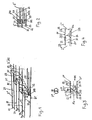
- Fig. 1 a simplified representation of two telescoped pieces of board, alternately coming from one of the two guide tracks for the same
- the Fig. 2 shows a plan view of the pushed together pieces of board from each different tracks
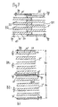
- the Fig. 3 a side view of an interface of two pieces of board from the different tracks, which have a groove on the top and bottom
- the Fig. 4 two board pieces, in which an approximately quarter-circle-like overlap of the groove ends in the longitudinal direction projecting web ends is provided
- Fig. 5a to 5c in each case side views of the end areas, two coming from the different tracks pieces of board with elimination of a faulty pieces of board with various forms of overlapping the web ends for only top side grooved pieces of board
- the Fig. 5a to 5c in each case side views of the end areas, two coming from the different tracks pieces of board with elimination of a faulty pieces of board with various forms of overlapping the web ends for only top side grooved pieces of board
- the Fig. 5a to 5c in each case side views
- FIG. 6a to 6c also in side views different forms of overlapping the web ends of pieces of board with top and bottom Grooving, the Fig. 7a and 7b each in plan view, each along their side edges differently grooved pieces of board, which are ultimately to be joined together side by side and finally the Fig. 8 a new plant for the production of endless boards grooved only on one side and of grooved single boards of any desired length.
- the oblique view of the Fig. 1 shows how at the front end of a piece of board 2 "from the conveyor B2 at an angle ⁇ or (180- ⁇ ) to the top 21 of the same obliquely projecting ends 203 of this only three webs 23 having board piece 2" in - the grooves 22nd corresponding gaps between the on the other side or rearwardly projecting web ends 203 of moving in the web 1 board piece 2 'are pushed.
- the obliquely "overhanging" web ends 203 have been formed by oblique cuts S1 at the rear end of the board piece 2 'and by an oblique cut S2 at the front end of the board piece 2 "from the second web B2
- the underside of the approximately comb-like cross sections with base beams and teeth Board pieces 2 ', 2 " is designated by 21'.
- the Fig. 2 shows - with otherwise constant reference numerals - the nesting of the web ends 203 of two consecutive board pieces 2 ', 2 "clearly, where the webs 23 are highlighted with hatching.
- the Fig. 3 shows - with otherwise constant reference numerals - an "interface" between two pieces of board 2 'and 2 ", which have grooves 22 and webs 23 on top and bottom, the waste board piece 2"' with the inhomogeneity 29 already removed from the locomotion B1 is.
- the groove bases approximately in the median plane Me are each to the board top 21 and the board bottom 21 'with angle ⁇ oblique groove ends 203 in front, which in each case on both sides - as in Fig. 1 and 2 sketched - again "bridge-end in bridge gap” pushed together and are thus bound together.
- the angled sections S1 and S2 here are each realized with partial sections S1 ', S1 ", and S2', S2".
- the Fig. 4 shows - with otherwise constant reference numerals - also an "interface" between two board pieces 2 ', 2 "with only top grooving, in which case the projecting web-ends 203 are not running obliquely overlapping each other, but approximately quarter-circle with quarter circle Bk.
- Fig. 5a to 5c show - with otherwise constant reference numerals - schematically each in side view, the different ways of guiding the cuts S1, S2 when cutting inhomogeneity sites 29 having waste pieces 2 '"from the board 2 in the lane 1 and the insertion of a piece of board obtained in the same way.
- the Fig. 5a to 5c furthermore show the board pieces 2 ', 2 "and 2' which are ultimately pushed together to form an endless board 20.
- the Fig. 5a shows the cutting of a waste board piece 2 '"by two mutually symmetrical" overhanging "bevels S1, S2 each at an angle ⁇ to the board top 21 and inserting a similar shaped board piece 2" from the web 2 between the two board pieces 2' of the web 1 and the Telescoping the three board pieces 2 ', 2 ", 2'.
- Fig. 5b as each having a section S1 vertical to the top of the board piece 2 'and an "overhanging" oblique section 2 an asymmetrical side view having waste board piece 2'"is cut out of a board 20 and as from the second track B2 in the gap between the board pieces 2 'and 2 "an equally cut piece of board 2" is inserted and how then the telescoping successive board pieces 2', 2 ", 2 'to the endless board 20 takes place.
- the Fig. 5c shows how from the boards 3 in the second track B2 in each case elongated rectangular board pieces 2 "are cut out and each similarly shaped board pieces 2" are further promoted and from the boards 2 in the first track B1 in each case approximately trapezoidal Abfallbrett Genevae 2 '" be cut out and here in side view inverted trapezoidal shape having board pieces 2 'remain, which are pushed apart again in the conveying direction Lr and in the vacant gap Ab between them the rectangular in side view board piece 2 "is inserted from the web B2 and finally the board pieces 2' , 2 ", 2 'are pushed together again.
- Fig. 6a to 6c show - with otherwise constant reference numerals - also in side view, the union of board pieces 2 ', 2 "with grooves 22 and webs 23 both on the top 21 and on the bottom 21' of the board pieces 2 'and 2".
- Fig. 6b shows how in the first path B1 to the top 21 at an acute angle ⁇ overhanging oblique cuts in the pieces of board 2 'are cut to the median plane Me and then kinkend each a partial section at right angles to the bottom 21' is arranged.
- the boards 2 on the second web B2 is arranged from the top 21 to the same perpendicular (90 °) directed partial section, which is continued from the median plane Me to the bottom 21 'out each as an oblique partial section.
- a piece of board 2 is inserted from the second track B2 and then pushing them together in the order 2', 2", 2 'to the endless board 20 takes place.
- the Fig. 6c shows how each in the first path B1 swept to each other, each open angle-generating partial cuts so top and bottom projecting, angle ⁇ inclined web ends 203 are cut into the board pieces 2 'and in the second track B2 each board pieces 2' with vertical to Top 21 and the underside 21 'aligned cuts are introduced and the board pieces 2 ", introduced into the gap between the board pieces 2 and ultimately in the order 2', 2", 2 'pushed together and ultimately glued to the endless board 20.
- the Fig. 7a and 7b explain the embodiment of the board pieces 2 ', 2 "with each at the side edges only half a width bn / 2 and bs / 2 having grooves 22 and webs 23, wherein the Fig. 7a concerns the embodiment in which the board pieces 2 'in the first path B1 are each designed with a half-wide bn / 2 open groove on both sides while the board pieces 2 "of the second web B2 with lateral, each half the web width bs / 2 having webs 23 are executed.
- board pieces 2 ', 2 "with grooves 22 and webs 23 are produced in both locomotion paths B1, B2, wherein an open groove 22 with half the groove width bn / 2 is arranged along each of the two side edges and along the respective other side edge Bridge 23 is arranged with half web width bs / 2.
- the board pieces 2 'and 2 "of each of the webs B1, B2 then pass longitudinally past at least one sensor 93 connected to the control device 9 via a transverse conveyor 13 into the grooving saw 6, where the board pieces 2', 2" are cut by means of milling heads 60 in each of the tracks B1, B2 are incorporated here from the top of each of the grooves.
- grooved boards can then be tailored as needed to vertical or inclined cavity moldings and are joined together after rotation by 90 ° laterally to flat plates, which form the basic products for the above-mentioned light wood products.
Landscapes
- Life Sciences & Earth Sciences (AREA)
- Engineering & Computer Science (AREA)
- Wood Science & Technology (AREA)
- Mechanical Engineering (AREA)
- Forests & Forestry (AREA)
- Dry Formation Of Fiberboard And The Like (AREA)
Abstract
Description
Die Erfindung betrifft ein neues Verfahren zur kontinuierlichen Herstellung von zumindest auf der Oberseite mit einer Mehrzahl von Nuten und Stegen versehenen Endlosbrettern gemäß dem Oberbegriff des Anspruches 1 sowie eine Anlage zur effektiven Durchführung des neuen Verfahrens.The invention relates to a new method for the continuous production of at least on the top with a plurality of grooves and webs provided endless boards according to the preamble of
Derartig genutete Bretter bilden in jeweils benötigter Länge zugeschnitten, beispielsweise ein Ausgangsprodukt für die Herstellung von Leicht-Holzplatten und im besonderen für die Vertikal-Hohlraumplatten gemäß
Zum Stand der Technik ist folgendes auszuführen: Die
Aus der
Die
Diese Druckschriften beschreiben Verfahren und Vorrichtungen zur Holzbearbeitung, die mehrere parallel und/oder seriell ablaufende Arbeitsschritte umfassen. Sie beschreiben jedoch kein Verfahren und keine Vorrichtung zur Herstellung von an der Oberfläche mit mehreren Nuten versehenen Endlos-Brettern, welche schließlich zu genuteten Brettern gewünschter Länge abgelängt werden und legt ein solches bzw. eine solche auch nicht nahe.These documents describe methods and apparatus for woodworking, which include several parallel and / or serial operations. However, they do not disclose or suggest a method and apparatus for making multi-notched surface continuous boards which are eventually cut to grooved boards of desired length.
Ziel der Erfindung war es, unter Nutzung der heute gegebenen technischen Voraussetzungen ein Verfahren zu entwickeln, welches die Herstellung der insbesondere für die Produktion der speziellen Leichtholz-Bauplatten für verschiedenste Anwendungszwecke vom Möbelbau über den Ausstattungsbau bis zu Großbauten hin wesentlich vereinfacht und zu mechanisch hochwertigen Holz-Produkten der verschiedensten Art führt.The aim of the invention was to develop a process using the existing today technical conditions, which significantly simplifies the production of particular for the production of special light wood building boards for a variety of applications from furniture to equipment to large buildings and mechanically high-quality wood Products of various kinds leads.
Das neue Verfahren zur Herstellung der genuteten Endlos-Bretter weist die im kennzeichnenden Teil des Anspruches 1 aufgezählten wesentlichen Merkmale auf.The new method for producing the grooved endless boards has the enumerated in the characterizing part of
Das neue Verfahren sichert den Erhalt von - von Inhomogenitäten im Holz-Faserverlauf, der als Ausgangsmaterial eingesetzten Bretter, wie insbesondere Astabzweigungen, Fehlstellen, Lunkern od. dgl., im wesentlichen befreiten, genuteten Endlos-Brettern bzw. Einzelbrettern.The new process ensures the preservation of - of inhomogeneities in the wood fiber profile, the boards used as starting material, in particular od branches, flaws, voids. Like., Essentially freed, grooved endless boards or single boards.
Was den gemäß dem Anspruch 1 vorgesehenen optischen Sensor betrifft, so ist derselbe für eine bewegungsgeschwindigkeits-abhängige Ermittlung der Längsausdehnung der Inhomogenität in Längs-Bewegungsrichtung vorgesehen.As regards the optical sensor provided according to
Das neue Verfahren ermöglicht eine besonders effektive und störungsfreie Produktion eines hochqualitativen Vorproduktes, insbesondere für die neuen Hohlraumplatten, gemäß den oben genannten veröffentlichten PCT-Anmeldungen ist aber auch für die Herstellung von anderen derartigen Produkten geeignet.The new method allows a particularly effective and trouble-free production of a high quality precursor, especially for the new cavity plates, according to the above published PCT applications but is also suitable for the production of other such products.
Bei dem neuen Verfahren werden Bretter erhalten, bei welchen jeweils in Länge der einzelnen sie bildenden Brettstücke Nuten und Stege einander abwechseln bzw. umgekehrt.In the new method boards are obtained, in which in each case in length of the individual board pieces forming grooves and webs alternate with each other or vice versa.
Das neue Verfahren eignet sich in abgewandelter analoger Form weiters zur Herstellung von derartig genuteten Endlosbrettern, welche beidseitig Nuten aufweisen, und dann schließlich zu sogenannten Doppelkammleisten für die Herstellung der neuen Hohlraumplatten verarbeitet werden können. Diese Verfahrensvariante ist im Anspruch 2 näher beschrieben, wobei auch hier Inhomogenitäten im Holz-Faserverlauf der als Ausgangsmaterial eingesetzten Bretter wie insbesondere Astabzweigungen, Fehlstellen, Lunker od. dgl. weitest gehend entfernt werden. Auch hier dienen die optischen Sensoren für eine bewegungsgeschwindigkeits-abhängige Ermittlung der Längsausdehnung der Inhomogenitäten in Längs-Bewegungsrichtung der Bretter.The new method is suitable in modified analog form further for the production of such grooved endless boards, which have grooves on both sides, and then finally to so-called Doppelkammleisten for the production of the new cavity plates can be processed. This variant of the method is described in more detail in
Um bei einem seitlichen Nebeneinanderlegen und Aneinanderbinden bzw. -leimen der neuen genuteten Endlos-Bretter "verbreiterte" Nuten und/oder "verdickte" Stege an den seitlichen Verbindungsstellen zu vermeiden, ist eine Ausführungsart des neuen Verfahrens gemäß Anspruch 3 zur Herstellung von jeweils beidseitig verschmälerten Nuten und/oder Stegen von Vorteil.In order to avoid "widening" grooves and / or "thickened" webs at the lateral connection points in the lateral juxtaposition and bonding of the new grooved endless boards, one embodiment of the new method according to claim 3 for the production of both sides narrowed Grooves and / or webs of advantage.
Diese Vorgangsweise dient insbesondere zur Vermeidung von verdickten Stegen oder verbreiterten Nuten bei einem Seit-an-Seit-Aneinanderliegen und Aneinanderbinden der genuteten Bretter, beispielsweise für eine weiterführende Produktion von Vertikal- oder Schräg-Hohlraumplatten.This procedure is used in particular to avoid thickened webs or widened grooves in a side-by-side abutting and bonding the grooved boards, for example, for a further production of vertical or inclined cavity plates.
Um die exakte Führung der Bretter, der nach Eliminierung der Brettstücke mit Inhomogenitätsstellen von denselben befreiten, verbleibenden und genuteten Brettstücke, des letztlich daraus gefertigten genuteten Endlosbretts und der aus demselben abgelängten genuteten Bretter in den beiden Förder- bzw. Fortbewegungsbahnen zu gewährleisten, ist eine Führungs- und Anschlagschiene zumindest auf einer Seite jeder der beiden Bahnen günstig, wie aus dem Anspruch 4 hervorgeht.In order to ensure the exact guidance of the boards, which after eliminating the board pieces with Inhomogenitätsstellen of the same, remaining and grooved pieces of board, ultimately produced therefrom grooved endless board and the same cut-grooved boards in the two conveyor or locomotion paths, is a guide - And stop rail at least on one side of each of the two tracks low, as is apparent from the claim 4.
Es soll an dieser Stelle betont werden, dass die Erfindung keineswegs auf ein Vorstehen der Stegenden über die Nutenden zumindest auf einer Seite der Brettstücke etwa in Form eines Dreieckes mit schräg nach unten gerichteter Hypotenuse beschränkt ist, sondern dass auch jeder andere Verlauf dieser "Hypotenuse" möglich ist. So ist dem Anspruch 5 ist ein etwa viertelkreis-artiger Verlauf von der Oberseite des Brettstücks bzw. von dessen Stegen zur Unterseite desselben zu entnehmen.It should be emphasized at this point that the invention is in no way limited to a projection of the web ends on the Nutenden at least on one side of the board pieces in the form of a triangle with obliquely downward hypotenuse, but that any other course of this "hypotenuse" is possible. Thus, the claim 5 is an approximately quarter-circle-like course from the top of the board piece or from the webs to the bottom of the same can be seen.
Ein weiterer wesentlicher Gegenstand der Erfindung ist eine effektiv arbeitende Anlage für die Durchführung des Verfahrens gemäß dem Oberbegrifff des Anspruches 6, welches die im kennzeichnenden Teil dieses Anspruches aufscheinenden wesentlichen Merkmale aufweist. Die gemäß diesem Anspruch vorgesehene Beschickungseinrichtung dient insbesondere für die Führung von in ihrer Breite und Dicke gleichartigen Bretter in zumindest zwei mit Längs-Fortbewegungsantrieben ausgestatteten, Bahnen.Another essential subject of the invention is an effective system for performing the method according to the preamble of claim 6, which has the essential features appearing in the characterizing part of this claim. The charging device provided according to this claim is used in particular for the guidance of boards of similar width and thickness in at least two webs equipped with longitudinal locomotion drives.
Die gemäß diesem Anspruch vorgesehenen Schneidmesser sorgen dafür, dass unter Ausführung von jeweils zwei, bevorzugt im wesentlichen senkrecht, zur Bewegungsrichtung der Bretter, jedoch jeweils in einem spitzen Winkel und/oder senkrecht zur Brett-Oberseite durch die Bretter geführten Schnitten aus den Brettern jeder der Bahnen ein im wesentlichen symmetrische oder unsymmetrische (mit einer Rechteckseite) Trapez-Längsschnitt-Form aufweisendes, die festgestellte Inhomogenitätsstelle aufweisendes Abfall-Holzstück aus der jeweiligen Bahn entfernt wird und dementsprechend jeweils zwei mit spitzen Winkeln an der Oberseite oder zwei mit je einem rechten und einem spitzen Winkel zur Oberseite rückseitig und vorderseitig zugeschnittene Brettstücke in der jeweiligen Bahn verbleiben und dort weiter fortbewegt werden.The cutting blades provided in accordance with this claim ensure that by executing each two, preferably substantially perpendicular, to the direction of movement of the boards, but each at an acute angle and / or perpendicular to the board top through the boards out of the boards Webs a substantially symmetrical or asymmetrical (with a rectangular side) trapezoidal longitudinal shape having, the determined inhomogeneity point exhibiting waste wood piece is removed from the respective web and accordingly two each with acute angles at the top or two each with a right and a acute angle to the top back and front cut pieces of board remain in the respective lane and continue to move there.
Die Fräseinrichtung dient für die Einarbeitung, insbesondere Einfräsung der Nuten in die Holzstücke .The milling device is used for the incorporation, in particular milling of the grooves in the pieces of wood.
Schließlich ist die gemäß diesem Anspruch vorgesehene Vereinzelungsvorrichtung für die Generierung von für den Einschub eines Brettstücks aus der jeweils anderen Bahn ausreichenden Lücken bzw. Längsabstände zwischen zwei hintereinander entlang einer der beiden Bahnen geführten Brettstücke vorgesehen.Finally, the separation device provided in accordance with this claim is provided for the generation of gaps or longitudinal distances sufficient for the insertion of a board piece from the respective other track between two board pieces guided in succession along one of the two tracks.
Der Anspruch 7 betrifft eine gemäß der Erfindung wichtige Komponente der neuen Anlage zur Herstellung von genuteten Endlos-Brettern, durch welche dafür gesorgt ist, dass jeweils zwischen zwei Brettstücken auf einer der beiden Förderbahnen ein Brettstück von der anderen Bahn mit seinen Stegen und Nuten an jenen Stellen, wo die Brettstücke der ersten Bahn gerade Nuten und Stege aufweisen, eingeschoben wird, so dass ein Längs-Ineinanderschieben der Brettstücke aus der ersten und aus der zweiten Bahn jeweils abwechselnd zur Bildung des Endlos-Brettes ermöglicht ist.The
Anhand der Zeichnung wird die Erfindung näher erläutert:Reference to the drawing, the invention is explained in more detail:
Es zeigen die
Die Schrägansicht der
Es ist anzumerken, dass an der Nahtstelle zwischen den beiden aufeinanderfolgenden Brettstücken 2', 2" etwa Dreiecksquerschnitt aufweisende, quasi Vollholzdichte Vhd aufweisende, kurze Stücke in dem aus den jeweils aufeinander folgenden Brettstücken 2', 2" gebildeten Endlosbrett 20 vorhanden sind. Weiters ist aus der
Die
Die
Die
Die
Die
Die
In analoger Weise zeigt die
Die
Die
Aus der
Die
Die
Beim seitlichen Aneinanderreihen der Brettstücke 2', 2" bzw. der aus denselben gebildeten Endlosbretter sind auf diese Weise Seit an Seit doppelte Breite 2bs aufweisende Stege 23 und doppelte Breite 2bn aufweisende Nuten 22 vermieden und an deren Stelle sind jeweils halbe Stegbreite bs/2 und insgesamt eine gesamte Stegbreite bs aufweisende Stege 23 bzw. eine Gesamtbreite bn aufweisende Nut oder aber jeweils aus einem halbbreiten Steg und einer halbbreiten Nut gebildete Nut-Stege angeordnet.In the lateral juxtaposition of the pieces of
Aus der
Dort werden in beiden Fortbewegungs-Bahnen B1, B2 Brettstücke 2', 2" mit Nuten 22 und Stegen 23 erzeugt, wobei jeweils entlang eines der beiden Seitenränder eine offene Nut 22 mit halber Nutbreite bn/2 angeordnet ist und entlang des jeweils anderen Seitenrandes ein Steg 23 mit halber Stegbreite bs/2 angeordnet ist.There,
Beim seitlichen aneinanderliegenden Verleimen der mit den miteinander verleimten Brettern 2', 2" hergestellten Endlosbretter 20 bzw. daraus abgelängten Bretter 200 zur Herstellung von Hohlraumleisten für Holz-Leichtplatten ist ebenso eine unerwünschte "Verdickung" von seitlich aneinander grenzenden Stegen 23 bzw. eine "Verbreiterung" der aneinandergrenzenden Nuten 22 von zwei seitlich aneinanderliegenden und miteinander verleimten Brettern 20 vermieden.When the adjacent glued together with the glued
Schließlich zeigt die
Von einem Magazin 10 für die als Ausgangsmaterial eingesetzten Bretter 2 mit Inhomogenitätsstellen 29 werden diese Bretter 2 mit Inhomogenitäten 29 in Längsbewegungsrichtung Lr zum Glätten von deren Oberflächen und zum Dimensionieren derselben auf gleiche Dicke und Breite bb durch eine Hobelmaschine 11 geführt und gelangen dann auf einen ersten Querförderer 12, wo sie zwei parallel zueinander geführten Fortbewegungsbahnen B1, B2 zugeführt werden. Die Bretter 2 laufen in jeder Bahn B1 und B2 unter einem optischen Sensor 91 durch, der mit der Steuerungseinheit 9 datenflussverbunden ist und diese steuert die Sägeblätter 31 für die Führung der Schnitte S1, S2 so dass jeweils in jeder Bahn B1, B2 ein Abfall-Brettstück 2'" mit Inhomogenität 29 in zumindest deren Länge a29 herausgeschnitten wird.From a
Danach gelangen die Brettstücke 2' und 2" jeder der Bahnen B1, B2, jeweils unter zumindest einen mit der Steuerungseinrichtung 9 datenflussverbundenen Sensor 93 längs vorbeigeführt, über einen Querförderer 13 in die Nutensäge 6, wo in die Brettstücke 2', 2" mittels Fräsköpfen 60 in jeder der Bahnen B1, B2 hier von der Oberseite jeweils die Nuten eingearbeitet werden.The
Die dann verschiedene Längen I1', I2'....In' bzw. I1", I2" In-1" aufweisenden Brettstücke 2', 2" gelangen dann in die Vereinzelungs-Einrichtung 70, wo die Abstände zwischen einander folgender Brettstücken 2' der ersten Bahn B1 auf die Länge In" des zwischen dieselben mittels der Einschiebe-Einrichtung 7 einzubringenden Brettstückes 2" eingestellt werden und die Transferierung der Brettstücke 2" aus der Bahn B2 in die Bahn B1 erfolgt.The then different lengths I1 ', I2' .... In 'or I1 ", I2" In-1 "having
Es erfolgt dann z.B. mit Hilfe von mit durch die Steuerungseinrichtung 9 gesteuerten, mit unterschiedlicher Geschwindigkeit laufenden Förderbändern ein Beleimen der Steg-Enden der Brettstücke 2', 2" mittels Beleimungsvorrichtung 85 und ein Längs-Ineinanderschieben derselben mittels Zusammenschiebungs-Einrichtung 80 sowie ein Pressen und/oder Erwärmen 81 der Leimstellen, wodurch aus den jeweils in der Reihenfolge 2', 2", 2', 2", 2' usw. aneinander gebundenen Brettstücken 2, 2' ein Endlos-Brett 20 gebildet wird, welches schließlich in der Abläng-Einrichtung 10 in Einzel-Bretter 200 mit jeweils gewünschter individueller Länge zugeschnitten wird.It then takes place e.g. by means of controlled by the
Diese genuteten Bretter können dann je nach Bedarf zu Vertikal- oder Schräg-Hohlraumleisten zugeschnitten werden und nach Verdrehung um 90° seitlich zu flächigen Platten zusammengefügt werden, welche die Grundprodukte für die eingangs erwähnten Leicht-Holzprodukte bilden.These grooved boards can then be tailored as needed to vertical or inclined cavity moldings and are joined together after rotation by 90 ° laterally to flat plates, which form the basic products for the above-mentioned light wood products.
Claims (7)
dadurch gekennzeichnet, dass
nach der Inhomogenitätsstelle (29) ein Schnitt (S2) in einem stumpfen Winkel (β) zur Brett-Oberseite (21), wobei es bevorzugt ist, wenn β = 180 - α,
oder
nach der Inhomogenitätsstelle (29) ein Schnitt (S2) in einem im wesentlichen rechten Winkel (90°) zur Brett-Oberseite (21),
oder
nach der Inhomogenitätsstelle (29) ein Schnitt (S2) in einem stumpfen Winkel (β) zur Brett-Oberseite (21), wobei es bevorzugt ist, wenn β = (180 - α)
oder aber, in einer der beiden Bahnen (B1, B2)
nach der Inhomogenitätsstelle (29) ein Schnitt (S2) in einem stumpfen Winkel (β) zur Brett-Oberseite (21), wobei es bevorzugt ist, wenn β = 180 - α,
und in der jeweils anderen Bahn (B2, B1)
vor der und nach der Inhomogenitätsstelle (29) ein Schnitt (S1) in einem im wesentlichen rechten Winkel (90°) zur Brett-Oberseite (21), und
characterized in that
after the inhomogeneity point (29) a section (S2) at an obtuse angle (β) to the board top (21), it being preferred if β = 180 - α,
or
after the inhomogeneity point (29) a section (S2) at a substantially right angle (90 °) to the board top (21),
or
after the inhomogeneity point (29) a section (S2) at an obtuse angle (β) to the board top (21), it being preferred if β = (180 - α)
or else, in one of the two lanes (B1, B2)
after the inhomogeneity point (29) a section (S2) at an obtuse angle (β) to the board top (21), it being preferred if β = 180 - α,
and in the other lane (B2, B1)
before and after the inhomogeneity point (29) a section (S1) at a substantially right angle (90 °) to the board top (21), and
dadurch gekennzeichnet,dass
oder
und - jeweils umgekehrt - nach oder vor der Inhomogenitätsstelle (29) mit einem insgesamt von der Brett-Ober(21)- und von der Brett-Unterseite (21') her ein im wesentlichen senkrechter (90°) Schnitt (S1, S2)
oder aber
und in der jeweils anderen Bahn (B2, B1) ein zur Brett-Oberseite (21) und zur Brett-Unterseite (21') im rechten Winkel verlaufenden Gesamtschnitt (S1, S2) geführt wird, und
dass weiters analog zu den Abschnitten III bis IX des Anspruches 1 verfahren wird. (Fig. 3, Fig. 6a - 6c)
characterized in that
or
and - reversed in each case - after or before the point of inhomogeneity (29) with a total of the board top (21) - and of the board bottom (21 ') ago a substantially vertical (90 °) cut (S1, S2)
or but
and in the respective other path (B2, B1) a to the board top (21) and the board bottom (21 ') at right angles extending overall section (S1, S2) is guided, and
that is further proceeding analogously to sections III to IX of claim 1. (Fig. 3, Fig. 6a - 6c)
dass entweder
that either
dadurch gekennzeichnet, dass die als Ausgangsmaterial eingesetzten Bretter (2), die aus ihnen gebildeten Brettstücke (2', 2") in ihren Bahnen (B1, B2) und das aus denselben nach deren Aneinanderreihung, Beleimung von deren über die Nut-Enden überstehenden Steg-Enden (203), und durch, gegebenenfalls erfolgendes, Seitverpressen und/oder Erwärmen gebildete Endlosbrett (20) zumindest bis zu dessen Ablängung in die einzelnen Bretter (200) entlang zumindest einer seitlichen Anschlags- und Führungsschiene der Bahnen (B1, B2) an dieselbe konstant anliegend fortbewegt werden.Method according to one of claims 1 to 3,
characterized in that the boards (2) used as starting material, the board pieces (2 ', 2 ") formed from them in their tracks (B1, B2) and the same after their juxtaposition, gluing of their over the groove ends protruding Web-end (203), and formed by optionally, Seitverpressen and / or heating continuous board (20) at least until its extension into the individual boards (200) along at least one lateral abutment and guide rail of the tracks (B1, B2) be moved to the same constant fitting.
dadurch gekennzeichnet,
characterized,
Applications Claiming Priority (1)
| Application Number | Priority Date | Filing Date | Title |
|---|---|---|---|
| AT9592007A AT505486B1 (en) | 2007-06-20 | 2007-06-20 | METHOD FOR PRODUCING GROUND FINISHED BOARDS AND INSTALLATION FOR CARRYING OUT THE METHOD |
Publications (1)
| Publication Number | Publication Date |
|---|---|
| EP2006060A1 true EP2006060A1 (en) | 2008-12-24 |
Family
ID=39735093
Family Applications (1)
| Application Number | Title | Priority Date | Filing Date |
|---|---|---|---|
| EP08450091A Withdrawn EP2006060A1 (en) | 2007-06-20 | 2008-06-19 | Method for producing endless planks with grooves and apparatus for carrying out the method |
Country Status (2)
| Country | Link |
|---|---|
| EP (1) | EP2006060A1 (en) |
| AT (1) | AT505486B1 (en) |
Cited By (1)
| Publication number | Priority date | Publication date | Assignee | Title |
|---|---|---|---|---|
| EP2522475A1 (en) | 2009-04-30 | 2012-11-14 | Fill Gesellschaft m.b.H. | Apparatus for detecting and correcting flaws in wood |
Families Citing this family (1)
| Publication number | Priority date | Publication date | Assignee | Title |
|---|---|---|---|---|
| CH709486A2 (en) * | 2014-04-11 | 2015-10-15 | Bionicalpha Ag | Lightweight construction element, production method thereof, use thereof, and lightweight panels and insulation. |
Citations (6)
| Publication number | Priority date | Publication date | Assignee | Title |
|---|---|---|---|---|
| US4054165A (en) | 1974-03-14 | 1977-10-18 | Karakawa Fancy Plywood Works Ltd. | Grooved sheet material |
| EP1288386A1 (en) | 2001-09-04 | 2003-03-05 | Vorarlberger Ökohaus GmbH | Wall or ceiling element |
| DE10260970A1 (en) | 2002-12-24 | 2004-07-15 | Nkt-Neue-Keilzink-Technologie Maschinenbau Gmbh | Finger joint cutting machine, for working timber workpieces, has a mobile distribution table between the buffer and the transfer stations, to increase output without extra loads on the cutting tools/presses |
| US20040199283A1 (en) * | 2002-08-20 | 2004-10-07 | Dick Spencer B. | Salvage methods and apparatus |
| WO2006081596A1 (en) | 2005-02-04 | 2006-08-10 | Johann Berger | Building board, building element or the similar |
| WO2007048149A1 (en) | 2005-10-28 | 2007-05-03 | Johann Berger | Building panel or the like, and production and use thereof |
-
2007
- 2007-06-20 AT AT9592007A patent/AT505486B1/en not_active IP Right Cessation
-
2008
- 2008-06-19 EP EP08450091A patent/EP2006060A1/en not_active Withdrawn
Patent Citations (6)
| Publication number | Priority date | Publication date | Assignee | Title |
|---|---|---|---|---|
| US4054165A (en) | 1974-03-14 | 1977-10-18 | Karakawa Fancy Plywood Works Ltd. | Grooved sheet material |
| EP1288386A1 (en) | 2001-09-04 | 2003-03-05 | Vorarlberger Ökohaus GmbH | Wall or ceiling element |
| US20040199283A1 (en) * | 2002-08-20 | 2004-10-07 | Dick Spencer B. | Salvage methods and apparatus |
| DE10260970A1 (en) | 2002-12-24 | 2004-07-15 | Nkt-Neue-Keilzink-Technologie Maschinenbau Gmbh | Finger joint cutting machine, for working timber workpieces, has a mobile distribution table between the buffer and the transfer stations, to increase output without extra loads on the cutting tools/presses |
| WO2006081596A1 (en) | 2005-02-04 | 2006-08-10 | Johann Berger | Building board, building element or the similar |
| WO2007048149A1 (en) | 2005-10-28 | 2007-05-03 | Johann Berger | Building panel or the like, and production and use thereof |
Cited By (2)
| Publication number | Priority date | Publication date | Assignee | Title |
|---|---|---|---|---|
| EP2522475A1 (en) | 2009-04-30 | 2012-11-14 | Fill Gesellschaft m.b.H. | Apparatus for detecting and correcting flaws in wood |
| DE202010017997U1 (en) | 2009-04-30 | 2013-07-08 | Fill Gesellschaft M.B.H. | Device for detecting and correcting defects in wood |
Also Published As
| Publication number | Publication date |
|---|---|
| AT505486B1 (en) | 2009-04-15 |
| AT505486A1 (en) | 2009-01-15 |
Similar Documents
| Publication | Publication Date | Title |
|---|---|---|
| EP1674223B1 (en) | Apparatus for inserting connecting elements into lateral and/or front sides of technical wood products | |
| DE3343954A1 (en) | METHOD FOR DIVIDING CURVED WOODEN PIECES AND DEVICE FOR IMPLEMENTING THE METHOD | |
| DE102009022335A1 (en) | Process for the production of wood panels | |
| AT505486B1 (en) | METHOD FOR PRODUCING GROUND FINISHED BOARDS AND INSTALLATION FOR CARRYING OUT THE METHOD | |
| EP3045278B1 (en) | Method for manufacturing panels and/or blocks made of wood | |
| AT505855B1 (en) | METHOD FOR PRODUCING ENDLESS BRANDS | |
| AT507231B1 (en) | METHOD AND DEVICE FOR PRODUCING CROSS-LEVEL PLATES | |
| DE2920755A1 (en) | DEVICE AND METHOD FOR THE FRONT SIDE COMPOSITION OF WOODS BY MEANS OF FINGER JOINTS | |
| DE10344161B4 (en) | Method of producing a fiberboard back panel for furniture | |
| DE102008061766B4 (en) | Method for the production of components made by finger jointing and apparatus for carrying out this method | |
| DE102023116006B3 (en) | Process for manufacturing cross laminated timber panels with cut-outs | |
| DE102011054165B4 (en) | Method for producing wedge boards | |
| EP3042744A1 (en) | Lamellae made of natural wood, planks, beams and panels produced with same | |
| DE202022100647U1 (en) | Finger jointing line and connecting station for finger jointing line | |
| DE3913160A1 (en) | Method of producing wood panels - by using basic board tongued or grooved and cut into lengths at angle to its long sides | |
| DE2347073C3 (en) | Process for the production of middle layers for blockboard | |
| EP2740575A1 (en) | Method and device for processing plates | |
| AT516697A1 (en) | Slats of natural wood, boards, beams and plates made of them | |
| DE3820148C2 (en) | ||
| DE3318743C2 (en) | ||
| AT285147B (en) | Process for the production of large wooden panels | |
| DE10100583A1 (en) | Floor element used as a floor covering comprises a top layer and a bottom layer having a groove or a tongue on its short and long sides | |
| DE2235341A1 (en) | METHOD FOR MANUFACTURING COMPONENTS FOR PARQUET LAMINATED WOOD BOARDS AND DEVICE FOR MANUFACTURING SUCH COMPONENTS | |
| WO2003097963A1 (en) | Floor element and method for producing the same | |
| DE102008061765A1 (en) | Method for quasi-continuous manufacturing of longitudinally extended components, involves guiding work pieces in longitudinal alignment through scanner |
Legal Events
| Date | Code | Title | Description |
|---|---|---|---|
| PUAI | Public reference made under article 153(3) epc to a published international application that has entered the european phase |
Free format text: ORIGINAL CODE: 0009012 |
|
| AK | Designated contracting states |
Kind code of ref document: A1 Designated state(s): AT BE BG CH CY CZ DE DK EE ES FI FR GB GR HR HU IE IS IT LI LT LU LV MC MT NL NO PL PT RO SE SI SK TR |
|
| AX | Request for extension of the european patent |
Extension state: AL BA MK RS |
|
| AKX | Designation fees paid | ||
| REG | Reference to a national code |
Ref country code: DE Ref legal event code: 8566 |
|
| STAA | Information on the status of an ep patent application or granted ep patent |
Free format text: STATUS: THE APPLICATION IS DEEMED TO BE WITHDRAWN |
|
| 18D | Application deemed to be withdrawn |
Effective date: 20090625 |