EP2005019B1 - A disc brake caliper - Google Patents
A disc brake caliper Download PDFInfo
- Publication number
- EP2005019B1 EP2005019B1 EP07723919A EP07723919A EP2005019B1 EP 2005019 B1 EP2005019 B1 EP 2005019B1 EP 07723919 A EP07723919 A EP 07723919A EP 07723919 A EP07723919 A EP 07723919A EP 2005019 B1 EP2005019 B1 EP 2005019B1
- Authority
- EP
- European Patent Office
- Prior art keywords
- brake
- caliper
- disc
- mounting bracket
- movements
- Prior art date
- Legal status (The legal status is an assumption and is not a legal conclusion. Google has not performed a legal analysis and makes no representation as to the accuracy of the status listed.)
- Not-in-force
Links
- 230000006835 compression Effects 0.000 claims abstract description 6
- 238000007906 compression Methods 0.000 claims abstract description 6
- 239000013013 elastic material Substances 0.000 claims abstract description 4
- 239000000725 suspension Substances 0.000 description 5
- 241000269627 Amphiuma means Species 0.000 description 1
- 239000002783 friction material Substances 0.000 description 1
- 239000000463 material Substances 0.000 description 1
- 238000012986 modification Methods 0.000 description 1
- 230000004048 modification Effects 0.000 description 1
Images


Classifications
-
- B—PERFORMING OPERATIONS; TRANSPORTING
- B61—RAILWAYS
- B61H—BRAKES OR OTHER RETARDING DEVICES SPECIALLY ADAPTED FOR RAIL VEHICLES; ARRANGEMENT OR DISPOSITION THEREOF IN RAIL VEHICLES
- B61H5/00—Applications or arrangements of brakes with substantially radial braking surfaces pressed together in axial direction, e.g. disc brakes
-
- F—MECHANICAL ENGINEERING; LIGHTING; HEATING; WEAPONS; BLASTING
- F16—ENGINEERING ELEMENTS AND UNITS; GENERAL MEASURES FOR PRODUCING AND MAINTAINING EFFECTIVE FUNCTIONING OF MACHINES OR INSTALLATIONS; THERMAL INSULATION IN GENERAL
- F16D—COUPLINGS FOR TRANSMITTING ROTATION; CLUTCHES; BRAKES
- F16D55/00—Brakes with substantially-radial braking surfaces pressed together in axial direction, e.g. disc brakes
- F16D55/02—Brakes with substantially-radial braking surfaces pressed together in axial direction, e.g. disc brakes with axially-movable discs or pads pressed against axially-located rotating members
- F16D55/22—Brakes with substantially-radial braking surfaces pressed together in axial direction, e.g. disc brakes with axially-movable discs or pads pressed against axially-located rotating members by clamping an axially-located rotating disc between movable braking members, e.g. movable brake discs or brake pads
- F16D55/224—Brakes with substantially-radial braking surfaces pressed together in axial direction, e.g. disc brakes with axially-movable discs or pads pressed against axially-located rotating members by clamping an axially-located rotating disc between movable braking members, e.g. movable brake discs or brake pads with a common actuating member for the braking members
- F16D55/2245—Brakes with substantially-radial braking surfaces pressed together in axial direction, e.g. disc brakes with axially-movable discs or pads pressed against axially-located rotating members by clamping an axially-located rotating disc between movable braking members, e.g. movable brake discs or brake pads with a common actuating member for the braking members in which the common actuating member acts on two levers carrying the braking members, e.g. tong-type brakes
Definitions
- the present invention relates to a disc brake caliper for a rail vehicle, comprising brake pad holders suspended - at either side of a brake disc to be braked - for movements only in a plane perpendicular to a substantially horizontal center-line of the caliper, wherein members of the caliper for transmitting movements from a brake unit to the brake pad holders are suspended from the vehicle via only elements of rubber-elastic material in an elastic joint allowing movements to a certain extent of said members in all directions.
- a disc brake caliper for a rail vehicle normally comprises a brake actuator, pivotable levers for transmitting a brake force from the actuator to the levers, brake pad holders, pivotally arranged at the lever ends, and means for connecting the different members of the caliper.
- the brake pad holders are provided with exchangeable brake pads of a friction material for braking cooperation with a brake disc, over which the disc brake caliper is mounted astraddle.
- the brake actuator is normally a pneumatic brake unit, comprising a brake cylinder or brake actuator and a slack adjuster or brake regulator.
- a basic measure is to suspend the brake pad holders in such a way that they are only movable in a plane perpendicular to a center-line of the caliper.
- the journaling of the brake pad holders is in principle as stiff as possible in other directions.
- a disc brake caliper shown in EP-A-1 357 009 has separately suspended brake pad holders, and the remainder of the caliper is suspended via a bush containing rubber sleeves for elastically allowing certain relative movements.
- the design of the bush is, however, such that relative movements in the plane of the caliper center-line are not possible due to metallic contact in the bush.
- a disc brake caliper shown in US-A-4 053 034 can be regarded as the closest prior art.
- a rubber bushing for elastic suspension of brake levers in a disc brake caliper is shown.
- Two conical rubber sleeves fill compartments between a cylinder and a shaft.
- the stiffness is constant in all directions.
- the main object of the invention is to obtain a three-point supported disc brake caliper, which fulfills the above requirements.
- the elastic joint comprises at least one plate-shaped rubber-elastic element, which is substantially horizontally mounted in compression between a part for attachment to the vehicle and one of the caliper members for transmitting movements from the brake unit to the brake pad holders.
- the stiffness in the vertical direction will hereby be substantially greater in the vertical direction than in all other directions, whereas the stiffness against torsion in the horizontal direction is as small as possible.
- the force transmitting capability and the useful service life will be maximized by the horizontal, prestressed rubber-elastic elements.
- a preferred embodiment of a disc brake caliper according to the invention is provided with a mounting bracket, from which the brake pad holders and the members of the caliper for transmitting movements from the brake unit to the brake pad holders are suspended and which is to be attached in the rail vehicle.
- the elastic joint is arranged between the mounting bracket and a bridge piece, to which levers for transmitting movements from the brake unit to the brake pad holders are pivotally connected.
- the at least one rubber element is mounted between the mounting bracket and the bridge piece.
- the bridge piece is clamped without metallic connection between the mounting bracket and a plate-shaped rubber element on the one side and a plate and a plate-shaped rubber element on the other side, the plate being attached to the mounting bracket by means of screws.
- a disc brake caliper of the type shown in the drawings is primarily intended to be mounted in an undercarriage or bogie of a rail vehicle for braking engagement with a brake disc, either separately mounted on a wheel axle of the vehicle or on the rotating wheel itself, as is well known in the art.
- the disc brake caliper could also be used in other vehicles.
- the disc brake caliper shown in the drawings is intended for engagement with a separate axle-mounted brake disc, but there is no principal difference in a caliper for a wheel-mounted disc.
- a disc brake arrangement with an axle-mounted brake disc is very schematically illustrated in Figs 1 and 2 .
- a brake disc BD is attached to a wheel axle A of the rail vehicle.
- a disc brake caliper DBC of the invention is mounted (in a way to be described below) astraddle of the brake disc BD in a portion (undercarriage or bogie) of the rail vehicle in which the wheel axle A is journalled.
- the brake disc BD is shown in a position in which a center-line CL of the disc brake caliper DBC is in line with a center plane of the brake disc BD and is directed towards the center of the wheel axle A.
- the wheel axle A with the brake disc BD is, however, normally axially movable to a limited extent, which means that the brake disc BD may be somewhat offset in relation to the disc brake caliper DBC, as will appear below.
- the center-line CL of the disc brake caliper DBC is perpendicular to the wheel axle A.
- the disc brake caliper shown therein has a mounting bracket 1.
- This bracket 1 has a number of holes 2 for its attachment to a suitable element (not shown) in the undercarriage or bogie of the rail vehicle. It is, however, important to note that a disc brake caliper according to the invention can be mounted or supported by other means, as will appear below.
- the bracket 1 constitutes a three-point support in the caliper.
- the bracket 1 is forwardly (to the left in Figs 3 and 4 ) bifurcated.
- a suspension link 3 is pivotally suspended in each forward end of the bifurcated bracket 1.
- the pivot axis is parallel with the center-line CL ( Figs 1 and 2 ) and the brake disc BD.
- each suspension link 3 is pivotally connected to a brake pad holder 4. Its pivot axis is parallel with the pivot axis mentioned above and thus with the center-line CL.
- Each brake pad holder 4 is provided with an exchangeable brake pad 5 for frictional engagement with the brake disc (not shown).
- the brake pad 5 is the wear element of the disc brake and is replaced with a new one when worn out.
- a bridge piece 6 is connected to the mounting bracket 1 by a joint collectively numbered 7 and further described below with special reference to Figs 6 and 7 .
- An upper lever 8 and a lower lever 9 at each side of the disc brake caliper are at their central portions pivotally attached to the bridge piece 6.
- An axle 10 is provided between the two levers 8 and 9.
- the forward ends of the levers 8 and 9 are pivotally attached to the brake pad holder 4 (to the left in Figs 3 and 4 ) around a pivot axis perpendicular to the center-line CL ( Figs 1 and 2 ).
- a brake unit 11 is pivotally connected to and suspended by the rear ends of the brake levers 8 and 9.
- a brake unit generally comprises a brake cylinder - most often a pneumatic brake cylinder - and a built-in slack adjuster or brake regulator. At the admission of air under pressure to the brake cylinder, the brake unit 11 will press the rear ends of the levers 8 and 9 apart and the forward ends thereof together for brakingly applying the brake pads 5 against the brake disc. (The term "brake unit” is not meant to exclude a plain brake actuator without a slack adjuster.)
- the function of the slack adjuster or brake regulator in the brake unit 11 is to keep the rest distance between the brake pads 5 and the brake disc constant irrespective of the wear of the brake pads.
- the levers 8 and 9 will assume different pivotal rest positions depending on the wear situation for the brake pads 5.
- the caliper design is based on a generally firm guiding by the suspension links 3 of the brake pad holders 4 to a plane perpendicular to the center-line CL of the brake caliper and a resilient guiding of all other elements of the caliper in all directions, which is accomplished by the design of the elastic joint 7 between the mounting bracket 1 (i.e. the undercarriage or bogie in mounted condition) and the bridge piece 6.
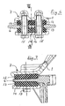
- the mounting bracket 1 and the bridge piece 6 are shown in Figs 6 and 7 , to which reference is now made. These two members are connected only via generally plate-shaped rubber elements 12 and 13. An upper rubber element 12 is arranged between the mounting bracket 1 and the bridge piece 6, whereas a lower rubber element 13 is arranged between the bridge piece 6 and a plate 14.
- the rubber elements 12 and 13 have confined positions in relation to the mounting bracket 1, the bridge piece 6 and the plate 14, in that these members have recesses for the rubber elements.
- rubber is meant to include any rubber-elastic material.
- the joint 7 is held together by means of screws 15, which in the shown case engage threads in the mounting bracket 1 and pass corresponding openings in the rubber elements 12 and 13.
- a fixed distance between the mounting bracket 1 and the plate 14 is created by means of distance sleeves 16 around the screws 15.
- the rubber elements 12 and 13 are prestressed at mounting for ensuring that they always work under a predetermined compression.
- the bridge piece 6 is provided with larger holes for ensuring its freedom to move to the necessary extent in all directions in relation to the bracket 1 and the plate 14.
- the portion of the bridge piece 6 in contact with the rubber elements 12 and 13 tapers slightly to the left in Fig 7 .
- This bridge piece portion is provided with a number of slots for obtaining an enhanced grip on the rubber.
- Figs 8a-g illustrate the relationship between the different members of the caliper under different working conditions. Only Fig 8a is provided with reference numerals for the sake of clarity.
- Fig 8a shown in Fig 8a are the bridge piece 6 with the joint 7 and the levers 8, 9 pivotally connected thereto. Pivotally connected to the left ends of the levers 8, 9 (but not shown) are the brake pad holders 4 and to the right ends the brake unit 11.
- Fig 8a illustrates the caliper at the beginning of a brake application with new, unworn brake pads 5 and with a new, unworn brake disc. Further, the brake disc is centered in relation to the caliper.
- Fig 8b is an illustration of the caliper of Fig 8a somewhat later during braking.
- Fig 8c corresponds to Fig 8a with the difference that the brake disc is axially displaced (for example 20 mm) upwards in the Figure in relation to the caliper.
- Fig 8d illustrates the situation when the brake pads 5 as well as the brake disc are worn, but the brake disc is centered in relation to the caliper.
- Fig 8e corresponds to Fig 8d but illustrates the situation when the brake pads 5 have been completely worn out.
- Fig 8f corresponds to Fig 8d but with the brake disc axially displaced upwards in the Figure in relation to the caliper.
- Fig 8g corresponds to Fig 8e but with the brake disc axially displaced upwards in the Figure in relation to the caliper.
- the shown and described disc brake caliper is provided with a mounting bracket 1, from which all other elements of the caliper are suspended and which serves for mounting the caliper to the undercarriage or bogie of the rail vehicle.
- a mounting bracket 1 from which all other elements of the caliper are suspended and which serves for mounting the caliper to the undercarriage or bogie of the rail vehicle.
Landscapes
- Engineering & Computer Science (AREA)
- General Engineering & Computer Science (AREA)
- Mechanical Engineering (AREA)
- Braking Arrangements (AREA)
Applications Claiming Priority (2)
| Application Number | Priority Date | Filing Date | Title |
|---|---|---|---|
| SE0600788A SE531450C2 (sv) | 2006-04-07 | 2006-04-07 | Skivbromscaliper |
| PCT/EP2007/002978 WO2007115738A1 (en) | 2006-04-07 | 2007-04-03 | A disc brake caliper |
Publications (2)
| Publication Number | Publication Date |
|---|---|
| EP2005019A1 EP2005019A1 (en) | 2008-12-24 |
| EP2005019B1 true EP2005019B1 (en) | 2009-11-25 |
Family
ID=38141334
Family Applications (1)
| Application Number | Title | Priority Date | Filing Date |
|---|---|---|---|
| EP07723919A Not-in-force EP2005019B1 (en) | 2006-04-07 | 2007-04-03 | A disc brake caliper |
Country Status (13)
| Country | Link |
|---|---|
| US (1) | US8006812B2 (https=) |
| EP (1) | EP2005019B1 (https=) |
| JP (1) | JP4921547B2 (https=) |
| CN (1) | CN101427043B (https=) |
| AT (1) | ATE449919T1 (https=) |
| AU (1) | AU2007236208B2 (https=) |
| BR (1) | BRPI0709762A2 (https=) |
| CA (1) | CA2647284A1 (https=) |
| DE (1) | DE602007003460D1 (https=) |
| ES (1) | ES2339397T3 (https=) |
| SE (1) | SE531450C2 (https=) |
| WO (1) | WO2007115738A1 (https=) |
| ZA (1) | ZA200808366B (https=) |
Families Citing this family (11)
| Publication number | Priority date | Publication date | Assignee | Title |
|---|---|---|---|---|
| CN102195395B (zh) * | 2010-12-27 | 2013-01-23 | 南车青岛四方机车车辆股份有限公司 | 轨道车辆直线电机悬挂装置及其方法 |
| DE102012207194A1 (de) * | 2012-04-30 | 2013-10-31 | Siemens Aktiengesellschaft | Bremseinheit für ein Fahrzeug und Fahrzeug mit einer derartigen Bremseinheit |
| EP2939899B1 (en) * | 2012-12-26 | 2020-11-25 | Nabtesco Corporation | Railway vehicle disc brake apparatus |
| DE102013213618A1 (de) | 2013-07-11 | 2015-01-15 | Siemens Aktiengesellschaft | Bremsvorrichtung |
| JP6396721B2 (ja) | 2014-08-22 | 2018-09-26 | 曙ブレーキ工業株式会社 | ディスクブレーキ装置及び鉄道用ディスクブレーキ |
| JP6467169B2 (ja) * | 2014-08-26 | 2019-02-06 | ナブテスコ株式会社 | 車両用ディスクブレーキ装置 |
| CN105365842B (zh) * | 2015-11-25 | 2017-11-03 | 中车唐山机车车辆有限公司 | 制动夹钳单元吊装结构及列车转向架 |
| DE102016103238A1 (de) * | 2016-02-24 | 2017-08-24 | Knorr-Bremse Systeme für Schienenfahrzeuge GmbH | Bremszangeneinheit |
| EP3540258B1 (en) * | 2018-03-12 | 2023-04-26 | KNORR-BREMSE Systeme für Schienenfahrzeuge GmbH | Pull rod device arrangement of a brake caliper and brake caliper |
| DE102018118517A1 (de) * | 2018-07-31 | 2020-02-06 | Knorr-Bremse Systeme für Schienenfahrzeuge GmbH | Belaghalter für eine Bremsbelaghalterung eines Schienenfahrzeugs und Bremsbelaghalterung |
| EP3753760B1 (en) * | 2019-06-21 | 2021-08-04 | C.R.F. Società Consortile per Azioni | Suspension device of a motor-vehicle wheel |
Family Cites Families (11)
| Publication number | Priority date | Publication date | Assignee | Title |
|---|---|---|---|---|
| US2479085A (en) * | 1945-06-08 | 1949-08-16 | Bettendorf Co | Railway car brake |
| US2584940A (en) * | 1949-05-14 | 1952-02-05 | American Steel Foundries | Duplex brake |
| DE1916687A1 (de) * | 1968-04-11 | 1970-10-08 | Girling Ltd | Scheibenbremse fuer Schienenfahrzeuge |
| DE2504804A1 (de) * | 1975-02-05 | 1976-08-19 | Knorr Bremse Gmbh | Scheibenbremse fuer schienenfahrzeuge |
| DE2656052C2 (de) * | 1976-12-10 | 1985-02-28 | Knorr-Bremse GmbH, 8000 München | Scheibenbremse, insbesondere für Schienenfahrzeuge |
| SE423515B (sv) * | 1980-10-16 | 1982-05-10 | Knorr Bremse Gmbh | Upphengningsorgan for en skivbromsenhet hos ett relsfordon |
| DE3821955A1 (de) * | 1988-01-22 | 1990-01-04 | Duewag Ag | Drehgestellartiges fahrwerk fuer schienenfahrzeuge |
| JP3474746B2 (ja) * | 1997-11-05 | 2003-12-08 | カヤバ工業株式会社 | 浮動型キャリパブレーキ装置 |
| JP4593840B2 (ja) * | 2001-07-24 | 2010-12-08 | カヤバ工業株式会社 | 浮動型キャリパブレーキ装置 |
| CN2520273Y (zh) * | 2002-02-27 | 2002-11-13 | 铁道科学研究院机车车辆研究所 | 一种轮装盘形制动装置 |
| DE20206648U1 (de) | 2002-04-25 | 2002-08-08 | SAB Wabco BSI Verkehrstechnik Products GmbH, 42859 Remscheid | Bremseinrichtung, insbesondere für Schienenfahrzeuge |
-
2006
- 2006-04-07 SE SE0600788A patent/SE531450C2/sv not_active IP Right Cessation
-
2007
- 2007-04-03 ES ES07723919T patent/ES2339397T3/es active Active
- 2007-04-03 ZA ZA200808366A patent/ZA200808366B/xx unknown
- 2007-04-03 CA CA002647284A patent/CA2647284A1/en not_active Abandoned
- 2007-04-03 JP JP2009503477A patent/JP4921547B2/ja not_active Expired - Fee Related
- 2007-04-03 WO PCT/EP2007/002978 patent/WO2007115738A1/en not_active Ceased
- 2007-04-03 AU AU2007236208A patent/AU2007236208B2/en not_active Ceased
- 2007-04-03 EP EP07723919A patent/EP2005019B1/en not_active Not-in-force
- 2007-04-03 CN CN2007800125147A patent/CN101427043B/zh not_active Expired - Fee Related
- 2007-04-03 DE DE602007003460T patent/DE602007003460D1/de active Active
- 2007-04-03 BR BRPI0709762-0A patent/BRPI0709762A2/pt not_active IP Right Cessation
- 2007-04-03 AT AT07723919T patent/ATE449919T1/de not_active IP Right Cessation
-
2008
- 2008-10-07 US US12/246,962 patent/US8006812B2/en not_active Expired - Fee Related
Also Published As
| Publication number | Publication date |
|---|---|
| US8006812B2 (en) | 2011-08-30 |
| CN101427043B (zh) | 2011-01-26 |
| EP2005019A1 (en) | 2008-12-24 |
| ZA200808366B (en) | 2010-01-27 |
| BRPI0709762A2 (pt) | 2011-07-26 |
| DE602007003460D1 (de) | 2010-01-07 |
| AU2007236208B2 (en) | 2011-10-06 |
| SE0600788L (sv) | 2007-10-08 |
| US20090229930A1 (en) | 2009-09-17 |
| ES2339397T3 (es) | 2010-05-19 |
| WO2007115738A1 (en) | 2007-10-18 |
| JP4921547B2 (ja) | 2012-04-25 |
| JP2009536119A (ja) | 2009-10-08 |
| AU2007236208A1 (en) | 2007-10-18 |
| CN101427043A (zh) | 2009-05-06 |
| CA2647284A1 (en) | 2007-10-18 |
| ATE449919T1 (de) | 2009-12-15 |
| SE531450C2 (sv) | 2009-04-07 |
Similar Documents
| Publication | Publication Date | Title |
|---|---|---|
| EP2005019B1 (en) | A disc brake caliper | |
| US20080060887A1 (en) | Wheel brake caliper | |
| EP2787238A1 (en) | Disc-brake device and calipers | |
| EP0046619B1 (en) | A rail vehicle disc brake arrangement | |
| EP2694350B1 (en) | A rail vehicle brake actuator with a brake block holder | |
| SE513955C2 (sv) | Rälsfordonsboggi | |
| JP4939444B2 (ja) | ディスクブレーキの防振ゴムによるブレーキトルク受け機構 | |
| EP0091151A1 (en) | A rail vehicle disc brake caliper | |
| EP0018050B1 (en) | A railway vehicle brake block holder | |
| EP0050888B1 (en) | Suspension means for a rail vehicle disc brake unit | |
| CA1230832A (en) | Block brake for rail vehicle | |
| SE517690C2 (sv) | Blockhållare för en boggibroms | |
| EP0077586B1 (en) | A railway vehicle brake block holder | |
| US3624765A (en) | Disc brake | |
| US3507364A (en) | Railway disc brakes and supporting means therefor | |
| EP1373750B1 (en) | Disc brake | |
| JP2021188635A (ja) | ブレーキキャリパ装置 | |
| JPH01224530A (ja) | 浮動キャリパ型ディスクブレーキ | |
| JP2008138737A (ja) | ディスクブレーキ | |
| EP0879751A1 (en) | Improvements in bogie trucks for rail vehicles | |
| JP2017172640A (ja) | ブレーキ装置 | |
| GB2330633A (en) | Bogie truck for rail vehicles | |
| JP2011202670A (ja) | キャリパブレーキ装置 |
Legal Events
| Date | Code | Title | Description |
|---|---|---|---|
| PUAI | Public reference made under article 153(3) epc to a published international application that has entered the european phase |
Free format text: ORIGINAL CODE: 0009012 |
|
| 17P | Request for examination filed |
Effective date: 20080924 |
|
| AK | Designated contracting states |
Kind code of ref document: A1 Designated state(s): AT BE BG CH CY CZ DE DK EE ES FI FR GB GR HU IE IS IT LI LT LU LV MC MT NL PL PT RO SE SI SK TR |
|
| GRAP | Despatch of communication of intention to grant a patent |
Free format text: ORIGINAL CODE: EPIDOSNIGR1 |
|
| GRAS | Grant fee paid |
Free format text: ORIGINAL CODE: EPIDOSNIGR3 |
|
| GRAA | (expected) grant |
Free format text: ORIGINAL CODE: 0009210 |
|
| AK | Designated contracting states |
Kind code of ref document: B1 Designated state(s): AT BE BG CH CY CZ DE DK EE ES FI FR GB GR HU IE IS IT LI LT LU LV MC MT NL PL PT RO SE SI SK TR |
|
| REG | Reference to a national code |
Ref country code: GB Ref legal event code: FG4D |
|
| REG | Reference to a national code |
Ref country code: CH Ref legal event code: EP |
|
| REG | Reference to a national code |
Ref country code: IE Ref legal event code: FG4D |
|
| REF | Corresponds to: |
Ref document number: 602007003460 Country of ref document: DE Date of ref document: 20100107 Kind code of ref document: P |
|
| REG | Reference to a national code |
Ref country code: NL Ref legal event code: VDEP Effective date: 20091125 |
|
| LTIE | Lt: invalidation of european patent or patent extension |
Effective date: 20091125 |
|
| PG25 | Lapsed in a contracting state [announced via postgrant information from national office to epo] |
Ref country code: PT Free format text: LAPSE BECAUSE OF FAILURE TO SUBMIT A TRANSLATION OF THE DESCRIPTION OR TO PAY THE FEE WITHIN THE PRESCRIBED TIME-LIMIT Effective date: 20100325 Ref country code: SE Free format text: LAPSE BECAUSE OF FAILURE TO SUBMIT A TRANSLATION OF THE DESCRIPTION OR TO PAY THE FEE WITHIN THE PRESCRIBED TIME-LIMIT Effective date: 20091125 Ref country code: LT Free format text: LAPSE BECAUSE OF FAILURE TO SUBMIT A TRANSLATION OF THE DESCRIPTION OR TO PAY THE FEE WITHIN THE PRESCRIBED TIME-LIMIT Effective date: 20091125 Ref country code: IS Free format text: LAPSE BECAUSE OF FAILURE TO SUBMIT A TRANSLATION OF THE DESCRIPTION OR TO PAY THE FEE WITHIN THE PRESCRIBED TIME-LIMIT Effective date: 20100325 Ref country code: FI Free format text: LAPSE BECAUSE OF FAILURE TO SUBMIT A TRANSLATION OF THE DESCRIPTION OR TO PAY THE FEE WITHIN THE PRESCRIBED TIME-LIMIT Effective date: 20091125 |
|
| REG | Reference to a national code |
Ref country code: ES Ref legal event code: FG2A Ref document number: 2339397 Country of ref document: ES Kind code of ref document: T3 |
|
| PG25 | Lapsed in a contracting state [announced via postgrant information from national office to epo] |
Ref country code: CY Free format text: LAPSE BECAUSE OF FAILURE TO SUBMIT A TRANSLATION OF THE DESCRIPTION OR TO PAY THE FEE WITHIN THE PRESCRIBED TIME-LIMIT Effective date: 20091125 Ref country code: LV Free format text: LAPSE BECAUSE OF FAILURE TO SUBMIT A TRANSLATION OF THE DESCRIPTION OR TO PAY THE FEE WITHIN THE PRESCRIBED TIME-LIMIT Effective date: 20091125 Ref country code: PL Free format text: LAPSE BECAUSE OF FAILURE TO SUBMIT A TRANSLATION OF THE DESCRIPTION OR TO PAY THE FEE WITHIN THE PRESCRIBED TIME-LIMIT Effective date: 20091125 Ref country code: SI Free format text: LAPSE BECAUSE OF FAILURE TO SUBMIT A TRANSLATION OF THE DESCRIPTION OR TO PAY THE FEE WITHIN THE PRESCRIBED TIME-LIMIT Effective date: 20091125 |
|
| PG25 | Lapsed in a contracting state [announced via postgrant information from national office to epo] |
Ref country code: AT Free format text: LAPSE BECAUSE OF FAILURE TO SUBMIT A TRANSLATION OF THE DESCRIPTION OR TO PAY THE FEE WITHIN THE PRESCRIBED TIME-LIMIT Effective date: 20091125 Ref country code: BE Free format text: LAPSE BECAUSE OF FAILURE TO SUBMIT A TRANSLATION OF THE DESCRIPTION OR TO PAY THE FEE WITHIN THE PRESCRIBED TIME-LIMIT Effective date: 20091125 |
|
| PG25 | Lapsed in a contracting state [announced via postgrant information from national office to epo] |
Ref country code: EE Free format text: LAPSE BECAUSE OF FAILURE TO SUBMIT A TRANSLATION OF THE DESCRIPTION OR TO PAY THE FEE WITHIN THE PRESCRIBED TIME-LIMIT Effective date: 20091125 Ref country code: RO Free format text: LAPSE BECAUSE OF FAILURE TO SUBMIT A TRANSLATION OF THE DESCRIPTION OR TO PAY THE FEE WITHIN THE PRESCRIBED TIME-LIMIT Effective date: 20091125 Ref country code: BG Free format text: LAPSE BECAUSE OF FAILURE TO SUBMIT A TRANSLATION OF THE DESCRIPTION OR TO PAY THE FEE WITHIN THE PRESCRIBED TIME-LIMIT Effective date: 20100225 Ref country code: NL Free format text: LAPSE BECAUSE OF FAILURE TO SUBMIT A TRANSLATION OF THE DESCRIPTION OR TO PAY THE FEE WITHIN THE PRESCRIBED TIME-LIMIT Effective date: 20091125 Ref country code: DK Free format text: LAPSE BECAUSE OF FAILURE TO SUBMIT A TRANSLATION OF THE DESCRIPTION OR TO PAY THE FEE WITHIN THE PRESCRIBED TIME-LIMIT Effective date: 20091125 |
|
| PG25 | Lapsed in a contracting state [announced via postgrant information from national office to epo] |
Ref country code: CZ Free format text: LAPSE BECAUSE OF FAILURE TO SUBMIT A TRANSLATION OF THE DESCRIPTION OR TO PAY THE FEE WITHIN THE PRESCRIBED TIME-LIMIT Effective date: 20091125 Ref country code: SK Free format text: LAPSE BECAUSE OF FAILURE TO SUBMIT A TRANSLATION OF THE DESCRIPTION OR TO PAY THE FEE WITHIN THE PRESCRIBED TIME-LIMIT Effective date: 20091125 |
|
| PLBE | No opposition filed within time limit |
Free format text: ORIGINAL CODE: 0009261 |
|
| STAA | Information on the status of an ep patent application or granted ep patent |
Free format text: STATUS: NO OPPOSITION FILED WITHIN TIME LIMIT |
|
| PG25 | Lapsed in a contracting state [announced via postgrant information from national office to epo] |
Ref country code: GR Free format text: LAPSE BECAUSE OF FAILURE TO SUBMIT A TRANSLATION OF THE DESCRIPTION OR TO PAY THE FEE WITHIN THE PRESCRIBED TIME-LIMIT Effective date: 20100226 |
|
| 26N | No opposition filed |
Effective date: 20100826 |
|
| PG25 | Lapsed in a contracting state [announced via postgrant information from national office to epo] |
Ref country code: MC Free format text: LAPSE BECAUSE OF NON-PAYMENT OF DUE FEES Effective date: 20100430 |
|
| PG25 | Lapsed in a contracting state [announced via postgrant information from national office to epo] |
Ref country code: IE Free format text: LAPSE BECAUSE OF NON-PAYMENT OF DUE FEES Effective date: 20100403 |
|
| PG25 | Lapsed in a contracting state [announced via postgrant information from national office to epo] |
Ref country code: IT Free format text: LAPSE BECAUSE OF NON-PAYMENT OF DUE FEES Effective date: 20100403 |
|
| PG25 | Lapsed in a contracting state [announced via postgrant information from national office to epo] |
Ref country code: MT Free format text: LAPSE BECAUSE OF FAILURE TO SUBMIT A TRANSLATION OF THE DESCRIPTION OR TO PAY THE FEE WITHIN THE PRESCRIBED TIME-LIMIT Effective date: 20091125 |
|
| REG | Reference to a national code |
Ref country code: CH Ref legal event code: PL |
|
| PG25 | Lapsed in a contracting state [announced via postgrant information from national office to epo] |
Ref country code: LI Free format text: LAPSE BECAUSE OF NON-PAYMENT OF DUE FEES Effective date: 20110430 Ref country code: CH Free format text: LAPSE BECAUSE OF NON-PAYMENT OF DUE FEES Effective date: 20110430 |
|
| PG25 | Lapsed in a contracting state [announced via postgrant information from national office to epo] |
Ref country code: LU Free format text: LAPSE BECAUSE OF NON-PAYMENT OF DUE FEES Effective date: 20100403 Ref country code: HU Free format text: LAPSE BECAUSE OF FAILURE TO SUBMIT A TRANSLATION OF THE DESCRIPTION OR TO PAY THE FEE WITHIN THE PRESCRIBED TIME-LIMIT Effective date: 20100526 |
|
| PG25 | Lapsed in a contracting state [announced via postgrant information from national office to epo] |
Ref country code: TR Free format text: LAPSE BECAUSE OF FAILURE TO SUBMIT A TRANSLATION OF THE DESCRIPTION OR TO PAY THE FEE WITHIN THE PRESCRIBED TIME-LIMIT Effective date: 20091125 |
|
| PGFP | Annual fee paid to national office [announced via postgrant information from national office to epo] |
Ref country code: ES Payment date: 20120412 Year of fee payment: 6 |
|
| PGFP | Annual fee paid to national office [announced via postgrant information from national office to epo] |
Ref country code: DE Payment date: 20130411 Year of fee payment: 7 Ref country code: GB Payment date: 20130411 Year of fee payment: 7 |
|
| PGFP | Annual fee paid to national office [announced via postgrant information from national office to epo] |
Ref country code: IT Payment date: 20130424 Year of fee payment: 7 Ref country code: FR Payment date: 20130502 Year of fee payment: 7 |
|
| REG | Reference to a national code |
Ref country code: DE Ref legal event code: R119 Ref document number: 602007003460 Country of ref document: DE |
|
| GBPC | Gb: european patent ceased through non-payment of renewal fee |
Effective date: 20140403 |
|
| REG | Reference to a national code |
Ref country code: DE Ref legal event code: R119 Ref document number: 602007003460 Country of ref document: DE Effective date: 20141101 |
|
| REG | Reference to a national code |
Ref country code: FR Ref legal event code: ST Effective date: 20141231 |
|
| PG25 | Lapsed in a contracting state [announced via postgrant information from national office to epo] |
Ref country code: DE Free format text: LAPSE BECAUSE OF NON-PAYMENT OF DUE FEES Effective date: 20141101 Ref country code: GB Free format text: LAPSE BECAUSE OF NON-PAYMENT OF DUE FEES Effective date: 20140403 |
|
| PG25 | Lapsed in a contracting state [announced via postgrant information from national office to epo] |
Ref country code: FR Free format text: LAPSE BECAUSE OF NON-PAYMENT OF DUE FEES Effective date: 20140430 |
|
| PG25 | Lapsed in a contracting state [announced via postgrant information from national office to epo] |
Ref country code: IT Free format text: LAPSE BECAUSE OF NON-PAYMENT OF DUE FEES Effective date: 20140403 |
|
| PG25 | Lapsed in a contracting state [announced via postgrant information from national office to epo] |
Ref country code: ES Free format text: LAPSE BECAUSE OF NON-PAYMENT OF DUE FEES Effective date: 20140404 |