EP2004840B1 - Sensor mit leitenden polymermaterialien - Google Patents
Sensor mit leitenden polymermaterialien Download PDFInfo
- Publication number
- EP2004840B1 EP2004840B1 EP07736103.8A EP07736103A EP2004840B1 EP 2004840 B1 EP2004840 B1 EP 2004840B1 EP 07736103 A EP07736103 A EP 07736103A EP 2004840 B1 EP2004840 B1 EP 2004840B1
- Authority
- EP
- European Patent Office
- Prior art keywords
- nanoparticles
- polyaniline
- electrode
- printed
- films
- Prior art date
- Legal status (The legal status is an assumption and is not a legal conclusion. Google has not performed a legal analysis and makes no representation as to the accuracy of the status listed.)
- Not-in-force
Links
- 239000000463 material Substances 0.000 title claims description 22
- 239000002322 conducting polymer Substances 0.000 title description 31
- 229920001940 conductive polymer Polymers 0.000 title description 31
- 239000002105 nanoparticle Substances 0.000 claims description 108
- 229920000767 polyaniline Polymers 0.000 claims description 106
- QGZKDVFQNNGYKY-UHFFFAOYSA-N Ammonia Chemical compound N QGZKDVFQNNGYKY-UHFFFAOYSA-N 0.000 claims description 87
- 229910021529 ammonia Inorganic materials 0.000 claims description 41
- -1 ammonium ions Chemical class 0.000 claims description 21
- OKTJSMMVPCPJKN-UHFFFAOYSA-N Carbon Chemical compound [C] OKTJSMMVPCPJKN-UHFFFAOYSA-N 0.000 claims description 14
- 238000004458 analytical method Methods 0.000 claims description 14
- 229910052799 carbon Inorganic materials 0.000 claims description 13
- 238000001514 detection method Methods 0.000 claims description 12
- 238000009826 distribution Methods 0.000 claims description 12
- 238000005516 engineering process Methods 0.000 claims description 9
- 238000011084 recovery Methods 0.000 claims description 8
- 239000010408 film Substances 0.000 description 94
- MHAJPDPJQMAIIY-UHFFFAOYSA-N Hydrogen peroxide Chemical compound OO MHAJPDPJQMAIIY-UHFFFAOYSA-N 0.000 description 82
- 238000000034 method Methods 0.000 description 43
- WBIQQQGBSDOWNP-UHFFFAOYSA-N 2-dodecylbenzenesulfonic acid Chemical compound CCCCCCCCCCCCC1=CC=CC=C1S(O)(=O)=O WBIQQQGBSDOWNP-UHFFFAOYSA-N 0.000 description 34
- PAYRUJLWNCNPSJ-UHFFFAOYSA-N Aniline Chemical compound NC1=CC=CC=C1 PAYRUJLWNCNPSJ-UHFFFAOYSA-N 0.000 description 34
- 230000004044 response Effects 0.000 description 32
- 108010001336 Horseradish Peroxidase Proteins 0.000 description 30
- 239000000976 ink Substances 0.000 description 30
- 239000000758 substrate Substances 0.000 description 30
- 238000007641 inkjet printing Methods 0.000 description 25
- 239000006185 dispersion Substances 0.000 description 24
- 238000007639 printing Methods 0.000 description 22
- 229920000642 polymer Polymers 0.000 description 17
- 239000002245 particle Substances 0.000 description 16
- 239000004160 Ammonium persulphate Substances 0.000 description 15
- 229910021607 Silver chloride Inorganic materials 0.000 description 15
- ROOXNKNUYICQNP-UHFFFAOYSA-N ammonium persulfate Chemical compound [NH4+].[NH4+].[O-]S(=O)(=O)OOS([O-])(=O)=O ROOXNKNUYICQNP-UHFFFAOYSA-N 0.000 description 15
- 235000019395 ammonium persulphate Nutrition 0.000 description 15
- HKZLPVFGJNLROG-UHFFFAOYSA-M silver monochloride Chemical compound [Cl-].[Ag+] HKZLPVFGJNLROG-UHFFFAOYSA-M 0.000 description 15
- 230000000694 effects Effects 0.000 description 13
- 230000008569 process Effects 0.000 description 12
- 230000015572 biosynthetic process Effects 0.000 description 11
- 230000009467 reduction Effects 0.000 description 11
- XLYOFNOQVPJJNP-UHFFFAOYSA-N water Substances O XLYOFNOQVPJJNP-UHFFFAOYSA-N 0.000 description 10
- OCKGFTQIICXDQW-ZEQRLZLVSA-N 5-[(1r)-1-hydroxy-2-[4-[(2r)-2-hydroxy-2-(4-methyl-1-oxo-3h-2-benzofuran-5-yl)ethyl]piperazin-1-yl]ethyl]-4-methyl-3h-2-benzofuran-1-one Chemical compound C1=C2C(=O)OCC2=C(C)C([C@@H](O)CN2CCN(CC2)C[C@H](O)C2=CC=C3C(=O)OCC3=C2C)=C1 OCKGFTQIICXDQW-ZEQRLZLVSA-N 0.000 description 9
- BQCADISMDOOEFD-UHFFFAOYSA-N Silver Chemical compound [Ag] BQCADISMDOOEFD-UHFFFAOYSA-N 0.000 description 9
- 238000004630 atomic force microscopy Methods 0.000 description 9
- PCHJSUWPFVWCPO-UHFFFAOYSA-N gold Chemical compound [Au] PCHJSUWPFVWCPO-UHFFFAOYSA-N 0.000 description 9
- 229910052737 gold Inorganic materials 0.000 description 9
- 239000010931 gold Substances 0.000 description 9
- 230000001965 increasing effect Effects 0.000 description 9
- 238000004519 manufacturing process Methods 0.000 description 9
- 239000000203 mixture Substances 0.000 description 9
- 229910052709 silver Inorganic materials 0.000 description 9
- 239000004332 silver Substances 0.000 description 9
- 239000002904 solvent Substances 0.000 description 9
- IJGRMHOSHXDMSA-UHFFFAOYSA-N Atomic nitrogen Chemical compound N#N IJGRMHOSHXDMSA-UHFFFAOYSA-N 0.000 description 8
- 102000004190 Enzymes Human genes 0.000 description 8
- 108090000790 Enzymes Proteins 0.000 description 8
- 230000005518 electrochemistry Effects 0.000 description 8
- 229940088598 enzyme Drugs 0.000 description 8
- 239000000047 product Substances 0.000 description 8
- 239000000126 substance Substances 0.000 description 8
- 238000002484 cyclic voltammetry Methods 0.000 description 7
- 239000007789 gas Substances 0.000 description 7
- 238000005259 measurement Methods 0.000 description 7
- 239000000243 solution Substances 0.000 description 7
- 239000012736 aqueous medium Substances 0.000 description 6
- 239000000178 monomer Substances 0.000 description 6
- 230000003647 oxidation Effects 0.000 description 6
- 238000007254 oxidation reaction Methods 0.000 description 6
- 239000008363 phosphate buffer Substances 0.000 description 6
- BASFCYQUMIYNBI-UHFFFAOYSA-N platinum Chemical compound [Pt] BASFCYQUMIYNBI-UHFFFAOYSA-N 0.000 description 6
- 241000894007 species Species 0.000 description 6
- 239000010409 thin film Substances 0.000 description 6
- NLXLAEXVIDQMFP-UHFFFAOYSA-N Ammonium chloride Substances [NH4+].[Cl-] NLXLAEXVIDQMFP-UHFFFAOYSA-N 0.000 description 5
- 230000002776 aggregation Effects 0.000 description 5
- 238000004061 bleaching Methods 0.000 description 5
- 239000000872 buffer Substances 0.000 description 5
- 230000003197 catalytic effect Effects 0.000 description 5
- 238000001816 cooling Methods 0.000 description 5
- 230000007423 decrease Effects 0.000 description 5
- 238000000502 dialysis Methods 0.000 description 5
- 238000003018 immunoassay Methods 0.000 description 5
- 239000012528 membrane Substances 0.000 description 5
- 230000002829 reductive effect Effects 0.000 description 5
- 238000003786 synthesis reaction Methods 0.000 description 5
- 229920002799 BoPET Polymers 0.000 description 4
- WQZGKKKJIJFFOK-GASJEMHNSA-N Glucose Natural products OC[C@H]1OC(O)[C@H](O)[C@@H](O)[C@@H]1O WQZGKKKJIJFFOK-GASJEMHNSA-N 0.000 description 4
- 239000005041 Mylar™ Substances 0.000 description 4
- XSQUKJJJFZCRTK-UHFFFAOYSA-N Urea Chemical compound NC(N)=O XSQUKJJJFZCRTK-UHFFFAOYSA-N 0.000 description 4
- 238000007792 addition Methods 0.000 description 4
- 238000004220 aggregation Methods 0.000 description 4
- 239000000427 antigen Substances 0.000 description 4
- 102000036639 antigens Human genes 0.000 description 4
- 108091007433 antigens Proteins 0.000 description 4
- 230000008901 benefit Effects 0.000 description 4
- 239000004202 carbamide Substances 0.000 description 4
- 238000006555 catalytic reaction Methods 0.000 description 4
- 239000008103 glucose Substances 0.000 description 4
- 229910052751 metal Inorganic materials 0.000 description 4
- 239000002184 metal Substances 0.000 description 4
- 238000012544 monitoring process Methods 0.000 description 4
- 229910052757 nitrogen Inorganic materials 0.000 description 4
- 230000003287 optical effect Effects 0.000 description 4
- 238000001314 profilometry Methods 0.000 description 4
- 102000004169 proteins and genes Human genes 0.000 description 4
- 108090000623 proteins and genes Proteins 0.000 description 4
- 230000027756 respiratory electron transport chain Effects 0.000 description 4
- 239000000523 sample Substances 0.000 description 4
- 239000004094 surface-active agent Substances 0.000 description 4
- VHUUQVKOLVNVRT-UHFFFAOYSA-N Ammonium hydroxide Chemical compound [NH4+].[OH-] VHUUQVKOLVNVRT-UHFFFAOYSA-N 0.000 description 3
- UHOVQNZJYSORNB-UHFFFAOYSA-N Benzene Chemical compound C1=CC=CC=C1 UHOVQNZJYSORNB-UHFFFAOYSA-N 0.000 description 3
- 241000188250 Idas Species 0.000 description 3
- 229920001609 Poly(3,4-ethylenedioxythiophene) Polymers 0.000 description 3
- YXFVVABEGXRONW-UHFFFAOYSA-N Toluene Chemical compound CC1=CC=CC=C1 YXFVVABEGXRONW-UHFFFAOYSA-N 0.000 description 3
- ZMANZCXQSJIPKH-UHFFFAOYSA-N Triethylamine Chemical compound CCN(CC)CC ZMANZCXQSJIPKH-UHFFFAOYSA-N 0.000 description 3
- 150000001412 amines Chemical class 0.000 description 3
- 235000011114 ammonium hydroxide Nutrition 0.000 description 3
- 238000013459 approach Methods 0.000 description 3
- 238000003556 assay Methods 0.000 description 3
- 239000012298 atmosphere Substances 0.000 description 3
- QVGXLLKOCUKJST-UHFFFAOYSA-N atomic oxygen Chemical compound [O] QVGXLLKOCUKJST-UHFFFAOYSA-N 0.000 description 3
- 230000015556 catabolic process Effects 0.000 description 3
- 230000008859 change Effects 0.000 description 3
- 238000006243 chemical reaction Methods 0.000 description 3
- 230000007797 corrosion Effects 0.000 description 3
- 238000005260 corrosion Methods 0.000 description 3
- 238000006731 degradation reaction Methods 0.000 description 3
- 238000000151 deposition Methods 0.000 description 3
- 238000011161 development Methods 0.000 description 3
- 230000018109 developmental process Effects 0.000 description 3
- LOKCTEFSRHRXRJ-UHFFFAOYSA-I dipotassium trisodium dihydrogen phosphate hydrogen phosphate dichloride Chemical compound P(=O)(O)(O)[O-].[K+].P(=O)(O)([O-])[O-].[Na+].[Na+].[Cl-].[K+].[Cl-].[Na+] LOKCTEFSRHRXRJ-UHFFFAOYSA-I 0.000 description 3
- 238000001035 drying Methods 0.000 description 3
- 238000005530 etching Methods 0.000 description 3
- 238000009472 formulation Methods 0.000 description 3
- 238000010348 incorporation Methods 0.000 description 3
- 230000007774 longterm Effects 0.000 description 3
- 150000002739 metals Chemical class 0.000 description 3
- 229910000069 nitrogen hydride Inorganic materials 0.000 description 3
- 239000001301 oxygen Substances 0.000 description 3
- 229910052760 oxygen Inorganic materials 0.000 description 3
- 238000007415 particle size distribution analysis Methods 0.000 description 3
- 150000002978 peroxides Chemical class 0.000 description 3
- 239000002953 phosphate buffered saline Substances 0.000 description 3
- 229910052697 platinum Inorganic materials 0.000 description 3
- 230000002441 reversible effect Effects 0.000 description 3
- 230000035945 sensitivity Effects 0.000 description 3
- 239000004753 textile Substances 0.000 description 3
- 238000012546 transfer Methods 0.000 description 3
- QGZKDVFQNNGYKY-UHFFFAOYSA-O Ammonium Chemical compound [NH4+] QGZKDVFQNNGYKY-UHFFFAOYSA-O 0.000 description 2
- RWSOTUBLDIXVET-UHFFFAOYSA-N Dihydrogen sulfide Chemical compound S RWSOTUBLDIXVET-UHFFFAOYSA-N 0.000 description 2
- ROSDSFDQCJNGOL-UHFFFAOYSA-N Dimethylamine Chemical compound CNC ROSDSFDQCJNGOL-UHFFFAOYSA-N 0.000 description 2
- LFQSCWFLJHTTHZ-UHFFFAOYSA-N Ethanol Chemical compound CCO LFQSCWFLJHTTHZ-UHFFFAOYSA-N 0.000 description 2
- YNQLUTRBYVCPMQ-UHFFFAOYSA-N Ethylbenzene Chemical compound CCC1=CC=CC=C1 YNQLUTRBYVCPMQ-UHFFFAOYSA-N 0.000 description 2
- 108010015776 Glucose oxidase Proteins 0.000 description 2
- 239000004366 Glucose oxidase Substances 0.000 description 2
- OAKJQQAXSVQMHS-UHFFFAOYSA-N Hydrazine Chemical compound NN OAKJQQAXSVQMHS-UHFFFAOYSA-N 0.000 description 2
- FAPWRFPIFSIZLT-UHFFFAOYSA-M Sodium chloride Chemical compound [Na+].[Cl-] FAPWRFPIFSIZLT-UHFFFAOYSA-M 0.000 description 2
- 108010046334 Urease Proteins 0.000 description 2
- 230000002378 acidificating effect Effects 0.000 description 2
- 239000012062 aqueous buffer Substances 0.000 description 2
- 238000012512 characterization method Methods 0.000 description 2
- 239000003795 chemical substances by application Substances 0.000 description 2
- DDRJAANPRJIHGJ-UHFFFAOYSA-N creatinine Chemical compound CN1CC(=O)NC1=N DDRJAANPRJIHGJ-UHFFFAOYSA-N 0.000 description 2
- 239000008367 deionised water Substances 0.000 description 2
- 229910021641 deionized water Inorganic materials 0.000 description 2
- 230000001419 dependent effect Effects 0.000 description 2
- 230000008021 deposition Effects 0.000 description 2
- 238000004090 dissolution Methods 0.000 description 2
- 239000002019 doping agent Substances 0.000 description 2
- 238000002848 electrochemical method Methods 0.000 description 2
- 239000008151 electrolyte solution Substances 0.000 description 2
- 230000002708 enhancing effect Effects 0.000 description 2
- 230000002255 enzymatic effect Effects 0.000 description 2
- 238000001704 evaporation Methods 0.000 description 2
- 230000008020 evaporation Effects 0.000 description 2
- 230000002349 favourable effect Effects 0.000 description 2
- 229940116332 glucose oxidase Drugs 0.000 description 2
- 235000019420 glucose oxidase Nutrition 0.000 description 2
- 230000012010 growth Effects 0.000 description 2
- 238000010438 heat treatment Methods 0.000 description 2
- 230000006872 improvement Effects 0.000 description 2
- AMGQUBHHOARCQH-UHFFFAOYSA-N indium;oxotin Chemical compound [In].[Sn]=O AMGQUBHHOARCQH-UHFFFAOYSA-N 0.000 description 2
- 239000003999 initiator Substances 0.000 description 2
- 238000009413 insulation Methods 0.000 description 2
- 230000002503 metabolic effect Effects 0.000 description 2
- VNWKTOKETHGBQD-UHFFFAOYSA-N methane Chemical compound C VNWKTOKETHGBQD-UHFFFAOYSA-N 0.000 description 2
- 239000000693 micelle Substances 0.000 description 2
- 238000002156 mixing Methods 0.000 description 2
- 239000007800 oxidant agent Substances 0.000 description 2
- 230000001590 oxidative effect Effects 0.000 description 2
- 238000000059 patterning Methods 0.000 description 2
- 239000012071 phase Substances 0.000 description 2
- 239000000049 pigment Substances 0.000 description 2
- 229920000139 polyethylene terephthalate Polymers 0.000 description 2
- 239000005020 polyethylene terephthalate Substances 0.000 description 2
- 229920000128 polypyrrole Polymers 0.000 description 2
- 229920000123 polythiophene Polymers 0.000 description 2
- 239000004065 semiconductor Substances 0.000 description 2
- 238000000926 separation method Methods 0.000 description 2
- 238000004528 spin coating Methods 0.000 description 2
- 238000004659 sterilization and disinfection Methods 0.000 description 2
- 238000007651 thermal printing Methods 0.000 description 2
- GETQZCLCWQTVFV-UHFFFAOYSA-N trimethylamine Chemical compound CN(C)C GETQZCLCWQTVFV-UHFFFAOYSA-N 0.000 description 2
- 239000002699 waste material Substances 0.000 description 2
- 238000004065 wastewater treatment Methods 0.000 description 2
- 239000003643 water by type Substances 0.000 description 2
- 201000001320 Atherosclerosis Diseases 0.000 description 1
- 241000894006 Bacteria Species 0.000 description 1
- BVKZGUZCCUSVTD-UHFFFAOYSA-M Bicarbonate Chemical compound OC([O-])=O BVKZGUZCCUSVTD-UHFFFAOYSA-M 0.000 description 1
- ZAMOUSCENKQFHK-UHFFFAOYSA-N Chlorine atom Chemical compound [Cl] ZAMOUSCENKQFHK-UHFFFAOYSA-N 0.000 description 1
- 208000006545 Chronic Obstructive Pulmonary Disease Diseases 0.000 description 1
- 241000196324 Embryophyta Species 0.000 description 1
- CWYNVVGOOAEACU-UHFFFAOYSA-N Fe2+ Chemical compound [Fe+2] CWYNVVGOOAEACU-UHFFFAOYSA-N 0.000 description 1
- VTLYFUHAOXGGBS-UHFFFAOYSA-N Fe3+ Chemical compound [Fe+3] VTLYFUHAOXGGBS-UHFFFAOYSA-N 0.000 description 1
- 229910002553 FeIII Inorganic materials 0.000 description 1
- 208000019693 Lung disease Diseases 0.000 description 1
- 241001465754 Metazoa Species 0.000 description 1
- 229910019093 NaOCl Inorganic materials 0.000 description 1
- 206010028980 Neoplasm Diseases 0.000 description 1
- CTQNGGLPUBDAKN-UHFFFAOYSA-N O-Xylene Chemical compound CC1=CC=CC=C1C CTQNGGLPUBDAKN-UHFFFAOYSA-N 0.000 description 1
- 108090000854 Oxidoreductases Proteins 0.000 description 1
- 102000004316 Oxidoreductases Human genes 0.000 description 1
- 229910019142 PO4 Inorganic materials 0.000 description 1
- 208000008469 Peptic Ulcer Diseases 0.000 description 1
- 102000003992 Peroxidases Human genes 0.000 description 1
- 101000971427 Plasmodium falciparum Knob-associated histidine-rich protein Proteins 0.000 description 1
- 229920000265 Polyparaphenylene Polymers 0.000 description 1
- BUGBHKTXTAQXES-UHFFFAOYSA-N Selenium Chemical compound [Se] BUGBHKTXTAQXES-UHFFFAOYSA-N 0.000 description 1
- NINIDFKCEFEMDL-UHFFFAOYSA-N Sulfur Chemical class [S] NINIDFKCEFEMDL-UHFFFAOYSA-N 0.000 description 1
- QAOWNCQODCNURD-UHFFFAOYSA-N Sulfuric acid Chemical compound OS(O)(=O)=O QAOWNCQODCNURD-UHFFFAOYSA-N 0.000 description 1
- LSNNMFCWUKXFEE-UHFFFAOYSA-N Sulfurous acid Chemical class OS(O)=O LSNNMFCWUKXFEE-UHFFFAOYSA-N 0.000 description 1
- 238000003917 TEM image Methods 0.000 description 1
- 239000002253 acid Substances 0.000 description 1
- 150000007513 acids Chemical class 0.000 description 1
- 238000005054 agglomeration Methods 0.000 description 1
- 230000032683 aging Effects 0.000 description 1
- 150000001299 aldehydes Chemical class 0.000 description 1
- 235000019270 ammonium chloride Nutrition 0.000 description 1
- 239000008346 aqueous phase Substances 0.000 description 1
- 229910052785 arsenic Inorganic materials 0.000 description 1
- RQNWIZPPADIBDY-UHFFFAOYSA-N arsenic atom Chemical compound [As] RQNWIZPPADIBDY-UHFFFAOYSA-N 0.000 description 1
- 208000006673 asthma Diseases 0.000 description 1
- 230000000443 biocontrol Effects 0.000 description 1
- 230000005540 biological transmission Effects 0.000 description 1
- 239000007844 bleaching agent Substances 0.000 description 1
- 239000013590 bulk material Substances 0.000 description 1
- 238000011088 calibration curve Methods 0.000 description 1
- 201000011510 cancer Diseases 0.000 description 1
- 230000000711 cancerogenic effect Effects 0.000 description 1
- 235000014633 carbohydrates Nutrition 0.000 description 1
- JJWKPURADFRFRB-UHFFFAOYSA-N carbonyl sulfide Chemical compound O=C=S JJWKPURADFRFRB-UHFFFAOYSA-N 0.000 description 1
- 231100000357 carcinogen Toxicity 0.000 description 1
- 239000003183 carcinogenic agent Substances 0.000 description 1
- 239000007795 chemical reaction product Substances 0.000 description 1
- 239000003153 chemical reaction reagent Substances 0.000 description 1
- 239000000460 chlorine Substances 0.000 description 1
- 229910052801 chlorine Inorganic materials 0.000 description 1
- 239000000084 colloidal system Substances 0.000 description 1
- 238000004891 communication Methods 0.000 description 1
- 230000002860 competitive effect Effects 0.000 description 1
- 238000010668 complexation reaction Methods 0.000 description 1
- 238000004590 computer program Methods 0.000 description 1
- 239000004020 conductor Substances 0.000 description 1
- 230000008602 contraction Effects 0.000 description 1
- 229940109239 creatinine Drugs 0.000 description 1
- 108010029444 creatinine deiminase Proteins 0.000 description 1
- 239000013078 crystal Substances 0.000 description 1
- 239000002178 crystalline material Substances 0.000 description 1
- 238000001723 curing Methods 0.000 description 1
- 125000004122 cyclic group Chemical group 0.000 description 1
- 238000000354 decomposition reaction Methods 0.000 description 1
- 230000003247 decreasing effect Effects 0.000 description 1
- 238000013461 design Methods 0.000 description 1
- 206010012601 diabetes mellitus Diseases 0.000 description 1
- 238000003745 diagnosis Methods 0.000 description 1
- 238000003618 dip coating Methods 0.000 description 1
- 238000007598 dipping method Methods 0.000 description 1
- 201000010099 disease Diseases 0.000 description 1
- 208000037265 diseases, disorders, signs and symptoms Diseases 0.000 description 1
- 239000004815 dispersion polymer Substances 0.000 description 1
- 235000012489 doughnuts Nutrition 0.000 description 1
- 238000001548 drop coating Methods 0.000 description 1
- 238000004043 dyeing Methods 0.000 description 1
- 238000002296 dynamic light scattering Methods 0.000 description 1
- 230000005684 electric field Effects 0.000 description 1
- 239000007772 electrode material Substances 0.000 description 1
- 238000004070 electrodeposition Methods 0.000 description 1
- 238000005868 electrolysis reaction Methods 0.000 description 1
- 239000012776 electronic material Substances 0.000 description 1
- 239000000839 emulsion Substances 0.000 description 1
- 230000007613 environmental effect Effects 0.000 description 1
- 238000003912 environmental pollution Methods 0.000 description 1
- 238000006911 enzymatic reaction Methods 0.000 description 1
- 230000001747 exhibiting effect Effects 0.000 description 1
- 238000002474 experimental method Methods 0.000 description 1
- 239000002360 explosive Substances 0.000 description 1
- 239000003337 fertilizer Substances 0.000 description 1
- 238000001914 filtration Methods 0.000 description 1
- 238000004401 flow injection analysis Methods 0.000 description 1
- 239000012530 fluid Substances 0.000 description 1
- 235000013305 food Nutrition 0.000 description 1
- 239000012634 fragment Substances 0.000 description 1
- 239000003205 fragrance Substances 0.000 description 1
- 230000008014 freezing Effects 0.000 description 1
- 238000007710 freezing Methods 0.000 description 1
- 230000006870 function Effects 0.000 description 1
- 239000003673 groundwater Substances 0.000 description 1
- 229910000037 hydrogen sulfide Inorganic materials 0.000 description 1
- 230000002209 hydrophobic effect Effects 0.000 description 1
- 230000000984 immunochemical effect Effects 0.000 description 1
- 230000001771 impaired effect Effects 0.000 description 1
- 239000010842 industrial wastewater Substances 0.000 description 1
- 238000002347 injection Methods 0.000 description 1
- 239000007924 injection Substances 0.000 description 1
- 231100001240 inorganic pollutant Toxicity 0.000 description 1
- 230000003993 interaction Effects 0.000 description 1
- 230000002427 irreversible effect Effects 0.000 description 1
- 208000017169 kidney disease Diseases 0.000 description 1
- 231100001231 less toxic Toxicity 0.000 description 1
- 239000007788 liquid Substances 0.000 description 1
- 244000144972 livestock Species 0.000 description 1
- WPBNNNQJVZRUHP-UHFFFAOYSA-L manganese(2+);methyl n-[[2-(methoxycarbonylcarbamothioylamino)phenyl]carbamothioyl]carbamate;n-[2-(sulfidocarbothioylamino)ethyl]carbamodithioate Chemical compound [Mn+2].[S-]C(=S)NCCNC([S-])=S.COC(=O)NC(=S)NC1=CC=CC=C1NC(=S)NC(=O)OC WPBNNNQJVZRUHP-UHFFFAOYSA-L 0.000 description 1
- 239000003550 marker Substances 0.000 description 1
- 230000001404 mediated effect Effects 0.000 description 1
- 230000004060 metabolic process Effects 0.000 description 1
- 229910044991 metal oxide Inorganic materials 0.000 description 1
- 150000004706 metal oxides Chemical class 0.000 description 1
- 238000012986 modification Methods 0.000 description 1
- 230000004048 modification Effects 0.000 description 1
- 239000002324 mouth wash Substances 0.000 description 1
- 229940051866 mouthwash Drugs 0.000 description 1
- 239000002114 nanocomposite Substances 0.000 description 1
- 239000002707 nanocrystalline material Substances 0.000 description 1
- 239000002086 nanomaterial Substances 0.000 description 1
- 150000002825 nitriles Chemical class 0.000 description 1
- 150000002826 nitrites Chemical class 0.000 description 1
- 229910017464 nitrogen compound Inorganic materials 0.000 description 1
- 150000002830 nitrogen compounds Chemical class 0.000 description 1
- 230000036963 noncompetitive effect Effects 0.000 description 1
- 239000011368 organic material Substances 0.000 description 1
- 150000002903 organophosphorus compounds Chemical class 0.000 description 1
- 230000036542 oxidative stress Effects 0.000 description 1
- 238000004806 packaging method and process Methods 0.000 description 1
- 230000001991 pathophysiological effect Effects 0.000 description 1
- 208000011906 peptic ulcer disease Diseases 0.000 description 1
- 108040007629 peroxidase activity proteins Proteins 0.000 description 1
- 239000000575 pesticide Substances 0.000 description 1
- 150000002989 phenols Chemical class 0.000 description 1
- NBIIXXVUZAFLBC-UHFFFAOYSA-K phosphate Chemical compound [O-]P([O-])([O-])=O NBIIXXVUZAFLBC-UHFFFAOYSA-K 0.000 description 1
- 239000010452 phosphate Substances 0.000 description 1
- 238000000053 physical method Methods 0.000 description 1
- 239000004033 plastic Substances 0.000 description 1
- 229920003023 plastic Polymers 0.000 description 1
- 239000004014 plasticizer Substances 0.000 description 1
- 238000007747 plating Methods 0.000 description 1
- 229920002805 poly(2,2'-bithiophene-5,5'-diyl) polymer Polymers 0.000 description 1
- 229920001197 polyacetylene Polymers 0.000 description 1
- 150000003071 polychlorinated biphenyls Chemical class 0.000 description 1
- 229920000015 polydiacetylene Polymers 0.000 description 1
- 229920006254 polymer film Polymers 0.000 description 1
- 238000001556 precipitation Methods 0.000 description 1
- 238000002360 preparation method Methods 0.000 description 1
- 238000012545 processing Methods 0.000 description 1
- 238000007430 reference method Methods 0.000 description 1
- 230000001172 regenerating effect Effects 0.000 description 1
- 230000001105 regulatory effect Effects 0.000 description 1
- 238000005067 remediation Methods 0.000 description 1
- 238000011160 research Methods 0.000 description 1
- 229920006395 saturated elastomer Polymers 0.000 description 1
- 238000007650 screen-printing Methods 0.000 description 1
- 230000034655 secondary growth Effects 0.000 description 1
- 229910052711 selenium Inorganic materials 0.000 description 1
- 239000011669 selenium Substances 0.000 description 1
- 239000011540 sensing material Substances 0.000 description 1
- 239000011780 sodium chloride Substances 0.000 description 1
- UKLNMMHNWFDKNT-UHFFFAOYSA-M sodium chlorite Chemical compound [Na+].[O-]Cl=O UKLNMMHNWFDKNT-UHFFFAOYSA-M 0.000 description 1
- SUKJFIGYRHOWBL-UHFFFAOYSA-N sodium hypochlorite Chemical compound [Na+].Cl[O-] SUKJFIGYRHOWBL-UHFFFAOYSA-N 0.000 description 1
- DAJSVUQLFFJUSX-UHFFFAOYSA-M sodium;dodecane-1-sulfonate Chemical compound [Na+].CCCCCCCCCCCCS([O-])(=O)=O DAJSVUQLFFJUSX-UHFFFAOYSA-M 0.000 description 1
- 239000002195 soluble material Substances 0.000 description 1
- 238000001179 sorption measurement Methods 0.000 description 1
- 238000004611 spectroscopical analysis Methods 0.000 description 1
- 239000012798 spherical particle Substances 0.000 description 1
- 230000007480 spreading Effects 0.000 description 1
- 238000003892 spreading Methods 0.000 description 1
- 230000000087 stabilizing effect Effects 0.000 description 1
- 230000001954 sterilising effect Effects 0.000 description 1
- 238000003756 stirring Methods 0.000 description 1
- 230000035882 stress Effects 0.000 description 1
- 125000001424 substituent group Chemical group 0.000 description 1
- 150000004763 sulfides Chemical class 0.000 description 1
- 239000001117 sulphuric acid Substances 0.000 description 1
- 235000011149 sulphuric acid Nutrition 0.000 description 1
- 239000006228 supernatant Substances 0.000 description 1
- 238000012360 testing method Methods 0.000 description 1
- 238000002207 thermal evaporation Methods 0.000 description 1
- 231100000331 toxic Toxicity 0.000 description 1
- 230000002588 toxic effect Effects 0.000 description 1
- 231100000419 toxicity Toxicity 0.000 description 1
- 230000001988 toxicity Effects 0.000 description 1
- 238000004627 transmission electron microscopy Methods 0.000 description 1
- 239000002351 wastewater Substances 0.000 description 1
- 238000003911 water pollution Methods 0.000 description 1
- 229920003169 water-soluble polymer Polymers 0.000 description 1
- 239000008096 xylene Substances 0.000 description 1
Images




Classifications
-
- G—PHYSICS
- G01—MEASURING; TESTING
- G01N—INVESTIGATING OR ANALYSING MATERIALS BY DETERMINING THEIR CHEMICAL OR PHYSICAL PROPERTIES
- G01N33/00—Investigating or analysing materials by specific methods not covered by groups G01N1/00 - G01N31/00
- G01N33/48—Biological material, e.g. blood, urine; Haemocytometers
- G01N33/50—Chemical analysis of biological material, e.g. blood, urine; Testing involving biospecific ligand binding methods; Immunological testing
- G01N33/53—Immunoassay; Biospecific binding assay; Materials therefor
- G01N33/543—Immunoassay; Biospecific binding assay; Materials therefor with an insoluble carrier for immobilising immunochemicals
- G01N33/54366—Apparatus specially adapted for solid-phase testing
- G01N33/54373—Apparatus specially adapted for solid-phase testing involving physiochemical end-point determination, e.g. wave-guides, FETS, gratings
- G01N33/5438—Electrodes
-
- C—CHEMISTRY; METALLURGY
- C12—BIOCHEMISTRY; BEER; SPIRITS; WINE; VINEGAR; MICROBIOLOGY; ENZYMOLOGY; MUTATION OR GENETIC ENGINEERING
- C12Q—MEASURING OR TESTING PROCESSES INVOLVING ENZYMES, NUCLEIC ACIDS OR MICROORGANISMS; COMPOSITIONS OR TEST PAPERS THEREFOR; PROCESSES OF PREPARING SUCH COMPOSITIONS; CONDITION-RESPONSIVE CONTROL IN MICROBIOLOGICAL OR ENZYMOLOGICAL PROCESSES
- C12Q1/00—Measuring or testing processes involving enzymes, nucleic acids or microorganisms; Compositions therefor; Processes of preparing such compositions
- C12Q1/001—Enzyme electrodes
-
- C—CHEMISTRY; METALLURGY
- C12—BIOCHEMISTRY; BEER; SPIRITS; WINE; VINEGAR; MICROBIOLOGY; ENZYMOLOGY; MUTATION OR GENETIC ENGINEERING
- C12Q—MEASURING OR TESTING PROCESSES INVOLVING ENZYMES, NUCLEIC ACIDS OR MICROORGANISMS; COMPOSITIONS OR TEST PAPERS THEREFOR; PROCESSES OF PREPARING SUCH COMPOSITIONS; CONDITION-RESPONSIVE CONTROL IN MICROBIOLOGICAL OR ENZYMOLOGICAL PROCESSES
- C12Q1/00—Measuring or testing processes involving enzymes, nucleic acids or microorganisms; Compositions therefor; Processes of preparing such compositions
- C12Q1/001—Enzyme electrodes
- C12Q1/005—Enzyme electrodes involving specific analytes or enzymes
- C12Q1/006—Enzyme electrodes involving specific analytes or enzymes for glucose
-
- G—PHYSICS
- G01—MEASURING; TESTING
- G01N—INVESTIGATING OR ANALYSING MATERIALS BY DETERMINING THEIR CHEMICAL OR PHYSICAL PROPERTIES
- G01N33/00—Investigating or analysing materials by specific methods not covered by groups G01N1/00 - G01N31/00
- G01N33/48—Biological material, e.g. blood, urine; Haemocytometers
- G01N33/50—Chemical analysis of biological material, e.g. blood, urine; Testing involving biospecific ligand binding methods; Immunological testing
- G01N33/84—Chemical analysis of biological material, e.g. blood, urine; Testing involving biospecific ligand binding methods; Immunological testing involving inorganic compounds or pH
-
- Y—GENERAL TAGGING OF NEW TECHNOLOGICAL DEVELOPMENTS; GENERAL TAGGING OF CROSS-SECTIONAL TECHNOLOGIES SPANNING OVER SEVERAL SECTIONS OF THE IPC; TECHNICAL SUBJECTS COVERED BY FORMER USPC CROSS-REFERENCE ART COLLECTIONS [XRACs] AND DIGESTS
- Y10—TECHNICAL SUBJECTS COVERED BY FORMER USPC
- Y10T—TECHNICAL SUBJECTS COVERED BY FORMER US CLASSIFICATION
- Y10T428/00—Stock material or miscellaneous articles
- Y10T428/24—Structurally defined web or sheet [e.g., overall dimension, etc.]
- Y10T428/24802—Discontinuous or differential coating, impregnation or bond [e.g., artwork, printing, retouched photograph, etc.]
- Y10T428/24893—Discontinuous or differential coating, impregnation or bond [e.g., artwork, printing, retouched photograph, etc.] including particulate material
Definitions
- Conducting polymer materials are a unique class of organic materials that exhibit electrical and optical properties of metals and semiconductors (Saxena & Malhotra, 2003). They offer prospects for practical applications due to their levels of conductivity, inexpensiveness, and ease of synthesis.
- polyaniline is probably the most widely studied because it has a broad range of tunable properties derived from its structural flexibility. It has potential in numerous applications including sensors, rechargeable batteries, light-emitting diodes, corrosion protection of metals and gas separation membranes.
- polyaniline has proved difficult to exploit for a number of reasons. It is insoluble in common solvents which seriously hinders its processability.
- the monomer, aniline is a carcinogen.
- PANI polyaniline
- Conducting polymers are attractive for electronic applications and using inkjet printing, ultra-thin films can be patterned with resolution up to 20-30 ⁇ m (Calvert, 2001).
- Chen et al., 2003 describes inkjet printing an all-polymer RC filter circuit using soluble conducting polyaniline and poly(3,4-ethylenedioxythiophene).
- US Patent No. 6,576,975 to Yang et al. discloses an organic semiconductor device that employed inkjet printing for patterning high quality 'buffer' layers of conducting polymer between upper and lower electrodes to regulate current flow between the electrodes.
- US Patent No. 6,762,050 to Fukushima et al. discloses the manufacture of a microsensor device where soluble conducting polymers such as polypyrrole, polythiophene and polyaniline were inkjet printed between two microelectrodes, and used for the detection of biomolecular or other organic species.
- Inkjet printing of conducting polymers described to date relies on soluble conducting polymer which has inherent disadvantages.
- the polymer When the polymer is soluble in water, nonaqueous solvents must be used for the sensor application (Ballarin et al., 2004), or alternatively, a membrane must be applied on top in order to prevent dissolution of the films in the aqueous buffer solutions that are employed (Setti et al., 2005).
- a polymer is soluble in organic media, incorporation of protein is not favourable.
- inkjet printing is very vulnerable to blockage due to solvent drying and hence a printing method that relies on rapid evaporation of solvent can be intrinsically difficult to maintain (Calvert, 2001).
- US Patent No. 6,762,050 discloses that if the polymer is insoluble in both common organic and water-based solvents, the polymer needs to be synthesised directly on the substrate, wherein monomer is printed onto oxidant-containing films.
- Prior art publications are limited to water- or organic-soluble conducting polymers such as doped polyaniline derivatives or Poly(3,4-ethylenedioxythiophene) poly(styrenesulphonate) (PEDOT/PSS). Films cast from water-soluble materials are generally unstable in aqueous media, and hence often require the use of additional materials, such as polycations, in order to render the polymer insoluble (Ngamna et al., 2005).
- Athawale and Katre describe the use of a silver polyaniline nanocomposite as a sensor for ammonia vapors.
- the invention provides use of an electrode having nanoparticles of polyaniline inkjet printed thereon as an electrochemical sensor for the detection of ammonia.
- the nanoparticles may be substantially spherical in shape.
- the size distribution of the nanoparticles may be in the range of from 1nm to 100nm, such as in the range of from 10nm to 50nm.
- the size distribution of the nanoparticles may be in the range of from 20 to 80nm, typically 30nm to 80nm.
- the nanoparticles may be inkjet printed onto the electrode using piezoelectric technology.
- the sensor may be used for chemical sensing.
- the sensor may be used for direct sensing of ammonia.
- the electrode may be a thermostable material for example a thermostable material that may undergo dynamic recovery upon the application of heat.
- compositions for printing onto a substrate comprising nanoparticles of a conducting polymer.
- the composition may be an inkjet composition for inkjet printing onto a substrate.
- the nanoparticles of the composition may be substantially spherical in shape.
- the size distribution of the nanoparticles of the composition may be in the range of from 1nm to 100nm. For example, in the range of from 10nm to 50 nm. Alternatively, the size distribution of the nanoparticles may be in the range of from 20nm to 80nm, typically 30nm to 80nm
- Also described is a method for obtaining a pattern on a substrate comprising printing nanoparticles of a conducting polymer onto the substrate.
- An ink containing nanoparticles of a conducting polymer may be printed onto a substrate.
- the nanoparticles may be formed of polyaniline.
- the printing may be inkjet printing.
- the nanoparticles may be substantially spherical in shape.
- the size distribution of the nanoparticles may be in the range of from 1nm to 100nm, such as in the range of from 10nm to 50 nm. For example, in the range of from 20nm to 80nm, typically 30nm to 80nm.
- nanoparticles of a conducting polymer are also described.
- the diameter distribution of the nanoparticles may be in the range of from 1nm to 100nm, such as from 10nm to 50nm for example, 20 to 80 nm, typically 30nm to 80nm.
- the nanoparticles may be formed of polyaniline.
- the heat source may be a stream of heated air.
- the heat source may be applied directly to the sensor.
- the auxiliary electrode may be platinum.
- the reference electrode may be Ag/AgCl.
- the nanoparticles may be formed of polyaniline.
- the electrolyte solution may be phosphate buffered saline pH6.8.
- Nanoparticles of conducting polymers offer a route to overcome issues of solubility post-deposition. Once printed on a suitable substrate, nanoparticles adhere to the surface, and are rendered insoluble in mild media. In contrast, incorporation of water-soluble protein into the conducting polymer films (by printing, or otherwise), will, in the case of doped polyaniline, attach to the polymer and not be vunerable to detachment or dissolution in buffer. Not only do nanoparticles overcome vital processibilty issues, they possess numerous other advantages over their soluble counterparts, as described above, including higher conductivity and more rapid, electrochemical switching processes.
- Inkjet printing may be performed with different ink ejection technologies, of which the most commonly used are the piezoelectric and thermal. Both thermal and piezo actuators accomplish the dispensing of pico-litre (pl) -sized droplets from the capillary nozzles of an inkjet printing head.
- the printhead In the thermal cartridge, the printhead is assembled in the ink cartridge.
- the printing head consists of a nozzle plate with several ink ejection orifices connected to resistive heater elements and placed in contact with an ink reservoir. When each individual heater element is actuated, rapid transfer of heat to a small portion of the ink located in the nozzles causes evaporation, creating a solvent bubble that leads to droplet formation.
- the ink cartridge is detachable from the printhead.
- Crystalline materials in the printhead undergo mechanical stress upon application of an electric field. A very small contraction or expansion of these crystals, confined into the nozzles, allows for a reduction of space available for the ink, thus increasing pressure and causing ejection of the drop.
- Droplet sizes in both piezo and thermal technologies vary according to the temperature gradient applied, frequency, and ink viscosity.
- Aniline was purchased from Aldrich (13,293-4), vacuum distilled and stored frozen under nitrogen. Ammonium persulphate (APS), distilled aniline, dodecylbenzene sulphonic acid (DBSA) and sodium dodecylsulphonate (SDS).
- APS Ammonium persulphate
- DBSA dodecylbenzene sulphonic acid
- SDS sodium dodecylsulphonate
- Dialysis is the separation of small solute particles from colloid particles by means of a semi-permeable membrane. Using a dialysis membrane with a cutoff point of 12,000 molecular weight (as in this instance), all species with molecular weights lower than this can be removed over time. Therefore, after dialysis for 42 hours, unreacted aniline monomer (93.13 molecular weight) would be completely removed
- the initiator molecules Ammonium Persulphate (APS)
- APS Ammonium Persulphate
- the initiator molecules are evenly distributed (by a rapid mixing in this instance), they should be consumed very quickly. Therefore secondary growth of polyaniline is very limited due to lack of available reagents. Carrying out the technique of. Huang & Kaner (2006) results in nanofibrillar formation.
- DBSA dodecylbenzenesulphonic acid
- Figure A is a schematic representation of a polyaniline nanoparticle synthesised in the DBSA micellar system as described in Example 1.
- HRP horseradish peroxidase
- PVS Polyvinylsulphonate
- the silver/silver chloride (Ag/AgCl) reference electrode was purchased from Bioanalytical Systems Ltd. (Cheshire, UK).
- the platinum mesh auxiliary electrode (29,809-3) was purchased from Aldrich.
- Gwent (C10903D14) carbon paste ink was purchased from Gwent Electronic Materials Ltd. (Gwent, UK).
- Electrodag ® PF-410S silver ink and Electrodag ® 452 SS BLUE insulation ink were purchased from Acheson Poly(ethylene) terephthalate (PET) substrates were purchased from HiFi Industrial Film Ltd (Dublin, Ireland). Indium Tin Oxide sputtered PET was purchased from CPfilms.
- the ink-jet printing system was an Epson Stylus C45 printer.
- the chip resetter was purchased from www.9to6.ie. All electrochemical protocols were performed on a CH1000 potentiostat with CH1000 software, using either cyclic voltammetry or time-based amperometric modes.
- a DEK 248 screen-printer was used for fabrication of the carbon-paste and inter-digitated array electrodes.
- Example 2 Substrates employed for inkjet printing, to include electrode substrates
- Example 2A Screen-printed electrodes were fabricated in-house using a DEK 248 according to Grennan et al. (2001). Briefly, electrodes were screen-printed onto pre-shrunk polyethylene terephthalate (PET) substrate. For the carbon paste electrodes: initially a layer of silver was deposited as the conducting path. A layer of Gwent carbon paste ink (C10903D14) was deposited as the working electrode. Finally, an insulation layer was deposited to eliminate cross-talk and to define the working electrode area (9 mm 2 ).
- PET polyethylene terephthalate
- Example 2B Screen-printed electrodes were fabricated in-house using a DEK 248 according to Grennan et al. (2001).
- IDA interdigitated array
- a layer of silver was screen-printed as the electrode layer onto pre-shrunk PET substrate.
- the resulting electrodes measured 30 mm from top to base and 24 mm across the base.
- a variety of pitch sizes were utilised, though the most commonly employed were IDAs with a digit width of 200 ⁇ m and a spacing of 1000 or 1500 ⁇ m. These dimensions were printed along the base of the electrode (i.e. 200 x 1500 for an IDA with 200 ⁇ m digits and 1500 ⁇ m spacing).
- the 200 x 1000 and 200 x 1500 IDAs had a total digit number of 17 and 12 respectively in an active area measuring approximately 20 x 20 mm.
- Example 2C Indium Tin Oxide sputtered PET
- Example 2E Gold sputtered PET
- Epson print cartridges (T036 and T037), compatible with the Epson C45 were cut open and emptied of ink and the sponge inside was removed. All colour tanks of the cartridges (black, cyan, magenta and yellow) were cleaned thoroughly with deionized water. The chip on the cartridge was then reset using the chip resetter so that the printer would read the cartridge as full. Polyaniline nanoparticle dispersions (Example 1) were then poured into a tank in the cartridge, e.g., yellow. All other tanks were filled with deionized water.
- Powerpoint® was used to draw coloured circles (3 mm diam.). The design was printed in colour, e.g., yellow, on plain printing paper (210 mm x 210 mm). Screen-printed electrodes were then affixed to the printed page where the Powerpoint® circles were aligned with the electrode area. The colour cartridge was then removed from the printer and replaced with the polyaniline-filled cartridge. Polyaniline was then printed as many times as required, on the screen-printed electrodes using 'Best Photo' mode as the printer setting.
- Electrodes modified with polyaniline nanoparticles were incorporated into a flow-cell set-up as described by Killard et al., 2001. A potential of -400 mV vs. Ag/AgCl was applied. Following the reaching of a steady state, ammonium chloride at varying concentrations was passed over the sensor at a flow rate of 400 ⁇ l min -1 for 20 s and the amperometric outputs monitored.
- Interdigitated electrodes with polyaniline nanoparticles were incorporated into a gas jar for headspace analysis.
- An Impulse XP (Honeywell Analytics) ammonia sensor was employed as the reference method. Ammonia solution was introduced into the chamber dropwise.
- the polyaniline interdigitated electrode was connected in a 2 electrode configuration and cyclic voltammetry was applied (+0.1 V to -0.1 V at 0.2 V s -1 , cycled for duration of analysis). The current was sampled at +0.1 V and -0.1 V and plotted against time, yielding an i-t plot.
- Electrodes modified with polyaniline nanoparticles were incorporated into a batch-cell set-up as described by Killard et al., 2001. A potential of -100 mV vs. Ag/AgCl was applied. Following the reaching of a steady state, a number of additions of H 2 O 2 (8 mM) were added to the cell, and the amperometric outputs monitored.
- Electrodes modified with polyaniline nanoparticles were incorporated into a flow-cell set-up as described by Killard et al., 2001. A potential of -100 mV vs. Ag/AgCl was applied. Following the reaching of a steady state, horseradish peroxidase (HRP) at varying concentrations from 5 to 0.01 ⁇ g ml -1 , were passed over with H 2 O 2 (1 mM) at a flow rate of 400 ⁇ l min -1 for 20 s and the amperometric outputs monitored.
- HRP horseradish peroxidase
- a critical property of the polyaniline nanoparticle dispersions is the particle size in concentrated solution. Dynamic light scattering was used to determine the particle sizes with the size distribution shown in Figure 1a & b. This indicates that the particle sizes in the dispersions are in the range of 10-50 nm or 20 - 80 nm. There may have been conditions such as changes in physical conditions such as temperature or slight experimental differences to result in two distinctly different size ranges. Beyond these possibilities, it is not known why there are variations in particle size. From a printing perspective, the typical pigment particle size is 100-400 nm (Magdassi & Ben Mo She, 2003) which can be printed using ink-jet printer with the nozzle diameter ca. 30-60 ⁇ m (Le, 1998).
- the particle size of polyaniline nanoparticles should be at least in the same order of magnitude to the typical pigment particle size or even smaller. Due to effects of polymer aggregation, particle sizes bigger than 1000 nm was deemed unsuitable due to the possibility of clogging the print head.
- a Transmission Electron Microscope (TEM) image of the polyaniline nanoparticles shows that the emulsion polymerisation approach used results in spherical particle formation.
- the polyaniline nanoparticles were imaged on a carbon sheet where the particles were measured to be between 30 - 80 nm ( Figure 2 ).
- a desktop Epson printer that uses piezoelectric technology was used for printing the polyaniline nanoparticles (synthesised as per Example 1). Unlike thermal printers such as Hewlett Packard printers, heat is not required for droplet formation. Thermal printing uses 'shots' of heat at temperatures around 300°C. Although the flashtime of these shots are only just 2 ⁇ s, such high temperatures could induce thermal degradation of the printing material. Piezoelectric technology does not use heat, and does not degrade the material in any way. Another important advantage is more flexible ink formulations and substrates can be used in piezo technology over thermal printing.
- Example 3 Printing of polyaniline nanoparticles (2.3 % w/v) was carried out as described herein (Example 3) using an Epson Desktop C45 printer.
- particle size within the dispersion must be several orders of magnitude smaller than the nozzle of the inkjet printhead in order to prevent clogging and blockages of the nozzle.
- the diameter of the nozzle in Epson piezo printheads is reported to be of the order of 30 ⁇ m.
- the polyaniline nanoparticles used in this research have been demonstrated to have a diameters ranging between 1nm and 100nm, such as 10 and 50 nm, 20 and 80 nm, and 30 and 80nm according to Particle Size Distribution Analysis (PSD) and hence could easily be printed on an Epson printer.
- the nanoparticle dispersions contained the surfactants SDS and DBSA that helped prevent clogging of the nozzles if any aggregation of the nanoparticles did occur in the printhead.
- Both DBSA and SDS are present in the aqueous dispersion which, as surfactants will serve to decrease the surface energy of the dispersion. Whilst not wishing to be bound by theory, it is thought that this decrease in surface energy of the dispersion assists with the piezoelectric printing and the spreading of the ink on a substrate as it is deposited to form a homogenous film.
- a major advantage of the nanoparticle dispersions that was exploited was their insolubility in aqueous media despite being deposited from an aqueous dispersion. This results in an environmentally friendly, facile method to deposit films that can be exploited for solvent sensitive applications such as bio- or immunosensing. However, it was demonstrated that although the deposited films were insoluble, the films were not stable on all substrates.
- Two conductive flexible substrates were employed for the printing of the nanoparticles - Indium Tin Oxide (ITO) (Example 2C) and screen-printed electrodes (Example 2A).
- ITO-sputtered plastic had a smooth morphology and although the nanoparticles adhered well to the substrate, the films peeled off in aqueous media.
- nanoparticles themselves maybe deposited in a number of ways - for example, but not limited to, electrochemical deposition, dip-coating, drop-coating, spin-coating, inkjet and screen-printing and roll-to-roll printing.
- Atomic Force Microscopy was used to investigate the resulting nanostructure of the inkjet printed polyaniline nanoparticulate films.
- Gold mylar was used as substrate (Example 2E) as the carbon-paste surfaces (Example 2A) proved to have too rough a morphology to visualise the nanoparticles.
- Figure 4a shows the morphology of the bare gold and the gold substrate modified with a single print of nanoparticles ( Figure 4b ) for a scan size area of 1 micron. It can be observed that the nanoparticles cover the background of the gold film.
- Figure 4c shows a film printed using 10 prints. The nodule size is much larger in this instance, probably due to increased aggregation upon drying in thicker films. Section analysis was also carried out.
- the individual nanoparticle sizes were measured in the different films.
- the maximum width of these nanoparticles is about 66 nm for 5 prints and 133 nm for 10 prints. These particle sizes are larger than what was measured by the PSD analysis, attributed to aggregation and increased agglomeration of the nanoparticles upon drying (i.e., removal of solvent). AFM tip distortion may also contribute.
- All desktop printers use mono-directional printing, where the printhead and the cartridge traverse across and back in the x-direction on a metal rod in a line recording operation, ejecting ink from nozzles according to the computer program it is in communication with.
- the substrate feeds out at a defined rate beneath the moving printhead, and takes the ink that is being printed.
- the nanoparticles were seen to be composed of lines, rather than as filled, homogeneous circles.
- a bi-directional printing method was employed, where the substrate was rotated 90° for every alternate print. This resulted in much higher coverage in the x and y direction of the surface of the electrode.
- Cyclic voltammograms were generated for multilayer films printed in the mono- and bi-directional direction ( Figure 6a ). Five films of each type were fabricated and the data shows that there are is no overall difference in the CVs between mono- and bi-directional printing. % RSD values were obtained for Peak I for a number of prints ( Figure 6b ). It was shown that when films composed of 20 or more prints, the % RSD for each of the prints was significantly lower for bi-directional than mono-directional printing, possibly due to enhanced homogenity. As a result, all further printing was carried out in the bi-directional mode.
- Electrochemistry was carried out on both types of films, and was shown to be comparable in terms of peak potentials.
- the inkjet printed film has however a CV that is much more defined at potentials lower than 400 mV.
- the inkjet printed films were estimated to be 10 times thinner than the bulk area of the drop-coated film, the peak currents of both films were approximately of equal magnitude. This allows us to estimate the volume of ink being deposited per inkjet print. Assuming 50 prints results in a film with an equivalent volume of 2.5 ⁇ l. This would mean that 50 nl are being deposited per print ( Figure 7 ).
- Nanoparticle dispersions synthesised using different ratios of aniline:APS:DBSA have all been demonstrated to be inkjet printable, however the size of the resulting nanoparticles may vary, but are all within the 'inkjet printable' range i.e. less than 1000nm.
- the polyaniline inks deviate slightly from Newtonian, showing moderately higher viscosity at low shears. Moreover, the viscosity of all of the polyaniline nanoparticle dispersions are in the suitable range for inkjet printing (0.5-40 mPa s) although it was considerably lower than the viscosity of the Epson T038 ink when shear rates lower than 500 s -1 were applied.
- Conducting polymers in particular, polyaniline, are beginning to emerge as excellent sensing materials for ammonia.
- the polymer is believed to be deprotonated by ammonia, which results in a measurable change in conduction.
- Inkjet printed films were examined as a potential sensing platform for detecting ammonium ions.
- Ammonia in equilibrium with ammonium ions, which comes from rain and snow. It is used frequently in refridgeration systems and needs to be monitored for effective cooling and for personal safety.
- Chemical fertilizers containing ammonia can stimulate the growth of plankton and be toxic for fishes. To prevent the water pollution, it is very important to monitor the level of ammonium ions.
- ammonium ions are a metabolic product in many enzymatic reactions.
- ammonium and bicarbonate ions can be produced by the metabolism of urea with enzymatic action of urease. Therefore, urea can be detected by sensing its metabolic product, i.e., ammonium ions.
- Other applications for ammonia sensing are given in Table 3.
- Inkjet printed films of polyaniline (Example 3) on a disposable screen-printed carbon-paste electrode platforms (Example 2A) provides a facile route to fabricating ammonia sensors. They can be mass-produced at extremely low cost and can provide comparable detection limits and linear ranges as commercial sensors based on metal oxides.
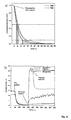
- Figure 9a & b are the amperometric responses of the inkjet printed polyaniline films (deposited on the carbon paste screen-printed electrode platform, Example 2A) to ammonium ions in solution using a flow injection setup (Example 4A). Using a flow rate of 400 ⁇ l min -1 , the response time is approximately 350 s at high concentrations of ammonia (50 ppm).
- the response time decreases to about 150 s. With further optimisation, these response times could be further reduced.
- the flow rate determines the rate at which steady state conditions are established in the flow cell. Relative humidity may also effect the response time, and this was not investigated for these experiments.
- Figure 10a shows the amperometric responses for the inkjet printed polyaniline nanoparticle films on carbon-paste screen-printed electrodes to the ammonium ion from 0 to 85 ppm.
- the potential was held at -0.4 V vs. Ag/AgCl.
- the buffer used was a phosphate buffer (0.1 M, pH 6.6).
- Figures 10b & c show the two linear ranges for NH 4 + (0-5.3 ppm and 10 - 85 ppm) within that range.
- Inkjet printed polyaniline films can also be used to detect ammonia in the gas phase (Example 4B).
- the substrate/electrode is of the form of an Interdigitated Array (IDA); screen printed using silver ink (see Example 2B).
- the polyaniline nanoparticle film is inkjet printed as described in Example 3. Once printed, these polyaniline nanoparticle-modified IDAs were heat cured at 75°C for 30 minutes.
- Various configurations and dimensions of IDA can be employed and Figure 11 shows an example of the silver IDA electrode with a 25 layer polyaniline nanoparticle film inkjet printed over it (25 x 14 mm dimension, in this example). This configuration will be referred to as a PANI-IDA electrode from here on.
- the PANI-IDA electrodes are used in a 2-electrode cell configuration (i.e. anode and cathode). At a particular potential, the current passed between the electrodes is dependent on the conductivity of the film.
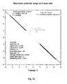
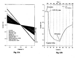
- Figure 13 shows the response of the PANI-IDA electrode when exposed to ammonia vapour.
- Figure 13a shows the current-potential raw data plot while figure 13b shows the current-time response obtained when the current is sampled at the indicated potentials.
- the stable Ohmic plot is obtained.
- the conductivity of the polyaniline rapidly decreases - as evidenced by the decreasing slope in Figure 13a and the drop in sampled current in Figure 13b .
- the electrode slowly recovers.
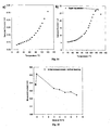
- the effect of ambient temperature on the electrode response is given in Figure 14 .
- the current measured for the PANI-IDA is seen to display a positive coefficient with temperature for the range 20 to 120°C - implying that the inherent conductivity of the polyaniline nanoparticles is increasing with temperature.
- the electrode displays good thermal stability over short time scales for temperatures up to approximately 120°C. This effect is reversible with the measured current returning to base as the temperature drops. At temperatures over 140°C, an irreversible drop in measured current is observed as the polyaniline undergoes thermal degradation. This drop in conductivity accelerates with increasing temperature.
- FIG 16a displays the response obtained for a 25 layer inkjet-printed PANI-IDA electrode when exposed to the vapour of 0.25 % ammonia solution ( ⁇ 60 ppm). From 4 replicates, it can be seen that the T50 (the time required to come to 50% of the final volume) and T90 (the time required to come to 90% of the final volume) of the sensor fall well within the 90s response required by the Instrument Society of America. In Figure 13 it can be noted that the sensor does not recover as rapidly. To this end a number of different methods of enhancing the sensor recovery were investigated. In Figure 16b , the results of the different techniques are present along with normal recovery in atmosphere.
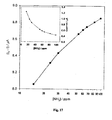
- Figure 17 shows the results of headspace analysis performed on a 25 inkjet layered PANI-IDA.
- the PANI-IDA was placed within the gas jar with a commercially available ammonia sensor (Impulse XP, Honeywell Analytics). As the ammonia concentration within the gas jar was built up, the response of the PANI-IDA and Impulse XP were noted.
- the inset of Figure 17 shows the current drop recorded for the PANI-IDA as the concentration of ammonia increases.
- the main plot shows the results obtained when the difference of measured and initial current (9.23 ⁇ A, in this case) is plotted against the log of ammonia concentration.
- the initial current, I 0 is the value measured with no ammonia present.
- a quasi-linear response is obtained with an increasing deviation observed at greater concentrations.
- the large drop in measured current observed from 0 to 15 ppm ammonia (9.23 to 1.23 ⁇ A) tends to imply concentrations below this level should be observable.
- etching baths based on sulphuric acid for various production processes, such as the manufacture of through-hole plating for multiplayer PCBs (black-hole method).
- the etching baths consist of a hydrogen peroxide component of about 25 g/l.
- concentration of hydrogen peroxide in particular, is decisive for the quality of the product, and should be kept as nearly constant as possible.
- the Jumo Corrotrode is a potentiometric sensor that is marketed for this niche market and functions as a hydrogen peroxide detector.
- H 2 O 2 analysis Another market that demands H 2 O 2 analysis is the clinical field, where exhaled breath is often monitored for H 2 O 2 . Hydrogen peroxide in the breath is indicative of lung diseases such as asthma and chronic obstructive pulmonary diseases.
- a common method to collect the exhaled breath condensate is to use a special cooling collector including a freezing cooling tube (usually cooled using ice or liquid nitrogen) and cooling machine, which has a refrigerator's circuit. Once collected, the condensate is analyzed off-line by techniques, such as spectroscopy, with assistance of peroxidase.
- H 2 O 2 is also the most valuable marker for oxidative stress, recognized as one of the major risk factors in progression of disease-related pathophysiological complications in diabetes, atherosclerosis, renal disease, cancer, aging and other condition.
- Hydrogen peroxide sensors are also needed for the development of biosensors based on enzyme oxidases. Universal Sensors market an amperometric peroxide electrode based on a platinum electrode for these types of applications at a cost of approximately $630 USD.
- Electrodes comprised of nanoparticles of polyaniline deposited (by inkjet printing (see Example 3) or other means) onto screen printed carbon-paste electrodes (Example 2A).
- the significantly enhanced sensing ability we are seeing from these materials maybe as a result of the nanostructuring. This may be attributed to the significant increases in the surface area brought about by the material.
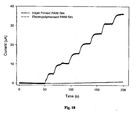
- polyaniline nanoparticle films were prepared using 20 prints. These modified electrodes were studied for their sensing properties towards H 2 O 2 . Amperograms were recorded for the reduction of H 2 O 2 at -100 mV vs Ag/AgCl in phosphate buffer, pH 6.8 (Example 4C). This was compared to the same process at an electropolymerised bulk polyaniline film (fabricated according to Grennan et al., 2001). These amperograms on the different polyaniline materials was compared in Figure 18 . The current observed for H 2 O 2 reduction was significantly higher for the inkjet printed nanoparticulate thin film than that observed on bulk polymer (approx. 100 fold). This significant increase in the current observed for H 2 O 2 reduction at the nanoparticulate films was attributed to the higher surface area to volume ratio of these materials along with their good electrical properties compared with bulk polymer.
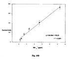
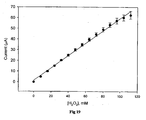
- Figure 19 shows the amperometric responses for the inkjet printed films towards H 2 O 2 , where the sensitivity was found to be 0.5419 ⁇ A mM -1 and the detection limit was found to be 1.146 ⁇ 10 -3 M based on a signal-to-noise ratio of 3.
- the analytical parameters reported here are suitable for application in a glucose biosensor, where H 2 O 2 can be exploited for glucose detection as it is a stoiciometrically equivalent product of catalysis of glucose by glucose oxidase (GOD).
- the clinical range for glucose detection in commercial products is between 1 ⁇ 10 -3 M and 3.5 ⁇ 10 -2 M (Wang et al., 2005), which falls within the linear range of this peroxide sensor.
- RSD relative standard deviation
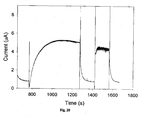
- Figure 20 demonstrates that the inkjet printed films are capable of charge transfer mediation between bound, catalyzed HRP and the electrode surface.
- the figure shows the binding curve of HRP to the electrode surface in the presence of H 2 O 2 .
- the binding if HRP is confirmed as a permanent one by the replacement of buffer with H 2 O 2 , subsequent to the HRP binding event.
- Enzymatic catalytic signal is restored showing that the catalytic signal was purely due to bound, rather than free HRP.
- enzymes such as urease or creatinine iminohydrolase, that catalyse their respective substrates, urea and creatinine, to produce ammonia.
- enzymes such as urease or creatinine iminohydrolase
- Immunoassays use the specific antigen-antibody complexation for analytical purposes. Enzyme immunoassays are well established in clinical diagnostics. For the development of hand-held devices which can be used for point of care measurements, electrochemical immunoassays are promising alternatives to existing immunochemical tests. Moreover, for opaque or optically dense matrices electrochemical methods are superior. Competitive and non-competitive electrochemical immunoassays have been developed often with enzymes as labels using conducting polymer as the diffusionless mediator.
- the patterned polyaniline films may be used as an enzyme-based immunosensor in the following theoretical situation:
- a detection antibody is immobilized to the polyaniline surface in the first instance. This surface is then exposed to an unknown concentration of antigen of interest and an enzyme- (e.g., HRP) labeled antigen. Both of these species are allowed to bind to the antibody immobilized to the surface of PANI. All excess (unbound) material is then removed and the surface of PANI is exposed to substrate (e.g., H 2 O 2 ) which is catalysed at the surface by the bound enzyme-labeled antigen (HRP).
- substrate e.g., H 2 O 2
- the polyaniline nanoparticle inkjet printed film would be used as a direct electron transfer mediator in this instance (rather than using a soluble mediator). The amount of electrochemical signal generated would be inversely proportional to the amount of 'free' unknown antigen ( Figure 21 ).
- a method to pattern high quality conducting polymer films on conducting substrates by exploiting the nanoparticulate form of the polymer for inkjet printing is illustrated.
- Aqueous dispersions of polyaniline nanoparticles were inkjet printed onto PET-based screen-printed carbon electrodes (Example 2A).
- the resulting films adhered well to the electrode surface, and electrochemistry was performed in aqueous media with no effect on the film stability.
- the polyaniline films had well-defined, reversible electrochemistry in acidic media and their use is described in two applications: direct ammonia sensing and a biosensing application using HRP.
- the results indicate that the conducting polymer nanoparticles have a wide range of applications in areas such as chemical and biosensing.
- any suitable conducting polymer material may be used.
- suitable conducting polymers are polyacetylenes, polydiacetylenes, polyparaphenylenes, polypyrroles, polythiophenes, polybithiophenes, polyisothiophenes, polyphenylenesulphides and polyanilines.
- a more comprehensive list is given in Handbook of organic conductive molecules and polymers / edited by Hari Singh Nalwa (1997 ).
Landscapes
- Health & Medical Sciences (AREA)
- Life Sciences & Earth Sciences (AREA)
- Chemical & Material Sciences (AREA)
- Engineering & Computer Science (AREA)
- Immunology (AREA)
- Organic Chemistry (AREA)
- Molecular Biology (AREA)
- Biochemistry (AREA)
- General Health & Medical Sciences (AREA)
- Biotechnology (AREA)
- Urology & Nephrology (AREA)
- Microbiology (AREA)
- Analytical Chemistry (AREA)
- Physics & Mathematics (AREA)
- Wood Science & Technology (AREA)
- Zoology (AREA)
- Hematology (AREA)
- Biomedical Technology (AREA)
- Proteomics, Peptides & Aminoacids (AREA)
- Genetics & Genomics (AREA)
- General Engineering & Computer Science (AREA)
- Bioinformatics & Cheminformatics (AREA)
- Cell Biology (AREA)
- Biophysics (AREA)
- Food Science & Technology (AREA)
- Medicinal Chemistry (AREA)
- General Physics & Mathematics (AREA)
- Pathology (AREA)
- Emergency Medicine (AREA)
- Inorganic Chemistry (AREA)
- Inks, Pencil-Leads, Or Crayons (AREA)
- Macromolecular Compounds Obtained By Forming Nitrogen-Containing Linkages In General (AREA)
Claims (16)
- Verwendung einer Elektrode, die Nanopartikel von Polyanilin aufweist, die darauf Inkjet-gedruckt sind, als elektrochemischen Sensor für den Nachweis von Ammoniak.
- Verwendung nach Anspruch 1, worin die Nanopartikel kugelförmig sind.
- Verwendung nach Anspruch 1 oder 2, worin die Größenverteilung der Nanopartikel im Bereich von 1 nm bis 100 nm liegt.
- Verwendung nach einem der Ansprüche 1 bis 3, worin die Größenverteilung der Nanopartikel im Bereich von 10 nm bis 50 nm liegt.
- Verwendung nach einem der Ansprüche 1 bis 3, worin die Größenverteilung der Nanopartikel im Bereich von 20 nm bis 80 nm liegt.
- Verwendung nach einem der Ansprüche 1 bis 3, worin die Größenverteilung der Nanopartikel im Bereich von 30 nm bis 80 nm liegt.
- Verwendung nach einem der Ansprüche 1 bis 6, worin die Nanopartikel auf die Elektrode unter Verwendung von piezoelektrischer Technologie Inkjet-gedruckt werden.
- Verwendung nach einem der Ansprüche 1 bis 7, worin die Elektrode eine siebgedruckte Elektrode ist.
- Verwendung nach Anspruch 8, worin die Elektrode eine siebgedruckte Kohlepaste-Elektrode ist.
- Verwendung nach Anspruch 9 für den Nachweis von Ammoniumionen.
- Verwendung nach Anspruch 8, worin die Elektrode ein interdigitiertes Array ist.
- Verwendung nach Anspruch 11 für den Nachweis von Ammoniak in der Gasphase.
- Verwendung nach einem der Ansprüche 1 bis 12 für die direkte Messung von Ammoniak.
- Verwendung nach einem der Ansprüche 1 bis 13, worin die Elektrode ein thermostabiles Material ist, der Sensor bei Anwendung von Wärme eine dynamische Erholung erfahren kann.
- Verwendung nach einem der Ansprüche 1 bis 14 für den Nachweis von Ammoniak in einem Kühlraum.
- Verwendung nach einem der Ansprüche 1 bis 14 für den Nachweis von Ammoniak in der Atemanalyse.
Applications Claiming Priority (2)
| Application Number | Priority Date | Filing Date | Title |
|---|---|---|---|
| IE20060288 | 2006-04-13 | ||
| PCT/IE2007/000047 WO2007119229A1 (en) | 2006-04-13 | 2007-04-13 | Sensor comprising conducting polymer materials |
Publications (2)
| Publication Number | Publication Date |
|---|---|
| EP2004840A1 EP2004840A1 (de) | 2008-12-24 |
| EP2004840B1 true EP2004840B1 (de) | 2014-10-29 |
Family
ID=38220257
Family Applications (1)
| Application Number | Title | Priority Date | Filing Date |
|---|---|---|---|
| EP07736103.8A Not-in-force EP2004840B1 (de) | 2006-04-13 | 2007-04-13 | Sensor mit leitenden polymermaterialien |
Country Status (7)
| Country | Link |
|---|---|
| US (1) | US20100000883A1 (de) |
| EP (1) | EP2004840B1 (de) |
| JP (1) | JP2009533674A (de) |
| CN (1) | CN101466845A (de) |
| AU (1) | AU2007237821A1 (de) |
| IE (1) | IE20070269A1 (de) |
| WO (1) | WO2007119229A1 (de) |
Families Citing this family (35)
| Publication number | Priority date | Publication date | Assignee | Title |
|---|---|---|---|---|
| US20100089772A1 (en) * | 2006-11-10 | 2010-04-15 | Deshusses Marc A | Nanomaterial-based gas sensors |
| US20110174614A1 (en) * | 2008-06-16 | 2011-07-21 | Itamar Willner | Electrode, method and system for determining an analyte in a liquid medium |
| DE112009005088A5 (de) * | 2009-07-21 | 2012-10-04 | Heiko Schwertner | Verfahren unter der verwendung von non impact druckmethoden zusammen mit druckflüssigkeiten, die aktive biologische moleküle enthalten, zur produktion von sensoren und komplexen analytischen systemen. |
| TWI426262B (zh) * | 2010-01-18 | 2014-02-11 | Univ Yuanpei | Application of Color Image Analysis in Screen Printing Carbon Electrode |
| CN101793861B (zh) * | 2010-03-26 | 2013-01-09 | 武汉工程大学 | 聚苯胺-海藻酸-离子液体-酶复合膜修饰电极的制备方法 |
| US8476079B2 (en) * | 2010-04-30 | 2013-07-02 | Abbott Point Of Care Inc. | Reagents for reducing leukocyte interference in immunoassays |
| KR101942025B1 (ko) | 2010-08-20 | 2019-01-24 | 로디아 오퍼레이션스 | 전기적 전도성 중합체를 포함하는 막 |
| US10451598B2 (en) * | 2010-09-10 | 2019-10-22 | The Trustees Of Dartmouth College | Devices for detecting airborne contaminants, and associated methods |
| US11366077B2 (en) | 2010-09-10 | 2022-06-21 | The Trustees Of Dartmouth College | Systems, sensing devices and methods for detection of airborne contaminants |
| NL2005714C2 (en) * | 2010-11-18 | 2012-05-22 | Senzair B V | Device and method for measuring biomarkers. |
| JP6022480B2 (ja) | 2011-02-04 | 2016-11-09 | カウンシル オブ サイエンティフィック アンド インダストリアル リサーチ | 分子インプリント導電性ポリマフィルム付き水性アミノ酸センサー |
| US20130087467A1 (en) * | 2011-06-24 | 2013-04-11 | Hongjun Yang | High-performance analytical instrument and method |
| US9228988B2 (en) | 2011-08-31 | 2016-01-05 | The Trustees Of Dartmouth College | Molecularly imprinted polymers for detection of contaminants |
| US20140299468A1 (en) * | 2012-06-25 | 2014-10-09 | Hongjun Yang | High-Performance Analytical Instrument and Method |
| GB2506426B (en) * | 2012-09-28 | 2016-03-23 | Agform Ltd | Composition |
| GB2506863A (en) * | 2012-10-09 | 2014-04-16 | Univ Dublin City | System and method for analysing and measuring ammonia levels in a sample |
| CN103395311B (zh) * | 2013-08-15 | 2015-05-20 | 中国科学院新疆理化技术研究所 | 一种微珠结晶核的制备方法 |
| CN105899947A (zh) * | 2013-09-04 | 2016-08-24 | 克雷多生物医学私人有限公司 | 分析测试装置、试剂盒和使用方法 |
| RU2543687C1 (ru) * | 2013-10-03 | 2015-03-10 | Федеральное государственное бюджетное образовательное учреждение высшего профессионального образования "Воронежский государственный университет инженерных технологий" (ФГБОУ ВПО "ВГУИТ") | Способ оценки качества азотсодержащих минеральных удобрений с использованием пьезосенсоров |
| US9896772B2 (en) | 2014-03-13 | 2018-02-20 | Innosense Llc | Modular chemiresistive sensor |
| US12345680B1 (en) | 2014-03-13 | 2025-07-01 | Innosense Corporation | Modular chemiresistive sensor for real-time ethylene monitoring |
| US10274451B2 (en) | 2015-02-18 | 2019-04-30 | Santa Clara University | Affordable electrochemical detection of environmental contaminants |
| DE102015005781A1 (de) * | 2015-05-08 | 2016-11-10 | Forschungszentrum Jülich GmbH | Verfahren zur Herstellung einer Vorrichtung zum elektrochemischen Nachweis von Molekülen mittels Redox-Cycling, sowie Vorrichtung hierzu und deren Verwendung |
| CN105353015B (zh) * | 2015-12-02 | 2019-04-12 | 厦门大学 | 一种聚二氧乙烯噻吩复合膜的制备方法及应用 |
| US20180100601A1 (en) * | 2016-10-08 | 2018-04-12 | Zepto Life Technology, LLC | Electrolytic membrane valve |
| CN108802135B (zh) * | 2018-07-13 | 2020-12-22 | 复旦大学 | 以有机半导体为光敏材料的液体粘度传感器及其制备方法 |
| CN110108759A (zh) * | 2019-05-14 | 2019-08-09 | 电子科技大学 | 一种基于聚苯胺/半导体金属氧化物纳米复合薄膜的呼吸氨气传感器及其制备方法 |
| JP7391540B2 (ja) | 2019-05-31 | 2023-12-05 | 浜松ホトニクス株式会社 | 匂いセンサ及び匂い検出方法 |
| CN110632126A (zh) * | 2019-09-04 | 2019-12-31 | 东华大学 | 一种有机磷化合物传感器及其制备方法 |
| CN110646472A (zh) * | 2019-09-10 | 2020-01-03 | 中国科学院宁波材料技术与工程研究所 | 以聚吡咯复合柔性膜为基的高效氨气传感器及其制备 |
| CN117337199A (zh) * | 2021-04-28 | 2024-01-02 | 3M创新有限公司 | 传感器装置 |
| CN114316223B (zh) * | 2021-12-31 | 2022-09-27 | 华中科技大学 | 一种导电聚乙烯二氧噻吩的醇分散液及其制备方法和应用 |
| US12461051B2 (en) * | 2022-03-08 | 2025-11-04 | Ut-Battelle, Llc | Gas sensor and method of manufacture |
| KR102642598B1 (ko) * | 2022-03-30 | 2024-03-04 | 재단법인대구경북과학기술원 | 투명 전극 및 광열층의 동시 패터닝 방법 및 이를 통하여 제조된 투명 전극 구조체 |
| CN117705887A (zh) * | 2022-09-07 | 2024-03-15 | 中国科学院大连化学物理研究所 | 一种金修饰的聚苯胺作为传感器检测三乙胺的方法 |
Family Cites Families (14)
| Publication number | Priority date | Publication date | Assignee | Title |
|---|---|---|---|---|
| EP0398286A3 (de) * | 1989-05-18 | 1991-09-25 | Nisshinbo Industries, Inc. | Ammoniak-Fühler |
| US5879631A (en) * | 1996-04-30 | 1999-03-09 | Manning System, Inc. | Gas detection system and method |
| JP2000033712A (ja) * | 1997-09-30 | 2000-02-02 | Seiko Epson Corp | マイクロセンサーデバイス作成方法及びそれを用いた液体機能評価方法 |
| US6501587B1 (en) * | 2000-09-27 | 2002-12-31 | Board Of Regents, The University Of Texas System | Method of creating color-changing displays |
| US6576957B2 (en) * | 2000-12-31 | 2003-06-10 | Texas Instruments Incorporated | Etch-stopped SOI back-gate contact |
| IL148468A (en) * | 2002-03-03 | 2012-12-31 | Exalenz Bioscience Ltd | Breath collection system |
| KR100479415B1 (ko) * | 2002-06-08 | 2005-03-30 | 학교법인 한양학원 | 표면개질된 티탄산바륨의 제조방법 및 적층 세라믹 콘덴서 제조용 슬러리의 제조방법 |
| US7317047B2 (en) * | 2002-09-24 | 2008-01-08 | E.I. Du Pont De Nemours And Company | Electrically conducting organic polymer/nanoparticle composites and methods for use thereof |
| GB0229191D0 (en) * | 2002-12-14 | 2003-01-22 | Plastic Logic Ltd | Embossing of polymer devices |
| IE20040203A1 (en) | 2003-03-28 | 2004-10-06 | Trinity College Dublin | Silver nanoparticle sensor |
| US7399400B2 (en) * | 2003-09-30 | 2008-07-15 | Nano-Proprietary, Inc. | Nanobiosensor and carbon nanotube thin film transistors |
| DE602004021679D1 (de) * | 2004-06-30 | 2009-08-06 | St Microelectronics Srl | Sensor mit tintenstrahlgedrucktem aktiven Film und Verfahren zur Herstellung des Sensors |
| US7367860B2 (en) * | 2004-07-06 | 2008-05-06 | Teco Nanotech Co., Ltd. | Sintering method for carbon nanotube cathode of field-emission display |
| TWI456774B (zh) * | 2010-12-01 | 2014-10-11 | Ind Tech Res Inst | 可塗佈太陽光電電變色元件及模組 |
-
2007
- 2007-04-13 IE IE20070269A patent/IE20070269A1/en not_active IP Right Cessation
- 2007-04-13 WO PCT/IE2007/000047 patent/WO2007119229A1/en not_active Ceased
- 2007-04-13 US US12/226,223 patent/US20100000883A1/en not_active Abandoned
- 2007-04-13 JP JP2009504893A patent/JP2009533674A/ja not_active Withdrawn
- 2007-04-13 AU AU2007237821A patent/AU2007237821A1/en not_active Abandoned
- 2007-04-13 EP EP07736103.8A patent/EP2004840B1/de not_active Not-in-force
- 2007-04-13 CN CN200780021969.5A patent/CN101466845A/zh active Pending
Non-Patent Citations (1)
| Title |
|---|
| JOURNAL OF METASTABLE AND NANOCRYSTALLINE MATERIALS: "Ag Dispersed Conducting Polyaniline Nanocomposite as a Selective Sensor for Ammonia", JOURNAL OF METASTABLE AND NANOCRYSTALLINE MATERIALS, TRANS TECH PUBLICATIONS LTD, UETIKON-ZURICH, CH, vol. 23, 1 January 2005 (2005-01-01), pages 323 - 326, XP009149833, ISSN: 1422-6375 * |
Also Published As
| Publication number | Publication date |
|---|---|
| EP2004840A1 (de) | 2008-12-24 |
| AU2007237821A1 (en) | 2007-10-25 |
| WO2007119229A1 (en) | 2007-10-25 |
| IE20070269A1 (en) | 2008-12-10 |
| CN101466845A (zh) | 2009-06-24 |
| US20100000883A1 (en) | 2010-01-07 |
| JP2009533674A (ja) | 2009-09-17 |
Similar Documents
| Publication | Publication Date | Title |
|---|---|---|
| US20100000883A1 (en) | Sensor Comprising Conducting Polymer Materials | |
| Crowley et al. | Printing polyaniline for sensor applications | |
| Thakur et al. | Recent trends in nanostructured carbon-based electrochemical sensors for the detection and remediation of persistent toxic substances in real-time analysis | |
| Ahmed et al. | Electrochemical sensor based on PEDOT/CNTs-graphene oxide for simultaneous determination of hazardous hydroquinone, catechol, and nitrite in real water samples | |
| Määttänen et al. | A low-cost paper-based inkjet-printed platform for electrochemical analyses | |
| Morrin et al. | The fabrication and characterization of inkjet-printed polyaniline nanoparticle films | |
| Mohamad Nor et al. | Recent advancement in disposable electrode modified with nanomaterials for electrochemical heavy metal sensors | |
| Shu et al. | Self-referenced smartphone imaging for visual screening of H2S using Cu x O-polypyrrole conductive aerogel doped with graphene oxide framework | |
| Crowley et al. | An aqueous ammonia sensor based on an inkjet-printed polyaniline nanoparticle-modified electrode | |
| Cui et al. | Electrochemical sensing of heavy metal ions with inorganic, organic and bio-materials | |
| Setti et al. | An HRP-based amperometric biosensor fabricated by thermal inkjet printing | |
| Liu et al. | Processable enzyme-hybrid conductive polymer composites for electrochemical biosensing | |
| Zanardi et al. | Polythiophenes and polythiophene-based composites in amperometric sensing | |
| Ozsoz | Electrochemical DNA biosensors | |
| Sahin et al. | Electrooxidation of NADH on modified screen-printed electrodes: effects of conducting polymer and nanomaterials | |
| Soum et al. | Programmable contact printing using ballpoint pens with a digital plotter for patterning electrodes on paper | |
| Obeid et al. | Designs and materials of electrodes for electrochemical sensors | |
| Choudhry et al. | Next generation screen printed electrochemical platforms: Non-enzymatic sensing of carbohydrates using copper (II) oxide screen printed electrodes | |
| Shiraishi et al. | Electrochemical detection of E. coli 16S rDNA sequence using air-plasma-activated fullerene-impregnated screen printed electrodes | |
| Ramachandran et al. | An overview of fabricating nanostructured electrode materials for biosensor applications | |
| Tran et al. | Electrochemically Effective Surface Area of a Polyaniline Nanowire‐Based Platinum Microelectrode and Development of an Electrochemical DNA Sensor | |
| Nellaiappan et al. | Chemical, gas and optical sensors based on conducting polymers | |
| Solanki et al. | Horse radish peroxidase immobilized polyaniline for hydrogen peroxide sensor | |
| Morrin | Inkjet printed electrochemical sensors | |
| Chauhan et al. | Nanobiosensors for monitoring soil and water health |
Legal Events
| Date | Code | Title | Description |
|---|---|---|---|
| PUAI | Public reference made under article 153(3) epc to a published international application that has entered the european phase |
Free format text: ORIGINAL CODE: 0009012 |
|
| 17P | Request for examination filed |
Effective date: 20081021 |
|
| AK | Designated contracting states |
Kind code of ref document: A1 Designated state(s): AT BE BG CH CY CZ DE DK EE ES FI FR GB GR HU IE IS IT LI LT LU LV MC MT NL PL PT RO SE SI SK TR |
|
| RIN1 | Information on inventor provided before grant (corrected) |
Inventor name: KILLARD, ANTHONY, J. Inventor name: MOULTON, SIMON, EDWARD Inventor name: SMYTH, MALCOLM Inventor name: NGAMNA, ORAWAN Inventor name: MORRIN, AOIFE Inventor name: WALLACE, GORDON, GEORGE Inventor name: CROWLEY, KARL |
|
| 17Q | First examination report despatched |
Effective date: 20090629 |
|
| DAX | Request for extension of the european patent (deleted) | ||
| REG | Reference to a national code |
Ref country code: DE Ref legal event code: R079 Ref document number: 602007039033 Country of ref document: DE Free format text: PREVIOUS MAIN CLASS: C12Q0001000000 Ipc: G01N0033543000 |
|
| GRAP | Despatch of communication of intention to grant a patent |
Free format text: ORIGINAL CODE: EPIDOSNIGR1 |
|
| RIC1 | Information provided on ipc code assigned before grant |
Ipc: G01N 33/543 20060101AFI20140423BHEP Ipc: G01N 33/84 20060101ALI20140423BHEP Ipc: C12Q 1/00 20060101ALI20140423BHEP |
|
| INTG | Intention to grant announced |
Effective date: 20140523 |
|
| GRAS | Grant fee paid |
Free format text: ORIGINAL CODE: EPIDOSNIGR3 |
|
| GRAA | (expected) grant |
Free format text: ORIGINAL CODE: 0009210 |
|
| AK | Designated contracting states |
Kind code of ref document: B1 Designated state(s): AT BE BG CH CY CZ DE DK EE ES FI FR GB GR HU IE IS IT LI LT LU LV MC MT NL PL PT RO SE SI SK TR |
|
| REG | Reference to a national code |
Ref country code: GB Ref legal event code: FG4D |
|
| REG | Reference to a national code |
Ref country code: CH Ref legal event code: EP |
|
| REG | Reference to a national code |
Ref country code: AT Ref legal event code: REF Ref document number: 693834 Country of ref document: AT Kind code of ref document: T Effective date: 20141115 |
|
| REG | Reference to a national code |
Ref country code: IE Ref legal event code: FG4D |
|
| REG | Reference to a national code |
Ref country code: DE Ref legal event code: R096 Ref document number: 602007039033 Country of ref document: DE Effective date: 20141211 |
|
| REG | Reference to a national code |
Ref country code: AT Ref legal event code: MK05 Ref document number: 693834 Country of ref document: AT Kind code of ref document: T Effective date: 20141029 |
|
| REG | Reference to a national code |
Ref country code: NL Ref legal event code: VDEP Effective date: 20141029 |
|
| REG | Reference to a national code |
Ref country code: LT Ref legal event code: MG4D |
|
| PG25 | Lapsed in a contracting state [announced via postgrant information from national office to epo] |
Ref country code: PT Free format text: LAPSE BECAUSE OF FAILURE TO SUBMIT A TRANSLATION OF THE DESCRIPTION OR TO PAY THE FEE WITHIN THE PRESCRIBED TIME-LIMIT Effective date: 20150302 Ref country code: ES Free format text: LAPSE BECAUSE OF FAILURE TO SUBMIT A TRANSLATION OF THE DESCRIPTION OR TO PAY THE FEE WITHIN THE PRESCRIBED TIME-LIMIT Effective date: 20141029 Ref country code: FI Free format text: LAPSE BECAUSE OF FAILURE TO SUBMIT A TRANSLATION OF THE DESCRIPTION OR TO PAY THE FEE WITHIN THE PRESCRIBED TIME-LIMIT Effective date: 20141029 Ref country code: LT Free format text: LAPSE BECAUSE OF FAILURE TO SUBMIT A TRANSLATION OF THE DESCRIPTION OR TO PAY THE FEE WITHIN THE PRESCRIBED TIME-LIMIT Effective date: 20141029 Ref country code: IS Free format text: LAPSE BECAUSE OF FAILURE TO SUBMIT A TRANSLATION OF THE DESCRIPTION OR TO PAY THE FEE WITHIN THE PRESCRIBED TIME-LIMIT Effective date: 20150228 Ref country code: NL Free format text: LAPSE BECAUSE OF FAILURE TO SUBMIT A TRANSLATION OF THE DESCRIPTION OR TO PAY THE FEE WITHIN THE PRESCRIBED TIME-LIMIT Effective date: 20141029 |
|
| PG25 | Lapsed in a contracting state [announced via postgrant information from national office to epo] |
Ref country code: PL Free format text: LAPSE BECAUSE OF FAILURE TO SUBMIT A TRANSLATION OF THE DESCRIPTION OR TO PAY THE FEE WITHIN THE PRESCRIBED TIME-LIMIT Effective date: 20141029 Ref country code: CY Free format text: LAPSE BECAUSE OF FAILURE TO SUBMIT A TRANSLATION OF THE DESCRIPTION OR TO PAY THE FEE WITHIN THE PRESCRIBED TIME-LIMIT Effective date: 20141029 Ref country code: AT Free format text: LAPSE BECAUSE OF FAILURE TO SUBMIT A TRANSLATION OF THE DESCRIPTION OR TO PAY THE FEE WITHIN THE PRESCRIBED TIME-LIMIT Effective date: 20141029 Ref country code: LV Free format text: LAPSE BECAUSE OF FAILURE TO SUBMIT A TRANSLATION OF THE DESCRIPTION OR TO PAY THE FEE WITHIN THE PRESCRIBED TIME-LIMIT Effective date: 20141029 Ref country code: GR Free format text: LAPSE BECAUSE OF FAILURE TO SUBMIT A TRANSLATION OF THE DESCRIPTION OR TO PAY THE FEE WITHIN THE PRESCRIBED TIME-LIMIT Effective date: 20150130 Ref country code: SE Free format text: LAPSE BECAUSE OF FAILURE TO SUBMIT A TRANSLATION OF THE DESCRIPTION OR TO PAY THE FEE WITHIN THE PRESCRIBED TIME-LIMIT Effective date: 20141029 |
|
| REG | Reference to a national code |
Ref country code: DE Ref legal event code: R097 Ref document number: 602007039033 Country of ref document: DE |
|
| PG25 | Lapsed in a contracting state [announced via postgrant information from national office to epo] |
Ref country code: CZ Free format text: LAPSE BECAUSE OF FAILURE TO SUBMIT A TRANSLATION OF THE DESCRIPTION OR TO PAY THE FEE WITHIN THE PRESCRIBED TIME-LIMIT Effective date: 20141029 Ref country code: DK Free format text: LAPSE BECAUSE OF FAILURE TO SUBMIT A TRANSLATION OF THE DESCRIPTION OR TO PAY THE FEE WITHIN THE PRESCRIBED TIME-LIMIT Effective date: 20141029 Ref country code: SK Free format text: LAPSE BECAUSE OF FAILURE TO SUBMIT A TRANSLATION OF THE DESCRIPTION OR TO PAY THE FEE WITHIN THE PRESCRIBED TIME-LIMIT Effective date: 20141029 Ref country code: EE Free format text: LAPSE BECAUSE OF FAILURE TO SUBMIT A TRANSLATION OF THE DESCRIPTION OR TO PAY THE FEE WITHIN THE PRESCRIBED TIME-LIMIT Effective date: 20141029 Ref country code: RO Free format text: LAPSE BECAUSE OF FAILURE TO SUBMIT A TRANSLATION OF THE DESCRIPTION OR TO PAY THE FEE WITHIN THE PRESCRIBED TIME-LIMIT Effective date: 20141029 |
|
| PG25 | Lapsed in a contracting state [announced via postgrant information from national office to epo] |
Ref country code: IT Free format text: LAPSE BECAUSE OF FAILURE TO SUBMIT A TRANSLATION OF THE DESCRIPTION OR TO PAY THE FEE WITHIN THE PRESCRIBED TIME-LIMIT Effective date: 20141029 |
|
| PLBE | No opposition filed within time limit |
Free format text: ORIGINAL CODE: 0009261 |
|
| STAA | Information on the status of an ep patent application or granted ep patent |
Free format text: STATUS: NO OPPOSITION FILED WITHIN TIME LIMIT |
|
| 26N | No opposition filed |
Effective date: 20150730 |
|
| PG25 | Lapsed in a contracting state [announced via postgrant information from national office to epo] |
Ref country code: MC Free format text: LAPSE BECAUSE OF FAILURE TO SUBMIT A TRANSLATION OF THE DESCRIPTION OR TO PAY THE FEE WITHIN THE PRESCRIBED TIME-LIMIT Effective date: 20141029 Ref country code: LU Free format text: LAPSE BECAUSE OF FAILURE TO SUBMIT A TRANSLATION OF THE DESCRIPTION OR TO PAY THE FEE WITHIN THE PRESCRIBED TIME-LIMIT Effective date: 20150413 |
|
| REG | Reference to a national code |
Ref country code: CH Ref legal event code: PL |
|
| REG | Reference to a national code |
Ref country code: IE Ref legal event code: MM4A |
|
| PG25 | Lapsed in a contracting state [announced via postgrant information from national office to epo] |
Ref country code: LI Free format text: LAPSE BECAUSE OF NON-PAYMENT OF DUE FEES Effective date: 20150430 Ref country code: CH Free format text: LAPSE BECAUSE OF NON-PAYMENT OF DUE FEES Effective date: 20150430 |
|
| PG25 | Lapsed in a contracting state [announced via postgrant information from national office to epo] |
Ref country code: SI Free format text: LAPSE BECAUSE OF FAILURE TO SUBMIT A TRANSLATION OF THE DESCRIPTION OR TO PAY THE FEE WITHIN THE PRESCRIBED TIME-LIMIT Effective date: 20141029 |
|
| REG | Reference to a national code |
Ref country code: FR Ref legal event code: PLFP Year of fee payment: 10 |
|
| PG25 | Lapsed in a contracting state [announced via postgrant information from national office to epo] |
Ref country code: IE Free format text: LAPSE BECAUSE OF NON-PAYMENT OF DUE FEES Effective date: 20150413 |
|
| PG25 | Lapsed in a contracting state [announced via postgrant information from national office to epo] |
Ref country code: MT Free format text: LAPSE BECAUSE OF FAILURE TO SUBMIT A TRANSLATION OF THE DESCRIPTION OR TO PAY THE FEE WITHIN THE PRESCRIBED TIME-LIMIT Effective date: 20141029 |
|
| REG | Reference to a national code |
Ref country code: FR Ref legal event code: PLFP Year of fee payment: 11 |
|
| PG25 | Lapsed in a contracting state [announced via postgrant information from national office to epo] |
Ref country code: HU Free format text: LAPSE BECAUSE OF FAILURE TO SUBMIT A TRANSLATION OF THE DESCRIPTION OR TO PAY THE FEE WITHIN THE PRESCRIBED TIME-LIMIT; INVALID AB INITIO Effective date: 20070413 Ref country code: BG Free format text: LAPSE BECAUSE OF FAILURE TO SUBMIT A TRANSLATION OF THE DESCRIPTION OR TO PAY THE FEE WITHIN THE PRESCRIBED TIME-LIMIT Effective date: 20141029 |
|
| PG25 | Lapsed in a contracting state [announced via postgrant information from national office to epo] |
Ref country code: TR Free format text: LAPSE BECAUSE OF FAILURE TO SUBMIT A TRANSLATION OF THE DESCRIPTION OR TO PAY THE FEE WITHIN THE PRESCRIBED TIME-LIMIT Effective date: 20141029 |
|
| PG25 | Lapsed in a contracting state [announced via postgrant information from national office to epo] |
Ref country code: BE Free format text: LAPSE BECAUSE OF FAILURE TO SUBMIT A TRANSLATION OF THE DESCRIPTION OR TO PAY THE FEE WITHIN THE PRESCRIBED TIME-LIMIT Effective date: 20141029 |
|
| REG | Reference to a national code |
Ref country code: FR Ref legal event code: PLFP Year of fee payment: 12 |
|
| PGFP | Annual fee paid to national office [announced via postgrant information from national office to epo] |
Ref country code: FR Payment date: 20230329 Year of fee payment: 17 |
|
| PGFP | Annual fee paid to national office [announced via postgrant information from national office to epo] |
Ref country code: GB Payment date: 20230316 Year of fee payment: 17 |
|
| P01 | Opt-out of the competence of the unified patent court (upc) registered |
Effective date: 20230320 |
|
| PGFP | Annual fee paid to national office [announced via postgrant information from national office to epo] |
Ref country code: DE Payment date: 20230403 Year of fee payment: 17 |
|
| REG | Reference to a national code |
Ref country code: DE Ref legal event code: R119 Ref document number: 602007039033 Country of ref document: DE |
|
| GBPC | Gb: european patent ceased through non-payment of renewal fee |
Effective date: 20240413 |
|
| PG25 | Lapsed in a contracting state [announced via postgrant information from national office to epo] |
Ref country code: DE Free format text: LAPSE BECAUSE OF NON-PAYMENT OF DUE FEES Effective date: 20241105 |
|
| PG25 | Lapsed in a contracting state [announced via postgrant information from national office to epo] |
Ref country code: GB Free format text: LAPSE BECAUSE OF NON-PAYMENT OF DUE FEES Effective date: 20240413 |
|
| PG25 | Lapsed in a contracting state [announced via postgrant information from national office to epo] |
Ref country code: FR Free format text: LAPSE BECAUSE OF NON-PAYMENT OF DUE FEES Effective date: 20240430 |
|
| PG25 | Lapsed in a contracting state [announced via postgrant information from national office to epo] |
Ref country code: GB Free format text: LAPSE BECAUSE OF NON-PAYMENT OF DUE FEES Effective date: 20240413 Ref country code: FR Free format text: LAPSE BECAUSE OF NON-PAYMENT OF DUE FEES Effective date: 20240430 Ref country code: DE Free format text: LAPSE BECAUSE OF NON-PAYMENT OF DUE FEES Effective date: 20241105 |