EP2003874B1 - Appareils de fourniture et d'affichage d'image et systeme d'affichage d'image constitue par ceux-ci - Google Patents
Appareils de fourniture et d'affichage d'image et systeme d'affichage d'image constitue par ceux-ci Download PDFInfo
- Publication number
- EP2003874B1 EP2003874B1 EP07715202A EP07715202A EP2003874B1 EP 2003874 B1 EP2003874 B1 EP 2003874B1 EP 07715202 A EP07715202 A EP 07715202A EP 07715202 A EP07715202 A EP 07715202A EP 2003874 B1 EP2003874 B1 EP 2003874B1
- Authority
- EP
- European Patent Office
- Prior art keywords
- section
- data
- image
- wireless communication
- providing
- Prior art date
- Legal status (The legal status is an assumption and is not a legal conclusion. Google has not performed a legal analysis and makes no representation as to the accuracy of the status listed.)
- Expired - Fee Related
Links
Images


Classifications
-
- H—ELECTRICITY
- H04—ELECTRIC COMMUNICATION TECHNIQUE
- H04N—PICTORIAL COMMUNICATION, e.g. TELEVISION
- H04N21/00—Selective content distribution, e.g. interactive television or video on demand [VOD]
- H04N21/40—Client devices specifically adapted for the reception of or interaction with content, e.g. set-top-box [STB]; Operations thereof
- H04N21/43—Processing of content or additional data, e.g. demultiplexing additional data from a digital video stream; Elementary client operations, e.g. monitoring of home network or synchronising decoder's clock; Client middleware
- H04N21/443—OS processes, e.g. booting an STB, implementing a Java virtual machine in an STB or power management in an STB
- H04N21/4436—Power management, e.g. shutting down unused components of the receiver
-
- H—ELECTRICITY
- H04—ELECTRIC COMMUNICATION TECHNIQUE
- H04N—PICTORIAL COMMUNICATION, e.g. TELEVISION
- H04N21/00—Selective content distribution, e.g. interactive television or video on demand [VOD]
- H04N21/40—Client devices specifically adapted for the reception of or interaction with content, e.g. set-top-box [STB]; Operations thereof
- H04N21/41—Structure of client; Structure of client peripherals
- H04N21/4104—Peripherals receiving signals from specially adapted client devices
- H04N21/4122—Peripherals receiving signals from specially adapted client devices additional display device, e.g. video projector
-
- H—ELECTRICITY
- H04—ELECTRIC COMMUNICATION TECHNIQUE
- H04N—PICTORIAL COMMUNICATION, e.g. TELEVISION
- H04N21/00—Selective content distribution, e.g. interactive television or video on demand [VOD]
- H04N21/40—Client devices specifically adapted for the reception of or interaction with content, e.g. set-top-box [STB]; Operations thereof
- H04N21/43—Processing of content or additional data, e.g. demultiplexing additional data from a digital video stream; Elementary client operations, e.g. monitoring of home network or synchronising decoder's clock; Client middleware
- H04N21/436—Interfacing a local distribution network, e.g. communicating with another STB or one or more peripheral devices inside the home
- H04N21/4363—Adapting the video or multiplex stream to a specific local network, e.g. a IEEE 1394 or Bluetooth® network
- H04N21/43637—Adapting the video or multiplex stream to a specific local network, e.g. a IEEE 1394 or Bluetooth® network involving a wireless protocol, e.g. Bluetooth, RF or wireless LAN [IEEE 802.11]
-
- H—ELECTRICITY
- H04—ELECTRIC COMMUNICATION TECHNIQUE
- H04N—PICTORIAL COMMUNICATION, e.g. TELEVISION
- H04N5/00—Details of television systems
- H04N5/63—Generation or supply of power specially adapted for television receivers
Definitions
- the display side wireless communication section transmits the off data to the providing side wireless communication section by wireless communication using radio waves, and the providing side control section stops supplying power only to the data acquisition section when the off data has not been received by the providing side infrared reception section and has been received only by the providing side wireless communication section.
- the supply of power to the providing side wireless communication section in the case where the supply of power to the providing side wireless communication section is not stopped, when, for example, the installation positions of the image providing apparatus and the image display apparatus change and the providing side infrared reception section becomes capable of receiving the off data transmitted from the image display apparatus, the supply of power to the providing side wireless communication section may be stopped, whereby it is possible to sufficiently reduce the electricity consumed by the image providing apparatus.
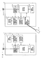
- FIG. 1 is a block diagram showing an example structure of the image display system according to the first embodiment.
- the image display system includes an image providing apparatus 1 and an image display apparatus 2.
- the infrared reception section 14 receives the control data and an identification code that are transmitted from the image display apparatus 2 by wireless communication using infrared light.
- FIG. 2 is a schematic diagram showing data transmitted from the image display apparatus 2 by infrared light.
- the data transmitted from the image display apparatus 2 by infrared light includes the control data and the identification code.
- the identification code is a code for identifying the image display apparatus 2 from which the control data has been transmitted and identifying other devices. That is, the identification code is a code used by the image display apparatus 2 to specify the image providing apparatus 1 as a transmission destination device. By the identification code, the image providing apparatus 1 can identify the control data as data transmitted from the image display apparatus 2.
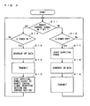
- step S11 When it is determined in step S11 that the remote control signal is the signal indicating a command to turn on power, the process proceeds to step S16.
- step S16 the control section 26 determines whether power to the image display apparatus 2 is on or off. When the control section 26 determines that power to the image display apparatus 2 is off, the process proceeds to step S17.
- step S17 the control section 26 controls the power section 25 to start supplying power to each element except for the remote control signal reception section 27 and the control section 26.
- step S18 the control section 26 generates on data indicating that power to the image display apparatus 2 is in an on state. Then, the control section 26 outputs the generated on data to the wireless communication section 23.
- FIG. 5 shows the case where the image providing apparatus 1 and the image display apparatus 2 are positioned such that the infrared reception section 14 is capable of receiving the control data.
- the control section 16 stops supplying power to the tuner section 11, the image/sound processing section 12, and the wireless communication section 13. The reason is that since the infrared reception section 14 is capable of receiving the control data, it is possible, by the infrared reception section 14, to operate in tandem with power to the image display apparatus 2.
- (b) of FIG. 5 shows the case where the image providing apparatus 1 and the image display apparatus 2 are positioned such that the infrared reception section 14 is incapable of receiving the control data.
- the control section 16 stops supplying power to the tuner section 11 and the image/sound processing section 12, but does not stop supplying power to the wireless communication section 13. The reason is that since the infrared reception section 14 is incapable of receiving the control data, it is necessary, by the wireless communication section 13, to operate in tandem with power to the image display apparatus 2.
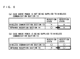
- FIG. 6 shows the change of the reception state of the infrared reception section 14 in the case where power to the image providing apparatus 1 is off in the state where power is being supplied to the wireless communication section 13.
- that power is being supplied to the wireless communication section 13 indicates that the infrared reception section 14 was incapable of receiving the control data when power to the image providing apparatus 1 was turned off.
- the heavy-lined box of (b) of FIG. 6 there may be a case where the installation position of either the image providing apparatus 1 or the image display apparatus 2 changes thereafter and the infrared reception section 14 becomes capable of receiving the control data.
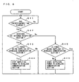
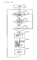
- step S31 determines whether power to the image display apparatus 2 is on or off (step S32).
- step S32 determines whether power to the image display apparatus 2 is on or off (step S32).
- step S33 determines whether power to the image display apparatus 2 is in an off state (step S33).
- the control section 26 controls the power section 25 to start supplying power to the infrared transmission section 24 (step S34).
Landscapes
- Engineering & Computer Science (AREA)
- Multimedia (AREA)
- Signal Processing (AREA)
- Computer Networks & Wireless Communication (AREA)
- General Engineering & Computer Science (AREA)
- Software Systems (AREA)
- Controls And Circuits For Display Device (AREA)
- Two-Way Televisions, Distribution Of Moving Picture Or The Like (AREA)
- Television Receiver Circuits (AREA)
- Details Of Television Systems (AREA)
Abstract
Claims (9)
- Système d'affichage d'image comprenant un appareil de fourniture d'image (1) destiné à fournir des données d'image par le biais d'une communication sans fil en utilisant des ondes radio et un appareil d'affichage d'image (2) destiné à afficher une image correspondant aux données d'image fournies par l'appareil de fourniture d'image (1),
l'appareil d'affichage d'image (2) comportant :une section (23) de communication sans fil côté affichage pour recevoir des données d'image fournies par l'appareil de fourniture d'image (1) ;une section (21) d'affichage pour afficher une image correspondant aux données d'image reçues par la section (23) de communication sans fil côté affichage ;une section (26) de commande côté affichage pour générer des données prédéterminées de mise hors tension lorsqu'on émet une instruction de mise hors tension de l'appareil d'affichage d'image (2); etune section (24) de transmission infrarouge côté affichage pour transmettre les données de mise hors tension à l'appareil de fourniture d'image (1) par le biais d'une communication sans fil en utilisant une lumière infrarouge,l'appareil de fourniture d'image (1) comportant :une section (11, 12) d'acquisition de données pour acquérir les données d'image à fournir à la section (23) de communication sans fil côté affichage ;une section (13) de communication sans fil côté fourniture pour fournir les données d'image acquises par la section (11, 12) d'acquisition de données à la section (23) de communication sans fil côté affichage ;une section (14) de réception infrarouge côté fourniture pour recevoir les données de mise hors tension transmises de la section (24) de transmission infrarouge côté affichage ; etune section (16) de commande côté fourniture,caractérisé en ce que le système est adapté de façon à ce que,lorsqu'on émet une instruction de mise hors tension de l'appareil d'affichage d'image (2), la section (24) de transmission infrarouge côté affichage transmette les données de mise hors tension à la section (14) de réception infrarouge côté fourniture par le biais d'une communication sans fil en utilisant une lumière infrarouge etla section (23) de communication sans fil côté affichage transmette les données de mise hors tension à la section (13) de communication sans fil côté fourniture par le biais d'une communication sans fil en utilisant des ondes radio etla section (16) de commande côté fourniture cesse l'alimentation électrique de la section (11, 12) d'acquisition de données et de la section (13) de communication sans fil côté fourniture lorsque les données de mise hors tension ont été reçues par la section (14) de réception infrarouge côté fourniture etla section (16) de commande côté fourniture cesse l'alimentation électrique uniquement de la section (11, 12) d'acquisition de données lorsque les données de mise hors tension n'ont pas été reçues par la section (14) de réception infrarouge côté fourniture et ont été reçues uniquement par la section (13) de communication sans fil côté fourniture. - Système d'affichage d'image selon la revendication 1,
dans lequel la section (24) de transmission infrarouge côté affichage transmet les données de mise hors tension à la section (14) de réception infrarouge côté fourniture à des intervalles de temps prédéterminés, et
dans lequel la section (16) de commande côté fourniture cesse l'alimentation électrique également de la section (13) de communication sans fil côté fourniture lorsque les données de mise hors tension ont été reçues par la section (14) de réception infrarouge côté fourniture aux intervalles de temps prédéterminés dans le cas où l'alimentation électrique uniquement de la section (11, 12) d'acquisition de données est coupée. - Système d'affichage d'image selon la revendication 1,
dans lequel la section (24) de transmission infrarouge côté affichage transmet les données de mise hors tension à la section (14) de réception infrarouge côté fourniture à des intervalles de temps prédéterminés, et
dans lequel la section (16) de commande côté fourniture commence l'alimentation électrique de la section (13) de communication sans fil côté fourniture lorsque les données de mise hors tension n'ont pas été reçues par la section (14) de réception infrarouge côté fourniture aux intervalles de temps prédéterminés dans le cas où l'alimentation électrique de la section (11, 12) d'acquisition de données et de la section (13) de communication sans fil côté fourniture est coupée. - Système d'affichage d'image selon la revendication 1,
dans lequel l'appareil de fourniture d'image (1) comporte en outre une section (18) de transmission infrarouge côté fourniture pour, dans le cas où l'alimentation électrique uniquement de la section (11, 12) d'acquisition de données est coupée, transmettre, par le biais d'une communication sans fil en utilisant une lumière infrarouge, des données indiquant une demande qui consiste à savoir si l'alimentation de l'appareil d'affichage d'image (2) est coupée ou non,
dans lequel l'appareil d'affichage d'image (2) comporte en outre une section (28) de réception infrarouge côté affichage pour recevoir les données indiquant une demande qui est transmise de la section (18) de transmission infrarouge côté fourniture,
dans lequel la section (24) de transmission infrarouge côté affichage transmet les données de mise hors tension à la section (14) de réception infrarouge côté fourniture lorsque les données indiquant une demande ont été reçues par la section (28) de réception infrarouge côté affichage, et
dans lequel la section (16) de commande côté fourniture cesse l'alimentation électrique également à la section (13) de communication sans fil côté fourniture lorsque les données de mise hors tension ont été reçues par la section (14) de réception infrarouge côté fourniture. - Système d'affichage d'image selon la revendication 1,
dans lequel l'appareil de fourniture d'image (1) comporte en outre une section (18) de transmission infrarouge côté fourniture pour, dans le cas où l'alimentation électrique de la section (11, 12) d'acquisition de données et de la section (13) de communication sans fil côté fourniture est coupée, transmettre, par le biais d'une communication sans fil en utilisant une lumière infrarouge, des données indiquant une demande qui consiste à savoir si l'alimentation de l'appareil d'affichage d'image (2) est coupée ou non,
dans lequel le dispositif d'affichage d'image (2) comporte en outre une section (28) de réception infrarouge côté affichage pour recevoir les données indiquant une demande qui est transmise de la section (18) de transmission infrarouge côté fourniture,
dans lequel la section (24) de transmission infrarouge côté affichage transmet les données de mise hors tension à la section (14) de réception infrarouge côté fourniture lorsque les données indiquant une demande ont été reçues par la section (28) de réception infrarouge côté affichage, et
dans lequel la section (16) de commande côté fourniture commence l'alimentation électrique de la section (13) de communication sans fil côté fourniture lorsque les données de mise hors tension n'ont pas été reçues par la section (14) de réception infrarouge côté fourniture. - Système d'affichage d'image selon la revendication 1,
dans lequel la section (26) de commande côté affichage génère des données prédéterminées de mise sous tension lorsqu'on émet une instruction de mise sous tension de l'appareil d'affichage d'image (2),
dans lequel la section (23) de communication sans fil côté affichage transmet les données de mise sous tension à la section (13) de communication sans fil côté fourniture par le biais d'une communication sans fil en utilisant des ondes radio,
dans lequel la section (24) de transmission infrarouge côté affichage transmet les données de mise sous tension à la section (14) de réception infrarouge côté fourniture par le biais d'une communication sans fil en utilisant une lumière infrarouge, et
dans lequel la section (16) de commande côté fourniture commence l'alimentation électrique de la section d'acquisition de données (11, 12) et de la section (13) de communication sans fil côté fourniture lorsque les données de mise sous tension ont été reçues par la section (14) de réception infrarouge côté fourniture, ou commence l'alimentation électrique de la section d'acquisition de données (11, 12) lorsque les données de mise sous tension n'ont pas été reçues par la section (14) de réception infrarouge côté fourniture et ont été reçues uniquement par la section (13) de communication sans fil côté fourniture. - Système d'affichage d'image selon la revendication 1,
dans lequel la section (26) de commande côté affichage génère des données prédéterminées de mise sous tension lorsqu'on émet une instruction de mise sous tension de l'appareil d'affichage d'image (2),
dans lequel la section (24) de transmission infrarouge côté affichage transmet les données de mise sous tension à la section (14) de réception infrarouge côté fourniture par le biais d'une communication sans fil en utilisant une lumière infrarouge, et
dans lequel la section (16) de commande côté fourniture commence l'alimentation électrique de la section d'acquisition de données (11, 12) et de la section (13) de communication sans fil côté fourniture lorsque les données de mise sous tension ont été reçues par la section (14) de réception infrarouge côté fourniture. - Appareil de fourniture d'image (1) destiné à fournir des données d'image à un appareil d'affichage d'image (2) par le biais d'une communication sans fil en utilisant des ondes radio, l'appareil de fourniture d'image (1) comprenant :une section d'acquisition de données (11, 12) pour acquérir des données d'image à fournir à l'appareil d'affichage d'image (2) ;une section (13) de communication sans fil côté fourniture pour fournir les données d'image acquises par la section d'acquisition de données (11, 12) à l'appareil d'affichage d'image (2) ; une section (14) de réception infrarouge côté fourniture pour recevoir des données prédéterminées de mise hors tension transmises de l'appareil d'affichage d'image (2) par le biais d'une communication sans fil en utilisant une lumière infrarouge lorsqu'on émet une instruction de mise hors tension de l'appareil d'affichage d'image (2) ;caractérisé en ce que l'appareil est adapté de façon à ce que,lorsqu'on émet une instruction de mise hors tension de l'appareil d'affichage d'image (2), l'appareil d'affichage d'image (2) transmette les données de mise hors tension à la section (13) de communication sans fil côté fourniture par le biais d'une communication sans fil en utilisant des ondes radio etl'appareil d'affichage d'image (2) transmette les données de mise hors tension à la section (14) de réception infrarouge côté fourniture par le biais d'une communication sans fil en utilisant une lumière infrarouge etla section (16) de commande côté fourniture cesse l'alimentation électrique de la section (11, 12) d'acquisition de données et de la section (13) de communication sans fil côté fourniture lorsque les données de mise hors tension ont été reçues par la section (14) de réception infrarouge côté fourniture, etla section (16) de commande côté fourniture cesse l'alimentation électrique uniquement de la section d'acquisition de données (11, 12) lorsque les données de mise hors tension n'ont pas été reçues par la section (14) de réception infrarouge côté fourniture et ont été reçues uniquement par la section (13) de communication sans fil côté fourniture.
- Système d'affichage d'image (2) destiné à afficher une image correspondant à des données d'image fournies par un appareil de fourniture d'image (1) par le biais d'une communication sans fil en utilisant des ondes radio, l'appareil d'affichage d'image (2) comprenant :une section (23) de communication sans fil côté affichage pour recevoir des données d'image fournies par l'appareil de fourniture d'image (1) ;une section d'affichage (21) pour afficher une image correspondant aux données d'image reçues par la section (23) de communication sans fil côté affichage;une section (26) de commande côté affichage pour, lorsqu'on émet une instruction de mise hors tension de l'appareil d'affichage d'image (2), générer des données de mise hors tension utilisées pour couper l'alimentation électrique à une section d'acquisition de données (11, 12) de l'appareil de fourniture d'image (1) afin d'acquérir les données d'image à fournir à la section (23) de communication sans fil côté affichage et à une section (13) de communication sans fil côté fourniture de l'appareil de fourniture d'image (1) afin de fournir les données d'image acquises par la section d'acquisition de données (11, 12) à la section (23) de communication sans fil côté affichage ; etla section (24) de transmission infrarouge côté affichage pour transmettre les données de mise hors tension à l'appareil de fourniture d'image (1) par le biais d'une communication sans fil en utilisant une lumière infrarouge,caractérisé en ce que l'appareil est adapté de façon à ce que,lorsqu'on émet une instruction de mise hors tension de l'appareil d'affichage d'image (2), la section (23) de communication sans fil côté affichage transmette les données de mise hors tension à la section (13) de communication sans fil côté fourniture par le biais d'une communication sans fil en utilisant des ondes radio etla section (24) de transmission infrarouge côté affichage transmette les données de mise hors tension à l'appareil de fourniture d'image (1) par le biais d'une communication sans fil en utilisant une lumière infrarouge etl'appareil de fourniture d'image (1) cesse l'alimentation électrique de la section d'acquisition de données (11, 12) et à sa section de communication sans fil lorsque les données de mise hors tension ont été reçues de la section (24) de transmission infrarouge côté affichage etl'appareil de fourniture d'image (1) cesse l'alimentation électrique uniquement de la section d'acquisition de données (11, 12) lorsque les données de mise hors tension n'ont pas été reçues de la section (24) de transmission infrarouge côté affichage et ont été reçues uniquement de la section (23) de communication sans fil côté affichage.
Applications Claiming Priority (2)
| Application Number | Priority Date | Filing Date | Title |
|---|---|---|---|
| JP2006098782A JP4873978B2 (ja) | 2006-03-31 | 2006-03-31 | 映像供給装置、映像表示装置、およびこれらで構成された映像表示システム |
| PCT/JP2007/054175 WO2007113966A1 (fr) | 2006-03-31 | 2007-03-05 | Appareils de fourniture et d'affichage d'image et systeme d'affichage d'image constitue par ceux-ci |
Publications (4)
| Publication Number | Publication Date |
|---|---|
| EP2003874A2 EP2003874A2 (fr) | 2008-12-17 |
| EP2003874A9 EP2003874A9 (fr) | 2009-04-15 |
| EP2003874A4 EP2003874A4 (fr) | 2009-06-03 |
| EP2003874B1 true EP2003874B1 (fr) | 2010-12-29 |
Family
ID=38563238
Family Applications (1)
| Application Number | Title | Priority Date | Filing Date |
|---|---|---|---|
| EP07715202A Expired - Fee Related EP2003874B1 (fr) | 2006-03-31 | 2007-03-05 | Appareils de fourniture et d'affichage d'image et systeme d'affichage d'image constitue par ceux-ci |
Country Status (6)
| Country | Link |
|---|---|
| US (1) | US20090115768A1 (fr) |
| EP (1) | EP2003874B1 (fr) |
| JP (1) | JP4873978B2 (fr) |
| CN (1) | CN101411177B (fr) |
| DE (1) | DE602007011586D1 (fr) |
| WO (1) | WO2007113966A1 (fr) |
Families Citing this family (8)
| Publication number | Priority date | Publication date | Assignee | Title |
|---|---|---|---|---|
| KR20090112101A (ko) * | 2008-04-23 | 2009-10-28 | 삼성전자주식회사 | 방송수신장치와 무선 인터페이스 장치 및 그 제어방법 |
| JP4626701B2 (ja) * | 2008-10-21 | 2011-02-09 | ソニー株式会社 | 表示装置 |
| KR20100045737A (ko) * | 2008-10-24 | 2010-05-04 | 삼성전자주식회사 | 디스플레이 장치 및 그 제어 방법 |
| JP2010263459A (ja) * | 2009-05-08 | 2010-11-18 | Sanyo Electric Co Ltd | 再生装置 |
| JP5373148B2 (ja) * | 2012-04-23 | 2013-12-18 | シャープ株式会社 | 表示装置、表示システム、表示装置の制御方法、プログラムおよび記録媒体 |
| JP5996975B2 (ja) * | 2012-09-05 | 2016-09-21 | Dxアンテナ株式会社 | 無線伝送システム |
| JP5996976B2 (ja) * | 2012-09-06 | 2016-09-21 | Dxアンテナ株式会社 | 無線伝送システム |
| KR20140091356A (ko) * | 2013-01-11 | 2014-07-21 | 삼성전자주식회사 | 디스플레이장치, 단말기 및 디스플레이장치의 영상제공방법 |
Family Cites Families (21)
| Publication number | Priority date | Publication date | Assignee | Title |
|---|---|---|---|---|
| US5383044B1 (en) * | 1992-09-18 | 1998-09-01 | Recoton Corp | Systems methods and apparatus for transmitting radio frequency remote control signals |
| US5475835A (en) * | 1993-03-02 | 1995-12-12 | Research Design & Marketing Inc. | Audio-visual inventory and play-back control system |
| US5625882A (en) * | 1994-03-01 | 1997-04-29 | Motorola, Inc. | Power management technique for determining a device mode of operation |
| WO1996031021A1 (fr) * | 1995-03-29 | 1996-10-03 | Norand Corporation | Reseau principal de communication a infra-rouge comportant une voie de secours en radio-frequence |
| US5880721A (en) * | 1997-07-14 | 1999-03-09 | Yen; Kerl | Radio computer audio-video transmission device |
| JP2001078168A (ja) * | 1999-09-08 | 2001-03-23 | Sony Corp | 表示装置、信号送受信装置、無線伝送装置及び信号送受信方法 |
| IL132711A (en) * | 1999-11-03 | 2005-05-17 | Elpas Electro Optic Systems Lt | Dual rf/ir communication device and method of use thereof |
| US6462437B1 (en) * | 1999-11-12 | 2002-10-08 | Koninklijke Philips Electronics N.V. | System and method for alternating standby mode |
| JP4449141B2 (ja) * | 2000-02-22 | 2010-04-14 | ソニー株式会社 | 電源制御装置、電源制御システム |
| US7865922B2 (en) * | 2000-10-03 | 2011-01-04 | Sony Corporation | Low-power broadcast receiver |
| JP2002247479A (ja) * | 2001-02-15 | 2002-08-30 | Sharp Corp | ビデオ無線送受信システム |
| JP2002247667A (ja) * | 2001-02-16 | 2002-08-30 | Hiroyuki Machida | 光リモコン中継装置 |
| WO2003092265A1 (fr) * | 2002-04-23 | 2003-11-06 | Sharp Kabushiki Kaisha | Systeme de gestion de commande de dispositif |
| US6975364B2 (en) * | 2002-06-13 | 2005-12-13 | Hui-Lin Lin | Radio television and frequency modulation monitor transmitting receiving control apparatus |
| JP3780982B2 (ja) * | 2002-07-05 | 2006-05-31 | ソニー株式会社 | 映像表示システム、映像表示方法及び表示装置 |
| CN100481786C (zh) * | 2002-08-09 | 2009-04-22 | 爱信艾达株式会社 | 通信装置电源管理系统 |
| JP2005223443A (ja) * | 2004-02-03 | 2005-08-18 | Jiyaruko:Kk | 高速無線データ通信機における待機電力の削減システム |
| JP2005303678A (ja) * | 2004-04-12 | 2005-10-27 | Sony Corp | 通信システム,送受信装置,受像システム,通信方法 |
| JP4335090B2 (ja) * | 2004-05-14 | 2009-09-30 | シャープ株式会社 | 移動端末装置 |
| KR100640891B1 (ko) * | 2004-09-02 | 2006-11-02 | 엘지전자 주식회사 | 무선 tv 파워 on/off 장치 및 방법 |
| WO2007040080A1 (fr) * | 2005-09-30 | 2007-04-12 | Matsushita Electric Industrial Co., Ltd. | Dispositif d’affichage vidéo et dispositif de reproduction |
-
2006
- 2006-03-31 JP JP2006098782A patent/JP4873978B2/ja not_active Expired - Fee Related
-
2007
- 2007-03-05 CN CN2007800109905A patent/CN101411177B/zh not_active Expired - Fee Related
- 2007-03-05 EP EP07715202A patent/EP2003874B1/fr not_active Expired - Fee Related
- 2007-03-05 DE DE602007011586T patent/DE602007011586D1/de active Active
- 2007-03-05 US US12/295,153 patent/US20090115768A1/en not_active Abandoned
- 2007-03-05 WO PCT/JP2007/054175 patent/WO2007113966A1/fr active Application Filing
Also Published As
| Publication number | Publication date |
|---|---|
| JP2007274440A (ja) | 2007-10-18 |
| US20090115768A1 (en) | 2009-05-07 |
| EP2003874A9 (fr) | 2009-04-15 |
| JP4873978B2 (ja) | 2012-02-08 |
| DE602007011586D1 (de) | 2011-02-10 |
| CN101411177A (zh) | 2009-04-15 |
| CN101411177B (zh) | 2012-02-22 |
| EP2003874A2 (fr) | 2008-12-17 |
| WO2007113966A1 (fr) | 2007-10-11 |
| EP2003874A4 (fr) | 2009-06-03 |
Similar Documents
| Publication | Publication Date | Title |
|---|---|---|
| EP2003874B1 (fr) | Appareils de fourniture et d'affichage d'image et systeme d'affichage d'image constitue par ceux-ci | |
| EP1587253B1 (fr) | Système de communication pour l'échange de donnèes multimédia entre une unité parent et une unité enfant | |
| US7221410B2 (en) | Television receiving module and display apparatus and television receiving system using the same | |
| US6795130B2 (en) | Signal receiving apparatus, remote controller, signal receiving system, and apparatus to be controlled | |
| JP2010206441A (ja) | テレビジョン受信装置 | |
| US7679688B2 (en) | Wireless TV system and control method thereof | |
| KR20070052075A (ko) | 양방향 케이블 디지털 방송의 비상 사태 경보 메시지 처리방법, 데이터 구조 및 이를 위한 방송 수신기 | |
| JP4212415B2 (ja) | 放送受信システム | |
| US6798459B1 (en) | Apparatus and method for transmitting and receiving, as an electric wave, a signal generated by electronic equipment, and a control signal to control operation of the electronic equipment | |
| KR20090020897A (ko) | 외부기기의 제어명령에 따라 제어되는 무선 영상시스템,무선 영상수신기 및 무선 영상시스템 제어방법 | |
| US20090066855A1 (en) | Television broadcast receiving system | |
| EP1653736A1 (fr) | Dispositif et procede de commande d'economie de courant | |
| EP2160023B1 (fr) | Appareil de réception de diffusion capable de communiquer avec un appareil externe et procédé d'utilisation du contenu | |
| US20120030697A1 (en) | Display control aparatus, display control method, program, and recording medium | |
| US7934246B2 (en) | Broadcast receiver | |
| EP3790279B1 (fr) | Dispositif d'affichage d'images, procédé de connexion de dispositif périphérique et système d'affichage d'images incluant un tel dispositif d'affichage d'images | |
| JP2005229495A (ja) | 浴室テレビ等の制御装置 | |
| KR101163773B1 (ko) | 소비 전력 감소 tv | |
| KR101194318B1 (ko) | 자동 채널 설정 제어방법 및 이를 적용한 영상 표시장치 | |
| US20100293582A1 (en) | Reproducing apparatus | |
| JP2011109328A (ja) | 放送受信装置及びその制御方法 | |
| JP5996976B2 (ja) | 無線伝送システム | |
| JP2002247479A (ja) | ビデオ無線送受信システム | |
| JP2002271703A (ja) | ビデオ無線送受信システム | |
| JP2002252818A (ja) | ビデオ無線送受信システム |
Legal Events
| Date | Code | Title | Description |
|---|---|---|---|
| PUAI | Public reference made under article 153(3) epc to a published international application that has entered the european phase |
Free format text: ORIGINAL CODE: 0009012 |
|
| 17P | Request for examination filed |
Effective date: 20081001 |
|
| AK | Designated contracting states |
Kind code of ref document: A2 Designated state(s): DE FR GB |
|
| PUAB | Information related to the publication of an a document modified or deleted |
Free format text: ORIGINAL CODE: 0009199EPPU |
|
| A4 | Supplementary search report drawn up and despatched |
Effective date: 20090506 |
|
| DAX | Request for extension of the european patent (deleted) | ||
| RBV | Designated contracting states (corrected) |
Designated state(s): DE FR GB |
|
| 17Q | First examination report despatched |
Effective date: 20100219 |
|
| GRAP | Despatch of communication of intention to grant a patent |
Free format text: ORIGINAL CODE: EPIDOSNIGR1 |
|
| GRAS | Grant fee paid |
Free format text: ORIGINAL CODE: EPIDOSNIGR3 |
|
| GRAA | (expected) grant |
Free format text: ORIGINAL CODE: 0009210 |
|
| AK | Designated contracting states |
Kind code of ref document: B1 Designated state(s): DE FR GB |
|
| REG | Reference to a national code |
Ref country code: GB Ref legal event code: FG4D |
|
| REF | Corresponds to: |
Ref document number: 602007011586 Country of ref document: DE Date of ref document: 20110210 Kind code of ref document: P |
|
| REG | Reference to a national code |
Ref country code: DE Ref legal event code: R096 Ref document number: 602007011586 Country of ref document: DE Effective date: 20110210 |
|
| PLBE | No opposition filed within time limit |
Free format text: ORIGINAL CODE: 0009261 |
|
| STAA | Information on the status of an ep patent application or granted ep patent |
Free format text: STATUS: NO OPPOSITION FILED WITHIN TIME LIMIT |
|
| 26N | No opposition filed |
Effective date: 20110930 |
|
| REG | Reference to a national code |
Ref country code: DE Ref legal event code: R097 Ref document number: 602007011586 Country of ref document: DE Effective date: 20110930 |
|
| REG | Reference to a national code |
Ref country code: FR Ref legal event code: PLFP Year of fee payment: 9 |
|
| PGFP | Annual fee paid to national office [announced via postgrant information from national office to epo] |
Ref country code: DE Payment date: 20150224 Year of fee payment: 9 |
|
| PGFP | Annual fee paid to national office [announced via postgrant information from national office to epo] |
Ref country code: GB Payment date: 20150304 Year of fee payment: 9 Ref country code: FR Payment date: 20150309 Year of fee payment: 9 |
|
| REG | Reference to a national code |
Ref country code: DE Ref legal event code: R119 Ref document number: 602007011586 Country of ref document: DE |
|
| GBPC | Gb: european patent ceased through non-payment of renewal fee |
Effective date: 20160305 |
|
| REG | Reference to a national code |
Ref country code: FR Ref legal event code: ST Effective date: 20161130 |
|
| PG25 | Lapsed in a contracting state [announced via postgrant information from national office to epo] |
Ref country code: GB Free format text: LAPSE BECAUSE OF NON-PAYMENT OF DUE FEES Effective date: 20160305 Ref country code: DE Free format text: LAPSE BECAUSE OF NON-PAYMENT OF DUE FEES Effective date: 20161001 Ref country code: FR Free format text: LAPSE BECAUSE OF NON-PAYMENT OF DUE FEES Effective date: 20160331 |