EP2003326B1 - Kraftstoffinjektor mit Linearantrieb - Google Patents
Kraftstoffinjektor mit Linearantrieb Download PDFInfo
- Publication number
- EP2003326B1 EP2003326B1 EP08104105A EP08104105A EP2003326B1 EP 2003326 B1 EP2003326 B1 EP 2003326B1 EP 08104105 A EP08104105 A EP 08104105A EP 08104105 A EP08104105 A EP 08104105A EP 2003326 B1 EP2003326 B1 EP 2003326B1
- Authority
- EP
- European Patent Office
- Prior art keywords
- coil
- fuel injector
- valve
- active element
- permanent magnet
- Prior art date
- Legal status (The legal status is an assumption and is not a legal conclusion. Google has not performed a legal analysis and makes no representation as to the accuracy of the status listed.)
- Not-in-force
Links
- 239000000446 fuel Substances 0.000 title claims description 65
- 230000005291 magnetic effect Effects 0.000 abstract description 35
- 238000002347 injection Methods 0.000 description 20
- 239000007924 injection Substances 0.000 description 20
- 238000002485 combustion reaction Methods 0.000 description 12
- 230000004907 flux Effects 0.000 description 6
- 239000000243 solution Substances 0.000 description 6
- XEEYBQQBJWHFJM-UHFFFAOYSA-N Iron Chemical compound [Fe] XEEYBQQBJWHFJM-UHFFFAOYSA-N 0.000 description 4
- 230000005540 biological transmission Effects 0.000 description 4
- 238000010586 diagram Methods 0.000 description 3
- 230000015556 catabolic process Effects 0.000 description 2
- 238000006731 degradation reaction Methods 0.000 description 2
- 230000005284 excitation Effects 0.000 description 2
- 229910052742 iron Inorganic materials 0.000 description 2
- 230000035699 permeability Effects 0.000 description 2
- 230000008901 benefit Effects 0.000 description 1
- 230000006835 compression Effects 0.000 description 1
- 238000007906 compression Methods 0.000 description 1
- 230000001419 dependent effect Effects 0.000 description 1
- 230000005611 electricity Effects 0.000 description 1
- 239000004744 fabric Substances 0.000 description 1
- 238000007654 immersion Methods 0.000 description 1
- 238000009434 installation Methods 0.000 description 1
- 230000005923 long-lasting effect Effects 0.000 description 1
- 238000000034 method Methods 0.000 description 1
- 230000008569 process Effects 0.000 description 1
- 230000004044 response Effects 0.000 description 1
- 230000002441 reversible effect Effects 0.000 description 1
- 238000007789 sealing Methods 0.000 description 1
- 238000006467 substitution reaction Methods 0.000 description 1
- 238000004804 winding Methods 0.000 description 1
Images



Classifications
-
- F—MECHANICAL ENGINEERING; LIGHTING; HEATING; WEAPONS; BLASTING
- F02—COMBUSTION ENGINES; HOT-GAS OR COMBUSTION-PRODUCT ENGINE PLANTS
- F02M—SUPPLYING COMBUSTION ENGINES IN GENERAL WITH COMBUSTIBLE MIXTURES OR CONSTITUENTS THEREOF
- F02M47/00—Fuel-injection apparatus operated cyclically with fuel-injection valves actuated by fluid pressure
- F02M47/02—Fuel-injection apparatus operated cyclically with fuel-injection valves actuated by fluid pressure of accumulator-injector type, i.e. having fuel pressure of accumulator tending to open, and fuel pressure in other chamber tending to close, injection valves and having means for periodically releasing that closing pressure
- F02M47/027—Electrically actuated valves draining the chamber to release the closing pressure
-
- F—MECHANICAL ENGINEERING; LIGHTING; HEATING; WEAPONS; BLASTING
- F02—COMBUSTION ENGINES; HOT-GAS OR COMBUSTION-PRODUCT ENGINE PLANTS
- F02M—SUPPLYING COMBUSTION ENGINES IN GENERAL WITH COMBUSTIBLE MIXTURES OR CONSTITUENTS THEREOF
- F02M63/00—Other fuel-injection apparatus having pertinent characteristics not provided for in groups F02M39/00 - F02M57/00 or F02M67/00; Details, component parts, or accessories of fuel-injection apparatus, not provided for in, or of interest apart from, the apparatus of groups F02M39/00 - F02M61/00 or F02M67/00; Combination of fuel pump with other devices, e.g. lubricating oil pump
- F02M63/0012—Valves
- F02M63/0014—Valves characterised by the valve actuating means
- F02M63/0015—Valves characterised by the valve actuating means electrical, e.g. using solenoid
-
- F—MECHANICAL ENGINEERING; LIGHTING; HEATING; WEAPONS; BLASTING
- F02—COMBUSTION ENGINES; HOT-GAS OR COMBUSTION-PRODUCT ENGINE PLANTS
- F02M—SUPPLYING COMBUSTION ENGINES IN GENERAL WITH COMBUSTIBLE MIXTURES OR CONSTITUENTS THEREOF
- F02M63/00—Other fuel-injection apparatus having pertinent characteristics not provided for in groups F02M39/00 - F02M57/00 or F02M67/00; Details, component parts, or accessories of fuel-injection apparatus, not provided for in, or of interest apart from, the apparatus of groups F02M39/00 - F02M61/00 or F02M67/00; Combination of fuel pump with other devices, e.g. lubricating oil pump
- F02M63/0012—Valves
- F02M63/0014—Valves characterised by the valve actuating means
- F02M63/0015—Valves characterised by the valve actuating means electrical, e.g. using solenoid
- F02M63/0024—Valves characterised by the valve actuating means electrical, e.g. using solenoid in combination with permanent magnet
-
- F—MECHANICAL ENGINEERING; LIGHTING; HEATING; WEAPONS; BLASTING
- F02—COMBUSTION ENGINES; HOT-GAS OR COMBUSTION-PRODUCT ENGINE PLANTS
- F02M—SUPPLYING COMBUSTION ENGINES IN GENERAL WITH COMBUSTIBLE MIXTURES OR CONSTITUENTS THEREOF
- F02M63/00—Other fuel-injection apparatus having pertinent characteristics not provided for in groups F02M39/00 - F02M57/00 or F02M67/00; Details, component parts, or accessories of fuel-injection apparatus, not provided for in, or of interest apart from, the apparatus of groups F02M39/00 - F02M61/00 or F02M67/00; Combination of fuel pump with other devices, e.g. lubricating oil pump
- F02M63/0012—Valves
- F02M63/007—Details not provided for in, or of interest apart from, the apparatus of the groups F02M63/0014 - F02M63/0059
- F02M63/0078—Valve member details, e.g. special shape, hollow or fuel passages in the valve member
- F02M63/008—Hollow valve members, e.g. members internally guided
-
- F—MECHANICAL ENGINEERING; LIGHTING; HEATING; WEAPONS; BLASTING
- F02—COMBUSTION ENGINES; HOT-GAS OR COMBUSTION-PRODUCT ENGINE PLANTS
- F02M—SUPPLYING COMBUSTION ENGINES IN GENERAL WITH COMBUSTIBLE MIXTURES OR CONSTITUENTS THEREOF
- F02M2547/00—Special features for fuel-injection valves actuated by fluid pressure
- F02M2547/003—Valve inserts containing control chamber and valve piston
-
- F—MECHANICAL ENGINEERING; LIGHTING; HEATING; WEAPONS; BLASTING
- F02—COMBUSTION ENGINES; HOT-GAS OR COMBUSTION-PRODUCT ENGINE PLANTS
- F02M—SUPPLYING COMBUSTION ENGINES IN GENERAL WITH COMBUSTIBLE MIXTURES OR CONSTITUENTS THEREOF
- F02M63/00—Other fuel-injection apparatus having pertinent characteristics not provided for in groups F02M39/00 - F02M57/00 or F02M67/00; Details, component parts, or accessories of fuel-injection apparatus, not provided for in, or of interest apart from, the apparatus of groups F02M39/00 - F02M61/00 or F02M67/00; Combination of fuel pump with other devices, e.g. lubricating oil pump
- F02M63/0012—Valves
- F02M63/0031—Valves characterized by the type of valves, e.g. special valve member details, valve seat details, valve housing details
- F02M63/0033—Lift valves, i.e. having a valve member that moves perpendicularly to the plane of the valve seat
- F02M63/0036—Lift valves, i.e. having a valve member that moves perpendicularly to the plane of the valve seat with spherical or partly spherical shaped valve member ends
Definitions
- the armature of the solenoid valve is designed as a two-part armature, so as to reduce the moving mass of the unit of armature and valve member and thus the bouncing kinetic energy.
- a valve element in the de-energized this means pressed in the inactive state of the solenoid valve via a preloaded compression spring against a stop. This stop is in most cases identical to the valve seat.
- the valve In the idle state of the solenoid valve, d. H. when solenoid valve of the solenoid valve is de-energized, the valve is closed, d. H. the anchor bolt with the closing element received thereon is pressed by a valve spring into the seat of the closing element. If the magnetic coil of the solenoid valve, however, energized, so there is a force that moves the closing element against the force of the closing spring from the seat. After the end of the current supply biased in the upward movement of the anchor bolt closing spring ensures that the closing element is returned to its original position. This is independent of whether a pressure-compensated or a pressure-dependent biased valve is actuated by means of the closing element.
- a high pressure control unit for a solenoid valve according to DE 196 50 865 A1 includes a magnet group, an armature group and a valve group.
- the present invention has for its object to provide a fuel injector having an improved response to opening and closing movements of the injection valve member.
- a fuel injector which has a linear drive which functions on the basis of the Lorentz force.
- the inventively proposed linear actuator operates as a plunger coil within a permanent magnet, similar to a speaker drive, and can act in two directions depending on the current direction.
- a permanent magnet can be used, an electromagnet can be used, on which there is an excitation coil, which can be operated parallel to the solenoid in series or separately from this.
- a permanent magnet instead of the solenoid valves previously used for fuel injectors for their actuation, a permanent magnet can be used which generates a permanent magnetic flux in the air gap.
- a plunger coil Within this air gap moves a plunger coil, which also generates a magnetic field in the energized state.
- the generated magnetic field is oriented such that a force is generated, which is opposite to a valve spring generated force is directed.
- the transmission of the force generated by the magnetic field via a valve spring receiving the spring.
- the force generated by the magnetic field for example, designed as a valve ball active element is moved and thus relieves a control chamber of the fuel injector via the outlet throttle, so that the invention proposed fuel injector injects a defined amount of fuel into the combustion chamber of the self-igniting internal combustion engine.
- the injection process is then completed as soon as the energization of the solenoid is canceled and consequently the control chamber is closed again by the active element moved into its seat, here for example embodied in spherical form, and a system pressure causing the closing of a needle-shaped injection valve member is established.
- a coil is wound on a coil carrier. This generated with a corresponding length of the coil wire and corresponding energization sufficient magnetic flux, such that sets a magnetic force that is greater than the force applied by the valve spring force.
- the bobbin is preferably fixedly connected to a valve spring receptacle, so that a power transmission can be realized.
- valve spring receptacle An alignment of the mentioned valve spring receptacle relative to the electromagnet and relative to the solenoid valve is achieved via a guide.
- the valve spring receptacle is performed with minimally trained game.
- the armature stroke is adjusted by a shim, which is installed between the body and the guide.
- the contacting of the magnetic coil is preferably carried out via flexible lines, which may be reinforced for example by a tissue.
- the electrical connection can also be realized via sliding contacts, as implemented, for example, at the commutator of electric motors.
- lines from the injector connector to the flexible line are integrated. The connection of the integrated line with the flexible line can be done for example via a plug contact.
- the magnetic head of the inventively proposed solenoid valve can be clamped by a magnetic clamping nut against the injector body of the fuel injector and at the same time presses the guide against the body of the fuel injector.
- the return takes place through the armature assembly of the solenoid valve and can be at different locations.
- holes in the valve spring receptacle on the bottom (valve spring pad) can be mounted or in the coil carrier cutouts are introduced in the area between the valve spring receptacle and solenoid coil.
- the proposed solution according to the invention is characterized in that compared to previously manufactured solenoid valves, a considerably smaller number of individual parts is required and the power loss, in particular the eddy currents, of the entire system is reduced. By a smaller electrical time constant and smaller moving masses, a highly dynamic drive for a fuel injector can be realized, whereby multiple pre and post injections can be realized. Furthermore, by the solution proposed according to the invention, a very slimline fuel injector can be realized in which a solenoid actuator can be used instead of a piezoactuator or a piezoelectric injector. Furthermore, an in-line solenoid valve can be represented by the solution proposed by the invention. The solution proposed according to the invention also has the advantage that a residual air gap setting can now be omitted.
- solenoid valve In contrast to previously used solenoid valves for actuating fuel injectors of the force vector is reversible according to the invention proposed solenoid valve.
- the linear actuator for fuel injectors proposed according to the invention can, on the one hand, be used to actuate fuel injectors, which are connected by way of e.g. On the other hand, it can also be used in future expected applications with a slide valve or pin valve variant.
- FIG. 1 The representation according to FIG. 1 is to be taken from a known from the prior art solenoid valve for actuating a fuel injector.
- FIG. 1 shows a fuel injector 10 in the region of its injector head 12 comprises a solenoid valve 14.
- the solenoid valve 14 includes a magnetic group of an armature group and a valve group.
- the magnet group includes a magnetic core 18, which has a passage opening in which a closing spring 16 is located. In the magnetic core 18, a magnetic coil 22 is inserted.
- Anchor bolt 32, an armature guide 30 and an armature plate 26 movably guided on the armature bolt include a plan side 28.
- the armature plate 26 displaceably guided on the armature bolt 32 is prestressed via an armature spring 50.
- the valve group includes a provided at the lower end of the anchor bolt 32 ball guide 34 which performs a trained as a valve ball 36 active element.
- the spherically shaped active element 36 closes a drainage channel with outlet throttle 42, via which a control chamber 40, which is formed in a valve piece 38, can be depressurized.
- a securing sleeve 20 is mounted, which encloses a recessed in a recess on the circumference of the anchor bolt 32 securing ring 24.
- closing spring 16 presses in the de-energized state of the solenoid valve 14 via the anchor bolt 32 on the example spherically formed active element 36.
- the solenoid valve 14 as shown in FIG. 1 however, energized, the solenoid 22 of the solenoid valve 14 attracts the armature plate 26, the fuel under high pressure (system pressure) can escape via the now opening outlet throttle 42 from the control chamber 40 in the valve member 38 in a low-pressure side return.
- system pressure system pressure
- By the pressure relief of the control chamber 40 is an injection valve member 46 - FIG. 1 only hinted at - by a pressure step, which in FIG. 1 is not shown, pressed in the opening direction.
- this injection openings are at the combustion chamber end of the fuel injector 10 free, so that fuel is injected into the combustion chamber, which lasts until the solenoid valve 14 goes back to the de-energized state.
- the outlet throttle 42 is closed again by the spherically shaped active element 36, so that builds up pressure on the plan side of the injection valve member 46 in the control chamber 40 of the fuel injector 10 and the injection valve member 46 is pressed back into its combustion chamber side seat.
- FIG. 1 illustrated high pressure hydraulic of a solenoid valve 14 makes use of the flat armature principle. This has proven itself because of its robustness and can also be used in currently ongoing development of subsequent generations of fuel injectors 10.
- the dynamics of a solenoid valve 14, among other parameters, are determined by the speed at which a magnetic field is built up in the iron.
- the resulting eddy currents delay the field and field degradation of the magnetic field in the iron.
- the magnet group comprises an electromagnet 52 having an M-shaped yoke.
- the middle leg of the yoke of the electromagnet 52 is wrapped by an excitation coil 54, whose terminals are identified by reference numeral 56.
- a coil support 62 Between the two outer legs of the M-shaped yoke of the electromagnet 52 is a coil support 62, on the outer circumference of a coil 58 is connected.
- the coil 58 has coil terminals indicated by reference numeral 60.
- the coil 58 acts as a plunger coil.
- the electromagnet 52 generates a magnetic flux in the air gap.
- the coil 58 moves as a plunger coil, which also generates a magnetic field in the energized state, which acts in the direction against the valve spring (see position 16 in FIG. 1 ) acts.
- FIG. 3 shows an embodiment with a permanent magnet 66, which is also designed M-shaped.
- the coil 58 which serves as a plunger coil, the direction of movement of the bobbin 62 is indicated by reference numeral 64.
- the directions of movement 64 in which the bobbin 62 moves with the coil 58 (plunger coil) accommodated thereon, are identified by the double arrow indicated by the reference numeral 64.
- the permanent magnet 66 comprises a part of a drainage channel designated by reference numeral 74, through which fuel discharged during the opening of a seat 76 from the control chamber 40 flows into the low-pressure region of the fuel injector 10.
- the permanent magnet 66 as shown in FIG. 4 is rotationally symmetrical and comprises an inner yoke, which is enclosed by a yoke designed as an outer ring.
- the coil 58 has an annular shape and is at a in the illustration according to FIG. 4 received sleeve-shaped coil carrier 62. At the lower end of the sleeve-shaped in this embodiment coil carrier 62 is provided with coil terminals 60 which are connected to connecting lines 82.
- the coil 58 which is defined between the inner pin-shaped yoke and the outer yoke formed as an outer yoke cavity acts as a plunger coil and can be moved depending on the energization, either in the vertical direction upwards or in the vertical direction downwards.
- the bobbin 62 as shown in FIG. 4 is connected to a sleeve-shaped valve spring receptacle 68.
- this can pull the coil support 62 and connected to this valve spring receptacle 68 in the vertical direction, so that in the illustration FIG. 4
- spherically shaped active element 36 is lifted from its indicated by reference numeral 76 seat.
- FIG. 4 illustrated embodiment shows that the example spherically formed active element 36 is received in a ball guide 34 at the lower end of the anchor bolt 62.
- a drain channel for pressure relief of the control chamber 40.
- the outlet throttle 42 is formed; the control chamber 40 is always acted upon by a designated by reference numeral 44 inlet throttle with fuel under system pressure.
- the valve piece 38 is sealed by a sealing ring 78.
- FIG. 4 further shows that the valve piece 38 is fixed in the injector body of the fuel injector 10 by the valve clamping nut 48.
- the valve spring receptacle 68 in which the closing spring 16 is received, is in turn enclosed by a guide 70.
- the guide 70 has at least one opening 72, via which controlled amount of the control chamber 40 of the fuel injector 10 in the permanent magnet 66 passing through and extending to the low pressure region of the fuel injector 10 drainage channel 74 can be controlled.
- the guide 70 is on the one hand by the lid of the Solenoid valve 14 and on the other hand enclosed by the injector body of the fuel injector 10 and fixed in Kraftstoffinj ector 10.
- the coil 58 (plunger coil) is wound, which generates a sufficient magnetic flux with appropriate wire length and energization, such that a force is generated which is greater than the closing force generated by the valve spring 16.
- the bobbin 62 is fixedly connected to the valve spring receptacle 68, so that a power transmission can take place at any time.
- valve spring receptacle 68 For an alignment of the valve spring receptacle 68 to the permanent magnet 66 and the solenoid valve 16 provides the guide 70. In this, the valve spring receptacle 68 is guided with minimal radial play.
- the armature stroke is set, for example, via a dial that is installed between the injector body and the guide 70.
- the contacting of the coil 58 takes place, for example, by flexible contacts 60, which may be reinforced by a fabric, for example.
- the electrical connection can also be replaced by sliding contacts, such as those used at the commutator of electric motors.
- lines from the injector connector to the flexible lines are integrated.
- the connection of the integrated connection line 82 to the flexible coil terminals 60 can be made, for example, via a plug contact or the like.
- FIG. 4 is an embodiment with permanent magnet 66 according to FIG. 3 indicated; instead of in FIG. 4 shown permanent magnet 66 but can also in FIG. 2 shown electromagnet 52 are used.
- FIG. 5 is a further embodiment of the present invention proposed linear actuator for actuating a fuel injector refer.
- the fuel injector 10 includes the injector head 12 within which a solenoid valve 14 is located.
- the solenoid valve 14 in turn comprises the permanent magnet 66, which comprises a substantially pin-shaped inner yoke, which is traversed by the flow channel 74. Forming a free space on the permanent magnet 66, a peg-shaped inner yoke enclosing outer yoke is formed. In the free space between the peg-shaped Inner yoke and the outer yoke is the bobbin 62, on the outer circumferential surface of the coil 58 is attached. The coil 58 or its coil terminals 60 are contacted on a disk-shaped plug 80, which in turn is electrically contacted via extending through the cover of the solenoid valve 14 connecting leads 82.
- the cover of the solenoid valve 14 is connected to the injector body of the fuel injector 10. Similar to the in FIG. 4 1, the sleeve-shaped coil carrier 62, which accommodates the coil 58 (plunger coil), is connected to a valve slide 84.
- the valve spool 84 corresponds approximately to the in FIG. 4
- the valve spring 16 is inserted into the valve spool 84 and is supported at its upper end on the pin-shaped, inner yoke of the permanent magnet 66, which is traversed by the outlet channel 74, from.
- FIG. 5 illustrated embodiment of erfindunshow proposed fuel injector 10, the valve member 38, which limits by control chamber 40.
- a pin boss 90 which merges into a bolt on which the valve spool 84 is guided inside.
- a collar is formed, which cooperates with one of the valve clamping nut 84 on an adjusting 88 fixed Ankerhubanschlag 86.
- the Ankerhubanschlag 86 is formed substantially annular and has an inner diameter which is smaller than the inner diameter of the adjusting ring 88, on which the Ankerhubanschlag 86 is supported.
- the inner diameter of the substantially disk-shaped Ankerhubanschlages 86 is in turn dimensioned so that a formed on the outer circumferential surface of the valve spool 84 collar strikes the Ankerhubanschlag 86.
- the valve spool 84 closes or opens a hydraulic space above the seat 76.
- the outlet throttle 42 opens to pressure relief of the control chamber 40.
- the control chamber 40 in turn is always acted upon by the inlet throttle 44 under standing at system pressure fuel. Depending on the pressure relief or pressurization of the control chamber 40 moves the substantially needle-shaped - in FIG.
- injection valve member 46 in a vertical upward direction and opens the injection port at the combustion chamber side end of the fuel injector 10 and down into the seat of the injection valve member 46, so that at least one formed at the combustion chamber end of the fuel injector 10 injection port is closed again.
- the permanent magnet 66 comprises a pin-shaped inner yoke 56, which is traversed by the flow channel 74 in the vertical direction.
- the drainage channel 74 may also be arranged extending outside of the magnetic core.
- the permanent magnet 66 is analogous to the representation according to FIG. 4 an annular outer yoke 98 is formed.
- the cavity 100 represents the space within which the coil 58 located on the outer circumferential surface of the bobbin 62 moves up or down in a vertical direction as a plunger coil.
- Reference numeral 102 denotes the injector body of the fuel injector 10.
- the shape of the coil 58 and the permanent magnet 66 is so flexible that an inline solenoid valve - as in FIG. 6 represented - can be created.
- the trained in a large height H permanent magnet 66 has a diameter D, which is smaller by a multiple than the height.
- the in FIG. 6 shown linear actuator can be accommodated in the injector body 102 of the fuel injector 10 and can serve, for example, as a substitution of the previously installed piezoelectric actuator. Due to the slimline geometry of the in FIG. 6 shown permanent magnet 66 results in a long-lasting bobbin 62, on the circumferential surface of which serving as a coil coil coil 58 is wound.
- the permanent magnet 66 comprises an inner yoke 96 and an outer yoke 58 surrounding it in an annular manner. Between the inner yoke 96 and the outer yoke 98 there is the cavity 100 in which the coil 58 accommodated on the coil carrier 62 is accommodated in a vertically movable manner. Also in the in FIG. 6 illustrated embodiment (inline solenoid valve), the bobbin 62 moves according to the double arrow 64 depending on the energization of the coil 58 in the vertical direction of movement up or down.
- the injector 102 of the in FIG. 6 represented fuel injector 10 is crossed by a high pressure line 92 and the outer yoke 98 of the permanent magnet 66 is supported on a support edge 94 which is formed in the injector body 102.
- linear drive is known over known from the prior art solenoid valves characterized in that it comprises a few items and the power loss of the solenoid valve is considerably lower than that of the solenoid valve 14, which in the fuel injector 10 according to FIG. 1 Application finds.
- inventively proposed linear drive according to the embodiments in the FIGS. 2 to 6 a smaller electrical time constant and smaller moving masses of the parts, so that a highly dynamic drive can be realized.
- an extremely slim-fitting solenoid valve can be realized, so that it can replace the relatively expensive piezoelectric actuator used to date on fuel injectors, since the installation spaces of the slimline solenoid valve as shown in FIG. 6 and the piezoelectric actuator are somewhat comparable so that an in-line solenoid valve implementation can be achieved. Furthermore, a complicated and time-consuming and, moreover, difficult to automate residual air gap adjustment is dispensable in the linear drive proposed according to the invention. In contrast to previously used magnets, the force vector can be reversed in the linear drive proposed according to the invention.
Landscapes
- Engineering & Computer Science (AREA)
- Chemical & Material Sciences (AREA)
- Combustion & Propulsion (AREA)
- Mechanical Engineering (AREA)
- General Engineering & Computer Science (AREA)
- Physics & Mathematics (AREA)
- Fluid Mechanics (AREA)
- Fuel-Injection Apparatus (AREA)
- Magnetically Actuated Valves (AREA)
Description
- Gemäß
DE 196 50 865 A1 undDE 197 08 104 A1 ist der Anker des Magnetventils als zweiteiliger Magnetanker ausgebildet, um so die bewegte Masse der Einheit aus Anker und Ventilglied und damit die das Prellen verursachende kinetische Energie zu verringern. - Bei den bekannten Magnetventilen wird ein Ventilelement im unbestromten, dies bedeutet im inaktiven Zustand des Magnetventils über eine vorgespannte Druckfeder gegen einen Anschlag gedrückt. Dieser Anschlag ist in den meisten Fällen identisch mit den Ventilsitz. Im Ruhezustand des Magnetventiles, d. h. bei unbestromter Magnetsspule des Magnetventiles ist das Ventil geschlossen, d. h. der Ankerbolzen mit daran aufgenommenem Schließelement wird durch eine Ventilfeder in den Sitz des Schließelementes gedrückt. Wird die Magnetspule des Magnetventiles hingegen bestromt, so entsteht eine Kraft, die das Schließelement gegen die Kraft der Schließfeder vom Sitz weg bewegt. Nach Ende der Bestromung sorgt die bei der Aufwärtsbewegung des Ankerbolzens vorgespannte Schließfeder dafür, dass das Schließelement wieder in seine Ausgangsposition gestellt wird. Dies ist unabhängig davon, ob mittels des Schließelementes ein druckausgeglichenes oder ein druckabhängig vorgespanntes Ventil betätigt wird.
- In Hochdruckspeichereinspritzsystemen, wie zum Beispiel Common-Rail-Speichereinspritzsystemen, für selbstzündende Verbrennungskraftmaschinen werden elektrisch gesteuerte Kraftstoffinjektoren zu präzisen Einspritzung des Kraftstoffs in den Brennraum der Verbrennungskraftmaschine eingesetzt. Diese Kraftstoffinjektoren umfassen verschiedene Ventile, die jeweils von einem Magneten angesteuert werden können. Wie alle magnetischen Steller umfasst eine Magnetbaugruppe eine Magnetspule, einen Magnetkern sowie einen Anker, sei er ein- oder mehrteilig aufgebaut. Eine Hochdrucksteuereinheit für ein Magnetventil gemäß
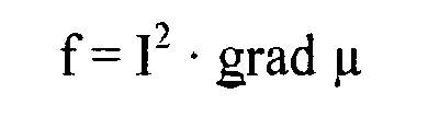
DE 196 50 865 A1 umfasst eine Magnetgruppe, eine Ankergruppe und eine Ventilgruppe. - Diese für Magnetventile typische Steuerung erfolgt in den bisherigen Generationen von Kraftstoffinjektoren nach dem Flachankerprinzip. Für künftig einzusetzende Generationen wird ein ebenfalls gemäß dem Flachankerprinzip arbeitendes Prinzip vorgesehen. Die Dynamik eines Elektromagneten wird in der Regel bestimmt durch die Geschwindigkeit, mit welcher das magnetische Feld aufgebaut werden kann. Dabei auftretende Wirbelströme verzögern den Feldauf- und den Feldabbau. Die Krafterzeugung basiert somit auf dem magnetischen Fluss durch Grenzschichten mit unterschiedlicher Permeabilität gemäß der nachfolgenden Beziehungen:

- Der vorliegenden Erfindung liegt die Aufgabe zugrunde, einen Kraftstoffinjektor bereitzustellen, der ein verbessertes Ansprechverhalten in Bezug auf Öffnungs- und Schließbewegungen des Einspritzventilgliedes aufweist.
- Erfindungsgemäß wird ein Kraftstoffinjektor vorgeschlagen, der einen linearen Antrieb aufweist, der auf der Basis der Lorenzkraft funktioniert.
- Die Lorenzkraft lässt sich durch nachfolgende Beziehung beschreiben:

- Die erfindungsgemäß vorgeschlagene Linearantrieb arbeitet als Tauchspule innerhalb eines Permanentmagneten, vergleichbar einem Lautsprecherantrieb, und kann in Abhängigkeit von der Stromrichtung in zwei Richtungen wirken. Anstelle eines einsetzbaren Permanentmagneten kann auch ein Elektromagnet eingesetzt werden, an dem sich eine Erregerspule befindet, die zur Magnetspule parallel in Reihe oder getrennt von dieser betrieben werden kann.
- In einer ersten Ausführungsform kann anstelle des bisher an Kraftstoffinjektoren zu deren Betätigung eingesetzten Magnetventilen ein Permanentmagnet eingesetzt werden, der im Luftspalt einen ständigen magnetischen Fluss erzeugt. Innerhalb dieses Luftspaltes bewegt sich eine Tauchspule, die im bestromten Zustand ebenfalls ein Magnetfeld erzeugt. Das erzeugte Magnetfeld ist derart orientiert, dass eine Kraft erzeugt wird, die entgegen der durch eine Ventilfeder erzeugten Kraft gerichtet ist. Die Übertragung der durch das Magnetfeld erzeugten Kraft erfolgt über eine Ventilfederaufnahme auf die Feder. Durch die über das Magnetfeld erzeugte Kraft wird ein z.B. als Ventilkugel ausgebildetes Wirkelement bewegt und somit ein Steuerraum des Kraftstoffinjektors über die Ablaufdrossel druckentlastet, so dass der erfindungsgemäß vorgeschlagene Kraftstoffinjektor eine definierte Menge von Kraftstoff in den Brennraum der selbstzündenden Verbrennungskraftmaschine einspritzt. Der Einspritzvorgang ist dann abgeschlossen, sobald die Bestromung der Magnetspule aufgehoben wird und demzufolge der Steuerraum durch das in seinen Sitz bewegte Wirkelement, hier beispielsweise ausgebildet in Kugelform, wieder verschlossen ist und sich in diesem ein das Schließen eines nadelförmig ausgebildeten Einspritzventilgliedes bewirkender Systemdruck aufbaut.
- In einer ersten Ausführungsform des der Erfindung zugrunde liegenden Gedankens ist auf einem Spulenträger eine Spule gewickelt. Diese erzeugt bei entsprechender Länge des Spulendrahtes und entsprechender Bestromung einen ausreichenden magnetischen Fluss, derart, dass sich eine magnetische Kraft einstellt, die größer bemessen ist als die von der Ventilfeder aufgebrachte Kraft. Der Spulenträger ist bevorzugt fest mit einer Ventilfederaufnahme verbunden, so dass sich eine Kraftübertragung realisieren lässt.
- Eine Ausrichtung der erwähnten Ventilfederaufnahme relativ zum Elektromagneten sowie relativ zum Magnetventil wird über eine Führung erreicht. In dieser ist die Ventilfederaufnahme mit minimal ausgebildetem Spiel geführt. Der Ankerhub wird durch eine Einstellscheibe eingestellt, die zwischen Körper und Führung eingebaut wird. Die Kontaktierung der Magnetspule erfolgt bevorzugt über flexible Leitungen, die zum Beispiel durch ein Gewebe verstärkt sein können. Alternativ kann der elektrische Anschluss auch über Schleifkontakte, wie sie zum Beispiel am Kommutator von Elektromotoren verwirklicht sind, realisiert werden. In ein Gehäuse, in welchem der mindestens eine Permanentmagnet aufgenommen ist, sind Leitungen vom Injektoranschlussstecker bis zur flexiblen Leitung integriert. Die Verbindung der integrierten Leitung mit der flexiblen Leitung kann zum Beispiel über einen Steckkontakt erfolgen.
- Der Magnetkopf des erfindungsgemäß vorgeschlagenen Magnetventiles kann durch eine Magnetspannmutter gegen den Injektorkörper des Kraftstoffinjektors verspannt werden und drückt dabei gleichzeitig die Führung gegen den Körper des Kraftstoffinjektors. Der Rücklauf erfolgt durch die Ankerbaugruppe des Magnetventiles und kann an verschiedenen Stellen liegen. Wahlweise können Bohrungen in der Ventilfederaufnahme an der Unterseite (Ventilfederauflage) angebracht werden oder im Spulenträger werden in dem Bereich zwischen Ventilfederaufnahme und Magnetspule Ausschnitte eingebracht.
- Die erfindungsgemäß vorgeschlagene Lösung zeichnet sich dadurch aus, dass im Vergleich zu bisher gefertigten Magnetventilen eine erheblich geringere Anzahl von Einzelteilen erforderlich ist und die Verlustleistung, insbesondere die Wirbelströme, des gesamten Systems herabgesetzt ist. Durch eine kleinere elektrische Zeitkonstante und kleinere bewegte Massen lässt sich ein hochdynamischer Antrieb für einen Kraftstoffinjektor realisieren, wodurch mehrfache Vor- und Nacheinspritzungen realisiert werden können. Des Weiteren kann durch die erfindungsgemäß vorgeschlagene Lösung ein sehr schlankbauender Kraftstoffinjektor realisiert werden, bei dem ein Magnetaktor anstelle eines Piezoaktors oder eines piezogetriebenen Injektors eingesetzt werden kann. Des Weiteren kann durch die erfindungsgemäß vorgeschlagene Lösung ein Inline-Magnetventil dargestellt werden. Der erfindungsgemäß vorgeschlagenen Lösung wohnt des Weiteren der Vorteil inne, dass eine Restluftspalteinstellung nunmehr unterbleiben kann.
- Im Gegensatz zu bisher eingesetzten Magnetventilen zur Betätigung von Kraftstoffinjektoren ist der Kraftvektor am erfindungsgemäß vorgeschlagenen Magnetventil umkehrbar.
- Der erfindungsgemäß vorgeschlagene Linearantrieb für Kraftstoffinjektoren kann einerseits zur Betätigung von Kraftstoffinjektoren eingesetzt werden, die über ein z.B. kugelförmig ausgebildetes Wirkelement verfügen, kann jedoch andererseits auch bei zukünftig zu erwartenden Anwendungen mit einer Schieber- oder Bolzenventilvariante eingesetzt werden.
- Anhand der Zeichnung wird die Erfindung nachstehend eingehender beschrieben.
- Es zeigt:
- Figur 1
- eine Darstellung eines mittels eines Magnetventils betätigten Kraftstoffinjektors gemäß dem Stand der Technik,
- Figur 2
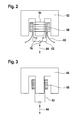
- eine Prinzipskizze einer erfindungsgemäß vorgeschlagenen Tauchspule mit Elektromagnet,
- Figur 3
- eine Ausführungsvariante der in
Figur 2 dargestellten Prinzipskizze, mit Permanentmagnet statt Elektromagnet, - Figur 4
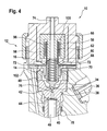
- eine erste Ausführungsform des erfindungsgemäß vorgeschlagenen Linearantriebs in einem Kraftstoffinjektor,
- Figur 5
- eine weitere Ausführungsform des erfindungsgemäß vorgeschlagenen Linearantriebes mit einem Ventilschieber,
- Figur 6
- einen Linear-Antrieb für ein Inline-Magnetventil mit einem lang und schlankbauenden Magnetaktor.
- Der Darstellung gemäß
Figur 1 ist ein aus dem Stand der Technik bekanntes Magnetventil zur Betätigung eines Kraftstoffinjektors zu entnehmen. - Wie
Figur 1 zeigt, umfasst ein Kraftstoffinjektor 10 im Bereich seines Injektorkopfes 12 ein Magnetventil 14. Das Magnetventil 14 umfasst eine Magnetgruppe einer Ankergruppe sowie eine Ventilgruppe. Zur Magnetgruppe zählt ein Magnetkern 18, der eine Durchgangsöffnung aufweist, in der sich eine Schließfeder 16 befindet. In den Magnetkern 18 ist eine Magnetspule 22 eingelassen. Zur Ankergruppe zählt ein Ankerbolzen 32, eine Ankerfiihrung 30 sowie eine am Ankerbolzen bewegbar geführte Ankerplatte 26 mit einer Planseite 28. Die am Ankerbolzen 32 verschieblich geführte Ankerplatte 26 ist über eine Ankerfeder 50 vorgespannt. - Zur Ventilgruppe zählt eine am unteren Ende des Ankerbolzens 32 vorgesehene Kugelführung 34, die ein als Ventilkugel 36 ausgebildetes Wirkelement führt. Das kugelförmig ausgebildete Wirkelement 36 verschließt einen Ablaufkanal mit Ablaufdrossel 42, über welchen ein Steuerraum 40, der in einem Ventilstück 38 ausgebildet ist, druckentlastet werden kann.
- Der Vollständigkeit halber sei erwähnt, dass im oberen Bereich des Ankerbolzens 32 eine Sicherungshülse 20 angebracht ist, die einen in einer Ausnehmung am Umfang des Ankerbolzens 32 eingelassenen Sicherungsring 24 umschließt.
- Die in
Figur 1 dargestellte Schließfeder 16 drückt im unbestromten Zustand des Magnetventiles 14 über den Ankerbolzen 32 auf das z.B. kugelförmig ausgebildete Wirkelement 36. Dieses schließt die Ablaufdrossel 42 des Steuerraumes. Ist das Magnetventil 14 gemäß der Darstellung inFigur 1 hingegen bestromt, zieht die Magnetspule 22 des Magnetventiles 14 die Ankerplatte 26 an, der unter Hochdruck (Systemdruck) stehende Kraftstoff kann über die sich nun öffnende Ablaufdrossel 42 aus dem Steuerraum 40 im Ventilstück 38 in einer niederdruckseitigen Rücklauf entweichen. Durch die Druckentlastung des Steuerraumes 40 wird ein Einspritzventilglied 46 - inFigur 1 nur angedeutet - durch eine Druckstufe, die inFigur 1 nicht dargestellt ist, in Öffnungsrichtung gedrückt. Bei der Hubbewegung des bevorzugt nadelförmig ausgebildeten Ventilgliedes 46 gibt dieses Einspritzöffnungen am brennraumseitigen Ende des Kraftstoffinjektors 10 frei, so dass Kraftstoff in den Brennraum eingespritzt wird, was so lange andauert, bis das Magnetventil 14 wieder in den stromlosen Zustand übergeht. Im stromlosen Zustand wird die Ablaufdrossel 42 durch das kugelförmig ausgebildete Wirkelement 36 wieder geschlossen, so dass sich über der Planseite des Einspritzventilgliedes 46 im Steuerraum 40 des Kraftstoffinjektors 10 wieder Druck aufbaut und das Einspritzventilglied 46 wieder in seinen brennraumseitigen Sitz gedrückt wird. Liegt das bevorzugt nadelförmig ausgebildete Einspritzventilglied 46 im Düsensitz auf, gelangt kein Kraftstoff mehr an die mindestens eine Einspritzöffnung am brennraumseitigen Ende des Kraftstoffinjektors 10 und das Einspritzen von Kraftstoff in den Brennraum ist so lange beendet, bis das Magnetventil 14 erneut bestromt wird. Der Darstellung gemäßFigur 1 ist darüber hinaus entnehmbar, dass die den Ankerbolzen 32 umschließende Ankerführung 30 mit einer Ventilspannmutter 48 im Injektorkörper des Kraftstoffinjektors 10 befestigt ist. - Diese in
Figur 1 dargestellte Hochdruckhydraulik eines Magnetventiles 14 macht Gebrauch vom Flachankerprinzip. Dieses hat sich aufgrund seiner Robustheit bewährt und kann auch in derzeit in der Entwicklung befindlichen Folgegenerationen von Kraftstoffinjektoren 10 Verwendung finden. - Die Dynamik eines Magnetventiles 14 wird neben anderen Parametern durch die Geschwindigkeit bestimmt, mit der ein magnetisches Feld im Eisen aufgebaut wird. Die dabei entstehenden Wirbelströme verzögern den Feldauf- und den Feldabbau des magnetischen Feldes im Eisen. Die Krafterzeugung in einem Magneten basiert auf dem magnetischen Fluss durch Grenzschichten mit unterschiedlicher Permeabilität gemäß der nachfolgenden Beziehungen:


- Der erfindungsgemäß vorgeschlagenen Lösung folgend wird anstelle des vorstehend aufgezeigten Prinzips für den Antrieb einer Hochdrucksteuerung, so zum Beispiel einer Magnet- bzw. einer Ankerbaugruppe des Kraftstoffinjektors 10, ein linearer Antrieb auf Basis der Lorenzkraft eingesetzt werden.
- Diese ergibt sich gemäß der nachfolgenden Beziehung

mit -
F - Lorenzkraft,
- I
- Strom,
- 1
- Länge der Spulenwicklung
- B
- magnetisches Feld.
- Der erfindungsgemäß vorgeschlagene Antrieb arbeitet wie in den
Figuren 2 und 3 , die lediglich Prinzipskizzen mögliche Ausführungsformen der Erfindung enthalten, dargestellt: - In der in
Figur 2 dargestellten Ausführungsform umfasst die Magnetgruppe einen Elektromagneten 52 mit einem M-förmig ausgebildeten Joch. Der mittlere Schenkel des Jochs des Elektromagneten 52 ist von einer Erregerspule 54 umwickelt, deren Anschlüsse mit Bezugszeichen 56 gekennzeichnet sind. Zwischen den beiden äußeren Schenkeln des M-förmig ausgebildeten Jochs des Elektromagneten 52 befindet sich ein Spulenträger 62, an dessen Außenumfang eine Spule 58 angeschlossen ist. Die Spule 58 verfügt über Spulenanschlüsse, die durch Bezugszeichen 60 gekennzeichnet sind. Die Spule 58 wirkt als Tauchspule. Der Elektromagnet 52 erzeugt im Luftspalt einen magnetischen Fluss. In diesem Luftspalt bewegt sich die Spule 58 als Tauchspule, die im bestromten Zustand ebenfalls ein Magnetfeld erzeugt, welche in die Richtung wirkt, die gegen die Ventilfeder (vergleiche Position 16 inFigur 1 ) wirkt. Die Übertragung der erzeugten Magnetkraft erfolgt über eine inFigur 4 dargestellte Ventilfederaufnahme 68. -
Figur 3 zeigt eine Ausführungsform mit einem Permanentmagneten 66, der ebenfalls M-förmig ausgeführt ist. Am Spulenträger 62 befindet sich die Spule 58, die als Tauchspule dient, die Bewegungsrichtung des Spulenkörpers 62 ist durch Bezugszeichen 64 angedeutet. - In den
Figuren 2 und 3 sind die Bewegungsrichtungen 64, in welche sich der Spulenträger 62 mit daran aufgenommener Spule 58 (Tauchspule) bewegt, durch den mit Bezugszeichen 64 bezeichneten Doppelpfeil gekennzeichnet. Aus der Darstellung gemäßFigur 4 geht hervor, dass im Injektorkopf 12 des Kraftstoffinjektors 10 der Permanentmagnet 66 eingelassen ist. Der Permanentmagnet 66 umfasst einen Teil eines mit Bezugszeichen 74 bezeichneten Ablaufkanals, durch den beim Öffnen eines Sitzes 76 aus dem Steuerraum 40 abgesteuerter Kraftstoff in den Niederdruckbereich des Kraftstoffinjektors 10 abströmt. Der Permanentmagnet 66 gemäß der Darstellung inFigur 4 ist rotationssymmetrisch aufgebaut und umfasst ein innenliegendes Joch, welches von einem als Außenring ausgebildeten Joch umschlossen ist. - Zwischen dem zapfenförmig ausgebildeten innenliegenden Joch und dem als Außenring das innenliegende Joch umschließenden Joch befindet sich die Spule 58. Die Spule 58 hat eine ringförmiges Gestalt und ist an einem in der Darstellung gemäß
Figur 4 hülsenförmig beschaffenen Spulenträger 62 aufgenommen. Am unteren Ende ist der in dieser Ausführungsform hülsenförmig ausgebildete Spulenträger 62 mit Spulenanschlüssen 60 versehen, die an Anschlussleitungen 82 angeschlossen sind. In der Darstellung gemäßFigur 4 wirkt die Spule 58, die sich zwischen dem innenliegenden zapfenförmigen Joch und dem als Außenring ausgebildeten außenliegenden Joch definierten Hohlraum befindet, als Tauchspule und kann je nach Bestromung, entweder in vertikale Richtung aufwärts oder in vertikale Richtung abwärts bewegt werden. - Der Spulenträger 62 gemäß der Darstellung in
Figur 4 ist mit einer hülsenförmig ausgebildeten Ventilfederaufnahme 68 verbunden. In der Ventilfederaufnahme 68 befindet sich die Schließfeder 16. Durch geeignete Bestromung der Spule 58 kann diese den Spulenträger 62 und die mit diesem verbundene Ventilfederaufnahme 68 in vertikale Richtung nach oben ziehen, so dass das in der Darstellung gemäßFigur 4 z.B. kugelförmig ausgebildete Wirkelement 36 aus seinem durch Bezugszeichen 76 angedeuteten Sitz gehoben wird. - Aus der in
Figur 4 dargestellten Ausführungsform geht des Weiteren hervor, dass das z.B. kugelförmig ausgebildete Wirkelement 36 in einer Kugelführung 34 am unteren Ende des Ankerbolzens 62 aufgenommen ist. Unterhalb des Sitzes 76 im Ventilstück 38 befindet sich ein Ablaufkanal zur Druckentlastung des Steuerraumes 40. Innerhalb des Ablaufkanals ist die Ablaufdrossel 42 ausgebildet; der Steuerraum 40 wird über eine durch Bezugszeichen 44 gekennzeichnete Zulaufdrossel stets mit unter Systemdruck stehendem Kraftstoff beaufschlagt. Das Ventilstück 38 ist durch einen Dichtring 78 abgedichtet. -
Figur 4 zeigt des Weiteren, dass das Ventilstück 38 im Injektorkörper des Kraftstoffinjektors 10 durch die Ventilspannmutter 48 fixiert ist. Die Ventilfederaufnahme 68, in der die Schließfeder 16 aufgenommen ist, wird ihrerseits von einer Führung 70 umschlossen. Die Führung 70 weist mindestens eine Öffnung 72 auf, über welche abgesteuerte Menge aus dem Steuerraum 40 des Kraftstoffinjektors 10 in den den Permanentmagneten 66 durchziehenden und sich zum Niederdruckbereich des Kraftstoffinjektors 10 erstreckenden Ablauf kanal 74 abgesteuert werden kann. Die Führung 70 ist einerseits durch den Deckel des Magnetventiles 14 und andererseits vom Injektorkörper des Kraftstoffinjektors 10 umschlossen und im Kraftstoffinj ektor 10 fixiert. - Auf den Spulenträger 62 ist die Spule 58 (Tauchspule) gewickelt, die bei entsprechender Drahtlänge und Bestromung einen ausreichenden magnetischen Fluss erzeugt, derart, dass eine Kraft erzeugt wird, die größer ist als die durch die Ventilfeder 16 erzeugte Schließkraft. Der Spulenträger 62 ist mit der Ventilfederaufnahme 68 fest verbunden, so dass eine Kraftübertragung jederzeit stattfinden kann.
- Für eine Ausrichtung der Ventilfederaufnahme 68 zum Permanentmagneten 66 als auch zum Magnetventil 16 sorgt die Führung 70. In dieser ist die Ventilfederaufnahme 68 mit minimalem Radialspiel geführt. Der Ankerhub wird beispielsweise über eine Einstellscheibe eingestellt, die zwischen dem Injektorkörper und der Führung 70 eingebaut wird. Die Kontaktierung der Spule 58 erfolgt zum Beispiel durch flexible Kontaktierungen 60, die zum Beispiel durch ein Gewebe verstärkt sein können. Alternativ kann der elektrische Anschluss auch über Schleifkontakte, wie zum Beispiel am Kommutator von Elektromotoren eingesetzt, ersetzt werden. In der Einhausung des Permanentmagneten 66 sind Leitungen vom Injektoranschlussstecker bis zu den flexiblen Leitungen integriert. Die Verbindung der integrierten Anschlussleitung 82 mit den flexiblen Spulenanschlüssen 60 kann zum Beispiel über einen Steckerkontakt oder dergleichen erfolgen.
- Der Magnetkopf wird durch eine Magnetspannmutter gegen den Injektorkörper verspannt und drückt gleichzeitig die Führung 70 gegen den Injektorkörper 102. Der Rücklauf durch die Ankerbaugruppe kann an verschiedenen Stellen erfolgen, wie zum Beispiel über Bohrungen in der Ventilfederaufnahme 68, an der Unterseite oder durch den Spulenträger 62 über Ausschnitte gelegt werden. In
Figur 4 ist eine Ausführungsform mit Permanentmagnet 66 gemäßFigur 3 angedeutet; anstelle des inFigur 4 dargestellten Permanentmagneten 66 kann aber auch der inFigur 2 dargestellte Elektromagnet 52 eingesetzt werden. -
Figur 5 ist eine weitere Ausführungsform des erfindungsgemäß vorgeschlagenen Linearantriebs zur Betätigung eines Kraftstoffinjektors zu entnehmen. - Auch gemäß der Darstellung in
Figur 5 umfasst der Kraftstoffinjektor 10 den Injektorkopf 12, innerhalb dessen sich ein Magnetventil 14 befindet. Das Magnetventil 14 umfasst seinerseits den Permanentmagneten 66, der ein im Wesentlichen zapfenförmig ausgebildetes Innenjoch umfasst, welches vom Ablaufkanal 74 durchzogen ist. Unter Ausbildung eines Freiraumes ist am Permanentmagneten 66 ein das zapfenförmig ausgebildete Innenjoch umschließendes Außenjoch ausgebildet. Im Freiraum zwischen dem zapfenförmig ausgebildeten Innenjoch und dem Außenjoch befindet sich der Spulenträger 62, an dessen Außenmantelfläche die Spule 58 befestigt ist. Die Spule 58 bzw. deren Spulenanschlüsse 60 sind an einem scheibenförmig ausgebildeten Stecker 80 kontaktiert, der seinerseits über sich durch den Deckel des Magnetventiles 14 erstreckende Anschlussleitungen 82 elektrisch kontaktiert ist. - Mittels einer Überwurfmutter ist der Deckel des Magnetventils 14 mit dem Injektorkörper des Kraftstoffinjektors 10 verbunden. Ähnlich wie in der in
Figur 4 dargestellten Ausführungsform ist der hülsenförmig ausgebildete Spulenträger 62, der die Spule 58 (Tauchspule) aufnimmt, mit einem Ventilschieber 84 verbunden. Der Ventilschieber 84 entspricht in etwa der inFigur 4 dargestellten Ventilfederaufnahme 68 und umschließt die Ventilfeder 16. Die Ventilfeder 16 ist in den Ventilschieber 84 eingelassen und stützt sich mit ihrem oberen Ende am zapfenförmig ausgebildeten, innenliegenden Joch des Permanentmagneten 66, welches vom Ablaufkanal 74 durchzogen ist, ab. - Des Weiteren umfasst die in
Figur 5 dargestellte Ausführungsform des erfindunsgemäß vorgeschlagenen Kraftstoffinjektors 10 das Ventilstück 38, welches durch Steuerraum 40 begrenzt. Im Gegensatz zur Ausführungsform des Ventilstücks 38 gemäßFigur 4 befindet sich an der oberen Planseite des Ventilstücks 38 ein Bolzenansatz 90, welcher in einen Bolzen übergeht, an dem der Ventilschieber 84 innen geführt ist. An der Außenseite des Ventilschiebers 84 ist ein Bund ausgebildet, der mit einem von der Ventilspannmutter 84 auf einem Einstellring 88 fixierten Ankerhubanschlag 86 zusammenwirkt. Der Ankerhubanschlag 86 ist im Wesentlichen ringförmig ausgebildet und weist einen Innendurchmesser auf, der kleiner ist als der Innendurchmesser des Einstellringes 88, auf dem sich der Ankerhubanschlag 86 abstützt. Der Innendurchmesser des im Wesentlichen scheibenförmig ausgebildeten Ankerhubanschlages 86 ist wiederum so bemessen, dass ein an der Außenmantelfläche des Ventilschiebers 84 ausgebildeter Bund am Ankerhubanschlag 86 anschlägt. Der Ventilschieber 84 schließt oder öffnet einen hydraulischen Raum oberhalb des Sitzes 76. In diesen hydraulischen Raum mündet die Ablaufdrossel 42 zur Druckentlastung des Steuerraumes 40. Der Steuerraum 40 seinerseits ist stets über die Zulaufdrossel 44 mit unter Systemsdruck stehendem Kraftstoff beaufschlagt. Je nach Druckentlastung oder Druckbeaufschlagung des Steuerraums 40 bewegt sich das im Wesentlichen nadelförmig ausgebildete - inFigur 5 nur teilweise dargestellte - Einspritzventilglied 46 in vertikale Richtung nach oben und öffnet die Einspritzöffnung am brennraumseitigen Ende des Kraftstoffinjektors 10 bzw. nach unten in den Sitz des Einspritzventilgliedes 46, so dass mindestens eine am brennraumseitigen Ende des Kraftstoffinjektors 10 ausgebildete Einspritzöffnung wieder verschlossen wird. - Wie sich des Weiteren aus der Darstellung gemäß
Figur 5 ergibt, umfasst der Permanentmagnet 66 ein zapfenförmig ausgebildetes Innenjoch 56, welches von dem Ablaufkanal 74 in vertikaler Richtung durchzogen ist. Der Ablaufkanal 74 kann auch außerhalb des Magnetkerns verlaufend angeordnet sein. Darüber hinaus ist am Permanentmagneten 66 analog zur Darstellung gemäßFigur 4 ein ringförmiges Außenjoch 98 ausgebildet. Zwischen dem Innenjoch 96 und dem Außenjoch 98 des Permanentmagneten 66 befindet sich ein Hohlraum 100. Der Hohlraum 100 stellt den Raum dar, innerhalb dessen sich die an der Außenumfangsfläche des Spulenträgers 62 befindliche Spule 58 als Tauchspule in vertikale Richtung nach oben oder nach unten bewegt. Mit Bezugszeichen 102 ist der Injektorkörper des Kraftstoffinjektors 10 bezeichnet. - Aus der Darstellung gemäß
Figur 6 geht eine schlankbauende Ausführungsvariante des erfindungsgemäß vorgeschlagenen Linearantriebes zur Betätigung eines Kraftstoffinjektors hervor. - Wie sich der Darstellung gemäß
Figur 6 entnehmen lässt, ist die Formgebung der Spule 58 und des Permanentmagneten 66 so flexibel, dass ein Inline-Magnetventil - wie inFigur 6 dargestellt - geschaffen werden kann. Der in einer großen Bauhöhe H ausgebildete Permanentmagnet 66 weist einen Durchmesser D auf, welcher um ein Vielfaches kleiner ist als die Bauhöhe. Der inFigur 6 dargestellte Linearantrieb lässt sich im Injektorkörper 102 des Kraftstoffinjektors 10 unterbringen und kann zum Beispiel als Substitution des bisher verbauten Piezoaktors dienen. Aufgrund der schlankbauenden Geometrie des inFigur 6 dargestellten Permanentmagneten 66 ergibt sich ein langbauender Spulenträger 62, auf dessen Umfangsmantelfläche die als Tauchspule dienende Spule 58 gewickelt ist. Auch bei der Ausführungsform des Permanentmagneten 66 gemäß der Ausführungsform inFigur 6 umfasst der Permanentmagnet 66 ein Innenjoch 96 sowie ein dieses ringförmig umschließendes Außenjoch 58. Zwischen dem Innenjoch 96 und dem Außenjoch 98 befindet sich der Hohlraum 100, in welchem die Spule 58, aufgenommen am Spulenträger 62, vertikal bewegbar untergebracht ist. Auch in der inFigur 6 dargestellten Ausführungsform (Inline-Magnetventil) bewegt sich der Spulenträger 62 entsprechend des Doppelpfeiles 64 je nach Bestromung der Spule 58 in vertikale Bewegungsrichtung nach oben oder nach unten. Der Vollständigkeit halber sei erwähnt, dass der Injektorkörper 102 des inFigur 6 dargestellten Kraftstoffinjektors 10 von einer Hochdruckleitung 92 durchzogen ist und das Außenjoch 98 des Permanentmagneten 66 sich an einer Stützkante 94 abstützt, die im Injektorkörper 102 ausgebildet ist. - Der vorstehend anhand der in den
Figuren 2 bis 6 gezeigten Ausführungsformen beschriebene Linearantrieb zeichnet sich gegenüber aus dem Stand der Technik bekannten Magnetventilen dadurch aus, dass diese wenige Einzelteile umfasst und die Verlustleistung des Magnetventiles erheblich geringer ist als die des Magnetventiles 14, welches im Kraftstoffinjektor 10 gemäßFigur 1 Anwendung findet. Des Weiteren weist der erfindungsgemäß vorgeschlagene Linearantrieb gemäß der Ausführungsvarianten in denFiguren 2 bis 6 eine kleinere elektrische Zeitkonstante und kleinere bewegte Massen der Teile auf, so dass sich ein hochdynamischer Antrieb realisieren lässt. Wie insbesondere aus der Darstellung gemäßFigur 6 hervorgeht, lässt sich ein extrem schlankbauendes Magnetventil realisieren, so dass es den bisher an Kraftstoffinjektoren eingesetzten relativ teuren Piezoaktor ersetzen kann, da die Bauräume des schlankbauenden Magnetventiles gemäß der Darstellung inFigur 6 und des Piezoaktors in etwas vergleichbar sind, so dass sich eine Inline-Magnetventilrealisierung erreichen lässt. Des Weiteren ist ein umständliche sowie zeitraubende und darüber hinaus schwer automatisierbare Restluftspalteinstellung beim im erfindungsgemäß vorgeschlagenen Linearantrieb verzichtbar. Im Gegensatz zu bisher eingesetzten Magneten kann bei dem erfindungsgemäß vorgeschlagenen Linearantrieb der Kraftvektor umgekehrt werden. - Des Weiteren ist durch die erfindungsgemäß vorgeschlagene Lösung bei einer ausreichenden Dimensionierung der als Tauchspule eingesetzten Spule 58 und des Permanentmagneten 66 eine direkte Ansteuerung des nadelförmig ausgebildeten Einspritzventilgliedes 46 möglich. Mit dieser Ausführungsvariante kann die gesamte Hochdruckhydraulik, d. h. das Befüllen und Druckentlasten des Steuerraumes 40 gemäß den Ausführungsformen, die in den
Figuren 4 und5 dargestellt sind, entfallen und die Kraft des Spulenträgers 62 direkt auf das nadelförmig ausgebildete Einspritzventilglied 46 übertragen werden.
Claims (12)
- Kraftstoffinjektor (10) mit einem Magnetventil (14), über dessen Betätigung ein Wirkelement (36, 84) aus seinem Sitz (76) bewegt wird oder in seinen Sitz gestellt wird, zur Druckentlastung oder Druckbeaufschlagung eines Steuerraumes (40), dadurch gekennzeichnet, dass das Magnetventil (14) einen Magneten (52, 66) umfasst, der eine Spule (58) enthält, die über einen Spulenträger (62) das Wirkelement (36, 84) betätigt, indem der Spulenträger (62) mit dem Wirkelement (36, 84) verbunden ist und die Spule (58) als Tauchspule auf der Außenumfangsfläche des Spulenträgers (62) gewickelt ist und in einem Hohlraum (100) eines als Permanentmagnet (66) oder als Elektromagnet (52) ausgebildeten Magneten eintaucht.
- Kraftstoffinjektor (10) gemäß Anspruch 1, dadurch gekennzeichnet, dass die Spule (58) auf der Umfangsfläche des Spulenträgers (62) angeordnet ist.
- Kraftstoffinjektor (10) gemäß Anspruch 1, dadurch gekennzeichnet, dass das Wirkelement (36) kugelförmig ausgebildet ist und sich an einer Ventilfederaufnahme (68) befindet.
- Kraftstoffinjektor (10) gemäß Anspruch 1, dadurch gekennzeichnet, dass das Wirkelement (84) an einem Bolzen eines Ventilstücks (38) geführt ist.
- Kraftstoffinjektor (10) gemäß Anspruch 1, dadurch gekennzeichnet, dass der Permanentmagnet (66) oder der Elektromagnet (52) zumindest ein Innenjoch (96) und ein dieses ringförmig umschließendes Außenjoch (98) umfasst, zwischen denen der Hohlraum (100) gebildet ist.
- Kraftstoffinjektor (10) gemäß Anspruch 3, dadurch gekennzeichnet, dass die Ventilfederaufnahme (68) in einer Führung (70) geführt ist.
- Kraftstoffinjektor (10) gemäß einem der vorhergehenden Ansprüche, dadurch gekennzeichnet, dass die Spule (58) über flexible Spulenanschlüsse (60) mit Anschlussleitungen (82) elektrisch verbunden ist.
- Kraftstoffinjektor (10) gemäß Anspruch 1, dadurch gekennzeichnet, dass im Permanentmagneten (66) ein Ablaufkanal (74) zum niederdruckseitigen Rücklauf ausgebildet ist.
- Kraftstoffinjektor (10) gemäß Anspruch 1, dadurch gekennzeichnet, dass die als Tauchspule dienende Spule (58) mit ihren Spulenanschlüssen (60) an einem scheibenförmig ausgebildeten Steckerelement (80) kontaktiert ist.
- Kraftstoffinjektor (10) gemäß Anspruch 4, dadurch gekennzeichnet, dass das Wirkelement (84) einen Bund (85) aufweist, der mit einem im Injektorkörper (102) fixierten scheibenförmig ausgebildeten Ankerhubanschlag (86) zusammenwirkt.
- Kraftstoffinjektor (10) gemäß Anspruch 4, dadurch gekennzeichnet, dass das Wirkelement (84) die Schließfeder (16) aufnimmt und an einem bolzenförmigen Fortsatz des Ventilstücks (38) in axiale Richtung geführt ist.
- Kraftstoffinjektor (10) gemäß einem der vorhergehenden Ansprüche, dadurch gekennzeichnet, dass der Magnet (52, 66) eine Höhe (H) aufweist, die um ein vielfaches höher ist als ein Durchmesser (D) des Magneten (52, 66).
Applications Claiming Priority (1)
| Application Number | Priority Date | Filing Date | Title |
|---|---|---|---|
| DE102007027185A DE102007027185A1 (de) | 2007-06-13 | 2007-06-13 | Kraftstoffinjektor mit Linearantrieb |
Publications (2)
| Publication Number | Publication Date |
|---|---|
| EP2003326A1 EP2003326A1 (de) | 2008-12-17 |
| EP2003326B1 true EP2003326B1 (de) | 2010-04-21 |
Family
ID=39810200
Family Applications (1)
| Application Number | Title | Priority Date | Filing Date |
|---|---|---|---|
| EP08104105A Not-in-force EP2003326B1 (de) | 2007-06-13 | 2008-05-27 | Kraftstoffinjektor mit Linearantrieb |
Country Status (3)
| Country | Link |
|---|---|
| EP (1) | EP2003326B1 (de) |
| AT (1) | ATE465341T1 (de) |
| DE (2) | DE102007027185A1 (de) |
Cited By (1)
| Publication number | Priority date | Publication date | Assignee | Title |
|---|---|---|---|---|
| DE102013110029C5 (de) * | 2013-09-12 | 2017-03-16 | Bürkert Werke GmbH | Elektrodynamischer Aktor |
Families Citing this family (5)
| Publication number | Priority date | Publication date | Assignee | Title |
|---|---|---|---|---|
| DE102005029100B4 (de) * | 2005-06-23 | 2016-11-10 | Robert Bosch Gmbh | Brennstoffeinspritzventil |
| ITBO20110569A1 (it) * | 2011-10-05 | 2013-04-06 | Magneti Marelli Spa | Iniettore elettromagnetico di carburante con bobina mobile |
| DE102012206213A1 (de) | 2012-04-16 | 2013-10-17 | Robert Bosch Gmbh | Kraftstoffinjektor mit Magnetventil |
| CN114458503B (zh) * | 2022-03-09 | 2022-09-02 | 哈尔滨工程大学 | 一种多永磁-电磁耦合磁路的高响应高速电磁阀 |
| GB2624454B (en) * | 2022-11-18 | 2025-05-14 | Clean Air Power Gt Ltd | Fuel injector |
Family Cites Families (7)
| Publication number | Priority date | Publication date | Assignee | Title |
|---|---|---|---|---|
| GB9508623D0 (en) * | 1995-04-28 | 1995-06-14 | Lucas Ind Plc | "Fuel injection nozzle" |
| DE19650865A1 (de) | 1996-12-07 | 1998-06-10 | Bosch Gmbh Robert | Magnetventil |
| DE19708104A1 (de) | 1997-02-28 | 1998-09-03 | Bosch Gmbh Robert | Magnetventil |
| DE602004004254T2 (de) * | 2004-06-30 | 2007-07-12 | C.R.F. S.C.P.A. | Servoventil zum Steuern eines Einspritzventils einer Brennkraftmaschine |
| JP2006194237A (ja) * | 2004-12-14 | 2006-07-27 | Denso Corp | 電磁式アクチュエータ |
| JP2006307831A (ja) * | 2005-03-29 | 2006-11-09 | Denso Corp | 燃料噴射弁 |
| DE102005024045A1 (de) * | 2005-05-25 | 2006-11-30 | Robert Bosch Gmbh | Injektor für ein Kraftstoffeinspritzsystem |
-
2007
- 2007-06-13 DE DE102007027185A patent/DE102007027185A1/de not_active Withdrawn
-
2008
- 2008-05-27 DE DE502008000549T patent/DE502008000549D1/de active Active
- 2008-05-27 EP EP08104105A patent/EP2003326B1/de not_active Not-in-force
- 2008-05-27 AT AT08104105T patent/ATE465341T1/de active
Cited By (2)
| Publication number | Priority date | Publication date | Assignee | Title |
|---|---|---|---|---|
| DE102013110029C5 (de) * | 2013-09-12 | 2017-03-16 | Bürkert Werke GmbH | Elektrodynamischer Aktor |
| US10396646B2 (en) | 2013-09-12 | 2019-08-27 | Buerkert Werke Gmbh | Micro value comprising an electrodynamic actuator having stationary magnet arrangement and a moveable air-core coil |
Also Published As
| Publication number | Publication date |
|---|---|
| DE102007027185A1 (de) | 2009-01-08 |
| ATE465341T1 (de) | 2010-05-15 |
| EP2003326A1 (de) | 2008-12-17 |
| DE502008000549D1 (de) | 2010-06-02 |
Similar Documents
| Publication | Publication Date | Title |
|---|---|---|
| DE102007044877B4 (de) | Fluid-Einspritzventil | |
| DE19932548B4 (de) | Dualelektromagneten mit einer Einzelschaltung und Brennstoffeinspritzvorrichtung, die diese anwendet | |
| DE69406780T2 (de) | Stossgedämpfte anker- und nadelventilanordnung | |
| DE102010004397B4 (de) | Statorbaugruppe und diese nutzender Kraftstoffinjektor | |
| EP2003326A1 (de) | Kraftstoffinjektor mit Linearantrieb | |
| DE102007056913A1 (de) | Einspritzdüse für Kraftstoff mit Kugelventil | |
| DE202008008650U1 (de) | Magnetkern, Magnetbaugruppe sowie Kraftstoff-Injektor-Magnetventil | |
| WO2008101535A1 (de) | Fluid-einspritzventil | |
| EP2914842B1 (de) | Aktor | |
| DE102005059228A1 (de) | Elektromagnetische Betätigungsvorrichtung für ein Kraftstoffeinspritzventil | |
| EP2428672A2 (de) | Kraftstoffinjektor | |
| WO2016012143A1 (de) | Elektromagnetische stelleinheit für ein saugventil sowie saugventil | |
| DE102006061946B4 (de) | Brennstoffeinspritzventil | |
| DE102006061947A1 (de) | Brennstoffeinspritzventil | |
| DE102008010561A1 (de) | Einspritzventil mit Magnetverklebung | |
| WO2011101174A1 (de) | Elektromagnetischer aktor | |
| WO2003058052A1 (de) | Steuerteil für injektoren mit schaltbarer düsennadel | |
| DE102014226367A1 (de) | Brennstoffeinspritzventil | |
| WO2008083882A1 (de) | Injektor zum einspritzen von kraftstoff | |
| DE102004051138B4 (de) | Druckverstärkendes Brennstoff-Einspritzventil | |
| WO2017167646A1 (de) | Aktorbaugruppe für ein kraftstoffeinspritzventil, kraftstoffeinspritzventil | |
| DE102011076956A1 (de) | Kraftstoffinjektor | |
| DE102020108665A1 (de) | Düsennadel für einen Kraftstoffinjektor und Injektorgehäuse für eine Düsennadel | |
| EP2201238B1 (de) | Streuflussreduzierter anker | |
| DE102020108668A1 (de) | Nadelhubschalter und Kraftstoffinjektor mit einem solchen Nadelhubschalter |
Legal Events
| Date | Code | Title | Description |
|---|---|---|---|
| PUAI | Public reference made under article 153(3) epc to a published international application that has entered the european phase |
Free format text: ORIGINAL CODE: 0009012 |
|
| AK | Designated contracting states |
Kind code of ref document: A1 Designated state(s): AT BE BG CH CY CZ DE DK EE ES FI FR GB GR HR HU IE IS IT LI LT LU LV MC MT NL NO PL PT RO SE SI SK TR |
|
| AX | Request for extension of the european patent |
Extension state: AL BA MK RS |
|
| 17P | Request for examination filed |
Effective date: 20090617 |
|
| 17Q | First examination report despatched |
Effective date: 20090723 |
|
| AKX | Designation fees paid |
Designated state(s): AT BE BG CH CY CZ DE DK EE ES FI FR GB GR HR HU IE IS IT LI LT LU LV MC MT NL NO PL PT RO SE SI SK TR |
|
| GRAP | Despatch of communication of intention to grant a patent |
Free format text: ORIGINAL CODE: EPIDOSNIGR1 |
|
| GRAS | Grant fee paid |
Free format text: ORIGINAL CODE: EPIDOSNIGR3 |
|
| GRAA | (expected) grant |
Free format text: ORIGINAL CODE: 0009210 |
|
| AK | Designated contracting states |
Kind code of ref document: B1 Designated state(s): AT BE BG CH CY CZ DE DK EE ES FI FR GB GR HR HU IE IS IT LI LT LU LV MC MT NL NO PL PT RO SE SI SK TR |
|
| REG | Reference to a national code |
Ref country code: GB Ref legal event code: FG4D Free format text: NOT ENGLISH |
|
| REG | Reference to a national code |
Ref country code: CH Ref legal event code: EP |
|
| REG | Reference to a national code |
Ref country code: IE Ref legal event code: FG4D Free format text: LANGUAGE OF EP DOCUMENT: GERMAN |
|
| REF | Corresponds to: |
Ref document number: 502008000549 Country of ref document: DE Date of ref document: 20100602 Kind code of ref document: P |
|
| REG | Reference to a national code |
Ref country code: NL Ref legal event code: VDEP Effective date: 20100421 |
|
| LTIE | Lt: invalidation of european patent or patent extension |
Effective date: 20100421 |
|
| PG25 | Lapsed in a contracting state [announced via postgrant information from national office to epo] |
Ref country code: SE Free format text: LAPSE BECAUSE OF FAILURE TO SUBMIT A TRANSLATION OF THE DESCRIPTION OR TO PAY THE FEE WITHIN THE PRESCRIBED TIME-LIMIT Effective date: 20100421 Ref country code: LT Free format text: LAPSE BECAUSE OF FAILURE TO SUBMIT A TRANSLATION OF THE DESCRIPTION OR TO PAY THE FEE WITHIN THE PRESCRIBED TIME-LIMIT Effective date: 20100421 Ref country code: NL Free format text: LAPSE BECAUSE OF FAILURE TO SUBMIT A TRANSLATION OF THE DESCRIPTION OR TO PAY THE FEE WITHIN THE PRESCRIBED TIME-LIMIT Effective date: 20100421 Ref country code: NO Free format text: LAPSE BECAUSE OF FAILURE TO SUBMIT A TRANSLATION OF THE DESCRIPTION OR TO PAY THE FEE WITHIN THE PRESCRIBED TIME-LIMIT Effective date: 20100721 Ref country code: ES Free format text: LAPSE BECAUSE OF FAILURE TO SUBMIT A TRANSLATION OF THE DESCRIPTION OR TO PAY THE FEE WITHIN THE PRESCRIBED TIME-LIMIT Effective date: 20100801 |
|
| REG | Reference to a national code |
Ref country code: IE Ref legal event code: FD4D |
|
| BERE | Be: lapsed |
Owner name: ROBERT BOSCH G.M.B.H. Effective date: 20100531 |
|
| PG25 | Lapsed in a contracting state [announced via postgrant information from national office to epo] |
Ref country code: SI Free format text: LAPSE BECAUSE OF FAILURE TO SUBMIT A TRANSLATION OF THE DESCRIPTION OR TO PAY THE FEE WITHIN THE PRESCRIBED TIME-LIMIT Effective date: 20100421 Ref country code: LV Free format text: LAPSE BECAUSE OF FAILURE TO SUBMIT A TRANSLATION OF THE DESCRIPTION OR TO PAY THE FEE WITHIN THE PRESCRIBED TIME-LIMIT Effective date: 20100421 Ref country code: IS Free format text: LAPSE BECAUSE OF FAILURE TO SUBMIT A TRANSLATION OF THE DESCRIPTION OR TO PAY THE FEE WITHIN THE PRESCRIBED TIME-LIMIT Effective date: 20100821 Ref country code: HR Free format text: LAPSE BECAUSE OF FAILURE TO SUBMIT A TRANSLATION OF THE DESCRIPTION OR TO PAY THE FEE WITHIN THE PRESCRIBED TIME-LIMIT Effective date: 20100421 Ref country code: FI Free format text: LAPSE BECAUSE OF FAILURE TO SUBMIT A TRANSLATION OF THE DESCRIPTION OR TO PAY THE FEE WITHIN THE PRESCRIBED TIME-LIMIT Effective date: 20100421 |
|
| PG25 | Lapsed in a contracting state [announced via postgrant information from national office to epo] |
Ref country code: PL Free format text: LAPSE BECAUSE OF FAILURE TO SUBMIT A TRANSLATION OF THE DESCRIPTION OR TO PAY THE FEE WITHIN THE PRESCRIBED TIME-LIMIT Effective date: 20100421 Ref country code: MC Free format text: LAPSE BECAUSE OF NON-PAYMENT OF DUE FEES Effective date: 20100531 Ref country code: CY Free format text: LAPSE BECAUSE OF FAILURE TO SUBMIT A TRANSLATION OF THE DESCRIPTION OR TO PAY THE FEE WITHIN THE PRESCRIBED TIME-LIMIT Effective date: 20100602 |
|
| PG25 | Lapsed in a contracting state [announced via postgrant information from national office to epo] |
Ref country code: DK Free format text: LAPSE BECAUSE OF FAILURE TO SUBMIT A TRANSLATION OF THE DESCRIPTION OR TO PAY THE FEE WITHIN THE PRESCRIBED TIME-LIMIT Effective date: 20100421 Ref country code: EE Free format text: LAPSE BECAUSE OF FAILURE TO SUBMIT A TRANSLATION OF THE DESCRIPTION OR TO PAY THE FEE WITHIN THE PRESCRIBED TIME-LIMIT Effective date: 20100421 Ref country code: IE Free format text: LAPSE BECAUSE OF FAILURE TO SUBMIT A TRANSLATION OF THE DESCRIPTION OR TO PAY THE FEE WITHIN THE PRESCRIBED TIME-LIMIT Effective date: 20100421 |
|
| PLBE | No opposition filed within time limit |
Free format text: ORIGINAL CODE: 0009261 |
|
| STAA | Information on the status of an ep patent application or granted ep patent |
Free format text: STATUS: NO OPPOSITION FILED WITHIN TIME LIMIT |
|
| PG25 | Lapsed in a contracting state [announced via postgrant information from national office to epo] |
Ref country code: SK Free format text: LAPSE BECAUSE OF FAILURE TO SUBMIT A TRANSLATION OF THE DESCRIPTION OR TO PAY THE FEE WITHIN THE PRESCRIBED TIME-LIMIT Effective date: 20100421 Ref country code: RO Free format text: LAPSE BECAUSE OF FAILURE TO SUBMIT A TRANSLATION OF THE DESCRIPTION OR TO PAY THE FEE WITHIN THE PRESCRIBED TIME-LIMIT Effective date: 20100421 Ref country code: CZ Free format text: LAPSE BECAUSE OF FAILURE TO SUBMIT A TRANSLATION OF THE DESCRIPTION OR TO PAY THE FEE WITHIN THE PRESCRIBED TIME-LIMIT Effective date: 20100421 |
|
| 26N | No opposition filed |
Effective date: 20110124 |
|
| PG25 | Lapsed in a contracting state [announced via postgrant information from national office to epo] |
Ref country code: BE Free format text: LAPSE BECAUSE OF NON-PAYMENT OF DUE FEES Effective date: 20100531 |
|
| PG25 | Lapsed in a contracting state [announced via postgrant information from national office to epo] |
Ref country code: MT Free format text: LAPSE BECAUSE OF FAILURE TO SUBMIT A TRANSLATION OF THE DESCRIPTION OR TO PAY THE FEE WITHIN THE PRESCRIBED TIME-LIMIT Effective date: 20100421 |
|
| PG25 | Lapsed in a contracting state [announced via postgrant information from national office to epo] |
Ref country code: GR Free format text: LAPSE BECAUSE OF FAILURE TO SUBMIT A TRANSLATION OF THE DESCRIPTION OR TO PAY THE FEE WITHIN THE PRESCRIBED TIME-LIMIT Effective date: 20100722 |
|
| PG25 | Lapsed in a contracting state [announced via postgrant information from national office to epo] |
Ref country code: PT Free format text: LAPSE BECAUSE OF FAILURE TO SUBMIT A TRANSLATION OF THE DESCRIPTION OR TO PAY THE FEE WITHIN THE PRESCRIBED TIME-LIMIT Effective date: 20100921 Ref country code: HU Free format text: LAPSE BECAUSE OF FAILURE TO SUBMIT A TRANSLATION OF THE DESCRIPTION OR TO PAY THE FEE WITHIN THE PRESCRIBED TIME-LIMIT Effective date: 20101022 Ref country code: LU Free format text: LAPSE BECAUSE OF NON-PAYMENT OF DUE FEES Effective date: 20100527 Ref country code: BG Free format text: LAPSE BECAUSE OF FAILURE TO SUBMIT A TRANSLATION OF THE DESCRIPTION OR TO PAY THE FEE WITHIN THE PRESCRIBED TIME-LIMIT Effective date: 20100421 |
|
| PG25 | Lapsed in a contracting state [announced via postgrant information from national office to epo] |
Ref country code: TR Free format text: LAPSE BECAUSE OF FAILURE TO SUBMIT A TRANSLATION OF THE DESCRIPTION OR TO PAY THE FEE WITHIN THE PRESCRIBED TIME-LIMIT Effective date: 20100421 |
|
| REG | Reference to a national code |
Ref country code: CH Ref legal event code: PL |
|
| GBPC | Gb: european patent ceased through non-payment of renewal fee |
Effective date: 20120527 |
|
| PG25 | Lapsed in a contracting state [announced via postgrant information from national office to epo] |
Ref country code: LI Free format text: LAPSE BECAUSE OF NON-PAYMENT OF DUE FEES Effective date: 20120531 Ref country code: CH Free format text: LAPSE BECAUSE OF NON-PAYMENT OF DUE FEES Effective date: 20120531 |
|
| PG25 | Lapsed in a contracting state [announced via postgrant information from national office to epo] |
Ref country code: GB Free format text: LAPSE BECAUSE OF NON-PAYMENT OF DUE FEES Effective date: 20120527 |
|
| PGFP | Annual fee paid to national office [announced via postgrant information from national office to epo] |
Ref country code: FR Payment date: 20130604 Year of fee payment: 6 Ref country code: IT Payment date: 20130525 Year of fee payment: 6 |
|
| PG25 | Lapsed in a contracting state [announced via postgrant information from national office to epo] |
Ref country code: BG Free format text: LAPSE BECAUSE OF FAILURE TO SUBMIT A TRANSLATION OF THE DESCRIPTION OR TO PAY THE FEE WITHIN THE PRESCRIBED TIME-LIMIT Effective date: 20100721 |
|
| REG | Reference to a national code |
Ref country code: AT Ref legal event code: MM01 Ref document number: 465341 Country of ref document: AT Kind code of ref document: T Effective date: 20130527 |
|
| PG25 | Lapsed in a contracting state [announced via postgrant information from national office to epo] |
Ref country code: AT Free format text: LAPSE BECAUSE OF NON-PAYMENT OF DUE FEES Effective date: 20130527 |
|
| REG | Reference to a national code |
Ref country code: FR Ref legal event code: ST Effective date: 20150130 |
|
| PG25 | Lapsed in a contracting state [announced via postgrant information from national office to epo] |
Ref country code: IT Free format text: LAPSE BECAUSE OF NON-PAYMENT OF DUE FEES Effective date: 20140527 |
|
| PG25 | Lapsed in a contracting state [announced via postgrant information from national office to epo] |
Ref country code: FR Free format text: LAPSE BECAUSE OF NON-PAYMENT OF DUE FEES Effective date: 20140602 |
|
| PGFP | Annual fee paid to national office [announced via postgrant information from national office to epo] |
Ref country code: DE Payment date: 20190716 Year of fee payment: 12 |
|
| REG | Reference to a national code |
Ref country code: DE Ref legal event code: R119 Ref document number: 502008000549 Country of ref document: DE |
|
| PG25 | Lapsed in a contracting state [announced via postgrant information from national office to epo] |
Ref country code: DE Free format text: LAPSE BECAUSE OF NON-PAYMENT OF DUE FEES Effective date: 20201201 |