EP2003092B1 - Appareil de production de trichlorosilane - Google Patents
Appareil de production de trichlorosilane Download PDFInfo
- Publication number
- EP2003092B1 EP2003092B1 EP07830459.9A EP07830459A EP2003092B1 EP 2003092 B1 EP2003092 B1 EP 2003092B1 EP 07830459 A EP07830459 A EP 07830459A EP 2003092 B1 EP2003092 B1 EP 2003092B1
- Authority
- EP
- European Patent Office
- Prior art keywords
- reaction
- gas
- supply
- reaction vessel
- passageway
- Prior art date
- Legal status (The legal status is an assumption and is not a legal conclusion. Google has not performed a legal analysis and makes no representation as to the accuracy of the status listed.)
- Active
Links
- ZDHXKXAHOVTTAH-UHFFFAOYSA-N trichlorosilane Chemical compound Cl[SiH](Cl)Cl ZDHXKXAHOVTTAH-UHFFFAOYSA-N 0.000 title claims description 40
- 239000005052 trichlorosilane Substances 0.000 title claims description 40
- 238000004519 manufacturing process Methods 0.000 title description 4
- 238000006243 chemical reaction Methods 0.000 claims description 157
- 239000007789 gas Substances 0.000 claims description 146
- 239000007795 chemical reaction product Substances 0.000 claims description 51
- XKRFYHLGVUSROY-UHFFFAOYSA-N Argon Chemical compound [Ar] XKRFYHLGVUSROY-UHFFFAOYSA-N 0.000 claims description 43
- 238000010438 heat treatment Methods 0.000 claims description 23
- 229910052786 argon Inorganic materials 0.000 claims description 22
- OKTJSMMVPCPJKN-UHFFFAOYSA-N Carbon Chemical compound [C] OKTJSMMVPCPJKN-UHFFFAOYSA-N 0.000 claims description 14
- 229910052799 carbon Inorganic materials 0.000 claims description 14
- VXEGSRKPIUDPQT-UHFFFAOYSA-N 4-[4-(4-methoxyphenyl)piperazin-1-yl]aniline Chemical compound C1=CC(OC)=CC=C1N1CCN(C=2C=CC(N)=CC=2)CC1 VXEGSRKPIUDPQT-UHFFFAOYSA-N 0.000 claims description 7
- 229910052739 hydrogen Inorganic materials 0.000 claims description 7
- HBMJWWWQQXIZIP-UHFFFAOYSA-N silicon carbide Chemical compound [Si+]#[C-] HBMJWWWQQXIZIP-UHFFFAOYSA-N 0.000 claims description 7
- 239000005049 silicon tetrachloride Substances 0.000 claims description 7
- VEXZGXHMUGYJMC-UHFFFAOYSA-N Hydrochloric acid Chemical compound Cl VEXZGXHMUGYJMC-UHFFFAOYSA-N 0.000 claims description 6
- 239000001257 hydrogen Substances 0.000 claims description 6
- UFHFLCQGNIYNRP-UHFFFAOYSA-N Hydrogen Chemical compound [H][H] UFHFLCQGNIYNRP-UHFFFAOYSA-N 0.000 claims description 5
- IXCSERBJSXMMFS-UHFFFAOYSA-N hydrogen chloride Substances Cl.Cl IXCSERBJSXMMFS-UHFFFAOYSA-N 0.000 claims description 5
- 229910010271 silicon carbide Inorganic materials 0.000 claims description 5
- 229910000041 hydrogen chloride Inorganic materials 0.000 claims description 4
- 125000006850 spacer group Chemical group 0.000 description 12
- 239000011810 insulating material Substances 0.000 description 10
- 238000001816 cooling Methods 0.000 description 7
- 230000000694 effects Effects 0.000 description 7
- 238000007599 discharging Methods 0.000 description 5
- 230000002829 reductive effect Effects 0.000 description 5
- VNWKTOKETHGBQD-UHFFFAOYSA-N methane Chemical compound C VNWKTOKETHGBQD-UHFFFAOYSA-N 0.000 description 4
- 229910003822 SiHCl3 Inorganic materials 0.000 description 3
- 238000010926 purge Methods 0.000 description 3
- FDNAPBUWERUEDA-UHFFFAOYSA-N silicon tetrachloride Chemical compound Cl[Si](Cl)(Cl)Cl FDNAPBUWERUEDA-UHFFFAOYSA-N 0.000 description 3
- 239000005046 Chlorosilane Substances 0.000 description 2
- 229910003910 SiCl4 Inorganic materials 0.000 description 2
- XUIMIQQOPSSXEZ-UHFFFAOYSA-N Silicon Chemical compound [Si] XUIMIQQOPSSXEZ-UHFFFAOYSA-N 0.000 description 2
- 239000003575 carbonaceous material Substances 0.000 description 2
- YGZSVWMBUCGDCV-UHFFFAOYSA-N chloro(methyl)silane Chemical compound C[SiH2]Cl YGZSVWMBUCGDCV-UHFFFAOYSA-N 0.000 description 2
- KOPOQZFJUQMUML-UHFFFAOYSA-N chlorosilane Chemical compound Cl[SiH3] KOPOQZFJUQMUML-UHFFFAOYSA-N 0.000 description 2
- 230000007423 decrease Effects 0.000 description 2
- 150000002431 hydrogen Chemical class 0.000 description 2
- 239000012535 impurity Substances 0.000 description 2
- 230000000149 penetrating effect Effects 0.000 description 2
- 239000003507 refrigerant Substances 0.000 description 2
- 229910052710 silicon Inorganic materials 0.000 description 2
- 239000010703 silicon Substances 0.000 description 2
- 150000001485 argon Chemical class 0.000 description 1
- 230000009977 dual effect Effects 0.000 description 1
- 238000005192 partition Methods 0.000 description 1
- 230000035515 penetration Effects 0.000 description 1
- 239000002994 raw material Substances 0.000 description 1
- 150000004756 silanes Chemical class 0.000 description 1
- 229910001220 stainless steel Inorganic materials 0.000 description 1
- 239000010935 stainless steel Substances 0.000 description 1
- 238000001149 thermolysis Methods 0.000 description 1
- XLYOFNOQVPJJNP-UHFFFAOYSA-N water Substances O XLYOFNOQVPJJNP-UHFFFAOYSA-N 0.000 description 1
Images


Classifications
-
- C—CHEMISTRY; METALLURGY
- C01—INORGANIC CHEMISTRY
- C01B—NON-METALLIC ELEMENTS; COMPOUNDS THEREOF; METALLOIDS OR COMPOUNDS THEREOF NOT COVERED BY SUBCLASS C01C
- C01B33/00—Silicon; Compounds thereof
- C01B33/08—Compounds containing halogen
- C01B33/107—Halogenated silanes
- C01B33/1071—Tetrachloride, trichlorosilane or silicochloroform, dichlorosilane, monochlorosilane or mixtures thereof
-
- B—PERFORMING OPERATIONS; TRANSPORTING
- B01—PHYSICAL OR CHEMICAL PROCESSES OR APPARATUS IN GENERAL
- B01J—CHEMICAL OR PHYSICAL PROCESSES, e.g. CATALYSIS OR COLLOID CHEMISTRY; THEIR RELEVANT APPARATUS
- B01J12/00—Chemical processes in general for reacting gaseous media with gaseous media; Apparatus specially adapted therefor
- B01J12/007—Chemical processes in general for reacting gaseous media with gaseous media; Apparatus specially adapted therefor in the presence of catalytically active bodies, e.g. porous plates
-
- B—PERFORMING OPERATIONS; TRANSPORTING
- B01—PHYSICAL OR CHEMICAL PROCESSES OR APPARATUS IN GENERAL
- B01J—CHEMICAL OR PHYSICAL PROCESSES, e.g. CATALYSIS OR COLLOID CHEMISTRY; THEIR RELEVANT APPARATUS
- B01J19/00—Chemical, physical or physico-chemical processes in general; Their relevant apparatus
- B01J19/02—Apparatus characterised by being constructed of material selected for its chemically-resistant properties
-
- B—PERFORMING OPERATIONS; TRANSPORTING
- B01—PHYSICAL OR CHEMICAL PROCESSES OR APPARATUS IN GENERAL
- B01J—CHEMICAL OR PHYSICAL PROCESSES, e.g. CATALYSIS OR COLLOID CHEMISTRY; THEIR RELEVANT APPARATUS
- B01J19/00—Chemical, physical or physico-chemical processes in general; Their relevant apparatus
- B01J19/24—Stationary reactors without moving elements inside
- B01J19/2415—Tubular reactors
- B01J19/243—Tubular reactors spirally, concentrically or zigzag wound
-
- B—PERFORMING OPERATIONS; TRANSPORTING
- B01—PHYSICAL OR CHEMICAL PROCESSES OR APPARATUS IN GENERAL
- B01J—CHEMICAL OR PHYSICAL PROCESSES, e.g. CATALYSIS OR COLLOID CHEMISTRY; THEIR RELEVANT APPARATUS
- B01J2219/00—Chemical, physical or physico-chemical processes in general; Their relevant apparatus
- B01J2219/00049—Controlling or regulating processes
- B01J2219/00051—Controlling the temperature
- B01J2219/00132—Controlling the temperature using electric heating or cooling elements
- B01J2219/00135—Electric resistance heaters
-
- B—PERFORMING OPERATIONS; TRANSPORTING
- B01—PHYSICAL OR CHEMICAL PROCESSES OR APPARATUS IN GENERAL
- B01J—CHEMICAL OR PHYSICAL PROCESSES, e.g. CATALYSIS OR COLLOID CHEMISTRY; THEIR RELEVANT APPARATUS
- B01J2219/00—Chemical, physical or physico-chemical processes in general; Their relevant apparatus
- B01J2219/00049—Controlling or regulating processes
- B01J2219/00051—Controlling the temperature
- B01J2219/0015—Controlling the temperature by thermal insulation means
- B01J2219/00155—Controlling the temperature by thermal insulation means using insulating materials or refractories
-
- B—PERFORMING OPERATIONS; TRANSPORTING
- B01—PHYSICAL OR CHEMICAL PROCESSES OR APPARATUS IN GENERAL
- B01J—CHEMICAL OR PHYSICAL PROCESSES, e.g. CATALYSIS OR COLLOID CHEMISTRY; THEIR RELEVANT APPARATUS
- B01J2219/00—Chemical, physical or physico-chemical processes in general; Their relevant apparatus
- B01J2219/02—Apparatus characterised by their chemically-resistant properties
- B01J2219/025—Apparatus characterised by their chemically-resistant properties characterised by the construction materials of the reactor vessel proper
- B01J2219/0272—Graphite
-
- C—CHEMISTRY; METALLURGY
- C01—INORGANIC CHEMISTRY
- C01B—NON-METALLIC ELEMENTS; COMPOUNDS THEREOF; METALLOIDS OR COMPOUNDS THEREOF NOT COVERED BY SUBCLASS C01C
- C01B33/00—Silicon; Compounds thereof
- C01B33/08—Compounds containing halogen
- C01B33/107—Halogenated silanes
- C01B33/1071—Tetrachloride, trichlorosilane or silicochloroform, dichlorosilane, monochlorosilane or mixtures thereof
- C01B33/10742—Tetrachloride, trichlorosilane or silicochloroform, dichlorosilane, monochlorosilane or mixtures thereof prepared by hydrochlorination of silicon or of a silicon-containing material
- C01B33/10757—Tetrachloride, trichlorosilane or silicochloroform, dichlorosilane, monochlorosilane or mixtures thereof prepared by hydrochlorination of silicon or of a silicon-containing material with the preferential formation of trichlorosilane
Definitions
- the present invention relates to an apparatus for producing trichlorosilane, which converts silicon tetrachloride into trichlorosilane.
- Trichlorosilane (SiHCl 3 ), which is used as a raw material for the production of highly pure silicon (Si), can be produced by conversion through a reaction of silicon tetrachloride (SiCl 4 : tetrachlorosilane) with hydrogen.
- silicon is produced by the reductive reaction and the thermolysis reaction of trichlorosilane represented by reaction schemes (1) and (2) shown below, and trichlorosilane is produced by the conversion reaction represented by reaction scheme (3) shown below.
- Patent Document 1 Japanese Patent No. 3,781,439 proposes a reactor in which a reaction chamber surrounded by a heating element is of a dual chamber design having an outer chamber and an inner chamber formed by two concentrically positioned pipes, a supply gas of hydrogen and silicon tetrachloride is supplied to the reaction chamber from below via a heat exchanger disposed in the bottom of this reaction chamber, and a reaction product gas is discharged from the reaction chamber in a downward direction.
- the supply gas supplied to the reaction chamber is preheated by heat transferred from the reaction product gas discharged from the reaction chamber and the reaction product gas is cooled.
- US-A-4,536,542 discloses a device for treating gases at high temperatures.
- a heat-insulating housing has gas inlet and outlet openings. Resistance heaters are disposed in the housing that are electrically heated and around or through which the treated gases flow.
- An object of the present invention is to provide an apparatus for producing trichlorosilane, which can effectively preheat the supply gas by heat exchange with the reaction product gas, and can be reduced in the size and the cost of the entire apparatus.
- the apparatus for producing trichlorosilane of the present invention includes: a reaction vessel in which a supply gas containing silicon tetrachloride and hydrogen is supplied to an internal reaction passageway to produce a reaction product gas containing trichlorosilane and hydrogen chloride; a heating mechanism that heats the interior of the reaction vessel; a gas supply section that supplies the supply gas in the reaction vessel; and a gas discharge section that discharges the reaction product gas from the reaction vessel to the outside, wherein the reaction passageway includes: a supply side passageway that is connected to the gas supply section at a central portion of the reaction vessel and flows the supply gas toward the outside while meandering in the reaction vessel; a return passageway that is connected to a downstream end of the supply side passageway and extends to the central portion of the reaction vessel; and a discharge side passageway that is disposed so as to be connected to a downstream end of the return passageway and to adjoin the supply side passageway of the central portion of the reaction
- the supply gas flows from the central portion of the reaction vessel toward the outside while meandering and is converted to a reaction product gas while being heated.
- the supply gas is preheated by heat exchange between the supply gas flowing in the supply side passageway and the reaction product gas in a high-temperature state flowing in the discharge side passageway.
- this apparatus for producing trichlorosilane has a structure in which the reaction product gas in a high-temperature state is returned to the discharge side passageway adjoining the supply side passageway by the return passageway, heat exchange of the reaction product gas with the supply gas can be carried out while maintaining the reaction product gas in a high temperature state before discharge from the reaction vessel.
- the supply gas can be efficiently preheated.
- the heat exchange mechanism is disposed inside the reaction vessel, it is not necessary to separately dispose a heat exchange mechanism outside the reaction vessel. Thus the size of the entire apparatus and cost of the apparatus can be reduced.
- the gas supply section may be a gas supply pipe and the gas discharge section may be a gas discharge pipe.
- the apparatus for producing trichlorosilane of the present invention may be provided with a plurality of the gas discharge sections, and the plurality of the gas discharge sections may be connected to a downstream end of the discharge side passageway.
- this apparatus for producing trichlorosilane since a plurality of gas discharge sections are connected to the downstream end of the discharge side passageway, it is possible to increase the cooling effect by dividing the discharge of the reaction product gas in a high-temperature state in a plurality of gas discharge sections. Thus, rapid cooling is ensured by making it possible to exchange heat between the outside and the plurality of sections.
- the members that form the reaction vessel of the apparatus for producing trichlorosilane may be formed of carbon.
- the surface of the carbon of the apparatus for producing trichlorosilane may be coated with silicon carbide. Since the reaction vessel is formed of carbon coated with silicon carbide (SiC) in this apparatus for producing trichlorosilane, it is possible to set to a higher temperature compared to the case where the reaction vessel is formed of a pure carbon material. Thus, heat exchange with the reaction product gas of a higher temperature can be conducted and thus a high preheating effect can be obtained.
- the apparatus for producing trichlorosilane of the present invention may be provided with a storage container that stores the reaction vessel and the heating mechanism, and may be provided with an argon supply mechanism that supplies argon to the storage container.
- argon since argon is supplied in the storage container by the argon supplying mechanism, leakage of the supply gas and the reaction product gas from the reaction vessel can be prevented by the periphery of the reaction vessel being in a pressurized state by argon.
- the apparatus for producing trichlorosilane of the present invention since the apparatus for producing trichlorosilane has a structure in which the reaction product gas in a high-temperature state is returned through the return passageway to the discharge side passageway adjoining the supply side passageway, it is possible to efficiently preheat the supply gas by heat exchange of the supply gas with the reaction product gas while maintaining the reaction product gas in a high-temperature state before discharging from the reaction vessel. Since the heat exchange mechanism is disposed inside the reaction vessel, it is possible to reduce the entire size of the apparatus and the cost of the apparatus. Therefore, it is possible to obtain a high trichlorosilane-conversion ratio with good heating efficiency using the small-sized low cost apparatus.
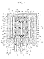
- the apparatus for producing trichlorosilane of the present embodiment includes a reaction vessel 1 in which a supply gas containing silicon tetrachloride and hydrogen is supplied to an internal reaction passageway to produce a reaction product gas containing trichlorosilane and hydrogen chloride; a heating mechanism 2 disposed in the periphery of the reaction vessel 1 for heating the reaction vessel 1 from the outside; a gas supply pipe 3 for supplying the supply gas in the reaction vessel 1; a plurality of gas discharge pipes 4 for discharging the reaction product gas from the reaction vessel 1 to the outside; a heat insulating material 5 disposed so as to cover the periphery of the reaction vessel 1 and the heating mechanism 2; a storage container 6 for storing the reaction vessel 1, the heating mechanism 2 and the heat insulating material 5; and an argon supplying mechanism 7 for supplying argon (Ar) in the storage container 6.
- a reaction vessel 1 in which a supply gas containing silicon tetrachloride and hydrogen is supplied to an internal reaction passageway
- the reaction passageway in the reaction vessel 1 includes a supply side passageway F1 which is connected to the gas supply pipe 3 at a central portion of the reaction vessel 1 and flows the supply gas toward the outside while meandering up and down in the reaction vessel 1, a return passageway F2 which is connected to a downstream end of the supply side passageway F1 and which returns the generated reaction product gas to the central portion of the reaction vessel 1, and a discharge side passageway F3 which is disposed so as to be connected to the downstream end of the return passageway F2 and to adjoin the supply side passageway F1 disposed in the central portion of the reaction vessel 1.
- the reaction vessel 1 is provided with cylindrical first to sixth reaction tubular walls 9a to 9f which have different inner diameters and are concentrically disposed in order from the inside; a first upper circular plate 21 for supporting the tops of the first to third reaction tubular walls 9a to 9c; a second upper circular plate 22 for supporting the tops of the fourth to sixth reaction tubular walls 9d to 9f; a first lower circular plate 23 for supporting the bottoms of the first to fifth reaction tubular walls 9a to 9e; a second lower circular plate 24 for supporting the bottom of the sixth reaction tubular wall 9f; and a first spacer member 25 and a second tubular spacer member 26 for supporting the first lower circular plate 23 on the second lower circular plate 24, the spacer members 25 and 26 having the same diameter and center axis as the first reaction tubular wall 9a and the second reaction tubular wall 9b respectively.
- the first to sixth reaction tubular walls 9a to 9f partition a majority of the internal space of the reaction vessel 1 into a central columnar small space 11 a and a plurality of tubular small spaces 11b to 11f in the periphery thereof.
- the first upper circular plate 21 has a diameter smaller than the second upper circular plate 22 and is provided below the second upper circular plate 22 with a predetermined space therebetween.
- a horizontal small space 30a is formed between both of these upper circular plates 21 and 22.
- the first lower circular plate 23 has a diameter smaller than the second lower circular plate 24 and is disposed above the second lower circular plate 24 interposing the first tubular spacer member 25 and the second tubular spacer member 26 so that there is a predetermined space provided therebetween.
- a horizontal small space 30b is formed between both of these lower circular plates 23 and 24.
- a first central hole 23a and a second central hole 24a are formed in the first lower circular plate 23 and the second lower circular plate 24 respectively.
- the small space 11a on the inside of the first reaction tubular wall 9a is in communication with the first tubular spacer member 25 and an after-mentioned supply connection pipe 13 via these first central hole 23a and second central hole 24a.
- a third central hole 21 is formed in the first upper circular plate 21 and the small space 11 a inside the first reaction tubular wall 9a is in communication with this third central hole 21 a.
- This small space 11a is in a communicative state with the horizontal small space 30a between both of the upper circular plates 21 and 22.
- a plurality of first through-holes 23b are formed in the circumferential direction on the outer circumference side of the first central hole 23a and a plurality of second through-holes 23c are formed in the circumferential direction more on the outer circumference side than these first through-holes 23b in the first lower circular plate 23.
- a plurality of third through-holes 24b are formed in the circumferential direction on the outer circumference side of the second central hole 24a in the second lower circular plate 24.
- a plurality of flow through-holes 10 are formed in the circumferential direction in upper portions of the second reaction tubular wall 9b and the fifth reaction tubular wall 9e. Also, a plurality of flow through-holes 10 are formed in the circumferential direction in a lower portion of the fourth reaction tubular wall 9d.
- the gas supply pipe 3 and gas discharge pipe 4 are in communication with a supply hole 6a and a discharge hole 6b formed in the bottom of the storage container 6 respectively, while the top ends thereof are fixed to the bottom of the storage container 6.
- a supply connection pipe 13 is disposed in a central portion of the storage container 6 by penetrating the heat insulating material 5 in the bottom of this storage container and, as shown in Figs. 1 and 3 , two tubular bodies 14A and 14B which penetrate the heat insulating material 5 are disposed in concentricity with this supply connection pipe 13. Between these tubular bodies 14A and 14B is formed a tubular discharge connection passageway 32. Also, the upper end openings of the supply hole 6a and the discharge hole 6b are in communication with the lower end openings of the supply connection pipe 13 and the discharge connection passageway 32 respectively.
- the supply connection pipe 13 supports a central lower surface of the second lower circular plate 24 on the upper end thereof and the upper end opening of the supply connection pipe 13 is in communication with the second central hole 24a.
- the outside tubular body 14A is formed longer than the inside tubular body 14B.
- An outer end portion of the second lower circular plate 24 is placed on top of this outside tubular body 14A and a horizontal passageway 33 is formed below this second lower circular plate 24. With such constitution, the upper end opening of the discharge connection passageway 32 communicates with the third through-hole 24b via this horizontal passageway 33.
- восем ⁇ of the gas discharge pipes 4 are disposed at equal intervals in the circumferential direction of the discharge connection passageway 32.
- a supply source (not shown) of the supply gas is connected to the gas supply pipe 3.
- a discharge pump may be connected to the gas discharge pipe 4.
- the first to sixth reaction tubular walls 9a to 9f, the first upper circular plate 21, the second upper circular plate 22, the first lower circular plate 23, the second lower circular plate 24, the first tubular spacer member 25, the second tubular spacer member 26, and the like are formed of carbon and the surface of the carbon is coated with silicon carbide.
- the storage container 6 is constituted of a tubular wall 35, and a bottom plate 36 and a ceiling plate 37 which block both ends thereof, and is made of stainless steel.
- the heating mechanism 2 is provided with a heater 15, which is a heating element, in the periphery of the reaction vessel 1 so as to enclose the reaction vessel 1 and with an electrode 16, which is connected to the bottom of the heater 15 and is for flowing an electric current to the heater 15.
- This electrode 16 is connected to a power supply (not shown).
- the heater 15 is formed of carbon.
- the heating mechanism 2 carries out heating control so that the temperature inside the reaction vessel 1 becomes a temperature in the range from 800 to 1,400°C. If the temperature inside the reaction vessel 1 is set to 1,200°C or higher, the conversion ratio is improved. Also, disilanes may be introduced to recover silanes.
- the heat insulating material 5 is formed of, for example, carbon, and is fixed to the inner wall surface of the tubular wall 35, the upper surface of the bottom plate 36, and the lower surface of the ceiling plate 37 of the storage container 6 so as to be pasted inside the storage container 6.
- a temperature sensor S which protrudes into the outermost small space 11 f in the reaction passageways F 1 to F3 is fixed to the lower surface of the second upper circular plate 2. The temperature is controlled by the heating mechanism 2 while the temperature is measured by this temperature sensor S.
- the argon supply mechanism 7 is provided with an argon supply pipe 17, the tip end thereof protruding into the storage container 6 by penetrating the bottom of the storage container 6 and the heat insulating material 5, and with an argon supply source 18 which is connected to the argon supply pipe 17.
- This argon supply mechanism 7 carries out argon supply control so that inside of the storage container becomes a predetermined pressurized state.
- a container pump (not shown) for carrying out replacement of the inside atmosphere or argon exhaustion is connected to the top of the storage container 6.
- a supply gas introduced from the gas supply pipe 3 via the supply connection pipe 13 flows, via the inside space of the first tubular spacer member 25, in an upper direction in the small space 11 a inside the first reaction tubular wall 9a.
- the supply gas flows in a downward direction in the outside tubular small space 11d between the third reaction tubular wall 9c and the fourth reaction tubular wall 9d.
- the supply gas moves to the outer tubular small space 11e between the fourth reaction tubular wall 9d and the fifth reaction wall 9e and flows in an upward direction.
- the supply gas moves from the flow through-holes 10 of the fifth reaction tubular wall 9e to the outermost small space 11f between the fifth reaction tubular wall 9e and the sixth reaction tubular wall 9f and flows in a downward direction.
- the passageway formed from the inside space of the first tubular spacer member 25, the small space 11a inside the first reaction tubular wall 9a, the horizontal small space 30a between the upper circular plate 21 and the upper circular plate 22, the three tubular small spaces 11d to 11f formed by the third reaction tubular wall 9c to the sixth reaction tubular wall 9f, and the flow through-holes which communicate the tubular small spaces 11d to 11f constitute the supply side passageway F1.
- the supply gas is converted to the reaction product gas by being heated during flowing.
- the supply gas supplied to the small space 11a inside the first reaction tubular wall 9a becomes a reaction product gas by reaction while being heated and sequentially flowing to the outside via a plurality of flow through-holes 10, and the like.
- the flow direction of the gas repetitively changes between the upward direction and the downward direction.
- the flow direction of the gas is indicated by arrows.
- the produced reaction product gas returns from the small space 11f between the fifth reaction tubular wall 9e and the sixth reaction tubular wall 9f to the central portion of the reaction vessel 1 by passing the horizontal small space 30b between the first lower circular plate 23 and the second lower circular plate 24.
- the small space 30b between the first lower circular plate 23 and the second lower circular plate 24 constitutes the return passageway F2.
- the reaction product gas is introduced into the small space 11c between the second reaction tubular wall 9b and the third reaction tubular wall 9c via the second through-hole 23c in the first lower circular plate 23, and flows in an upward direction.
- the reaction product gas flows into the small space 11b between the first reaction tubular wall 9a and the second reaction tubular wall 9b via the flow through-holes 10 in the second reaction tubular wall 9b, and flows in a downward direction.
- heat exchange is carried out, via the first reaction tubular wall 9a, between the reaction product gas and the supply gas flowing in the adjoining small space 11a inside the first reaction tubular wall 9a.
- the discharge side passageway F3 is constituted from both of the small spaces 11c between the second reaction tubular wall 9b and the third reaction tubular wall 9c, and 11b between the first reaction tubular wall 9a and the second reaction tubular wall 9b, respectively, and the communication through-holes 10 which communicate these small spaces 11c and 11b.
- reaction product gas flows through the first through-hole 23b in the first lower circular plate 23, interstitial space between the first tubular spacer member 25 and the second tubular spacer member 26, the third through-hole 24b in the second lower circular plate 24, the horizontal passageway 33, the discharge connection passageway 32, and the exhaust hole 6b in order, and is discharged to the outside from a plurality of the gas discharge pipes 4,
- the supply gas flows from the central portion of the reaction vessel 1 toward the outside while meandering (zigzagging) up and down and while being heated, and the supply gas is converted to the reaction product gas.
- the reaction product gas returns to the central portion of the reaction vessel 1 through the return passageway F2
- the reaction product gas flows in the discharge side passageway F3 adjoining the supply side passageway F1.
- the supply gas is preheated by heat exchange being carried out between the supply gas flowing in the supply side passageway F1 and the reaction product gas in a high-temperature state flowing in the discharge side passageway F3.
- this apparatus for producing trichlorosilane has a structure in which the reaction product gas in a high-temperature state is returned through the return passageway F2 to the discharge side passageway F3 adjoining the supply side passageway F1. heat exchange of the reaction product gas maintained in a high-temperature state with the supply gas can be conducted before discharge from the reaction vessel 1 and thus the supply gas can be efficiently preheated. Also, since a heat exchange mechanism is disposed in the reaction vessel 1, it is not necessary to separately dispose a heat exchange mechanism outside the reaction vessel and thus the size of the entire apparatus and the cost of the apparatus can be reduced.
- reaction vessel 1 is formed of carbon coated with silicon carbide (SiC), it is possible to set to a higher temperature compared to the case where the reaction vessel is formed of a pure carbon material. Thus, heat exchange with a higher temperature reaction product gas can be conducted and thus a high preheating effect can be obtained. Also, the production of impurities such as methane, methylchlorosilane, silicon carbide, and the like by the reaction of carbon with hydrogen, chlorosilane and hydrogen chloride (HCl) in the supply gas and the reaction product gas can be prevented and thus a highly pure trichlorosilane can be obtained.
- SiC silicon carbide
- the second upper circular plate 22 disposed on the upper end of the reaction tubular walls 9d to 9f on the outside is in a state of contacting the heat insulating material 5.
- the thermal expansion force of the reaction tubular walls 9d to 9f directly acts on the heat insulating material 5.
- This heat insulating material 5 is made to have cushioning property for absorbing the thermal expansion of the tubular walls.
- a clearance may be disposed between the heat insulating material 5 and the second upper circular plate 22.
- argon is supplied to the storage container 6 by the argon supplying mechanism 7, leakage of the supply gas and the reaction product gas from the reaction vessel 1 can be prevented by the periphery of the reaction vessel being in a pressurized state by argon. Thus, it is possible to prevent reaction of the supply gas and the reaction product gas which have leaked from the reaction vessel 1 with carbon used in the heating mechanism 2 and the like outside the reaction vessel 1.
- reaction tubular walls 9a to 9f While six first to sixth reaction tubular walls 9a to 9f were used in the above embodiments, a number of reaction tubular walls other than six may be used. When the number of reaction tubular walls is large, whereas the energy efficiency increases because of the increased heat transfer area, the heating efficiency decreases since it becomes difficult to transfer the radiant heat from the heating mechanism to the inside. Thus, an appropriate number of reaction tubular walls are disposed according to gas flow amount and the size of the entire apparatus.
- a cooling mechanism may be added by forming a refrigerant passageway for the flowing of a refrigerant such as water inside the wall of the storage container 5.
- the flow through-holes 10 in both reaction tubular walls which form cylindrical surfaces between the walls may be formed in not only up and down positions but in the circumferential direction so as to be dislocated with each other. In this situation, the passageway between the flow through-holes 10 can be made longer. Also, they do not have to be through-holes and may be flow penetration sections by notches formed in the upper end portion or the lower end portion of the reaction tubular walls.
- the discharge connection passageway 32 is formed between a pair of pipe bodies 14A and 14B.
- one pipe body may be disposed so as to surround a periphery of the supply connection pipe 13, forming the discharge connection passageway therebetween.
- a discharge pipe may also be formed to surround a periphery of the gas supply pipe 3 in a double pipe arrangement.
- the position of the gas supply pipe 3 and the gas discharge pipe 4 may be disposed oppositely and by a similar apparatus structure, the gas flow may be opposite by exchanging the entrance and the exit of the gas.
- the apparatus for producing trichlorosilane of the present invention it is possible to efficiently preheat the supply gas by heat exchange between the supply gas and the reaction product gas maintained in a high-temperature state. Also, the entire size of the apparatus and the cost of the apparatus can be reduced since a heat exchange mechanism is disposed in the reaction vessel. Therefore, it is possible to obtain a high trichlorosilane-conversion ratio with good heating efficiency using a small and low cost apparatus.
Landscapes
- Chemical & Material Sciences (AREA)
- Organic Chemistry (AREA)
- Chemical Kinetics & Catalysis (AREA)
- Inorganic Chemistry (AREA)
- Silicon Compounds (AREA)
Claims (5)
- Appareil de production de trichlorosilane, comprenant :une enceinte de réaction (1) dans lequel un gaz d'alimentation contenant du tétrachlorure de silicium et de l'hydrogène est fourni à une voie de passage de réaction interne pour produire un gaz de produit de réaction contenant du trichlorosilane et du chlorure d'hydrogène, l'enceinte de réaction (1) comprenant une pluralité de parois tubulaires de réaction cylindriques (9a, 9b, 9c, 9d, 9e, 9f) présentant des diamètres intérieurs différents qui sont disposées concentriquement et constituent un espace colonnaire central (11a) et une pluralité d'espaces tubulaires (11b, 11c, 11d, 11e, 11f) à la périphérie de celui-ci ;un mécanisme de chauffage (2) qui chauffe l'intérieur de l'enceinte de réaction (1) ;une section d'alimentation de gaz (3) qui fournit le gaz d'alimentation dans l'enceinte de réaction (1) ; etune section d'évacuation de gaz (4) qui évacue vers l'extérieur le gaz de produit de réaction de l'enceinte de réaction (1), dans lequella voie de passage de réaction comprend :une voie de passage de côté d'alimentation (F1) qui est reliée à la section d'alimentation de gaz (3) au niveau de l'espace colonnaire (11a) de l'enceinte de réaction (1) et fait s'écouler le gaz d'alimentation vers l'espace tubulaire le plus extérieur (11f) en serpentant dans l'enceinte de réaction (1) ;une voie de passage de retour (F2) qui est reliée à une extrémité aval de la voie de passage de côté d'alimentation (F1) et s'étend vers la portion centrale de l'enceinte de réaction (1) ; etune voie de passage de côté d'évacuation (F3) qui est disposée de manière à être reliée à une extrémité aval de la voie de passage de retour (F2) et à jouxter la voie de passage de côté d'alimentation au niveau de l'espace tubulaire le plus intérieur (11b), la voie de passage de côté d'évacuation (F3) étant reliée à la section d'évacuation de gaz (4).
- Appareil de production de trichlorosilane selon la revendication 1, comprenant : une pluralité de sections d'évacuation de gaz (4), dans lequel la pluralité de sections d'évacuation de gaz (4) sont reliées à une extrémité aval de la voie de passage de côté de décharge (F3).
- Appareil de production de trichlorosilane selon la revendication 1 ou 2, dans lequel un organe constituant l'enceinte de réaction (1) est constitué de carbone.
- Appareil de production de trichlorosilane selon la revendication 3, dans lequel la surface du carbone est revêtue de carbure de silicium.
- Appareil de production de trichlorosilane selon l'une quelconque des revendications 1 à 4, comprenant : un récipient de stockage (6) qui renferme l'enceinte de réaction (1) et le mécanisme de chauffage (2), et un mécanisme d'alimentation en argon (7) qui fournit de l'argon dans le récipient de stockage (6).
Applications Claiming Priority (3)
| Application Number | Priority Date | Filing Date | Title |
|---|---|---|---|
| JP2006297035 | 2006-10-31 | ||
| JP2007259446A JP5205906B2 (ja) | 2006-10-31 | 2007-10-03 | トリクロロシラン製造装置 |
| PCT/JP2007/070725 WO2008053760A1 (fr) | 2006-10-31 | 2007-10-24 | Appareil de production de trichlorosilane |
Publications (3)
| Publication Number | Publication Date |
|---|---|
| EP2003092A1 EP2003092A1 (fr) | 2008-12-17 |
| EP2003092A4 EP2003092A4 (fr) | 2011-01-19 |
| EP2003092B1 true EP2003092B1 (fr) | 2015-08-19 |
Family
ID=39344102
Family Applications (1)
| Application Number | Title | Priority Date | Filing Date |
|---|---|---|---|
| EP07830459.9A Active EP2003092B1 (fr) | 2006-10-31 | 2007-10-24 | Appareil de production de trichlorosilane |
Country Status (5)
| Country | Link |
|---|---|
| US (1) | US9493359B2 (fr) |
| EP (1) | EP2003092B1 (fr) |
| JP (1) | JP5205906B2 (fr) |
| CN (1) | CN101421189B (fr) |
| WO (1) | WO2008053760A1 (fr) |
Families Citing this family (6)
| Publication number | Priority date | Publication date | Assignee | Title |
|---|---|---|---|---|
| JP5428146B2 (ja) * | 2006-10-31 | 2014-02-26 | 三菱マテリアル株式会社 | トリクロロシラン製造装置 |
| WO2010107262A2 (fr) * | 2009-03-20 | 2010-09-23 | 주식회사수성기술 | Conteneur hermétique pour réaction de conversion thermique |
| CN102190305B (zh) * | 2010-03-15 | 2014-10-29 | 三菱综合材料株式会社 | 三氯硅烷制造装置 |
| DE102011002749A1 (de) * | 2011-01-17 | 2012-07-19 | Wacker Chemie Ag | Verfahren und Vorrichtung zur Konvertierung von Siliciumtetrachlorid in Trichlorsilan |
| US9222733B2 (en) | 2011-02-03 | 2015-12-29 | Memc Electronic Materials S.P.A. | Reactor apparatus and methods for reacting compounds |
| JP5974857B2 (ja) * | 2011-11-28 | 2016-08-23 | 三菱マテリアル株式会社 | トリクロロシラン製造装置 |
Family Cites Families (16)
| Publication number | Priority date | Publication date | Assignee | Title |
|---|---|---|---|---|
| FR656254A (fr) * | 1926-06-22 | 1929-05-06 | Appareil pour l'exécution de réactions entre fluides, s'accomplissant à température élevée | |
| US2145084A (en) * | 1936-02-12 | 1939-01-24 | Hersey John Cronin | Heat exchange apparatus |
| US2644744A (en) * | 1951-02-26 | 1953-07-07 | Universal Oil Prod Co | Reactor for high-temperature cracking |
| DE3024320A1 (de) | 1980-06-27 | 1982-04-01 | Wacker-Chemitronic Gesellschaft für Elektronik-Grundstoffe mbH, 8263 Burghausen | Vorrichtung zur hochtemperaturbehandlung von gasen |
| JPS57156318A (en) * | 1981-03-16 | 1982-09-27 | Koujiyundo Silicon Kk | Production of trichlorosilane |
| US4737348A (en) * | 1982-06-22 | 1988-04-12 | Harry Levin | Apparatus for making molten silicon |
| US4668493A (en) * | 1982-06-22 | 1987-05-26 | Harry Levin | Process for making silicon |
| JPS60122714A (ja) | 1983-12-06 | 1985-07-01 | Denki Kagaku Kogyo Kk | 四塩化珪素の製造方法及びその製造装置 |
| JPS6221706A (ja) | 1985-07-22 | 1987-01-30 | Nippon Steel Corp | トリクロルシランを介する珪素または珪素化合物の循環的製造方法 |
| JPH0649569B2 (ja) | 1985-11-25 | 1994-06-29 | 高純度シリコン株式会社 | トリクロルシランの製造方法およびその装置 |
| US5906799A (en) | 1992-06-01 | 1999-05-25 | Hemlock Semiconductor Corporation | Chlorosilane and hydrogen reactor |
| JPH08157073A (ja) * | 1994-12-06 | 1996-06-18 | Nippon Steel Corp | 飛散粉塵の集塵機能を有するホッパー |
| JP3529070B2 (ja) | 1995-12-01 | 2004-05-24 | 電気化学工業株式会社 | カーボン製反応容器 |
| US20040173597A1 (en) | 2003-03-03 | 2004-09-09 | Manoj Agrawal | Apparatus for contacting gases at high temperature |
| DE102005005044A1 (de) | 2005-02-03 | 2006-08-10 | Consortium für elektrochemische Industrie GmbH | Verfahren zur Herstellung von Trichlorsilan mittels thermischer Hydrierung von Siliciumtetrachlorid |
| DE102005046703A1 (de) | 2005-09-29 | 2007-04-05 | Wacker Chemie Ag | Verfahren und Vorrichtung zur Hydrierung von Chlorsilanen |
-
2007
- 2007-10-03 JP JP2007259446A patent/JP5205906B2/ja not_active Expired - Fee Related
- 2007-10-24 CN CN2007800127053A patent/CN101421189B/zh active Active
- 2007-10-24 US US12/226,204 patent/US9493359B2/en active Active
- 2007-10-24 WO PCT/JP2007/070725 patent/WO2008053760A1/fr active Application Filing
- 2007-10-24 EP EP07830459.9A patent/EP2003092B1/fr active Active
Also Published As
| Publication number | Publication date |
|---|---|
| JP2008133169A (ja) | 2008-06-12 |
| WO2008053760A1 (fr) | 2008-05-08 |
| US9493359B2 (en) | 2016-11-15 |
| EP2003092A1 (fr) | 2008-12-17 |
| CN101421189A (zh) | 2009-04-29 |
| US20090269259A1 (en) | 2009-10-29 |
| EP2003092A4 (fr) | 2011-01-19 |
| JP5205906B2 (ja) | 2013-06-05 |
| CN101421189B (zh) | 2011-09-28 |
Similar Documents
| Publication | Publication Date | Title |
|---|---|---|
| EP2000434B1 (fr) | Appareil de production de trichlorosilane | |
| US7998428B2 (en) | Apparatus for producing trichlorosilane | |
| US9416014B2 (en) | Method for producing trichlorosilane | |
| EP2003092B1 (fr) | Appareil de production de trichlorosilane | |
| CN103328381B (zh) | 用于将四氯化硅转化为三氯硅烷的方法及装置 | |
| JP5160181B2 (ja) | トリクロロシラン製造装置 | |
| US9468042B2 (en) | Apparatus for producing trichlorosilane | |
| JP5083004B2 (ja) | トリクロロシラン製造装置 | |
| US8372346B2 (en) | Apparatus for producing trichlorosilane | |
| JP2011157223A (ja) | トリクロロシラン製造装置 |
Legal Events
| Date | Code | Title | Description |
|---|---|---|---|
| PUAI | Public reference made under article 153(3) epc to a published international application that has entered the european phase |
Free format text: ORIGINAL CODE: 0009012 |
|
| 17P | Request for examination filed |
Effective date: 20081008 |
|
| AK | Designated contracting states |
Kind code of ref document: A1 Designated state(s): DE IT |
|
| RBV | Designated contracting states (corrected) |
Designated state(s): DE IT |
|
| A4 | Supplementary search report drawn up and despatched |
Effective date: 20101221 |
|
| DAX | Request for extension of the european patent (deleted) | ||
| 17Q | First examination report despatched |
Effective date: 20111020 |
|
| GRAP | Despatch of communication of intention to grant a patent |
Free format text: ORIGINAL CODE: EPIDOSNIGR1 |
|
| RIC1 | Information provided on ipc code assigned before grant |
Ipc: B01J 19/24 20060101ALI20150226BHEP Ipc: C01B 33/107 20060101AFI20150226BHEP Ipc: B01J 19/02 20060101ALI20150226BHEP Ipc: B01J 12/00 20060101ALI20150226BHEP |
|
| INTG | Intention to grant announced |
Effective date: 20150317 |
|
| GRAS | Grant fee paid |
Free format text: ORIGINAL CODE: EPIDOSNIGR3 |
|
| GRAA | (expected) grant |
Free format text: ORIGINAL CODE: 0009210 |
|
| AK | Designated contracting states |
Kind code of ref document: B1 Designated state(s): DE IT |
|
| REG | Reference to a national code |
Ref country code: DE Ref legal event code: R096 Ref document number: 602007042699 Country of ref document: DE |
|
| PG25 | Lapsed in a contracting state [announced via postgrant information from national office to epo] |
Ref country code: IT Free format text: LAPSE BECAUSE OF FAILURE TO SUBMIT A TRANSLATION OF THE DESCRIPTION OR TO PAY THE FEE WITHIN THE PRESCRIBED TIME-LIMIT Effective date: 20150819 |
|
| REG | Reference to a national code |
Ref country code: DE Ref legal event code: R097 Ref document number: 602007042699 Country of ref document: DE |
|
| PLBE | No opposition filed within time limit |
Free format text: ORIGINAL CODE: 0009261 |
|
| STAA | Information on the status of an ep patent application or granted ep patent |
Free format text: STATUS: NO OPPOSITION FILED WITHIN TIME LIMIT |
|
| 26N | No opposition filed |
Effective date: 20160520 |
|
| REG | Reference to a national code |
Ref country code: DE Ref legal event code: R081 Ref document number: 602007042699 Country of ref document: DE Owner name: HIGH-PURITY SILICON CORP., YOKKAICHI-SHI, JP Free format text: FORMER OWNER: MITSUBISHI MATERIALS CORP., TOKYO, JP |
|
| PGFP | Annual fee paid to national office [announced via postgrant information from national office to epo] |
Ref country code: DE Payment date: 20231020 Year of fee payment: 17 |