EP2003011B1 - Rail adjustment system for a motor vehicle seat - Google Patents
Rail adjustment system for a motor vehicle seat Download PDFInfo
- Publication number
- EP2003011B1 EP2003011B1 EP08001471.5A EP08001471A EP2003011B1 EP 2003011 B1 EP2003011 B1 EP 2003011B1 EP 08001471 A EP08001471 A EP 08001471A EP 2003011 B1 EP2003011 B1 EP 2003011B1
- Authority
- EP
- European Patent Office
- Prior art keywords
- support
- adjustment system
- rail
- guide channel
- retaining element
- Prior art date
- Legal status (The legal status is an assumption and is not a legal conclusion. Google has not performed a legal analysis and makes no representation as to the accuracy of the status listed.)
- Active
Links
- 238000005253 cladding Methods 0.000 description 5
- 238000011161 development Methods 0.000 description 3
- 230000018109 developmental process Effects 0.000 description 3
- 238000006073 displacement reaction Methods 0.000 description 2
- 238000002347 injection Methods 0.000 description 2
- 239000007924 injection Substances 0.000 description 2
- 230000006641 stabilisation Effects 0.000 description 2
- 238000011105 stabilization Methods 0.000 description 2
- 238000005452 bending Methods 0.000 description 1
- 230000015572 biosynthetic process Effects 0.000 description 1
- 238000005516 engineering process Methods 0.000 description 1
- 238000009434 installation Methods 0.000 description 1
- 238000004519 manufacturing process Methods 0.000 description 1
Images


Classifications
-
- B—PERFORMING OPERATIONS; TRANSPORTING
- B60—VEHICLES IN GENERAL
- B60N—SEATS SPECIALLY ADAPTED FOR VEHICLES; VEHICLE PASSENGER ACCOMMODATION NOT OTHERWISE PROVIDED FOR
- B60N2/00—Seats specially adapted for vehicles; Arrangement or mounting of seats in vehicles
- B60N2/02—Seats specially adapted for vehicles; Arrangement or mounting of seats in vehicles the seat or part thereof being movable, e.g. adjustable
- B60N2/04—Seats specially adapted for vehicles; Arrangement or mounting of seats in vehicles the seat or part thereof being movable, e.g. adjustable the whole seat being movable
- B60N2/06—Seats specially adapted for vehicles; Arrangement or mounting of seats in vehicles the seat or part thereof being movable, e.g. adjustable the whole seat being movable slidable
- B60N2/067—Seats specially adapted for vehicles; Arrangement or mounting of seats in vehicles the seat or part thereof being movable, e.g. adjustable the whole seat being movable slidable by linear actuators, e.g. linear screw mechanisms
-
- B—PERFORMING OPERATIONS; TRANSPORTING
- B60—VEHICLES IN GENERAL
- B60N—SEATS SPECIALLY ADAPTED FOR VEHICLES; VEHICLE PASSENGER ACCOMMODATION NOT OTHERWISE PROVIDED FOR
- B60N2/00—Seats specially adapted for vehicles; Arrangement or mounting of seats in vehicles
- B60N2/02—Seats specially adapted for vehicles; Arrangement or mounting of seats in vehicles the seat or part thereof being movable, e.g. adjustable
- B60N2/0224—Non-manual adjustments, e.g. with electrical operation
- B60N2/02246—Electric motors therefor
- B60N2/02253—Electric motors therefor characterised by the transmission between the electric motor and the seat or seat parts
-
- B—PERFORMING OPERATIONS; TRANSPORTING
- B60—VEHICLES IN GENERAL
- B60N—SEATS SPECIALLY ADAPTED FOR VEHICLES; VEHICLE PASSENGER ACCOMMODATION NOT OTHERWISE PROVIDED FOR
- B60N2/00—Seats specially adapted for vehicles; Arrangement or mounting of seats in vehicles
- B60N2/02—Seats specially adapted for vehicles; Arrangement or mounting of seats in vehicles the seat or part thereof being movable, e.g. adjustable
- B60N2/0224—Non-manual adjustments, e.g. with electrical operation
- B60N2/02246—Electric motors therefor
- B60N2/02258—Electric motors therefor characterised by the mounting of the electric motor for adjusting the seat
-
- B—PERFORMING OPERATIONS; TRANSPORTING
- B60—VEHICLES IN GENERAL
- B60N—SEATS SPECIALLY ADAPTED FOR VEHICLES; VEHICLE PASSENGER ACCOMMODATION NOT OTHERWISE PROVIDED FOR
- B60N2/00—Seats specially adapted for vehicles; Arrangement or mounting of seats in vehicles
- B60N2/02—Seats specially adapted for vehicles; Arrangement or mounting of seats in vehicles the seat or part thereof being movable, e.g. adjustable
- B60N2/04—Seats specially adapted for vehicles; Arrangement or mounting of seats in vehicles the seat or part thereof being movable, e.g. adjustable the whole seat being movable
- B60N2/06—Seats specially adapted for vehicles; Arrangement or mounting of seats in vehicles the seat or part thereof being movable, e.g. adjustable the whole seat being movable slidable
- B60N2/07—Slide construction
- B60N2/0702—Slide construction characterised by its cross-section
- B60N2/0705—Slide construction characterised by its cross-section omega-shaped
Definitions
- the invention relates to a rail adjustment system for a motor vehicle seat having the features of the preamble of claim 1.
- One from the DE 198 15 283 C2 Known Schienenverstellsystem comprises a drive motor which is centrally mounted between two rails of a pair of seat rails on a holding plate connected to the upper rails.
- the drive motor is coupled on both sides by means of drive shafts, which can also be designed as flexible shafts, with a spindle nut mounted in a spindle drive. This cooperates with a arranged between a longitudinally displaceable upper rail and a stationary or bottom-fixed lower rail threaded spindle for rail longitudinal adjustment.
- a rotational movement of the drive motor is thus implemented via the drive shafts and the spindle gear in a longitudinal displacement of the respective upper rail against the corresponding lower rail of the rail pair.
- the flexible drive shaft which has a rotating flexible core and a surrounding this likewise flexible cladding tube, can be guided to their positional stabilization in an additional tube.
- the flexible shaft can also be stabilized by the fact that according to DE 102 00 985 B4 in the flexible cladding tube between the ends of support points for the rotating soul are integrated.
- a rail adjustment system of the type mentioned is proposed, wherein the flexible drive shaft leading support elements are formed as issued from the holding element clamping straps.
- results in the holding element by issuing the clamping plates conditionally on the opposite side a clamping strap a support gap.
- the issued clamping straps are each arranged opposite each other.
- the invention has for its object to provide an improved Schienenverstellsystem of the type mentioned.
- a suitable guidance of a flexible drive shaft should be provided at the same time as low as possible noise.
- a guide and / or receiving channel for the drive shaft is integrated in the running between the rails of the rail pair holding element.
- the guide channel has a number of support elements and support gaps and is bounded by a first support row and a second support row, wherein the two support rows are spaced from each other. The distance corresponds to at least the outer diameter of the flexible drive shaft. If the two support rows lie opposite each other in the z-direction with respect to the usual vehicle coordinate system, the guide channel is preferably delimited by at least two spaced-apart side walls at least the outer diameter of the drive shaft in the x-direction (rail or vehicle longitudinal direction).
- the two support rows each have alternately successively arranged support elements and support gaps.
- the or each support element spans an opposite support gap at least partially.
- the support rows are offset from each other such that in each case a support element a opposite support gap at least partially, but expediently completely overstretched.
- the support elements are suitably designed as web-like structural sections of the holding element. At the or each support elements, a local support point is formed. The respective position of the individual support points on the corresponding support element are chosen such that within the two support rows each two support points are arranged obliquely opposite each other.
- the holding element is therefore expediently made of plastic and preferably as an injection molded part.
- the holding element in this case suitably has a lattice structure flanking the guide channel on both sides. In this way, material-saving a stable, bending and torsion-resistant retaining element can be made.
- Glasgownd worne retaining tabs of the retaining element allow their attachment to the spaced opposite rails, especially at the top rails.
- the holding element expediently has a recess in which the electric motor or drive motor of the spindle drive, which is also referred to below as the drive system, rests and can be fastened there.
- the recess is thereby introduced into the holding element to form a comparatively long carrier section and a comparatively short carrier section, wherein the guide channel extends within the comparatively long carrier section.
- the advantages achieved by the invention are in particular that a reliable guidance and storage of the drive shaft is ensured by the arrangement of a torsionally stiff, but otherwise flexible drive shaft in a guide channel arranged between the rails of a rail pair of a motor vehicle seat holding member or support member in a simple manner ,
- a spindle drive associated with such a drive system, in particular a spindle drive, noise developments are avoided or at least considerably reduced. This is of considerable importance in terms of comfort, especially since the drive system is usually positioned relatively close to the user under the corresponding vehicle seat and there under the seat.
- the comparatively long drive path from the spindle drive to the remote rail is bridged by the flexible drive shaft and reliably transmit the driving force of the spindle drive to the corresponding threaded spindle.
- the driving force on the rail close to the electric motor is then transmitted to the local threaded spindle via a comparatively short drive path.
- a short shaft journal is suitably sufficient.
- the guide channel within the holding element in the form of staggered rows of support alternately arranged one behind the other, suitably web-like support elements and supporting gaps, which are suitably formed in a designed as a plastic structural member holding element, a particularly reliable integrated motor and shaft bearings and wave guide are provided. This makes it possible, especially during initial assembly as well as for repair purposes, to assemble and disengage the flexible drive shaft in the guide channel, which is designed as a support structure, or out of it.
- the support and guide structure within the support member for the flexible drive shaft is practically pointwise feasible, i. the flexible drive shaft is supported along the guide channel on opposite sides in the region of the support elements at several local points.
- the supporting points in the form of dome-like elevations, which are suitably integrally formed on the support elements, are preferably positioned in such a way that these raised support structures lie opposite one another in pairs and are spatially arranged as close as possible to one another.
- the thus formed grid-like and consequently selective support structure of the correspondingly shaped support or guide channel for the flexible drive shaft thus enables their particularly simple installation in this specially designed guide channel. Due to the suitable position stabilization of the drive shaft the development of vibration noise is reliably prevented.
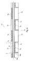
- FIGS. 1 and 2 show a Schienenverstellsystem 1 for a motor vehicle seat with a pair of rails whose spaced opposite and mutually parallel rails 2, 3 each comprise an upper rail 2a, 3a and a lower rail 2b and 3b respectively. With the upper rails 2a, 3a, a carrier part referred to below as a holding element 4 is connected.
- the upper rails 2a, 3a are longitudinally displaceable in the x-direction with respect to the vehicle-floor-fixed lower rails 2b and 3b.
- the holding element 4 thus extends in the y-direction, ie transversely to the rails 2, 3.
- a (not shown) vehicle seat or a corresponding seat frame is attached.
- the holding element 4 is an injection molded part made of plastic. It has on both ends retaining tabs 4a, 4b, by means of which the holding element 4 with the rails 2, 3 and there connected to the top rails 2a and 3a, for example, screwed or riveted.
- the holding element 4 has, in particular in a comparatively long carrier section a, a lattice-like support structure 5, which is referred to below as a lattice structure, with a multiplicity of grid bars 6 arranged in a square or diamond-shaped manner.
- a guide channel 7 is provided within this grid structure 5 of the support section a.
- the lattice structure 5 flanks the guide channel 7 on both sides and preferably symmetrically.
- the guide channel 7 extends from a decentralized recess 8 - the Fig. 2 is comparatively clearly visible - along the support section a to the remote, in the representations of the Fig. 1 and 2 front rail 3.
- a comparatively short support section b extends on the opposite side in turn, starting from the recess 8 to the next this, in the illustration upper rail 2.
- the recess serves to receive and fix an electric motor 9 of a drive system designed as a spindle drive ,
- the driving force of the electric motor 9 is on the one hand via a flexible drive shaft 10 to the electric motor 9 distant rail 3 and there transferred to a threaded spindle 11 ( Fig. 5 ).
- a flexible drive shaft 10 to the electric motor 9 distant rail 3 and there transferred to a threaded spindle 11 ( Fig. 5 ).
- the rotational movement of the drive motor 9 is thus transmitted via the flexible drive shaft 10 to a spindle gear 12 and from there to the threaded spindle 11, whereby the longitudinal adjustment of the upper rail 3a relative to the lower rail 3b is effected.
- the flexible drive shaft 10 is arranged within the guide channel 7 of the holding element 4.
- the Fig. 3 and 4 show the guide channel 7 for the flexible drive shaft 10 in a larger scale.
- this guide channel 7 is formed by cover-like retracted, web-like support structures or elements 7a on the one hand and window-like recessed support gaps 7b on the other.
- opposing top and bottom rows of support 14 and 15 are formed in the z-direction with support elements 7a and support gaps 7b arranged alternately one behind the other in the y-direction.
- the first support row 14 and the second support row 15 are offset from one another.
- a support element 7a of a support row 14, 15 faces a support gap 7b of the other support row 15 or 14.
- the web-like support elements 7a span at least approximately completely the respectively opposite support gap 7b.
- dome-like elevation are formed, forming the local support points 7c.
- the guide channel 7 is laterally limited by each other in the x-direction spaced opposite side walls 7d and 7e, which also extend along the comparatively long portion a of the support member 4.
- the clear width of the guide channel 7 is adapted to the thickness of the flexible drive shaft 10, ie the clear width of the guide channel is slightly larger than or equal to the outer diameter of the drive shaft 10th
- the flexible drive shaft 10 is supported at these support points 7c point or line.
- opposite support points 7c of the respective support elements 7a are slightly offset relative to one another in the y-direction.
- the flexible drive shaft 10, whose flexible torsionally rigid core 10a is covered by a likewise flexible cladding tube 10b is thus supported along the guide channel 7 at a plurality of support points or points, which are substantially by the raised Support points 7c, but in principle are formed by the respective support elements 7a.
- Fig. 5 illustrates, guided in the guide channel 7 drive shaft 10 is connected in the spindle gear 12 with a worm wheel 16 which meshes with a spindle nut 17 of the spindle gear 12.
- a rotational movement of the driven by the electric motor 9 drive shaft 10 is converted into a corresponding rotational movement of the spindle nut 17, which in turn meshes with the threaded spindle 11.
- the spindle gear 12 is fixedly connected to the respective upper rail 3a, while the threaded spindle 11 is fixedly connected to the lower rail 3b of the corresponding rail 3.
- retaining tabs 18 are provided on both sides of the threaded spindle 11 . These are provided with pivot bearings 19 in which the threaded spindle 11 rotatably rests.
Description
Die Erfindung betrifft ein Schienenverstellsystem für einen Kraftfahrzeugsitz mit den Merkmalen des Oberbegriffs von Anspruch 1.The invention relates to a rail adjustment system for a motor vehicle seat having the features of the preamble of claim 1.
Ein aus der
Die flexible Antriebswelle, die eine rotierende flexible Seele und ein dieses umschließendes ebenfalls flexibles Hüllrohr aufweist, kann zu deren Lagestabilisierung in einem zusätzlichen Rohr geführt sein. Alternativ kann die flexible Welle auch dadurch stabilisiert werden, dass gemäß der
In der
Während die Bereitstellung eines zusätzlichen Stützrohres für die flexible Antriebswelle einen erhöhten Teileaufwand bedeutet, ist eine flexible Antriebswelle, deren flexibles Hüllrohr mit Stützstellen für die rotierende Seele versehen ist, fertigungstechnisch aufwändig. Zudem neigen Schienenverstellsysteme, deren Spindelantriebe mit derartigen Antriebswellen ausgerüstet sind, zu unerwünschten Geräuschentwicklungen.While the provision of an additional support tube for the flexible drive shaft means increased parts costs, a flexible drive shaft whose flexible cladding tube is provided with support points for the rotating soul, manufacturing technology consuming. In addition, rail adjustment systems whose spindle drives are equipped with such drive shafts tend to undesirable noise developments.
Der Erfindung liegt die Aufgabe zugrunde, ein verbessertes Schienenverstellsystem der eingangs genannten Art anzugeben. Insbesondere soll eine geeignete Führung einer flexiblen Antriebswelle bei gleichzeitig möglichst geringer Geräuschentwicklung bereitgestellt werden.The invention has for its object to provide an improved Schienenverstellsystem of the type mentioned. In particular, a suitable guidance of a flexible drive shaft should be provided at the same time as low as possible noise.
Diese Aufgabe wird erfindungsgemäß durch die Merkmale des Anspruchs 1 gelöst. Dazu ist in das zwischen den Schienen des Schienenpaares verlaufende Halteelement ein Führungs- und/oder Aufnahmekanal für die Antriebswelle integriert. Der Führungskanal weist eine Anzahl von Stützelementen und Stützlücken auf und ist von einer ersten Stützreihe sowie einer zweiten Stützreihe begrenzt, wobei die beiden Stützreihen einander beabstandet gegenüberliegen. Der Abstand entspricht dabei mindestens dem Außendurchmesser der flexiblen Antriebswelle. Liegen sich die beiden Stützreihen - bezogen auf das übliche Fahrzeugkoordinatensystem - in z-Richtung einander gegenüber, so ist der Führungskanal vorzugsweise durch zwei wiederum im Abstand mindestens des Außendurchmessers der Antriebswelle in x-Richtung (Schienen- bzw. Fahrzeuglängsrichtung) einander gegenüberliegenden Seitenwänden begrenzt.This object is achieved by the features of claim 1. For this purpose, a guide and / or receiving channel for the drive shaft is integrated in the running between the rails of the rail pair holding element. The guide channel has a number of support elements and support gaps and is bounded by a first support row and a second support row, wherein the two support rows are spaced from each other. The distance corresponds to at least the outer diameter of the flexible drive shaft. If the two support rows lie opposite each other in the z-direction with respect to the usual vehicle coordinate system, the guide channel is preferably delimited by at least two spaced-apart side walls at least the outer diameter of the drive shaft in the x-direction (rail or vehicle longitudinal direction).
Die beiden Stützreihen weisen jeweils alternierend hintereinander angeordnete Stützelemente und Stützlücken auf. Dabei überspannt das oder jedes Stützelement eine gegenüberliegende Stützlücke zumindest teilweise. Insbesondere sind die Stützreihen derart gegeneinander versetzt, dass jeweils ein Stützelement eine gegenüberliegender Stützlücke zumindest teilweise, zweckmäßigerweise jedoch vollständig überspannt.The two support rows each have alternately successively arranged support elements and support gaps. In this case, the or each support element spans an opposite support gap at least partially. In particular, the support rows are offset from each other such that in each case a support element a opposite support gap at least partially, but expediently completely overstretched.
Die Stützelemente sind geeigneterweise als stegartige Strukturabschnitte des Halteelementes ausgebildet. An das oder jedes Stützelemente ist eine lokale Stützstelle angeformt. Die jeweilige Position der einzelnen Stützstellen am entsprechenden Stützelement sind derart gewählt, das innerhalb der beiden Stützreihen jeweils zwei Stützstellen einander schräg gegenüberliegend angeordnet sind.The support elements are suitably designed as web-like structural sections of the holding element. At the or each support elements, a local support point is formed. The respective position of the individual support points on the corresponding support element are chosen such that within the two support rows each two support points are arranged obliquely opposite each other.
Das Halteelement ist daher zweckmäßigerweise aus Kunststoff und vorzugsweise als Spritzgussteil gefertigt. Das Halteelement weist hierbei geeigneterweise eine den Führungskanal beidseitig flankierende Gitterstruktur auf. Auf diese Weise kann Material sparend ein stabiles, biege- und verwindungssteifes Halteelement gefertigt werden. Beidendseitige Haltelaschen des Halteelementes ermöglichen deren Befestigung an den einander beabstandet gegenüberliegenden Schienen, insbesondere an deren Oberschienen.The holding element is therefore expediently made of plastic and preferably as an injection molded part. The holding element in this case suitably has a lattice structure flanking the guide channel on both sides. In this way, material-saving a stable, bending and torsion-resistant retaining element can be made. Beidendseitige retaining tabs of the retaining element allow their attachment to the spaced opposite rails, especially at the top rails.
Das Halteelement weist zweckmäßigerweise eine Ausnehmung auf, in der der Elektromotor oder Antriebsmotor des nachfolgend auch als Antriebssystem bezeichneten Spindelantriebs einliegt und dort befestigt werden kann. Die Ausnehmung ist dabei unter Bildung eines vergleichsweise langen Trägerabschnitts und eines vergleichsweise kurzen Trägerabschnitts in das Halteelement eingebracht, wobei sich der Führungskanal innerhalb des vergleichsweise langen Trägerabschnitts erstreckt.The holding element expediently has a recess in which the electric motor or drive motor of the spindle drive, which is also referred to below as the drive system, rests and can be fastened there. The recess is thereby introduced into the holding element to form a comparatively long carrier section and a comparatively short carrier section, wherein the guide channel extends within the comparatively long carrier section.
Die mit der Erfindung erzielten Vorteile bestehen insbesondere darin, dass durch die Anordnung einer drehsteifen, jedoch ansonsten flexiblen Antriebswelle in einem Führungskanal eines zwischen den Schienen eines Schienenpaares eines Kraftfahrzeugsitzes angeordneten Halteelementes oder Trägerteils in einfacher Art und Weise eine zuverlässige Führung und Lagerung der Antriebswelle sichergestellt ist. Zudem sind mit einem solchen Antriebssystem, insbesondere einem Spindelantrieb, verbundene Geräuschentwicklungen vermieden oder zumindest erheblich reduziert. Dies ist hinsichtlich des Komforts von erheblicher Bedeutung, zumal das Antriebssystem üblicherweise relativ nah zur Benutzerperson unter dem entsprechenden Fahrzeugsitz und dort unter der Sitzfläche positioniert ist.The advantages achieved by the invention are in particular that a reliable guidance and storage of the drive shaft is ensured by the arrangement of a torsionally stiff, but otherwise flexible drive shaft in a guide channel arranged between the rails of a rail pair of a motor vehicle seat holding member or support member in a simple manner , In addition, associated with such a drive system, in particular a spindle drive, noise developments are avoided or at least considerably reduced. This is of considerable importance in terms of comfort, especially since the drive system is usually positioned relatively close to the user under the corresponding vehicle seat and there under the seat.
Infolge der bevorzugt dezentralen Anordnung des Elektromotors des Spindelantriebs wird der vergleichsweise lange Antriebsweg vom Spindelantrieb zu der entfernt gelegenen Schiene von der flexiblen Antriebswelle überbrückt und dabei die Antriebskraft des Spindelantriebs zuverlässig auf die entsprechende Gewindespindel übertragen. Die Antriebskraft auf die dem Elektromotor nahe gelegene Schiene wird dann über einen vergleichsweise kurzen Antriebsweg auf die dortige Gewindespindel übertragen. Hierfür ist ein kurzer Wellenzapfen geeigneterweise ausreichend.As a result of the preferred decentralized arrangement of the electric motor of the spindle drive, the comparatively long drive path from the spindle drive to the remote rail is bridged by the flexible drive shaft and reliably transmit the driving force of the spindle drive to the corresponding threaded spindle. The driving force on the rail close to the electric motor is then transmitted to the local threaded spindle via a comparatively short drive path. For this purpose, a short shaft journal is suitably sufficient.
Die Ausbildung des Führungskanals innerhalb des Halteelementes in Form von gegeneinander versetzten Stützreihen alternierend hintereinander angeordneter, zweckmäßigerweise stegartiger Stützelemente und Stützlücken, die geeigneterweise in ein als Kunststoffstrukturteil ausgebildetes Halteelement eingeformt sind, sind eine besonders zuverlässige integrierte Motor- und Wellenlagerung sowie Wellenführung bereitgestellt. Dies ermöglicht insbesondere bei der Erstmontage sowie auch zu Reparaturzwecken ein montagetechnisch einfaches Ein- und Ausfädeln der flexiblen Antriebswelle in den als Stützstruktur ausgebildeten Führungskanal bzw. aus diesem heraus.The formation of the guide channel within the holding element in the form of staggered rows of support alternately arranged one behind the other, suitably web-like support elements and supporting gaps, which are suitably formed in a designed as a plastic structural member holding element, a particularly reliable integrated motor and shaft bearings and wave guide are provided. This makes it possible, especially during initial assembly as well as for repair purposes, to assemble and disengage the flexible drive shaft in the guide channel, which is designed as a support structure, or out of it.
Die Stütz- und Führungsstruktur innerhalb des Halteelementes für die flexible Antriebswelle ist praktisch punktweise realisierbar, d.h. die flexible Antriebswelle wird entlang des Führungskanals auf gegenüberliegenden Seiten im Bereich der Stützelemente an mehreren lokalen Stellen unterstützt. Die hierzu geeigneterweise an die Stützelemente angeformten Stützstellen in Form domartiger Erhebungen sind vorzugsweise derart positioniert, dass sich diese erhabenen Stützstrukturen jeweils paarweise gegenüberliegen und dabei räumlich möglichst nahe zueinander angeordnet sind.The support and guide structure within the support member for the flexible drive shaft is practically pointwise feasible, i. the flexible drive shaft is supported along the guide channel on opposite sides in the region of the support elements at several local points. The supporting points in the form of dome-like elevations, which are suitably integrally formed on the support elements, are preferably positioned in such a way that these raised support structures lie opposite one another in pairs and are spatially arranged as close as possible to one another.
Die dadurch gebildete rasterartige und demzufolge punktuelle Stützstruktur des entsprechend ausgeformten Stütz- oder Führungskanals für die flexible Antriebswelle ermöglicht somit deren besonders einfache Montage in diesen speziell ausgestalteten Führungskanal. Aufgrund der geeigneten Lagestabilisierung der Antriebswelle wird die Entwicklung von Schwingungsgeräuschen zuverlässig unterbunden.The thus formed grid-like and consequently selective support structure of the correspondingly shaped support or guide channel for the flexible drive shaft thus enables their particularly simple installation in this specially designed guide channel. Due to the suitable position stabilization of the drive shaft the development of vibration noise is reliably prevented.
Nachfolgend wird ein Auführungsbeispiel der Erfindung anhand einer Zeichnung näher erläutert. Darin zeigen:
- Fig. 1
- in perspektivischer Darstellung ein Schienenpaar mit daran befestigtem Halteelement mit eingelagertem Antriebsmotor und eingeformtem Führungskanal für eine flexible Antriebswelle,
- Fig. 2
- das Schienenverstellsystem gemäß
Fig. 1 ohne Antriebsmotor, - Fig. 3
- einen Ausschnitt III aus
Fig. 1 in größerem Maßstab mit strukturiertem Führungskanal, - Fig. 4
- den strukturierten Führungskanal in einem Längsschnitt entlang der Linie IV-IV in
Fig. 3 , und - Fig. 5
- in einer Explosionsdarstellung den Spindelantrieb einer der Schienen mit einer Gewindespindel und einem über die flexible Antriebswelle mit dem Elektromotor koppelbaren Spindelgetriebe.
- Fig. 1
- in a perspective view a pair of rails with attached holding element with embedded drive motor and molded guide channel for a flexible drive shaft,
- Fig. 2
- the rail adjustment system according to
Fig. 1 without drive motor, - Fig. 3
- a section III from
Fig. 1 on a larger scale with structured guide channel, - Fig. 4
- the structured guide channel in a longitudinal section along the line IV-IV in
Fig. 3 , and - Fig. 5
- in an exploded view of the spindle drive one of the rails with a threaded spindle and a coupled via the flexible drive shaft to the electric motor spindle gear.
Einander entsprechende Teile sind in allen Figuren mit den gleichen Bezugszeichen versehen.Corresponding parts are provided in all figures with the same reference numerals.
Die
Bezogen auf ein Fahrzeugkoordinatensystem sind die Oberschienen 2a, 3a gegenüber den fahrzeugbodenfesten Unterschienen 2b bzw. 3b in x-Richtung längsverschiebbar. Das Halteelement 4 erstreckt sich somit in y-Richtung, d. h. quer zu den Schienen 2, 3. Auf den Oberschienen 2a, 3a wird ein (nicht dargestellter) Fahrzeugsitz bzw. ein entsprechendes Sitzgestell befestigt.Based on a vehicle coordinate system, the
Das Halteelement 4 ist ein Spritzgussteil aus Kunststoff. Es weist beidendseitig Haltelaschen 4a, 4b auf, mittels denen das Halteelement 4 mit den Schienen 2, 3 und dort mit den Oberschienen 2a bzw. 3a verbunden, beispielsweise verschraubt oder vernietet ist. Das Halteelement 4 weist insbesondere in einem vergleichsweise langen Trägerabschnitt a eine nachfolgend als Gitterstruktur bezeichnete gitterartige Stützstruktur 5 mit einer Vielzahl von quadratisch oder rautenförmig angeordneten Gitterstegen 6 auf.The holding
Innerhalb dieser Gitterstruktur 5 des Trägerabschnitts a ist ein Führungskanal 7 vorgesehen. Dabei flankiert die Gitterstruktur 5 den Führungskanal 7 beidseitig und vorzugsweise symmetrisch. Der Führungskanal 7 erstreckt sich ausgehend von einer dezentralen Ausnehmung 8 - die aus
Die Antriebskraft des Elektromotors 9 wird einerseits über eine flexible Antriebswelle 10 auf die dem Elektromotor 9 fern liegende Schiene 3 und dort an eine Gewindespindel 11 übertragen (
Andererseits wird die Antriebskraft des Elektromotors 9 über einen sich entlang des vergleichsweise kurzen Trägerabschnitts b verlaufenden Wellenzapfen 13 (
Die
Wie aus
Wie aus
Wie in
Im Ausführungsbeispiel ist das Spindelgetriebe 12 mit der jeweiligen Oberschiene 3a fest verbunden, während die Gewindespindel 11 mit der Unterschiene 3b der entsprechenden Schiene 3 fest verbunden wird. Hierzu sind an der Gewindespindel 11 beidendseitig Haltelaschen 18 vorgesehen. Diese sind mit Drehlagern 19 versehen, in denen die Gewindespindel 11 drehbeweglich einliegt.In the exemplary embodiment, the
Mit einer entsprechenden Längsverschiebung des Spindelgetriebes 12 entlang der Gewindespindel 11 wird somit auch die zugeordnete Oberschiene 3a - und ebenso über den Wellenzapfen 13 die Oberschiene 2a der gegenüberliegen Schiene 2 - in x-Richtung verstellt. Dies bewirkt eine entsprechende Verstellbewegung sowohl des mit den Oberschienen 2a, 3a verbundenen Kraftfahrzeugsitzgestells als auch des Halteelementes 4 in Schienenlängsrichtung (x-Richtung).
Claims (7)
- Rail adjustment system (1) for a motor vehicle seat, having an electromotive spindle drive (9) and having a flexible drive shaft (10) which is able to be coupled to a threaded spindle (11) for longitudinal adjustment of a rail pair, the rails (2,3) of which are connected to one another via a retaining element (4), wherein the retaining element (4) has a guide channel (7) to receive the drive shaft (10), wherein the guide channel (7) is formed by a number of support elements (7a) and support holes (7a) arranged alternatingly in the shaft longitudinal direction in a first support row (14) and in a second support row (15) lying opposite at a distance respectively, wherein the or each support element (7a) at least partially spans an opposing support hole (7b),
characterised in that
a local support point (7c) is formed on the or each support element (7a); and two support points (7c) are arranged lying opposite each other at an angle respectively. - Rail adjustment system (1) according to claim 1,
characterised in that
the second support row (15) is formed with support elements (7a) and support holes (7b) which are arranged to be offset with respect to the first support row (14). - Rail adjustment system (1) according to claim 1 or 2,
characterised in that
the guide channel (7) runs between two side walls (7d, 7e) of the retaining element (4) lying opposite each other at a distance. - Rail adjustment system (1) according to one of claims 1 to 3,
characterised in that
the retaining element (4) has a recess (8) arranged in a decentralised manner for storing the spindle drive (9), forming a comparably long carrier section (a) and a comparably short carrier section (b), wherein the guide channel (7) extends along the comparably long carrier section (a). - Rail adjustment system (1) according to one of claims 1 to 4,
characterised in that
the retaining element (4) has a frame-like lattice structure (5) flanking the guide channel (7) on both sides. - Rail adjustment system (1) according to one of claims 1 to 5,
characterised in that
the retaining element (4) is fastened to the rails (2, 3) lying opposite each other at a distance, in particular to the upper rails (2a, 3a), via retaining plates (4a, 4b) at both ends. - Rail adjustment system (1) according to one of claims 1 to 6,
characterised in that
the retaining element (4) consists of plastic.
Applications Claiming Priority (1)
| Application Number | Priority Date | Filing Date | Title |
|---|---|---|---|
| DE102007027322A DE102007027322A1 (en) | 2007-06-14 | 2007-06-14 | Rail adjustment system for a motor vehicle seat |
Publications (3)
| Publication Number | Publication Date |
|---|---|
| EP2003011A2 EP2003011A2 (en) | 2008-12-17 |
| EP2003011A3 EP2003011A3 (en) | 2011-08-17 |
| EP2003011B1 true EP2003011B1 (en) | 2016-08-24 |
Family
ID=39645300
Family Applications (1)
| Application Number | Title | Priority Date | Filing Date |
|---|---|---|---|
| EP08001471.5A Active EP2003011B1 (en) | 2007-06-14 | 2008-01-26 | Rail adjustment system for a motor vehicle seat |
Country Status (3)
| Country | Link |
|---|---|
| US (1) | US8328155B2 (en) |
| EP (1) | EP2003011B1 (en) |
| DE (1) | DE102007027322A1 (en) |
Families Citing this family (17)
| Publication number | Priority date | Publication date | Assignee | Title |
|---|---|---|---|---|
| DE102010038475A1 (en) | 2010-07-27 | 2012-01-19 | Brose Fahrzeugteile Gmbh & Co. Kommanditgesellschaft, Coburg | Drive device for driving a plurality of adjusting devices of a vehicle |
| DE102012100715B4 (en) | 2011-07-16 | 2014-12-11 | Brose Fahrzeugteile Gmbh & Co. Kommanditgesellschaft, Coburg | Adjustment system for a motor vehicle seat connected to two rails and displaceable with both rails |
| DE102011052045A1 (en) * | 2011-07-21 | 2013-01-24 | C. Rob. Hammerstein Gmbh & Co. Kg | Holding device for an adjustment of a motor vehicle seat |
| DE102011052058A1 (en) * | 2011-07-22 | 2013-01-24 | C. Rob. Hammerstein Gmbh & Co. Kg | Holding device for an adjustment of a motor vehicle seat |
| EP2739503B1 (en) * | 2011-08-01 | 2018-07-18 | Adient Luxembourg Holding S.à r.l. | Guide rail of a longitudinal adjustment of a motor vehicle seat |
| KR20140034328A (en) * | 2011-08-01 | 2014-03-19 | 씨.롭.해머스테인 게엠베하 앤 코. 케이쥐 | Rail guide for a longitudinal adjustment of a motor vehicle seat and method for producing such a rail guide |
| FR2994900B1 (en) * | 2012-08-28 | 2014-10-03 | Faurecia Sieges Automobile | SLIDING ASSEMBLY FOR A SEAT AND SEAT COMPRISING SUCH AN ASSEMBLY |
| FR2994901B1 (en) * | 2012-08-28 | 2014-08-22 | Faurecia Sieges Automobile | SLIDING ASSEMBLY FOR A SEAT AND SEAT COMPRISING SUCH AN ASSEMBLY |
| DE102013202327B3 (en) * | 2013-02-13 | 2014-06-05 | Brose Fahrzeugteile Gmbh & Co. Kg, Coburg | Adjustment system for a vehicle seat |
| DE102014201320B4 (en) | 2013-11-04 | 2020-06-18 | Brose Fahrzeugteile SE & Co. Kommanditgesellschaft, Coburg | Drive shaft assembly with a flexible, flocked drive shaft, process for its manufacture and rail adjustment system |
| DE102014104502B4 (en) * | 2014-03-31 | 2016-05-19 | Johnson Controls Gmbh | Motor bracket for an adjustment of a vehicle seat |
| DE102014011025B4 (en) * | 2014-07-24 | 2018-10-04 | Audi Ag | Crossbar for a seat structure in a motor vehicle |
| US10234073B2 (en) | 2016-08-24 | 2019-03-19 | Lear Corporation | Modular plastic motor bracket |
| US10533601B2 (en) * | 2017-03-10 | 2020-01-14 | S.S. White Technologies, Inc. | Casing for a flexible shaft assembly of a vehicle power seat adjuster |
| JP6974224B2 (en) * | 2018-03-20 | 2021-12-01 | 株式会社Tf−Metal | Motor mounting structure of electric seat slide device |
| DE102019103476B4 (en) * | 2018-12-07 | 2024-02-01 | Keiper Seating Mechanisms Co., Ltd. | LENGTH ADJUSTER FOR A VEHICLE SEAT, AND VEHICLE SEAT |
| DE102021105775A1 (en) | 2021-03-10 | 2022-09-15 | Elektro-Metall Export Gesellschaft mit beschränkter Haftung | Aircraft seat, in particular passenger aircraft seat |
Family Cites Families (25)
| Publication number | Priority date | Publication date | Assignee | Title |
|---|---|---|---|---|
| DE7144438U (en) * | 1972-02-24 | Gebr Kirchner Fraenkische Isolierrohr & Metallwaren Werk | Protective hose for flexible shafts | |
| GB339386A (en) * | 1929-09-20 | 1930-12-11 | Bowden Wire Ltd | Improvements in or relating to bowden wire and other flexible transmission mechanism |
| GB1180289A (en) * | 1967-10-25 | 1970-02-04 | Richard Wilson | Device for Transmitting Rotary Motion |
| FR2605948B1 (en) * | 1986-11-05 | 1989-01-27 | Rockwell Cim | DEVICE FOR ADJUSTING THE HEIGHT AND SEAT OF A SEAT, PARTICULARLY A VEHICLE |
| US5240310A (en) * | 1989-11-30 | 1993-08-31 | Bayer Aktiengesellschaft | Seat base for vehicle seats |
| JPH085056Y2 (en) * | 1991-08-28 | 1996-02-14 | 池田物産株式会社 | Power seat slide device |
| JPH0742859Y2 (en) * | 1991-08-30 | 1995-10-04 | 池田物産株式会社 | Power seat slide device |
| DE4401721C2 (en) * | 1994-01-21 | 2002-07-18 | Brose Fahrzeugteile | Shaft consisting of a cladding tube with a flexible core stored in it |
| JP3646384B2 (en) * | 1995-12-19 | 2005-05-11 | アイシン精機株式会社 | Power transmission device |
| US5709363A (en) * | 1996-03-01 | 1998-01-20 | Tachi-S Co., Ltd. | Structure of powered seat |
| US5797576A (en) * | 1996-06-06 | 1998-08-25 | Lear Corporation | Vehicle power seat adjuster with center horizontal drive screw actuation |
| US5791622A (en) * | 1996-07-02 | 1998-08-11 | Lear Corporation | Vehicle power seat adjuster with flex cable guides |
| GB9618659D0 (en) * | 1996-09-06 | 1996-10-16 | Univ Manchester Metropolitan | Seating system |
| DE19815283C2 (en) | 1998-04-06 | 2000-07-13 | Brose Fahrzeugteile | Spindle drive for adjustment devices in motor vehicles |
| DE19861273B4 (en) * | 1998-04-06 | 2007-12-13 | Brose Fahrzeugteile Gmbh & Co. Kommanditgesellschaft, Coburg | Spindle or worm drive for adjusting devices in motor vehicles |
| ATE303517T1 (en) * | 2000-05-26 | 2005-09-15 | Hettich Paul Gmbh & Co | QUICK FIXING ELEMENT |
| DE20014561U1 (en) * | 2000-08-23 | 2000-11-23 | Unicor Rohrsysteme Gmbh | Flexible drive shaft |
| DE10200985B4 (en) | 2002-01-12 | 2005-03-24 | Brose Fahrzeugteile Gmbh & Co. Kommanditgesellschaft, Coburg | Flexible shaft for an adjusting device of a motor vehicle, in particular for a Sitzverstellvorrichtung |
| US7070155B2 (en) * | 2002-11-15 | 2006-07-04 | Dura Global Technologies, Inc. | Power seat drive motor mounting arrangement and assembly method |
| FR2883810B1 (en) | 2005-04-04 | 2007-06-15 | Faurecia Sieges Automobile | SET OF SLIDERS AND SEAT COMPRISING SUCH A SET OF SLIDERS |
| US7703347B2 (en) * | 2007-01-04 | 2010-04-27 | Johnson Controls Technology Company | Transmission for motorized track system |
| PL1972488T3 (en) * | 2007-03-23 | 2011-05-31 | Aisin Seiki | Vehicle seat slide device |
| FR2924646B1 (en) * | 2007-12-11 | 2010-09-24 | Faurecia Sieges Automobile | SLIDER ASSEMBLY, SEAT COMPRISING SUCH A SLIDER ASSEMBLY AND SUPPORT MEMBER FOR SUCH A SLIDER ASSEMBLY |
| FR2926040A1 (en) * | 2008-01-08 | 2009-07-10 | Hammerstein Gmbh C Rob | MOTORIZED DEVICE FOR THE LONGITUDINAL ADJUSTMENT OF A SEAT OF A MOTOR VEHICLE |
| JP5195159B2 (en) * | 2008-08-26 | 2013-05-08 | アイシン精機株式会社 | Sliding device for vehicle seat |
-
2007
- 2007-06-14 DE DE102007027322A patent/DE102007027322A1/en not_active Withdrawn
-
2008
- 2008-01-26 EP EP08001471.5A patent/EP2003011B1/en active Active
- 2008-05-28 US US12/128,206 patent/US8328155B2/en active Active
Also Published As
| Publication number | Publication date |
|---|---|
| EP2003011A2 (en) | 2008-12-17 |
| US20080309137A1 (en) | 2008-12-18 |
| US8328155B2 (en) | 2012-12-11 |
| EP2003011A3 (en) | 2011-08-17 |
| DE102007027322A1 (en) | 2008-12-18 |
Similar Documents
| Publication | Publication Date | Title |
|---|---|---|
| EP2003011B1 (en) | Rail adjustment system for a motor vehicle seat | |
| DE3627169C2 (en) | Linear rolling element guidance | |
| EP0890811B1 (en) | Heat transfer apparatus with two heat exchangers | |
| WO2016045871A1 (en) | Cell-contacting system for a motor-vehicle battery module and motor-vehicle battery module | |
| DE102013202327B3 (en) | Adjustment system for a vehicle seat | |
| DE102006052936A1 (en) | Longitudinal adjustment unit for seats, especially in motor vehicles | |
| DE102018114174B4 (en) | bumper system | |
| WO2020151889A1 (en) | Pedelec bottom-bracket drive unit | |
| EP2062805A1 (en) | Vehicle body structure | |
| EP2570235B1 (en) | Protective cover for machine tools without bellows | |
| EP1730016A1 (en) | Cross member or structural component for a motor vehicle | |
| EP0834622B1 (en) | Heat insulated connection between external concrete elements, particularly cantilever parts, and building | |
| DE2828477A1 (en) | CONSOLE FOR A VEHICLE SEAT | |
| EP3934932A1 (en) | Longitudinal adjusting device for the motorized longitudinal adjustment of a vehicle seat, and vehicle seat | |
| DE102010021744A1 (en) | Method for mounting vehicle seat, involves providing seat cushion and backrest of vehicle seat with structure components, where longitudinal bar is fitted for backrest to begin with backrest adjuster, in order to create seat side part | |
| EP0032408A2 (en) | Thermally insulating profile member | |
| EP0738807A2 (en) | Angle connector for reveal surface | |
| DE10358886B4 (en) | Concrete formwork | |
| DE102010028129A1 (en) | Railcar body for rail vehicles, has frame structure with two longitudinal carriers and cross connection segments arranged on railcar body ends, where longitudinal carriers extend in longitudinal direction of railcar body | |
| DE102015209563B3 (en) | Design insert for the front outer skin of a motor vehicle and arrangement of a design insert in a front end of a motor vehicle | |
| DE102004016839B4 (en) | Device for absorbing impact energy | |
| EP2468608B1 (en) | Assembly support member | |
| DE102019203565B4 (en) | Adjusting device for a vehicle seat with a multi-part motor mount between two rail arrangements, vehicle seat with an adjusting device and assembly method | |
| EP2270403B1 (en) | Solar collector with bearing rail | |
| EP0855317B1 (en) | Drive device, especially for a motor vehicle windscreen wiper |
Legal Events
| Date | Code | Title | Description |
|---|---|---|---|
| PUAI | Public reference made under article 153(3) epc to a published international application that has entered the european phase |
Free format text: ORIGINAL CODE: 0009012 |
|
| AK | Designated contracting states |
Kind code of ref document: A2 Designated state(s): AT BE BG CH CY CZ DE DK EE ES FI FR GB GR HR HU IE IS IT LI LT LU LV MC MT NL NO PL PT RO SE SI SK TR |
|
| AX | Request for extension of the european patent |
Extension state: AL BA MK RS |
|
| PUAL | Search report despatched |
Free format text: ORIGINAL CODE: 0009013 |
|
| AK | Designated contracting states |
Kind code of ref document: A3 Designated state(s): AT BE BG CH CY CZ DE DK EE ES FI FR GB GR HR HU IE IS IT LI LT LU LV MC MT NL NO PL PT RO SE SI SK TR |
|
| AX | Request for extension of the european patent |
Extension state: AL BA MK RS |
|
| RIC1 | Information provided on ipc code assigned before grant |
Ipc: F16L 3/04 20060101ALI20110711BHEP Ipc: B60N 2/02 20060101AFI20110711BHEP Ipc: B60N 2/06 20060101ALI20110711BHEP |
|
| 17P | Request for examination filed |
Effective date: 20120217 |
|
| AKX | Designation fees paid |
Designated state(s): AT BE BG CH CY CZ DE DK EE ES FI FR GB GR HR HU IE IS IT LI LT LU LV MC MT NL NO PL PT RO SE SI SK TR |
|
| 17Q | First examination report despatched |
Effective date: 20130423 |
|
| RAP1 | Party data changed (applicant data changed or rights of an application transferred) |
Owner name: BROSE FAHRZEUGTEILE GMBH & CO. KOMMANDITGESELLSCHA |
|
| GRAP | Despatch of communication of intention to grant a patent |
Free format text: ORIGINAL CODE: EPIDOSNIGR1 |
|
| INTG | Intention to grant announced |
Effective date: 20160426 |
|
| GRAS | Grant fee paid |
Free format text: ORIGINAL CODE: EPIDOSNIGR3 |
|
| GRAA | (expected) grant |
Free format text: ORIGINAL CODE: 0009210 |
|
| AK | Designated contracting states |
Kind code of ref document: B1 Designated state(s): AT BE BG CH CY CZ DE DK EE ES FI FR GB GR HR HU IE IS IT LI LT LU LV MC MT NL NO PL PT RO SE SI SK TR |
|
| REG | Reference to a national code |
Ref country code: GB Ref legal event code: FG4D Free format text: NOT ENGLISH |
|
| REG | Reference to a national code |
Ref country code: CH Ref legal event code: EP |
|
| REG | Reference to a national code |
Ref country code: AT Ref legal event code: REF Ref document number: 822723 Country of ref document: AT Kind code of ref document: T Effective date: 20160915 |
|
| REG | Reference to a national code |
Ref country code: IE Ref legal event code: FG4D Free format text: LANGUAGE OF EP DOCUMENT: GERMAN |
|
| REG | Reference to a national code |
Ref country code: DE Ref legal event code: R096 Ref document number: 502008014539 Country of ref document: DE |
|
| REG | Reference to a national code |
Ref country code: FR Ref legal event code: PLFP Year of fee payment: 10 |
|
| REG | Reference to a national code |
Ref country code: LT Ref legal event code: MG4D |
|
| REG | Reference to a national code |
Ref country code: NL Ref legal event code: MP Effective date: 20160824 |
|
| PG25 | Lapsed in a contracting state [announced via postgrant information from national office to epo] |
Ref country code: HR Free format text: LAPSE BECAUSE OF FAILURE TO SUBMIT A TRANSLATION OF THE DESCRIPTION OR TO PAY THE FEE WITHIN THE PRESCRIBED TIME-LIMIT Effective date: 20160824 Ref country code: FI Free format text: LAPSE BECAUSE OF FAILURE TO SUBMIT A TRANSLATION OF THE DESCRIPTION OR TO PAY THE FEE WITHIN THE PRESCRIBED TIME-LIMIT Effective date: 20160824 Ref country code: LT Free format text: LAPSE BECAUSE OF FAILURE TO SUBMIT A TRANSLATION OF THE DESCRIPTION OR TO PAY THE FEE WITHIN THE PRESCRIBED TIME-LIMIT Effective date: 20160824 Ref country code: IT Free format text: LAPSE BECAUSE OF FAILURE TO SUBMIT A TRANSLATION OF THE DESCRIPTION OR TO PAY THE FEE WITHIN THE PRESCRIBED TIME-LIMIT Effective date: 20160824 Ref country code: NO Free format text: LAPSE BECAUSE OF FAILURE TO SUBMIT A TRANSLATION OF THE DESCRIPTION OR TO PAY THE FEE WITHIN THE PRESCRIBED TIME-LIMIT Effective date: 20161124 Ref country code: NL Free format text: LAPSE BECAUSE OF FAILURE TO SUBMIT A TRANSLATION OF THE DESCRIPTION OR TO PAY THE FEE WITHIN THE PRESCRIBED TIME-LIMIT Effective date: 20160824 |
|
| PG25 | Lapsed in a contracting state [announced via postgrant information from national office to epo] |
Ref country code: LV Free format text: LAPSE BECAUSE OF FAILURE TO SUBMIT A TRANSLATION OF THE DESCRIPTION OR TO PAY THE FEE WITHIN THE PRESCRIBED TIME-LIMIT Effective date: 20160824 Ref country code: PT Free format text: LAPSE BECAUSE OF FAILURE TO SUBMIT A TRANSLATION OF THE DESCRIPTION OR TO PAY THE FEE WITHIN THE PRESCRIBED TIME-LIMIT Effective date: 20161226 Ref country code: SE Free format text: LAPSE BECAUSE OF FAILURE TO SUBMIT A TRANSLATION OF THE DESCRIPTION OR TO PAY THE FEE WITHIN THE PRESCRIBED TIME-LIMIT Effective date: 20160824 Ref country code: GR Free format text: LAPSE BECAUSE OF FAILURE TO SUBMIT A TRANSLATION OF THE DESCRIPTION OR TO PAY THE FEE WITHIN THE PRESCRIBED TIME-LIMIT Effective date: 20161125 Ref country code: ES Free format text: LAPSE BECAUSE OF FAILURE TO SUBMIT A TRANSLATION OF THE DESCRIPTION OR TO PAY THE FEE WITHIN THE PRESCRIBED TIME-LIMIT Effective date: 20160824 |
|
| PG25 | Lapsed in a contracting state [announced via postgrant information from national office to epo] |
Ref country code: EE Free format text: LAPSE BECAUSE OF FAILURE TO SUBMIT A TRANSLATION OF THE DESCRIPTION OR TO PAY THE FEE WITHIN THE PRESCRIBED TIME-LIMIT Effective date: 20160824 Ref country code: RO Free format text: LAPSE BECAUSE OF FAILURE TO SUBMIT A TRANSLATION OF THE DESCRIPTION OR TO PAY THE FEE WITHIN THE PRESCRIBED TIME-LIMIT Effective date: 20160824 |
|
| REG | Reference to a national code |
Ref country code: DE Ref legal event code: R097 Ref document number: 502008014539 Country of ref document: DE |
|
| PG25 | Lapsed in a contracting state [announced via postgrant information from national office to epo] |
Ref country code: SK Free format text: LAPSE BECAUSE OF FAILURE TO SUBMIT A TRANSLATION OF THE DESCRIPTION OR TO PAY THE FEE WITHIN THE PRESCRIBED TIME-LIMIT Effective date: 20160824 Ref country code: BG Free format text: LAPSE BECAUSE OF FAILURE TO SUBMIT A TRANSLATION OF THE DESCRIPTION OR TO PAY THE FEE WITHIN THE PRESCRIBED TIME-LIMIT Effective date: 20161124 Ref country code: DK Free format text: LAPSE BECAUSE OF FAILURE TO SUBMIT A TRANSLATION OF THE DESCRIPTION OR TO PAY THE FEE WITHIN THE PRESCRIBED TIME-LIMIT Effective date: 20160824 Ref country code: PL Free format text: LAPSE BECAUSE OF FAILURE TO SUBMIT A TRANSLATION OF THE DESCRIPTION OR TO PAY THE FEE WITHIN THE PRESCRIBED TIME-LIMIT Effective date: 20160824 Ref country code: BE Free format text: LAPSE BECAUSE OF NON-PAYMENT OF DUE FEES Effective date: 20170131 |
|
| PLBE | No opposition filed within time limit |
Free format text: ORIGINAL CODE: 0009261 |
|
| STAA | Information on the status of an ep patent application or granted ep patent |
Free format text: STATUS: NO OPPOSITION FILED WITHIN TIME LIMIT |
|
| 26N | No opposition filed |
Effective date: 20170526 |
|
| PG25 | Lapsed in a contracting state [announced via postgrant information from national office to epo] |
Ref country code: SI Free format text: LAPSE BECAUSE OF FAILURE TO SUBMIT A TRANSLATION OF THE DESCRIPTION OR TO PAY THE FEE WITHIN THE PRESCRIBED TIME-LIMIT Effective date: 20160824 |
|
| REG | Reference to a national code |
Ref country code: CH Ref legal event code: PL |
|
| GBPC | Gb: european patent ceased through non-payment of renewal fee |
Effective date: 20170126 |
|
| PG25 | Lapsed in a contracting state [announced via postgrant information from national office to epo] |
Ref country code: MC Free format text: LAPSE BECAUSE OF FAILURE TO SUBMIT A TRANSLATION OF THE DESCRIPTION OR TO PAY THE FEE WITHIN THE PRESCRIBED TIME-LIMIT Effective date: 20160824 |
|
| PG25 | Lapsed in a contracting state [announced via postgrant information from national office to epo] |
Ref country code: CH Free format text: LAPSE BECAUSE OF NON-PAYMENT OF DUE FEES Effective date: 20170131 Ref country code: LI Free format text: LAPSE BECAUSE OF NON-PAYMENT OF DUE FEES Effective date: 20170131 |
|
| REG | Reference to a national code |
Ref country code: IE Ref legal event code: MM4A |
|
| PG25 | Lapsed in a contracting state [announced via postgrant information from national office to epo] |
Ref country code: LU Free format text: LAPSE BECAUSE OF NON-PAYMENT OF DUE FEES Effective date: 20170126 Ref country code: GB Free format text: LAPSE BECAUSE OF NON-PAYMENT OF DUE FEES Effective date: 20170126 |
|
| REG | Reference to a national code |
Ref country code: FR Ref legal event code: PLFP Year of fee payment: 11 |
|
| REG | Reference to a national code |
Ref country code: BE Ref legal event code: MM Effective date: 20170131 |
|
| PG25 | Lapsed in a contracting state [announced via postgrant information from national office to epo] |
Ref country code: IE Free format text: LAPSE BECAUSE OF NON-PAYMENT OF DUE FEES Effective date: 20170126 |
|
| REG | Reference to a national code |
Ref country code: AT Ref legal event code: MM01 Ref document number: 822723 Country of ref document: AT Kind code of ref document: T Effective date: 20170126 |
|
| PG25 | Lapsed in a contracting state [announced via postgrant information from national office to epo] |
Ref country code: AT Free format text: LAPSE BECAUSE OF NON-PAYMENT OF DUE FEES Effective date: 20170126 |
|
| PG25 | Lapsed in a contracting state [announced via postgrant information from national office to epo] |
Ref country code: MT Free format text: LAPSE BECAUSE OF FAILURE TO SUBMIT A TRANSLATION OF THE DESCRIPTION OR TO PAY THE FEE WITHIN THE PRESCRIBED TIME-LIMIT Effective date: 20160824 |
|
| PG25 | Lapsed in a contracting state [announced via postgrant information from national office to epo] |
Ref country code: HU Free format text: LAPSE BECAUSE OF FAILURE TO SUBMIT A TRANSLATION OF THE DESCRIPTION OR TO PAY THE FEE WITHIN THE PRESCRIBED TIME-LIMIT; INVALID AB INITIO Effective date: 20080126 |
|
| PG25 | Lapsed in a contracting state [announced via postgrant information from national office to epo] |
Ref country code: CY Free format text: LAPSE BECAUSE OF NON-PAYMENT OF DUE FEES Effective date: 20160824 |
|
| REG | Reference to a national code |
Ref country code: DE Ref legal event code: R081 Ref document number: 502008014539 Country of ref document: DE Owner name: BROSE FAHRZEUGTEILE SE & CO. KOMMANDITGESELLSC, DE Free format text: FORMER OWNER: BROSE FAHRZEUGTEILE GMBH & CO. KOMMANDITGESELLSCHAFT, COBURG, 96450 COBURG, DE |
|
| PG25 | Lapsed in a contracting state [announced via postgrant information from national office to epo] |
Ref country code: TR Free format text: LAPSE BECAUSE OF FAILURE TO SUBMIT A TRANSLATION OF THE DESCRIPTION OR TO PAY THE FEE WITHIN THE PRESCRIBED TIME-LIMIT Effective date: 20160824 |
|
| PG25 | Lapsed in a contracting state [announced via postgrant information from national office to epo] |
Ref country code: IS Free format text: LAPSE BECAUSE OF FAILURE TO SUBMIT A TRANSLATION OF THE DESCRIPTION OR TO PAY THE FEE WITHIN THE PRESCRIBED TIME-LIMIT Effective date: 20161224 |
|
| PGFP | Annual fee paid to national office [announced via postgrant information from national office to epo] |
Ref country code: FR Payment date: 20211217 Year of fee payment: 15 |
|
| PGFP | Annual fee paid to national office [announced via postgrant information from national office to epo] |
Ref country code: CZ Payment date: 20220114 Year of fee payment: 15 |
|
| PG25 | Lapsed in a contracting state [announced via postgrant information from national office to epo] |
Ref country code: CZ Free format text: LAPSE BECAUSE OF NON-PAYMENT OF DUE FEES Effective date: 20230126 |
|
| PG25 | Lapsed in a contracting state [announced via postgrant information from national office to epo] |
Ref country code: FR Free format text: LAPSE BECAUSE OF NON-PAYMENT OF DUE FEES Effective date: 20230131 |
|
| PGFP | Annual fee paid to national office [announced via postgrant information from national office to epo] |
Ref country code: DE Payment date: 20240131 Year of fee payment: 17 |