EP2002433B1 - Verfahren und system zum optischen auslesen von informationen - Google Patents
Verfahren und system zum optischen auslesen von informationen Download PDFInfo
- Publication number
- EP2002433B1 EP2002433B1 EP07723140A EP07723140A EP2002433B1 EP 2002433 B1 EP2002433 B1 EP 2002433B1 EP 07723140 A EP07723140 A EP 07723140A EP 07723140 A EP07723140 A EP 07723140A EP 2002433 B1 EP2002433 B1 EP 2002433B1
- Authority
- EP
- European Patent Office
- Prior art keywords
- information carrier
- fourier
- hologram
- holograms
- read beam
- Prior art date
- Legal status (The legal status is an assumption and is not a legal conclusion. Google has not performed a legal analysis and makes no representation as to the accuracy of the status listed.)
- Not-in-force
Links
Images

Classifications
-
- G—PHYSICS
- G03—PHOTOGRAPHY; CINEMATOGRAPHY; ANALOGOUS TECHNIQUES USING WAVES OTHER THAN OPTICAL WAVES; ELECTROGRAPHY; HOLOGRAPHY
- G03H—HOLOGRAPHIC PROCESSES OR APPARATUS
- G03H1/00—Holographic processes or apparatus using light, infrared or ultraviolet waves for obtaining holograms or for obtaining an image from them; Details peculiar thereto
- G03H1/04—Processes or apparatus for producing holograms
- G03H1/16—Processes or apparatus for producing holograms using Fourier transform
-
- G—PHYSICS
- G06—COMPUTING OR CALCULATING; COUNTING
- G06K—GRAPHICAL DATA READING; PRESENTATION OF DATA; RECORD CARRIERS; HANDLING RECORD CARRIERS
- G06K19/00—Record carriers for use with machines and with at least a part designed to carry digital markings
- G06K19/06—Record carriers for use with machines and with at least a part designed to carry digital markings characterised by the kind of the digital marking, e.g. shape, nature, code
- G06K19/08—Record carriers for use with machines and with at least a part designed to carry digital markings characterised by the kind of the digital marking, e.g. shape, nature, code using markings of different kinds or more than one marking of the same kind in the same record carrier, e.g. one marking being sensed by optical and the other by magnetic means
- G06K19/10—Record carriers for use with machines and with at least a part designed to carry digital markings characterised by the kind of the digital marking, e.g. shape, nature, code using markings of different kinds or more than one marking of the same kind in the same record carrier, e.g. one marking being sensed by optical and the other by magnetic means at least one kind of marking being used for authentication, e.g. of credit or identity cards
- G06K19/16—Record carriers for use with machines and with at least a part designed to carry digital markings characterised by the kind of the digital marking, e.g. shape, nature, code using markings of different kinds or more than one marking of the same kind in the same record carrier, e.g. one marking being sensed by optical and the other by magnetic means at least one kind of marking being used for authentication, e.g. of credit or identity cards the marking being a hologram or diffraction grating
-
- G—PHYSICS
- G11—INFORMATION STORAGE
- G11C—STATIC STORES
- G11C13/00—Digital stores characterised by the use of storage elements not covered by groups G11C11/00, G11C23/00, or G11C25/00
- G11C13/04—Digital stores characterised by the use of storage elements not covered by groups G11C11/00, G11C23/00, or G11C25/00 using optical elements ; using other beam accessed elements, e.g. electron or ion beam
- G11C13/042—Digital stores characterised by the use of storage elements not covered by groups G11C11/00, G11C23/00, or G11C25/00 using optical elements ; using other beam accessed elements, e.g. electron or ion beam using information stored in the form of interference pattern
-
- G—PHYSICS
- G03—PHOTOGRAPHY; CINEMATOGRAPHY; ANALOGOUS TECHNIQUES USING WAVES OTHER THAN OPTICAL WAVES; ELECTROGRAPHY; HOLOGRAPHY
- G03H—HOLOGRAPHIC PROCESSES OR APPARATUS
- G03H1/00—Holographic processes or apparatus using light, infrared or ultraviolet waves for obtaining holograms or for obtaining an image from them; Details peculiar thereto
- G03H1/22—Processes or apparatus for obtaining an optical image from holograms
- G03H1/2202—Reconstruction geometries or arrangements
- G03H2001/2223—Particular relationship between light source, hologram and observer
- G03H2001/2231—Reflection reconstruction
-
- G—PHYSICS
- G03—PHOTOGRAPHY; CINEMATOGRAPHY; ANALOGOUS TECHNIQUES USING WAVES OTHER THAN OPTICAL WAVES; ELECTROGRAPHY; HOLOGRAPHY
- G03H—HOLOGRAPHIC PROCESSES OR APPARATUS
- G03H1/00—Holographic processes or apparatus using light, infrared or ultraviolet waves for obtaining holograms or for obtaining an image from them; Details peculiar thereto
- G03H1/26—Processes or apparatus specially adapted to produce multiple sub- holograms or to obtain images from them, e.g. multicolour technique
- G03H1/30—Processes or apparatus specially adapted to produce multiple sub- holograms or to obtain images from them, e.g. multicolour technique discrete holograms only
- G03H2001/306—Tiled identical sub-holograms
Definitions
- the present invention relates to a method and a device with which an information carrier can be read out, on which information in the form of diffraction structures is stored.
- the information carrier can be read by manual passage through a read-out device.
- Plastic cards as information carriers are omnipresent today. As a result of increasing computer processing, a person typically has a number of plastic cards to authenticate with. Examples include company cards, health insurance cards, credit, EC and Payback cards.
- format ID-1 which is characterized in the standard ISO / IEC 7810 ("credit card format"). It has a handy size and can be stored in purses. There are many card readers designed for this format.
- OCR optically readable letters
- the aforementioned storage methods only allow the storage of a few bytes (OCR) to kilobytes (chip).
- OCR optically readable letters
- chip kilobytes
- W08808120 (A1 ) and EP0231351 There are described optical memory cards in which data are photographically exposed in a silver halide film deposited on the plastic cards. The data can be written in with a laser and read out.
- W08808120 (A1 ) describes a device with which the film can be described and read out. The data is available digitally in the form of data points. The data points have a different reflectivity to the environment and can thus be read by means of a laser beam and a photodetector.
- a disadvantage of the described card and the card reader is that the card must be positioned exactly with respect to readout beam and detector to read the data can.
- the map In order to read the individual data points one after the other, the map must also be moved in relation to the reading beam and the detector so that the reading beam hits the data points exactly. This requires a complex card reader with a high positioning accuracy.
- the data density on the card is limited to the degree of positioning accuracy in reading out. If the data points are denser than the positioning accuracy of the reading beam, the individual data points can no longer be detected.
- EP 1 252 623 A describes a device for reading Fourier holograms stored on a card, which performs a positioning of the card relative to the readout optics for reading the various holograms and then reads the holograms in this position.
- US Pat. No. 6,328,209 B1 describes a reading method for a card having a barcode stored as a Fourier hologram, a magnetic stripe and another hologram as identification features.
- US 5 336 871 A describes a manual swipe reader for a card with holographically stored barcode.
- the manual card guide is on the one hand the greater convenience for the user, since he does not have to give the card out of hand, an associated increased speed of the entire reading process and on the other hand lower manufacturing costs of the device, as can be dispensed with an expensive mechanical positioning , as well as a higher robustness of the device.
- optical memory cards can be read out by a card guide during manual pulling, although the structures representing the data in the storage medium are smaller than the positioning accuracy in manual pulling.
- optical memory cards have a higher storage capacity than the memory cards known from the prior art.
- the information (data) to be read is in the form of Fourier holograms on a flat information carrier, for example a plastic card.
- the storage medium for the hologram all conventional materials known to the person skilled in the art can be considered, in which a flat surface can be produced.
- these are polymers, metals, papers, textiles, lacquers, stoneware and the like, in which the holographic structures are introduced by means of embossing, etching, photolithography, granolithography, abrasion or cutting.
- Composite materials are also conceivable which are formed by combining the abovementioned materials.
- An example of this are polymer films on which a metal film is applied.
- the holographic structures can also be introduced with light (silver halide film, photoaddressable polymer film, etc.).
- a flat information carrier is understood to be an information carrier having a radius of curvature which is substantially larger than the information carrier itself.
- a flat information carrier is, for example, a credit card that has been bent in the wallet so that it has a radius of curvature of 3 m, while FIG The map itself is only about 8 inches long and about 5 inches wide.
- the storage medium for the hologram can be both part of the information carrier itself as well as only be firmly connected to the information carrier.
- the holograms can be read out in reflection or transmission. They are preferably read in reflection.
- a light-reflecting surface is required, to which the hologram is applied or into which the hologram is introduced.
- the information carrier should preferably be smooth, that is, the roughness should be smaller than the holographic structures.
- the roughness can be determined, for example, by means of a stylus method (measuring device: KLA Tencor Alpha Step 500, measuring method: MM-40001).
- the holographically stored data are preferably present as a two-dimensional distribution of brightness values.
- An example would be the Data Matrix Code specified in ISO / IEC 16022.
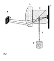
- the spatial brightness distribution of the object in the Fourier hologram is encoded in the form of angles. This is schematically in FIG. 1
- the Fourier hologram (2) When irradiating the Fourier hologram (2) with a collimated laser beam (7), the light beams are diffracted at different angles at the hologram.
- the angles can be returned to location information ( FIG. 1 and FIG. 2 ):
- the rays diffracted at the same angle are focused by the Fourier lens (5) into a point.
- the diffracted at different angles beams are focused by the Fourier lens in different points.
- the spots may be on a detector, e.g. a camera, are displayed and are thus processed electronically.
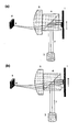
- FIG. 2 illustrates: If the Fourier hologram (2) is driven by the readout beam (7), an image appears on the detector as soon as the read beam hits the hologram partially. The intensity (brightness) of the image increases until the readout beam irradiates the entire hologram and then decreases again to zero until the readout beam no longer illuminates the hologram.
- this effect can be used to read out information stored in the form of Fourier holograms on a flat information carrier, while the information carrier is displaced in relation to an incident laser beam, for example moved manually by a guide.
- the hologram is only partially detected by the readout spot, the image is less bright and blurred than if the entire hologram is detected by the readout spot. From this it could easily be concluded that it is particularly favorable to design the readout spot larger than the hologram so that as many areas of the hologram as possible are captured by the readout spot during the readout process. This is not so. If the read spot is larger than the hologram, parts of the information carrier that do not have a hologram are always illuminated. As a result, generally less light rays are diffracted at the hologram, so that the brightness decreases. In addition, scattering effects due to irradiation of the information carrier outside the hologram lead to increased background noise on the detector.
- the imaging properties when irradiating the hologram are particularly good when the read spot is smaller than the hologram. More preferably, the readout spot is 0.9 to 0.1 times as large as the hologram.
- Particularly good imaging properties are achieved when several holograms with the same content are placed directly into a larger hologram.
- Particularly preferably, 2 to 9 holograms of the same content are placed directly against one another and thus form an enlarged hologram.
- the geometry of the Fourier holograms is adapted to the profile of the readout spots.
- Conventional lasers as the source of the readout beam generate a circular or elliptical readout spot in which the intensity decreases from the inside to the outside.
- Fig. 4 shows a Fourier hologram. This will be in Fig. 4 (b) quadrupled, with the four identical holograms arranged in the form of a rectangle. In Fig. 4 (c) the enlarged hologram is cut so that the hologram has the shape of the readout spot.
- the individual holograms are provided with a black frame, but in reality does not occur.
- the size of the holograms is preferably 0.1 to 5 mm in diameter.
- a device for reading the optical memory cards comprises a light source for a readout beam, a Fourier optics, a photodetector and a guide device, which aligns the information carrier during the movement during the read operation, in particular the manual passage through the device with respect to the readout beam and the photodetector.
- the guide restricts the movement of the information carrier in two spatial directions, while the information carrier is moved in the third spatial direction.
- the information carrier is for example moved manually through the guide and thereby illuminated with a light beam.
- the light beam is diffracted at the Fourier hologram of the information carrier and the diffracted beams are imaged by means of a Fourier optics onto a detector, where the optical signal is transformed into an electronic signal.
- the optical memory cards can be read out in transmission and / or reflection.
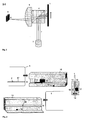
- FIG. 3 An example of an embodiment of such a device with which memory cards are read out in reflection is shown in FIG. 3 shown.
- It consists of two guide rails (10 and 11) between which the information carrier (1) is moved manually.
- One of the guide rails (here 10) has a roller (12) which is mounted with a pressure spring (13) and presses the information carrier (1) against the other rail (here 11) during manual pulling.
- the roll is slightly tilted, so that an information carrier is automatically pushed down while pulling.
- the information carrier is pressed during manual passage both against a rail (here 11) and against the bottom of the guide. This limits two of the three possible spatial directions. In the third spatial direction, parallel to the guide rails 10 and 11, the information carrier is moved.
- the bore (16) is arranged in the height of the hologram (2) on the information carrier (1).
- a groove (15) milled, which prevents a hologram located on the information carrier is gradually scratched by repeated passage through the guide.
- a detector (14) is inserted in the guide, which detects whether an information carrier is moved by the guide.
- a forked light barrier can be used whose light beam is interrupted by the information carrier. The interruption of the light beam of the light barrier can be used as a trigger for the readout beam (3) and the detector (camera) (6). As soon as the light barrier is interrupted, the readout beam is switched on and the image on the camera is evaluated.
- holograms can be read one after the other.
- the holograms are then arranged on the information carrier at a height along a line (9) in the storage medium (17).
- said device as a card reader for information carriers in the form of plastic cards of all kinds (bank cards, credit cards, ID cards, etc.) is provided.
- the present invention relates to a method for data transmission, which comprises (a) storing the data in the form of at least one Fourier hologram on a flat information carrier, for example a plastic card, and (b) the information carrier by a device comprising a Fourier optics, a photodetector and a guiding device , which aligns the information carrier during movement through the device in relation to the readout beam and the photodetector, and to read out the stored data.
- a device comprising a Fourier optics, a photodetector and a guiding device , which aligns the information carrier during movement through the device in relation to the readout beam and the photodetector, and to read out the stored data.
- the movement of the information carrier by the device during the read operation by manual passage.
- Another object of the present invention is a system for data transmission comprising at least one flat information carrier, for example a plastic card containing data stored in the form of at least one Fourier hologram, and at least one reading device comprising a Fourier optics, a photodetector and a guide device, which the information carrier during the Align movement during the read operation, in particular the manual passage through the device with respect to the readout beam and the photodetector.
- at least one flat information carrier for example a plastic card containing data stored in the form of at least one Fourier hologram
- at least one reading device comprising a Fourier optics, a photodetector and a guide device, which the information carrier during the Align movement during the read operation, in particular the manual passage through the device with respect to the readout beam and the photodetector.
- Such a system is useful for a variety of applications, such as authentication of persons or goods, or access control to buildings or premises.
Landscapes
- Physics & Mathematics (AREA)
- General Physics & Mathematics (AREA)
- Engineering & Computer Science (AREA)
- Theoretical Computer Science (AREA)
- Mathematical Physics (AREA)
- Holo Graphy (AREA)
- Optical Recording Or Reproduction (AREA)
- Credit Cards Or The Like (AREA)
- Investigating Or Analysing Materials By The Use Of Chemical Reactions (AREA)
- Optical Record Carriers And Manufacture Thereof (AREA)
Description
- Die vorliegende Erfindung betrifft ein Verfahren und eine Vorrichtung, mit der ein Informationsträger ausgelesen werden kann, auf dem Informationen in Form von Beugungsstrukturen gespeichert sind. Der Informationsträger kann durch manuellen Durchzug durch eine Auslesevorrichtung ausgelesen werden.
- Plastikkarten als Informationsträger sind heutzutage allgegenwärtig. In Folge der zunehmenden maschinellen Datenverarbeitung verfügt eine Person typischerweise über eine Reihe von Plastikkarten, mit denen sie sich authentifizieren kann. Als Beispiele seien Firmenausweise, Krankenkassenausweise, Kredit-, EC- und Payback-Karten genannt.
- Besonders verbreitet ist das Format ID-1, das in dem Standard ISO/IEC 7810 charakterisiert ist ("Kreditkartenformat"). Es hat eine handliche Größe und lässt sich in Portemonnaies unterbringen. Es gibt viele Kartenlesegeräte, die auf dieses Format ausgerichtet sind.
- Auf Plastikkarten können auf verschiedene Weisen maschinenlesbare Informationen abgelegt werden. Z.B. optisch in Form von optisch lesbaren Buchstaben (OCR = Optical Character Recognition), Bar- oder Matrixcodes, magnetisch in einem Magnetstreifen oder elektronisch in einem Chip. Die genannten Speichermethoden erlauben jedoch lediglich die Speicherung von wenigen Bytes (OCR) bis Kilobytes (Chip). Die größte Speicherkapazität bei Plastikkarten erreichen heute optische Speicherkarten.
- In
W08808120 (A1 EP0231351 (A1 ) sind optische Speicherkarten beschrieben, bei denen Daten fotografisch in einen Silberhalogenidfilm, der auf die Plastikkarten aufgebracht ist, belichtet werden. Die Daten können mit einem Laser eingeschrieben und ausgelesen werden. InW08808120 (A1 - Nachteilig an der beschriebenen Karte und dem Kartenleser ist, dass die Karte genau bezüglich Auslesestrahl und Detektor positioniert werden muss, um die Daten lesen zu können. Um die einzelnen Datenpunkte nacheinander auszulesen, muss die Karte ferner in Bezug zu Lesestrahl und Detektor so bewegt werden, dass der Lesestrahl die Datenpunkte genau trifft. Dies erfordert ein komplexes Kartenlesegerät mit einer hohen Positioniergenauigkeit. Darüber hinaus ist die Datendichte auf der Karte beschränkt auf das Maß der Positioniergenauigkeit beim Auslesen. Liegen die Datenpunkte dichter als die Positioniergenauigkeit des Lesestrahls ist, so können die einzelnen Datenpunkte nicht mehr detektiert werden.
- Bei der Benutzung von Barcode- oder Magnetstreifenkarten ist es möglich, die Karte zum Auslesen durch eine Kartenführung zu ziehen. Die Daten werden beim manuellen Durchziehen ausgelesen. Eine maschinelle Positionierung von Lesekopf in Bezug zur Karte ist nicht notwendig.
- Ein solches Kartendurchzugsystem für Magnetstreifenkarten ist z.B. beschrieben in
US5128524 (A1 ).EP 1 252 623 A beschreibt eine Vorrichtung zum Lesen von auf einer Karte gespeicherten Fourierhologrammen, welche zum Lesen der verschiedenen Hologramme eine Positionierung der Karte relativ zur Ausleseoptik vornimmt und dann in dieser Position die Hologramme liest.US 6 328 209 B1 beschreibt ein Leseverfahren für eine Karte mit einem als Fourierhologramm gespeicherten Barcode, einem Magnetstreifen und einem weiteren Hologramm als Identifikationsmerkmalen.US 5 336 871 A beschreibt ein manuelles Durchzugslesegerät für eine Karte mit holographisch gespeichertem Barcode. - Die Realisierung eines manuellen Kartendurchzugsystems zum Auslesen von Daten, die auf Plastikkarten gespeichert sind, ist bei Magnetstreifen und Barcodes möglich, weil die Datendichte (Menge der Bytes pro Flächeneinheit) so gering ist, dass die Positionierung des Speichermediums in Bezug zum Lesekopf tolerant gegenüber den Änderungen ist, die bei der manuellen Kartenführung auftreten.
- Bei den oben beschriebenen optischen Speicherkarten sind die Datenstrukturen kleiner. Eine manuelle Positionierung der Karte in Bezug zum Lesekopf ist daher in der Regel nicht mehr möglich.
- Es wäre aber wünschenswert, optische Speicherkarten mit einer höheren Speicherkapazität als bei Magnetstreifen- oder Barcode-Karten üblich, mit Hilfe eines manuell bedienbaren Kartendurchzugsystems auslesen zu können.
- Vorteile der manuellen Kartenführung sind zum einen der höhere Komfort für den Benutzer, da er die Karte nicht aus der Hand geben muss, eine hiermit verbundene erhöhte Geschwindigkeit des gesamten Leseprozesses und zum anderen geringere Herstellkosten des Geräts, da auf eine teure maschinelle Positionierung verzichtet werden kann, sowie auch eine höhere Robustheit des Geräts.
- Es bestand daher die Aufgabe, eine optische Speicherkarte bereitzustellen, die mit Hilfe eines manuell bedienbaren Kartendurchzugsystems auslesbar ist.
- Überraschend wurde gefunden, dass diese Aufgabe durch die nachfolgend beschriebenen optischen Speicherkarten gelöst wird.
- Insbesondere können die optischen Speicherkarten beim manuellen Durchzug durch eine Kartenführung ausgelesen werden, obwohl die Strukturen, welche die Daten im Speichermedium repräsentieren, kleiner sind als die Positioniergenauigkeit beim manuellen Durchzug.
- Weiterhin weisen die optischen Speicherkarten eine höhere Speicherkapazität als die aus dem Stand der Technik bekannten Speicherkarten auf.
- Dies wird erreicht durch Informationsträger, insbesondere optische Speicherkarten, auf denen Daten in Form von Fourierhologrammen gespeichert sind.
- In einer Ausführungsform liegen die auszulesenden Informationen (Daten) in Form von Fourierhologrammen auf einem flachen Informationsträger, beispielsweise einer Plastikkarte vor.
- Als Speichermedium für das Hologramm kommen alle üblichen und dem Fachmann bekannten Materialien in Betracht, bei denen sich eine flache Oberfläche erzeugen lässt. Beispiele hierfür sind Polymere, Metalle, Papiere, Textilien, Lacke, Steingut u.a., in denen die holographischen Strukturen mittels Prägung, Ätzung, Fotolithographie, Granolithographie, Abrasion oder Schneidung eingebracht sind. Es sind auch Verbundmaterialien denkbar, die durch Kombination der oben genannten Materialien gebildet werden. Ein Beispiel hierfür sind Polymerfolien, auf denen ein Metallfilm aufgebracht ist. Bei photosensitiven Materialien oder Verbundmaterialien mit photosensitiven Komponenten können die holographischen Strukturen auch mit Licht eingebracht werden (Silberhalogenidfilm, Film aus photoadressierbarem Polymer, u.a.).
- Als flacher Informationsträger wird ein Informationsträger verstanden, der einen Krümmungsradius aufweist, der wesentlich größer ist als der Informationsträger selbst. Ein solcher flacher Informationsträger ist zum Beispiel eine Kreditkarte, die im Portemonnaie so verbogen wurde, so dass sie einen Krümmungsradius von 3 m aufweist, während die Karte selbst nur etwa 8 cm lang und etwa 5 cm breit ist.
- Das Speichermedium für das Hologramm kann dabei sowohl Teil des Informationsträgers selbst sein als auch lediglich mit dem Informationsträger fest verbunden sein.
- Die Hologramme können in Reflexion oder Transmission ausgelesen werden. Sie werden bevorzugt in Reflexion ausgelesen. Dazu ist eine lichtreflektierende Oberfläche erforderlich, auf die das Hologramm aufgebracht oder in die das Hologramm eingebracht ist.
- Der Informationsträger sollte bevorzugt glatt sein, das heißt die Rauhigkeit sollte kleiner sein als die holographischen Strukturen. Die Rauhigkeit kann z.B. mittels Taststiftverfahren (Messgerät: KLA Tencor Alpha Step 500; Messmethode: MM-40001) bestimmt werden. Die Oberflächenrauhigkeit liegt bevorzugt unterhalb von Ra = 10 Mikrometern.
- Die holographisch zu speichernden Daten liegen bevorzugt als zweidimensionale Verteilung von Helligkeitswerten vor. Als Beispiel sei der Data Matrix Code genannt, der in ISO/IEC 16022 spezifiziert ist.
- Bei der Speicherung solcher Daten als Fourierhologramme wird die räumliche Helligkeitsverteilung des Objekts im Fourierhologramm in Form von Winkeln kodiert. Dies ist schematisch in
Figur 1 dargestellt: Beim Bestrahlen des Fourierhologramms (2) mit einem kollimierten Laserstrahl (7) werden die Lichtstrahlen am Hologramm unter verschiedenen Winkel gebeugt. - Fourierhologramme sind bekannt und ihre Eigenschaften z.B. beschrieben in P. Hariharan, Basics of Holography, Cambridge University Press, 2002, Seiten 8 bis 10.
- Mit Hilfe einer Fourieroptik können die Winkel wieder in Ortsinformationen zurückgeführt werden (
Figur 1 undFigur 2 ): Die unter demselben Winkel gebeugten Strahlen werden durch die Fourierlinse (5) in einen Punkt fokussiert. Die unter verschiedenen Winkeln gebeugten Strahlen werden durch die Fourierlinse in verschiedene Punkte fokussiert. - Die Punkte können auf einem Detektor, z.B. einer Kamera, abgebildet werden und sind somit elektronisch weiterverarbeitbar.
- Eine wichtige Eigenschaft der Fourierhologramme in Kombination mit einer Fourieroptik besteht darin, dass sich die auf dem Detektor abgebildeten Punkte nicht verschieben, wenn das Hologramm senkrecht zum einfallenden Laserstrahl verschoben wird. Es ändert sich lediglich die Intensität der Abbildung auf dem Detektor. Dies ist in
Figur 2 verdeutlicht: Wird das Fourierhologramm (2) durch den Auslesestrahl (7) gefahren, erscheint auf dem Detektor ein Abbild, sobald der Auslesestrahl das Hologramm partiell trifft. Die Intensität (Helligkeit) der Abbildung steigt, bis der Auslesestrahl das gesamte Hologramm bestrahlt und nimmt dann wieder auf Null ab, bis der Auslesestrahl das Hologramm nicht mehr beleuchtet. - Überraschend wurde festgestellt, dass dieser Effekt dazu verwendet werden kann, Informationen, die in Form von Fourierhologrammen auf einem flachen Informationsträger gespeichert sind, auszulesen, während der Informationsträger in Bezug zu einem einfallenden Laserstrahl verschoben, also beispielsweise manuell durch eine Führung bewegt wird.
- Wird das Hologramm nur teilweise vom Auslesespot erfasst, so ist die Abbildung weniger hell und unschärfer, als wenn das gesamte Hologramm vom Auslesespot erfasst wird. Daraus könnte leicht gefolgert werden, dass es besonders günstig ist, den Auslesespot größer als das Hologramm zu gestalten, damit beim Ausleseprozess immer möglichst viele Bereiche des Hologramms vom Auslesespot erfasst sind. Dies ist jedoch nicht so. Ist der Auslesespot größer als das Hologramm, so werden immer auch Teile des Informationsträgers beleuchtet, die kein Hologramm aufweisen. Dadurch werden generell weniger Lichtstrahlen am Hologramm gebeugt, so dass die Helligkeit sinkt. Daneben führen Streueffekte durch Bestrahlung des Informationsträgers außerhalb des Hologramms zu einem erhöhten Hintergrundrauschen auf dem Detektor.
- Überraschend wurde gefunden, dass die Abbildungseigenschaften beim Bestrahlen des Hologramms besonders gut sind, wenn der Auslesespot kleiner als das Hologramm ist. Besonders bevorzugt ist der Auslesespot 0,9- bis 0,1-mal so groß wie das Hologramm.
- Besonders gute Abbildungseigenschaften werden erzielt, wenn mehrere Hologramme mit demselben Inhalt zu einem größeren Hologramm direkt aneinandergesetzt werden. Besonders bevorzugt werden 2 bis 9 Hologramme desselben Inhalts direkt aneinandergesetzt und bilden damit ein vergrößertes Hologramm.
- Bevorzugt wird die Geometrie der Fourierhologramme an das Profil des Auslesespots angepasst. Konventionelle Laser als Quelle des Auslesestrahls erzeugen einen kreis- oder elliptischförmigen Auslesespot, bei dem die Intensität von innen nach außen abnimmt.
- Besonders gute Abbildungen erhält man, wenn man vier Hologramme desselben Inhalts zu einem größeren Hologramm zusammensetzt, von dem nur ein mittlerer kreis- oder elliptischförmiger Bereich, der etwas größer als der Auslesespot ist, auf den Informationsträger aufgebracht wird, wie in
Fig. 4 dargestellt:Fig. 4 (a) zeigt ein Fourierhologramm. Dieses wird inFig. 4 (b) vervierfacht, wobei die vier identischen Hologramme in Form eines Rechtecks angeordnet werden. InFig. 4 (c) ist das vergrößerte Hologramm so geschnitten, dass das Hologramm die Form des Auslesespots besitzt. Zur besseren Verdeutlichung sind inFig. 4 die einzelnen Hologramme mit einem schwarzen Rahmen versehen, der aber in Wirklichkeit nicht auftritt. - Die Größe der Hologramme beträgt bevorzugt 0,1 bis 5 mm im Durchmesser.
- Eine Vorrichtung zum Auslesen der optischen Speicherkarten
umfasst eine Lichtquelle für einen Auslesestrahl, eine Fourieroptik, einen Fotodetektor und eine Führungsvorrichtung, welche den Informationsträger während der Bewegung während des Auslesevorgangs, insbesondere des manuellen Durchzugs durch die Vorrichtung in Bezug zum Auslesestrahl und zum Fotodetektor ausrichtet. Die Führung schränkt die Bewegung des Informationsträgers in zwei Raumrichtungen ein, während der Informationsträger in die dritte Raumrichtung bewegt wird. Der Informationsträger wird beispielsweise manuell durch die Führung bewegt und dabei mit einem Lichtstrahl beleuchtet. Der Lichtstrahl wird am Fourierhologramm des Informationsträgers gebeugt und die gebeugten Strahlen werden mit Hilfe einer Fourieroptik auf einen Detektor abgebildet, wo das optische Signal in ein elektronisches Signal transformiert wird. - Mit der Vorrichtung können die optischen Speicherkarten in Transmission und/oder Reflexion ausgelesen werden.
- Ein Beispiel für eine Ausführung einer solchen Vorrichtung, mit der Speicherkarten in Reflexion ausgelesen werden, ist in
Figur 3 dargestellt. Sie besteht aus zwei Führungsschienen (10 und 11) zwischen denen der Informationsträger (1) manuell bewegt wird. Eine der Führungsschienen (hier 10) verfügt über eine Rolle (12), die mit einer Andrückfeder (13) gelagert ist und den Informationsträger (1) beim manuellen Durchzug gegen die andere Schiene (hier 11) drückt. Die Rolle ist etwas gekippt, sodass ein Informationsträger beim Durchzug automatisch nach unten gedrückt wird. Damit wird der Informationsträger beim manuellen Durchzug sowohl gegen eine Schiene (hier 11) als auch gegen den Boden der Führung gedrückt. Damit sind zwei der drei möglichen Raumrichtungen eingeschränkt. In die dritte Raumrichtung, parallel zu den Führungsschienen 10 und 11, wird der Informationsträger bewegt. - Dabei überstreicht er den Auslesestrahl (7), der durch eine Bohrung (16) in einer der Führungsschienen (hier 11) fällt. Die Bohrung (16) ist in der Höhe des Hologramms (2) auf dem Informationsträger (1) angeordnet. Bevorzugt ist in derselben Höhe, in der Schiene, die dem Hologramm zugewandt ist und in der sich die Bohrung befindet, eine Nut (15) gefräst, die verhindert, dass ein auf dem Informationsträger befindliches Hologramm bei mehrmaligem Durchzug durch die Führung allmählich zerkratzt wird.
- Bevorzugt ist in der Führung ein Detektor (14) eingefügt, der erkennt, ob ein Informationsträger durch die Führung bewegt wird. Z.B. kann eine Gabellichtschranke verwendet werden, deren Lichtstrahl durch den Informationsträger unterbrochen wird. Die Unterbrechung des Lichtstrahls der Lichtschranke kann als Trigger für den Auslesestrahl (3) und den Detektor (Kamera) (6) verwendet werden. Sobald die Lichtschranke unterbrochen wird, wird der Auslesestrahl eingeschaltet und das Bild auf der Kamera ausgewertet.
- Es ist auch möglich, die Kamera mit einer definierten Zeitverzögerung zum Auslesestrahl einzuschalten.
- Es ist ebenso denkbar, mehrere Lichtschranken zu verwenden.
- Es können auch mehrere Hologramme nacheinander ausgelesen werden. Die Hologramme sind dann auf dem Informationsträger in einer Höhe, entlang einer Linie (9) im Speichermedium (17) angeordnet.
- Bei der Verwendung von mehreren Hologrammen auf einem Informationsträger, die entlang einer Linie angeordnet sind, ist es denkbar, neben den Hologrammen auch noch Markierungen in den Informationsträger und/oder das Speichermedium einzufügen, die als Trigger für die Kamera und/oder den Auslesestrahl fungieren. Auf diese Weise ist es einfach möglich, der Kamera zu signalisieren, wann ein neues Hologramm abgebildet wird.
- Weiterhin ist auch die Verwendung der genannten Vorrichtung als Kartenleser für Informationsträger in Form von Plastikkarten aller Art (Bankkarten, Kreditkarten, Ausweise, etc.) vorgesehen.
- Gegenstand der vorliegenden Erfindung ist ein Verfahren zur Datenübermittlung, welches umfasst (a) die Daten in Form mindestens eines Fourierhologramms auf einem flachen Informationsträger, beispielsweise einer Plastikkarte zu speichern und (b) den Informationsträger durch eine Vorrichtung umfassend eine Fourieroptik, einen Fotodetektor und eine Führungsvorrichtung, welche den Informationsträger während der Bewegung durch die Vorrichtung in Bezug zum Auslesestrahl und zum Fotodetektor ausrichtet, zu bewegen und so die gespeicherten Daten auszulesen. Bevorzugt erfolgt die Bewegung des Informationsträgers durch die Vorrichtung während des Auslesevorgangs durch manuellen Durchzug.
- Ein weiterer Gegenstand der vorliegenden Erfindung ist ein System zur Datenübermittlung umfassend mindestens einen flachen Informationsträger, beispielsweise eine Plastikkarte, der Daten in Form mindestens eines Fourierhologramms gespeichert enthält, und mindestens eine Lesevorrichtung umfassend eine Fourieroptik, einen Fotodetektor und eine Führungsvorrichtung, welche den Informationsträger während der Bewegung während des Auslesevorgangs, insbesondere des manuellen Durchzugs durch die Vorrichtung in Bezug zum Auslesestrahl und zum Fotodetektor ausrichtet.
- Ein solches System ist für eine Vielzahl von Anwendungen brauchbar, so beispielsweise für die Authentifizierung von Personen oder Gütern oder die Zugangskontrolle zu Gebäuden oder Räumen.
-
- 1
- Informationsträger (Plastikkarte)
- 2
- Fourierhologramm
- 3
- Lichtquelle mit Kollimationsoptik
- 4
- Strahlteiler
- 5
- Fourierlinse
- 6
- Detektor (Kamera)
- 7
- Kollimierter Lichtstrahl (Auslesestrahl)
- 8
- Abbildung auf der Kamera
- 9
- Linie, entlang derer Hologramm gespeichert werden können
- 10
- Führungsschiene 1
- 11
- Führungsschiene 2
- 12
- Rolle
- 13
- Andrückfeder
- 14
- Detektor (Gabellichtschranke)
- 15
- Nut
- 16
- Bohrung für Auslesestrahl
- 17
- Speichermedium
Claims (6)
- System zur Datenübermittlung umfassend mindestens einen flachen Informationsträger, der Daten in Form von Fourierhologrammen, die entlang einer Linie angeordnet sind, gespeichert enthält, und mindestens eine Lesevorrichtung umfassend eine Lichtquelle zur Erzeugung eines Auslesestrahls, eine Fourieroptik, einen Fotodetektor, gekennzeichnet durch eine Führungsvorrichtung, welche die Bewegung des Informationsträgers während des manuellen Durchzugs durch die Lesevorrichtung in zwei Raumrichtungen einschränkt, während der Informationsträger beim. Auslesen der Fonriethologramme in die dritte Raumrichtung in Bezug zum Auslesestrahl und zum Fotodetektor manuell bewegt wird.
- Verwendung des Systems nach Anspruch 1 zur Authentifizierung oder zur Zugangskontrolle.
- Verfahren zur Datenübermittlung, welches umfasst (a) die Daten in Form von Fourierhologrammen entlang einer Linie auf einem flachen Informationsträger, insbesondere einer Plastikkarte zu speichern und (b) den Informationsträger durch eine Vorrichtung umfassend eine Lichtquelle zur Erzeugung eines Auslesestrahls, eine Fourieroptik, einen Fotodetektor und eine Führungsvorrichtung, welche den Informationsträger während der Bewegung durch die Vorrichtung in Bezug zum Auslesestrahl und zum Fotodetektor ausrichtet, manuell zu bewegen und dabei mehrere Fourierhologramme nacheinander auszulesen.
- Verfahren nach Anspruch 3, dadurch gekennzeichnet, dass der beim Auftreffen des Auslesestrahls auf ein Fourierhologramm entstehende Auslesespot kleiner als das Fourierhologramm ist.
- Verfahren nach Anspruch 3 oder 4, dadurch gekennzeichnet, dass mehrere identische Fourierhologramme zu einem größeren Hologramm zusammengesetzt sind.
- Verfahren nach einem der Ansprüche 3 bis 5, dadurch gekennzeichnet, dass auf dem Informationsträger Markierungen aufgebracht sind, die als Trigger-Signal für den Auslesestrahl und/oder den Detektor dienen.
Applications Claiming Priority (2)
| Application Number | Priority Date | Filing Date | Title |
|---|---|---|---|
| DE102006012991A DE102006012991A1 (de) | 2006-03-22 | 2006-03-22 | Verfahren und Vorrichtung zum optischen Auslesen von Informationen |
| PCT/EP2007/002060 WO2007107251A1 (de) | 2006-03-22 | 2007-03-09 | Verfahren und vorrichtung zum optischen auslesen von informationen |
Publications (2)
| Publication Number | Publication Date |
|---|---|
| EP2002433A1 EP2002433A1 (de) | 2008-12-17 |
| EP2002433B1 true EP2002433B1 (de) | 2010-05-26 |
Family
ID=38180682
Family Applications (1)
| Application Number | Title | Priority Date | Filing Date |
|---|---|---|---|
| EP07723140A Not-in-force EP2002433B1 (de) | 2006-03-22 | 2007-03-09 | Verfahren und system zum optischen auslesen von informationen |
Country Status (15)
| Country | Link |
|---|---|
| US (2) | US8915436B2 (de) |
| EP (1) | EP2002433B1 (de) |
| JP (1) | JP2009530725A (de) |
| AT (1) | ATE469416T1 (de) |
| AU (1) | AU2007229100B2 (de) |
| CA (1) | CA2646581A1 (de) |
| DE (2) | DE102006012991A1 (de) |
| DK (1) | DK2002433T3 (de) |
| ES (1) | ES2344811T3 (de) |
| IL (1) | IL194084A (de) |
| NO (1) | NO20084420L (de) |
| PT (1) | PT2002433E (de) |
| RU (1) | RU2446486C2 (de) |
| TW (1) | TW200809653A (de) |
| WO (1) | WO2007107251A1 (de) |
Families Citing this family (5)
| Publication number | Priority date | Publication date | Assignee | Title |
|---|---|---|---|---|
| EP2463645A1 (de) | 2010-12-08 | 2012-06-13 | Roche Diagnostics GmbH | Verbrauchsmaterial zum Messen einer Analytkonzentration einer Körperflüssigkeitsprobe, Leser zum Lesen eines optischen Datenspeichers eines solchen Verbrauchsmaterials sowie Messsystem |
| JP2014029370A (ja) * | 2012-07-31 | 2014-02-13 | Alps Electric Co Ltd | ホログラムを用いた真贋判定システム |
| US20150028110A1 (en) * | 2013-07-29 | 2015-01-29 | Owens-Brockway Glass Container Inc. | Container with a Data Matrix Disposed Thereon |
| DE102020210936A1 (de) | 2020-08-31 | 2022-03-03 | Scribos Gmbh | Auslesevorrichtung zum Auslesen holographisch abgelegter Informationen, Verfahren zum Auslesen holographisch abgelegter Informationen, und Auslesesystem zum Auslesen von holographisch abgelegten Informationen. |
| DE102020210935B3 (de) | 2020-08-31 | 2021-09-30 | Tesa Scribos Gmbh | Auslesevorrichtung zum Auslesen holographisch abgelegter Informationen, Verfahren zum Auslesen holographisch abgelegter Informationen |
Family Cites Families (54)
| Publication number | Priority date | Publication date | Assignee | Title |
|---|---|---|---|---|
| US3328209A (en) * | 1963-01-07 | 1967-06-27 | Engelhard Ind Inc | Noble metal thermocouple having base metal compensating leads |
| US3483513A (en) * | 1967-05-16 | 1969-12-09 | Bell Telephone Labor Inc | Holographic matched filter pattern recognition technique |
| US3643216A (en) * | 1968-08-06 | 1972-02-15 | Rca Corp | Holographic identification system |
| GB1542884A (en) * | 1975-04-01 | 1979-03-28 | Asahi Chemical Ind | Recording and reproducing holograms |
| JPS523413A (en) * | 1975-06-26 | 1977-01-11 | Sankyo Seiki Mfg Co Ltd | Magnetic recording device |
| GB1533952A (en) | 1976-02-25 | 1978-11-29 | Sterling Drug Inc | Anti-microbial bis-pyridinium compounds |
| US4683371A (en) * | 1981-02-27 | 1987-07-28 | Drexler Technology Corporation | Dual stripe optical data card |
| JPH03213840A (ja) | 1988-11-22 | 1991-09-19 | Canon Inc | 背面投射型スクリーン及びこれを用いた背面投射型画像表示装置 |
| US4837134A (en) * | 1986-08-15 | 1989-06-06 | Drexler Technology Corporation | Optical memory card with versatile storage medium |
| WO1988008120A1 (en) | 1987-04-16 | 1988-10-20 | Drexler Technology Corporation | Optical memory card with versatile storage medium |
| JPH022217A (ja) | 1988-06-15 | 1990-01-08 | Matsushita Electric Ind Co Ltd | 位相同期検出回路 |
| DE4025146A1 (de) | 1990-08-08 | 1992-02-27 | Teckentrup Gmbh & Co Kg | Federnde scheibe zum sichern von schrauben, muttern oder dergleichen |
| US5128524A (en) * | 1990-11-23 | 1992-07-07 | Verifone, Inc. | Data carrier reader apparatus for selective data track reading |
| JP2874042B2 (ja) * | 1991-05-16 | 1999-03-24 | 日本発条株式会社 | 磁気記憶カード |
| GB9113462D0 (en) * | 1991-06-21 | 1991-08-07 | Pizzanelli David J | Laser-activated bar-code holograms and bar-code recognition system |
| US5644412A (en) | 1991-12-25 | 1997-07-01 | Dai Nippon Printing Co., Ltd. | Hologram and method of reading the same |
| US5336871A (en) | 1992-02-07 | 1994-08-09 | American Bank Note Holographics, Incorporated | Holographic enhancement of card security |
| US5432329A (en) * | 1992-02-07 | 1995-07-11 | American Bank Note Holographics | Automated holographic optical recognition and decoding system for verification |
| US5344808A (en) * | 1992-09-09 | 1994-09-06 | Toppan Printing Co., Ltd. | Intermediate transfer medium and process for producing image-recorded article making use of the same |
| US5412195A (en) * | 1992-12-29 | 1995-05-02 | Hughes Aircraft Company | High security spectral code strip |
| GB9309673D0 (en) * | 1993-05-11 | 1993-06-23 | De La Rue Holographics Ltd | Security device |
| JP3292332B2 (ja) * | 1993-08-26 | 2002-06-17 | 大日本印刷株式会社 | 情報記録媒体及びその読み取り方法 |
| JPH07210071A (ja) * | 1994-01-25 | 1995-08-11 | Nhk Spring Co Ltd | 対象物の識別システム |
| JPH07239648A (ja) * | 1994-02-28 | 1995-09-12 | A M C:Kk | データの正当性認識方法およびそれに用いる記録体および認識装置 |
| JPH07304286A (ja) * | 1994-08-12 | 1995-11-21 | Dainippon Printing Co Ltd | ホログラムカード |
| US5986781A (en) * | 1996-10-28 | 1999-11-16 | Pacific Holographics, Inc. | Apparatus and method for generating diffractive element using liquid crystal display |
| US6005691A (en) * | 1996-12-11 | 1999-12-21 | Hewlett-Packard Company | High-security machine-readable holographic card |
| DE19705170A1 (de) * | 1997-02-11 | 1998-08-20 | Orga Kartensysteme Gmbh | Taschenfräsanlage für Chipkarten |
| DE19812160C1 (de) | 1998-03-20 | 1999-07-08 | Bayer Ag | Formkörper aus wirkstoffhaltigen thermoplastischen Polyurethanen |
| US6616043B2 (en) * | 1998-04-07 | 2003-09-09 | Victor Zazzu | Multi sensor information reader |
| US6608911B2 (en) * | 2000-12-21 | 2003-08-19 | Digimarc Corporation | Digitally watermaking holograms for use with smart cards |
| HU9801029D0 (en) | 1998-05-05 | 1998-06-29 | Optilink Ab | Method and system for recording information on a holographic card |
| US6068301A (en) * | 1998-05-26 | 2000-05-30 | Han; Wenyu | Method and apparatus for impeding the counterfeiting of cards, instruments and documents |
| JP2000057268A (ja) * | 1998-08-04 | 2000-02-25 | Japan Steel Works Ltd:The | 磁気カードリーダーおよび磁気カードライター |
| WO2000007574A1 (de) | 1998-08-06 | 2000-02-17 | Schierholz Joerg | Medizinprodukte mit retardierter pharmakologischer aktivität und verfahren zu ihrer herstellung |
| DE19852192C2 (de) | 1998-11-12 | 2003-04-24 | Bayer Ag | Wirkstoffhaltige aromatische Copolyester |
| US6263104B1 (en) * | 1998-12-31 | 2001-07-17 | Mcgrew Stephen P. | Method and apparatus for reading and verifying holograms |
| US6328209B1 (en) * | 1999-02-03 | 2001-12-11 | American Bank Note Holographics, Inc. | Card security system |
| JP3620700B2 (ja) * | 1999-03-15 | 2005-02-16 | 日本ビクター株式会社 | 光記録媒体及び光記録媒体再生装置 |
| US6452699B1 (en) * | 1999-09-28 | 2002-09-17 | Holospex, Inc. | Controlled diffraction efficiency far field viewing devices |
| JP2001118123A (ja) * | 1999-10-18 | 2001-04-27 | Victor Co Of Japan Ltd | 光学情報読み取り装置及び光記録媒体 |
| HUP0000518D0 (en) | 2000-02-04 | 2000-04-28 | Method of placing data signals onto a carrier; method and apparatus for the holographic recording and read-out of data | |
| JP2001319340A (ja) * | 2000-05-10 | 2001-11-16 | Victor Co Of Japan Ltd | 光記録媒体読み取り装置 |
| JP2002288604A (ja) * | 2001-03-27 | 2002-10-04 | Topcon Corp | カードの真贋判定装置 |
| JP2002283775A (ja) * | 2001-03-27 | 2002-10-03 | Topcon Corp | カードの真贋判定装置 |
| US6651886B2 (en) * | 2001-04-13 | 2003-11-25 | Symbol Technologies, Inc. | Optical code readers with holographic optical elements |
| GB0117391D0 (en) * | 2001-07-17 | 2001-09-05 | Optaglio Ltd | Optical device and method of manufacture |
| DE10146508C2 (de) * | 2001-09-21 | 2003-07-24 | Ovd Kinegram Ag Zug | Etikett mit einem diffraktiven Strichcode und Leseanordnung für solche Etiketten |
| US7212323B2 (en) * | 2002-03-15 | 2007-05-01 | Coded Imagery, Inc. | Methods and apparatus for mass manufacturing two-dimensional binary information on transparent substrates using phase contrast modulated templates |
| US6961159B2 (en) * | 2002-08-02 | 2005-11-01 | Dai Nippon Printing Co, Ltd. | Holographic viewing device, and computer-generated hologram for the same |
| DE10345898A1 (de) * | 2003-07-11 | 2005-01-27 | Tesa Scribos Gmbh | Verfahren zum Berechnen und zum Erzeugen eines computergenerierten Hologramms sowie ein Speichermedium mit einem computergenerierten Hologramm und eine Lesevorrichtung |
| JP2006318515A (ja) * | 2004-09-10 | 2006-11-24 | Ricoh Co Ltd | ホログラム素子及びその製造方法及び光ヘッド装置 |
| JP2006126791A (ja) * | 2004-09-28 | 2006-05-18 | Dainippon Printing Co Ltd | ホログラムとそれを用いたホログラム観察具 |
| JP2006272654A (ja) * | 2005-03-28 | 2006-10-12 | Fuji Xerox Co Ltd | ホログラム記録媒体 |
-
2006
- 2006-03-22 DE DE102006012991A patent/DE102006012991A1/de not_active Withdrawn
-
2007
- 2007-03-09 RU RU2008141445/28A patent/RU2446486C2/ru not_active IP Right Cessation
- 2007-03-09 CA CA002646581A patent/CA2646581A1/en not_active Abandoned
- 2007-03-09 EP EP07723140A patent/EP2002433B1/de not_active Not-in-force
- 2007-03-09 US US12/293,616 patent/US8915436B2/en not_active Expired - Fee Related
- 2007-03-09 WO PCT/EP2007/002060 patent/WO2007107251A1/de not_active Ceased
- 2007-03-09 ES ES07723140T patent/ES2344811T3/es active Active
- 2007-03-09 DE DE502007003938T patent/DE502007003938D1/de active Active
- 2007-03-09 JP JP2009500732A patent/JP2009530725A/ja active Pending
- 2007-03-09 AU AU2007229100A patent/AU2007229100B2/en not_active Ceased
- 2007-03-09 PT PT07723140T patent/PT2002433E/pt unknown
- 2007-03-09 DK DK07723140.5T patent/DK2002433T3/da active
- 2007-03-09 AT AT07723140T patent/ATE469416T1/de active
- 2007-03-21 TW TW096109628A patent/TW200809653A/zh unknown
- 2007-03-22 US US11/689,897 patent/US8534557B2/en not_active Expired - Fee Related
-
2008
- 2008-09-15 IL IL194084A patent/IL194084A/en not_active IP Right Cessation
- 2008-10-21 NO NO20084420A patent/NO20084420L/no not_active Application Discontinuation
Also Published As
| Publication number | Publication date |
|---|---|
| RU2446486C2 (ru) | 2012-03-27 |
| US8534557B2 (en) | 2013-09-17 |
| US8915436B2 (en) | 2014-12-23 |
| US20120037698A9 (en) | 2012-02-16 |
| EP2002433A1 (de) | 2008-12-17 |
| ES2344811T3 (es) | 2010-09-07 |
| US20080041955A1 (en) | 2008-02-21 |
| CA2646581A1 (en) | 2007-09-27 |
| NO20084420L (no) | 2008-12-04 |
| AU2007229100A1 (en) | 2007-09-27 |
| TW200809653A (en) | 2008-02-16 |
| DE502007003938D1 (de) | 2010-07-08 |
| JP2009530725A (ja) | 2009-08-27 |
| DK2002433T3 (da) | 2010-09-13 |
| RU2008141445A (ru) | 2010-04-27 |
| AU2007229100B2 (en) | 2012-04-12 |
| PT2002433E (pt) | 2010-07-21 |
| US20110121073A1 (en) | 2011-05-26 |
| IL194084A (en) | 2013-05-30 |
| ATE469416T1 (de) | 2010-06-15 |
| WO2007107251A1 (de) | 2007-09-27 |
| DE102006012991A1 (de) | 2007-10-11 |
Similar Documents
| Publication | Publication Date | Title |
|---|---|---|
| DE69927291T2 (de) | Verfahren zur validierung elektronischer wertkarten und digitaler ausweise unter benutzung eines optischen speichers | |
| EP0244498B1 (de) | Anordnung und Verfahren zur Ermittelung der Berechtigung von Personen durch Überprüfen ihrer Fingerabdrücke | |
| DE2601693C3 (de) | Verfahren zur Herstellung eines Dokuments und Vorrichtung zur Durchführung des Verfahrens | |
| DE2731726C2 (de) | Verfahren und Einrichtung zum Identifizieren von Dokumenten | |
| DE3126730C2 (de) | Vorrichtung zum Lesen von magnetisch und optisch aufgezeichneten Daten | |
| DE69325406T2 (de) | System und Verfahren zum Lesen eines Hologrammkodes | |
| DE60001647T2 (de) | Keilförmiger holographischer kollektor | |
| DE602004001454T2 (de) | Datenträger mit hochfrequenzdiffraktionselement, verfahren und system zum lesen von in dem datenträger gespeicherten daten | |
| DE3523813A1 (de) | Wertkarte | |
| DE3840037C2 (de) | Informationsträger für Sicherheitszwecke und deren Verwendung sowie System zum Auslesen des Inhalts eines Informationsträgers | |
| EP1196885A2 (de) | Leseanordnung für informationsstreifen mit optisch kodierter information | |
| EP2002433A1 (de) | Verfahren und vorrichtung zum optischen auslesen von informationen | |
| EP1307881A1 (de) | Holographischer datenspeicher | |
| EP0718834B1 (de) | Optischer Datenträger und Lesegerät für einen solchen Datenträger | |
| DE2643803A1 (de) | Verfahren zum herstellen von aufzeichnungen | |
| EP0010611A1 (de) | Personenkennkarte | |
| EP2895921B1 (de) | Verfahren zur herstellung eines volumenreflexions-hologramms mit verbesserter marker-ausbildung | |
| DE69322635T2 (de) | Betrugssicheres identifikationssystem | |
| DE60131740T2 (de) | Fälschungsabwehr-authentifizierungsverfahren für optische speicherkarten und hybride chipkarten | |
| DE102020210935B3 (de) | Auslesevorrichtung zum Auslesen holographisch abgelegter Informationen, Verfahren zum Auslesen holographisch abgelegter Informationen | |
| DE60124283T2 (de) | Optischer Datenträger mit einem auf optischer Beugung basierenden Code, und zugehöriges Lesegerät | |
| WO2022043062A1 (de) | Auslesevorrichtung zum auslesen holographisch abgelegter informationen, verfahren zum auslesen holographisch abgelegter informationen, und auslesesystem zum auslesen von holographisch abgelegten informationen | |
| EP3989007B1 (de) | Identitätskarte sowie verfahren zu dessen verifikation | |
| DE19527737A1 (de) | Anordnung mit einem Lesegerät und mit einem Informationsspeicher mit optischen und magnetischen Merkmalen | |
| DE3520278C2 (de) | Karte zur optischen Informationsspeicherung und -aufzeichnung und Verfahren zu deren Herstellung |
Legal Events
| Date | Code | Title | Description |
|---|---|---|---|
| PUAI | Public reference made under article 153(3) epc to a published international application that has entered the european phase |
Free format text: ORIGINAL CODE: 0009012 |
|
| 17P | Request for examination filed |
Effective date: 20081022 |
|
| AK | Designated contracting states |
Kind code of ref document: A1 Designated state(s): AT BE BG CH CY CZ DE DK EE ES FI FR GB GR HU IE IS IT LI LT LU LV MC MT NL PL PT RO SE SI SK TR |
|
| 17Q | First examination report despatched |
Effective date: 20090203 |
|
| GRAP | Despatch of communication of intention to grant a patent |
Free format text: ORIGINAL CODE: EPIDOSNIGR1 |
|
| RTI1 | Title (correction) |
Free format text: METHOD AND SYSTEM FOR OPTICALLY READING INFORMATION |
|
| DAX | Request for extension of the european patent (deleted) | ||
| GRAS | Grant fee paid |
Free format text: ORIGINAL CODE: EPIDOSNIGR3 |
|
| GRAA | (expected) grant |
Free format text: ORIGINAL CODE: 0009210 |
|
| AK | Designated contracting states |
Kind code of ref document: B1 Designated state(s): AT BE BG CH CY CZ DE DK EE ES FI FR GB GR HU IE IS IT LI LT LU LV MC MT NL PL PT RO SE SI SK TR |
|
| REG | Reference to a national code |
Ref country code: GB Ref legal event code: FG4D Free format text: NOT ENGLISH |
|
| REG | Reference to a national code |
Ref country code: CH Ref legal event code: EP |
|
| REG | Reference to a national code |
Ref country code: IE Ref legal event code: FG4D Free format text: LANGUAGE OF EP DOCUMENT: GERMAN |
|
| REF | Corresponds to: |
Ref document number: 502007003938 Country of ref document: DE Date of ref document: 20100708 Kind code of ref document: P |
|
| REG | Reference to a national code |
Ref country code: CH Ref legal event code: NV Representative=s name: E. BLUM & CO. AG PATENT- UND MARKENANWAELTE VSP |
|
| REG | Reference to a national code |
Ref country code: PT Ref legal event code: SC4A Free format text: AVAILABILITY OF NATIONAL TRANSLATION Effective date: 20100715 |
|
| REG | Reference to a national code |
Ref country code: NL Ref legal event code: T3 |
|
| REG | Reference to a national code |
Ref country code: ES Ref legal event code: FG2A Ref document number: 2344811 Country of ref document: ES Kind code of ref document: T3 |
|
| REG | Reference to a national code |
Ref country code: DK Ref legal event code: T3 |
|
| REG | Reference to a national code |
Ref country code: SE Ref legal event code: TRGR |
|
| LTIE | Lt: invalidation of european patent or patent extension |
Effective date: 20100526 |
|
| PG25 | Lapsed in a contracting state [announced via postgrant information from national office to epo] |
Ref country code: LT Free format text: LAPSE BECAUSE OF FAILURE TO SUBMIT A TRANSLATION OF THE DESCRIPTION OR TO PAY THE FEE WITHIN THE PRESCRIBED TIME-LIMIT Effective date: 20100526 |
|
| PG25 | Lapsed in a contracting state [announced via postgrant information from national office to epo] |
Ref country code: LV Free format text: LAPSE BECAUSE OF FAILURE TO SUBMIT A TRANSLATION OF THE DESCRIPTION OR TO PAY THE FEE WITHIN THE PRESCRIBED TIME-LIMIT Effective date: 20100526 Ref country code: SI Free format text: LAPSE BECAUSE OF FAILURE TO SUBMIT A TRANSLATION OF THE DESCRIPTION OR TO PAY THE FEE WITHIN THE PRESCRIBED TIME-LIMIT Effective date: 20100526 Ref country code: IS Free format text: LAPSE BECAUSE OF FAILURE TO SUBMIT A TRANSLATION OF THE DESCRIPTION OR TO PAY THE FEE WITHIN THE PRESCRIBED TIME-LIMIT Effective date: 20100926 |
|
| REG | Reference to a national code |
Ref country code: HU Ref legal event code: AG4A Ref document number: E008719 Country of ref document: HU |
|
| PG25 | Lapsed in a contracting state [announced via postgrant information from national office to epo] |
Ref country code: PL Free format text: LAPSE BECAUSE OF FAILURE TO SUBMIT A TRANSLATION OF THE DESCRIPTION OR TO PAY THE FEE WITHIN THE PRESCRIBED TIME-LIMIT Effective date: 20100526 Ref country code: CY Free format text: LAPSE BECAUSE OF FAILURE TO SUBMIT A TRANSLATION OF THE DESCRIPTION OR TO PAY THE FEE WITHIN THE PRESCRIBED TIME-LIMIT Effective date: 20100602 |
|
| REG | Reference to a national code |
Ref country code: IE Ref legal event code: FD4D |
|
| PG25 | Lapsed in a contracting state [announced via postgrant information from national office to epo] |
Ref country code: IE Free format text: LAPSE BECAUSE OF FAILURE TO SUBMIT A TRANSLATION OF THE DESCRIPTION OR TO PAY THE FEE WITHIN THE PRESCRIBED TIME-LIMIT Effective date: 20100526 Ref country code: EE Free format text: LAPSE BECAUSE OF FAILURE TO SUBMIT A TRANSLATION OF THE DESCRIPTION OR TO PAY THE FEE WITHIN THE PRESCRIBED TIME-LIMIT Effective date: 20100526 |
|
| PG25 | Lapsed in a contracting state [announced via postgrant information from national office to epo] |
Ref country code: SK Free format text: LAPSE BECAUSE OF FAILURE TO SUBMIT A TRANSLATION OF THE DESCRIPTION OR TO PAY THE FEE WITHIN THE PRESCRIBED TIME-LIMIT Effective date: 20100526 Ref country code: RO Free format text: LAPSE BECAUSE OF FAILURE TO SUBMIT A TRANSLATION OF THE DESCRIPTION OR TO PAY THE FEE WITHIN THE PRESCRIBED TIME-LIMIT Effective date: 20100526 Ref country code: CZ Free format text: LAPSE BECAUSE OF FAILURE TO SUBMIT A TRANSLATION OF THE DESCRIPTION OR TO PAY THE FEE WITHIN THE PRESCRIBED TIME-LIMIT Effective date: 20100526 |
|
| PLBE | No opposition filed within time limit |
Free format text: ORIGINAL CODE: 0009261 |
|
| STAA | Information on the status of an ep patent application or granted ep patent |
Free format text: STATUS: NO OPPOSITION FILED WITHIN TIME LIMIT |
|
| 26N | No opposition filed |
Effective date: 20110301 |
|
| PG25 | Lapsed in a contracting state [announced via postgrant information from national office to epo] |
Ref country code: GR Free format text: LAPSE BECAUSE OF FAILURE TO SUBMIT A TRANSLATION OF THE DESCRIPTION OR TO PAY THE FEE WITHIN THE PRESCRIBED TIME-LIMIT Effective date: 20100827 |
|
| REG | Reference to a national code |
Ref country code: DE Ref legal event code: R097 Ref document number: 502007003938 Country of ref document: DE Effective date: 20110228 |
|
| PG25 | Lapsed in a contracting state [announced via postgrant information from national office to epo] |
Ref country code: MC Free format text: LAPSE BECAUSE OF NON-PAYMENT OF DUE FEES Effective date: 20110331 |
|
| PG25 | Lapsed in a contracting state [announced via postgrant information from national office to epo] |
Ref country code: MT Free format text: LAPSE BECAUSE OF FAILURE TO SUBMIT A TRANSLATION OF THE DESCRIPTION OR TO PAY THE FEE WITHIN THE PRESCRIBED TIME-LIMIT Effective date: 20100526 |
|
| REG | Reference to a national code |
Ref country code: DE Ref legal event code: R081 Ref document number: 502007003938 Country of ref document: DE Owner name: BAYER INNOVATION GMBH, DE Free format text: FORMER OWNER: BAYER INNOVATION GMBH, 40225 DUESSELDORF, DE Effective date: 20130118 |
|
| PGFP | Annual fee paid to national office [announced via postgrant information from national office to epo] |
Ref country code: FI Payment date: 20130312 Year of fee payment: 7 Ref country code: SE Payment date: 20130312 Year of fee payment: 7 Ref country code: HU Payment date: 20130222 Year of fee payment: 7 |
|
| PG25 | Lapsed in a contracting state [announced via postgrant information from national office to epo] |
Ref country code: LU Free format text: LAPSE BECAUSE OF NON-PAYMENT OF DUE FEES Effective date: 20110309 |
|
| PGFP | Annual fee paid to national office [announced via postgrant information from national office to epo] |
Ref country code: PT Payment date: 20130220 Year of fee payment: 7 |
|
| PG25 | Lapsed in a contracting state [announced via postgrant information from national office to epo] |
Ref country code: BG Free format text: LAPSE BECAUSE OF FAILURE TO SUBMIT A TRANSLATION OF THE DESCRIPTION OR TO PAY THE FEE WITHIN THE PRESCRIBED TIME-LIMIT Effective date: 20100826 Ref country code: TR Free format text: LAPSE BECAUSE OF FAILURE TO SUBMIT A TRANSLATION OF THE DESCRIPTION OR TO PAY THE FEE WITHIN THE PRESCRIBED TIME-LIMIT Effective date: 20100526 |
|
| PGFP | Annual fee paid to national office [announced via postgrant information from national office to epo] |
Ref country code: DK Payment date: 20140311 Year of fee payment: 8 Ref country code: CH Payment date: 20140312 Year of fee payment: 8 Ref country code: NL Payment date: 20140226 Year of fee payment: 8 |
|
| PGFP | Annual fee paid to national office [announced via postgrant information from national office to epo] |
Ref country code: AT Payment date: 20140226 Year of fee payment: 8 Ref country code: FR Payment date: 20140311 Year of fee payment: 8 Ref country code: IT Payment date: 20140306 Year of fee payment: 8 |
|
| PGFP | Annual fee paid to national office [announced via postgrant information from national office to epo] |
Ref country code: GB Payment date: 20140305 Year of fee payment: 8 |
|
| PGFP | Annual fee paid to national office [announced via postgrant information from national office to epo] |
Ref country code: BE Payment date: 20140312 Year of fee payment: 8 |
|
| PGFP | Annual fee paid to national office [announced via postgrant information from national office to epo] |
Ref country code: DE Payment date: 20140417 Year of fee payment: 8 Ref country code: ES Payment date: 20140227 Year of fee payment: 8 |
|
| REG | Reference to a national code |
Ref country code: PT Ref legal event code: MM4A Free format text: LAPSE DUE TO NON-PAYMENT OF FEES Effective date: 20140909 |
|
| PG25 | Lapsed in a contracting state [announced via postgrant information from national office to epo] |
Ref country code: FI Free format text: LAPSE BECAUSE OF NON-PAYMENT OF DUE FEES Effective date: 20140309 |
|
| REG | Reference to a national code |
Ref country code: SE Ref legal event code: EUG |
|
| PG25 | Lapsed in a contracting state [announced via postgrant information from national office to epo] |
Ref country code: SE Free format text: LAPSE BECAUSE OF NON-PAYMENT OF DUE FEES Effective date: 20140310 |
|
| PG25 | Lapsed in a contracting state [announced via postgrant information from national office to epo] |
Ref country code: PT Free format text: LAPSE BECAUSE OF NON-PAYMENT OF DUE FEES Effective date: 20140909 |
|
| PG25 | Lapsed in a contracting state [announced via postgrant information from national office to epo] |
Ref country code: HU Free format text: LAPSE BECAUSE OF NON-PAYMENT OF DUE FEES Effective date: 20140310 |
|
| REG | Reference to a national code |
Ref country code: DE Ref legal event code: R119 Ref document number: 502007003938 Country of ref document: DE |
|
| REG | Reference to a national code |
Ref country code: DK Ref legal event code: EBP Effective date: 20150331 |
|
| REG | Reference to a national code |
Ref country code: CH Ref legal event code: PL |
|
| REG | Reference to a national code |
Ref country code: AT Ref legal event code: MM01 Ref document number: 469416 Country of ref document: AT Kind code of ref document: T Effective date: 20150309 |
|
| GBPC | Gb: european patent ceased through non-payment of renewal fee |
Effective date: 20150309 |
|
| REG | Reference to a national code |
Ref country code: NL Ref legal event code: MM Effective date: 20150401 |
|
| PG25 | Lapsed in a contracting state [announced via postgrant information from national office to epo] |
Ref country code: IT Free format text: LAPSE BECAUSE OF NON-PAYMENT OF DUE FEES Effective date: 20150309 |
|
| REG | Reference to a national code |
Ref country code: FR Ref legal event code: ST Effective date: 20151130 |
|
| PG25 | Lapsed in a contracting state [announced via postgrant information from national office to epo] |
Ref country code: DE Free format text: LAPSE BECAUSE OF NON-PAYMENT OF DUE FEES Effective date: 20151001 Ref country code: CH Free format text: LAPSE BECAUSE OF NON-PAYMENT OF DUE FEES Effective date: 20150331 Ref country code: GB Free format text: LAPSE BECAUSE OF NON-PAYMENT OF DUE FEES Effective date: 20150309 Ref country code: LI Free format text: LAPSE BECAUSE OF NON-PAYMENT OF DUE FEES Effective date: 20150331 |
|
| PG25 | Lapsed in a contracting state [announced via postgrant information from national office to epo] |
Ref country code: FR Free format text: LAPSE BECAUSE OF NON-PAYMENT OF DUE FEES Effective date: 20150331 Ref country code: AT Free format text: LAPSE BECAUSE OF NON-PAYMENT OF DUE FEES Effective date: 20150309 |
|
| PG25 | Lapsed in a contracting state [announced via postgrant information from national office to epo] |
Ref country code: DK Free format text: LAPSE BECAUSE OF NON-PAYMENT OF DUE FEES Effective date: 20150331 |
|
| PG25 | Lapsed in a contracting state [announced via postgrant information from national office to epo] |
Ref country code: ES Free format text: LAPSE BECAUSE OF NON-PAYMENT OF DUE FEES Effective date: 20150310 Ref country code: NL Free format text: LAPSE BECAUSE OF NON-PAYMENT OF DUE FEES Effective date: 20150401 |
|
| PG25 | Lapsed in a contracting state [announced via postgrant information from national office to epo] |
Ref country code: BE Free format text: LAPSE BECAUSE OF NON-PAYMENT OF DUE FEES Effective date: 20150331 |
|
| REG | Reference to a national code |
Ref country code: ES Ref legal event code: FD2A Effective date: 20180710 |