EP2002206B1 - Vorrichtung und verfahren zur messung von werkstücken - Google Patents
Vorrichtung und verfahren zur messung von werkstücken Download PDFInfo
- Publication number
- EP2002206B1 EP2002206B1 EP07732126A EP07732126A EP2002206B1 EP 2002206 B1 EP2002206 B1 EP 2002206B1 EP 07732126 A EP07732126 A EP 07732126A EP 07732126 A EP07732126 A EP 07732126A EP 2002206 B1 EP2002206 B1 EP 2002206B1
- Authority
- EP
- European Patent Office
- Prior art keywords
- sensing device
- motion
- scanning head
- profile
- measurement
- Prior art date
- Legal status (The legal status is an assumption and is not a legal conclusion. Google has not performed a legal analysis and makes no representation as to the accuracy of the status listed.)
- Active
Links
Images


Classifications
-
- G—PHYSICS
- G01—MEASURING; TESTING
- G01B—MEASURING LENGTH, THICKNESS OR SIMILAR LINEAR DIMENSIONS; MEASURING ANGLES; MEASURING AREAS; MEASURING IRREGULARITIES OF SURFACES OR CONTOURS
- G01B21/00—Measuring arrangements or details thereof, where the measuring technique is not covered by the other groups of this subclass, unspecified or not relevant
- G01B21/02—Measuring arrangements or details thereof, where the measuring technique is not covered by the other groups of this subclass, unspecified or not relevant for measuring length, width, or thickness
- G01B21/04—Measuring arrangements or details thereof, where the measuring technique is not covered by the other groups of this subclass, unspecified or not relevant for measuring length, width, or thickness by measuring coordinates of points
Definitions
- the present invention relates to a method of measuring the surface of a workpiece using a motorised scanning head mounted on a coordinate positioning apparatus such as a coordinate measuring machine (CMM), machine tool, manual coordinate measuring arm and inspection robot.
- a coordinate positioning apparatus such as a coordinate measuring machine (CMM), machine tool, manual coordinate measuring arm and inspection robot.
- Such a motorised scanning head provides a coordinate positioning machine with greater scanning flexibility because the motorised scanning head can position the stylus in many different orientations.
- This application discloses measurement sequences in which simple movement of the coordinate positioning apparatus is combined with movement of the motorised scanning head to measure regularly shaped parts. For example a bore is measured by moving the quill of the CMM along a centre line while the motorised scanning head moves the stylus tip in a circular profile thus resulting in a helical motion. Likewise, a plane surface may be measured by moving the quill of the CMM at constant speed parallel to the surface as the motorised scanning head performs a sweeping motion.
- This also discloses scanning the surface of a cone, placed with its axis parallel to the Z axis of a CMM.
- the quill is driven in a circular path while the motors of the scanning head cause the surface sensing device to be biased against the cone about the Z axis.
- the stylus tip position is at a fixed offset from the quill and is known from probe calibration.
- the stylus tip position is dependent on the angles of the scanning head (i.e. about axes A1 and A2) and probe length, so the stylus tip position is constantly varying with respect to the quill position as the angles of the scanning head vary.
- EP-A-0866390 discloses such a system in which control data for controlling the motion of the quill is computed from geometric data defining a line to be scanned.
- the angle of the scanning head is controlled to define a constant scanning angle relative to the workpiece surface normal, preferably 0° or 180°.
- a first aspect of the present invention provides a method for measuring a surface using a surface sensing device mounted on a scanning head on a member of a coordinate positioning apparatus, wherein the coordinate positioning apparatus may be operated to produce relative movement between the scanning head and the surface profile and wherein the scanning head includes a drive for producing rotational movement of the surface sensing device about one or more axes, the method comprising the following steps:
- the measurement profile of the surface sensing device may be linear or non linear.
- the motion of the orientation in step (b) may comprise a function which determines the orientation during the motion of the surface sensing device along the measurement profile.
- the motion of the orientation in step (b) may be determined by defining the orientation at discrete points along the measurement profile and interpolating between them.
- the orientation in step (b) may be chosen to position the surface sensing device so that it trails behind the head or is pushed ahead of the head. There may be a transition from one such type of orientation to another.
- the measurement path in step (a) and the motion of the orientation in step (b) may be chosen to provide a desired relative motion between the member of the coordinate positioning apparatus and the surface.
- the measurement profile of step (a) may be determined by determining two or more discrete measurement point on the surface profile.
- the measurement profile of step (a) may be defined by a function.
- Motion in at least one axis may be frozen during part of measurement profile.
- Motion of the scanning head may be frozen during part of the measurement profile.
- Motion of the coordinate positioning machine may be frozen during part of the measurement profile.
- the method may include the step of using the data from steps (a), (b) and (c) to measure a surface.
- Rotational movement about at least one axis of the scanning head may be used to keep the surface sensing device within its measurement range.
- the scanning head may be servoed along a target vector to keep the surface sensing device within its measurement range.
- the relative motion of the between the member of the coordinate positioning apparatus and the surface may be used to keep the surface sensing device tracking along a desired plane of the surface.
- a second aspect of the invention provides a computer program for programming a measurement path for a surface sensing device mounted on a scanning head on a member of a coordinate positioning apparatus, wherein the coordinate positioning apparatus may be operated to produce relative movement between the scanning head and the surface profile and wherein the scanning head includes a drive for producing rotational movement of the surface sensing device about one or more axes, the computer programme comprising code adapted to perform the steps of any of claims 1-17 when executed on a computer.
- the computer programme is provided on a carrier, such as a CD, USB stick or other medium, which when loaded onto a computer carries out the invention.
- a carrier such as a CD, USB stick or other medium, which when loaded onto a computer carries out the invention.
- the computer program may also be downloaded directly from the internet.
- a third aspect of the invention provides apparatus for measuring a surface profile using a surface sensing device mounted on a scanning head on a member of a coordinate positioning apparatus, wherein the coordinate positioning apparatus may be operated to produce relative movement between the scanning head and the surface profile and wherein the scanning head includes a drive for producing rotational movement of the surface sensing device about one or more axes, the apparatus comprising a computer for carrying out the following steps:
- the apparatus may include the step of using the data from steps (a), (b) and (c) to measure a surface.
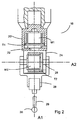
- Fig 1 illustrates a motorised scanning head mounted on a coordinate measuring machine (CMM).
- CMM coordinate measuring machine
- a workpiece 10 to be measured is mounted on a table 12 of the CMM 14 and a motorised scanning head 16 is mounted on a quill 18 of the CMM 14.
- the spindle is drivable in the directions X,Y,Z relative to the table by motors in a known manner.
- the motorised scanning head 16 comprises a fixed part formed by a base or housing 20 supported by a movable part in the form of a shaft 22 rotatable by motor M1 relative to housing 20 about an axis A1.
- the shaft 22 is secured to a further housing 24 which in turn supports a shaft 26 rotatable by a motor M2 relative to the housing 24 about an axis A2 perpendicular to the axis A1.
- a probe 28 with a stylus 29 having a workpiece contacting tip 30 is mounted onto the motorised scanning head.
- the arrangement is such that the motors M1, M2 of the head can position the workpiece contacting tip angularly about the axes A1 or A2 and the motors of the CMM can position the motorised scanning head linearly anywhere within three dimensional coordinate framework of the CMM to bring the stylus tip into a predetermined relationship with the surface being scanned.
- Linear position transducers are provided on the CMM for measuring linear displacement of the scanning head and angular position transducers T1 and T2 are provided in the scanning head for measuring angular displacement of the stylus about the respective axes A1 and A2.
- relative movement between the quill and the workpiece is obtained by enabling the quill to move in three orthogonal directions.
- relative movement between the quill (or other member on which the motorised scanning head is mounted) and the workpiece may be obtained by movement of the quill, movement of the surface on which the workpiece is mounted (e.g. the table) or a combination of the above.
- the probe has a deflectable stylus 29 and transducers in the probe measure the amount of stylus deflection.
- the probe may be two-dimensional e.g. sensing deflection in X and Y or three-dimensional e.g. sensing deflection in X,Y and Z.
- a non-contact probe may be used (e.g. an optical, capacitance or inductance probe).
- the A1 axis of the scanning head 16 is nominally parallel to the CMM Z axis (which is along the spindle 18).
- the scanning head may rotate the probe continuously about this axis.
- the A2 axis of the scanning head is orthogonal to its A1 axis.
- the motorised scanning head can position the surface sensing device in different orientations without recalibration of the head being required.
- the positions of the CMM and scanning head are controlled by a control code which is provided on a computer which may be a bespoke piece of hardware i.e. a controller or a P.C.
- the computer may be programmed to move the CMM and scanning head along measurement paths.
- a computer 15 is illustrated in Fig 1 .
- the part may be located at the edge of the working volume, thus preventing the quill of the CMM to move all the way around it.
- constraints of the part may mean access is not possible, for example when measuring a blade of a blisk (combined blade and disk), the CMM quill is constrained in some positions by the central disk and neighbouring blades.
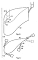
- Figs 3 and 4 illustrate a perspective and plan view respectively, of a turbine blade 32.
- access of the quill is restricted at one end of the turbine blade.
- the dashed line illustrates the boundary of possible motion of the CMM quill.
- This access problem can be overcome in traditional scanning methods by using a cranked stylus 36 on a measurement probe 38.
- the cranked stylus 36 enables the stylus tip 40 to access the part without the CMM quill moving across the boundary 34.
- it has the disadvantage that only half the turbine blade 32 can be measured with this cranked stylus 36.
- the stylus must be replaced with another cranked stylus rotated by 180°.
- a star stylus could be used.
- FIGs 5 and 6 illustrate a perspective and plan view respectively of the same turbine blade 32 as illustrated in Figs 3 and 4 .
- This turbine blade 32 is measured with a motorised scanning head on which is mounted a probe 28 with a deflectable stylus 29 and workpiece contacting tip 30.
- the angle of the head can be chosen so that the part can be measured without the quill of the CMM needing to be positioned where access is impossible.
- the head 16 is angled so that the quill of the CMM does not cross the boundary line 34.
- the angle of the head may change throughout the scan, allowing the whole profile of the part to be measured in one go.
- the head angle may be chosen so that the stylus is dragged i.e. it trails behind the head, is pushed i.e. it is ahead of the head, or is straight i.e. is aligned with the normal to the part. There may be a transition between different head angles within a measurement path. For a two-dimensional probe, it may be preferable to angle the scanning head at a low angle. This has the advantage that the deflection is primarily in the XY plane of the probe. However, for a three-dimensional probe this restriction is not required.
- FIG. 6 shows the turbine blade being scanned in a clockwise direction.
- the stylus is shown being dragged as it leaves the narrow end and pushed as it approaches the wide end.
- the head angles and quill path are adjusted to enable the stylus to follow a transition between being dragged and being pushed as it approaches the wide end.
- the stylus may be dragged as it approaches the narrow end and then pushed as it departs from the narrow end (as illustrated by the probe in dashed outline), thus avoiding the need for a transition in the head angles approaching the wide end.
- the required quill motion at the narrow end is minimised.
- considerations such as path following accuracy, throughput and working volume are taken into account.
- the information of two are needed and a third can be calculated to achieve the desired scan path. It is preferable to choose the desired position of the stylus tip and the head angle and use this data to predict the position of the CMM quill.
- coordinates of the surface sensing device in terms of position in space and orientation need to be defined. Conventionally this is done by specifying the five positions of the five drive axes (two in the head ad three in the CMM) which define the motion of the surface sensing device.
- the tip position and orientation of the surface sensing device are specified and the motion of the CMM drive axes can be derived.
- the stylus tip coordinate position to set the scan profile has the advantage that these coordinate positions are close to the desired measurements and thus it is beneficial for them to be as accurate as possible.
- it is important to keep the stylus tip in a plane for example measuring turbine blades to Civil Aviation Authority standards.
- the scanning path is chosen to avoid features such as holes.
- Defining the stylus tip coordinate positions also has the advantage that as the position of the stylus tip is known at all time (i.e. it has been defined) collisions between the stylus tip and part can be avoided.
- the head angle in determining the scan path also has advantages. For some types of probe a range of desired head angles may be required, for example a two-dimension touch probe may require angle constraints for optimum measurement. Furthermore the head may be required to be angled at certain angles to maximise access to the part.
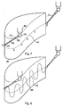
- Fig 7 is a perspective view of a turbine blade and is used to show how the scanning path is determined.
- Two parts along the desired scan path A and F are chosen.
- the stylus tip coordinate position is determined for these two points. This may be determined from CAD data or from measurements of the part.
- the head vector V which gives the direction between the stylus tip 30 and the quill 42 (either a point on the quill or the intersection of A1 and A2 angles on the head) is also chosen for points A and F. Factors which may be considered when choosing the head vector V are the type of probe being used, access restriction etc.
- the head vector V relates to the relative rotations about the A1 and A2 axes, and this data can be used interchangeably.
- the scan path may be divided up into a series of waypoints B,C,D and E.
- the stylus tip position and head vector may also be chosen for these waypoints.
- the stylus tip path can be determined from the waypoints by interpolation or fitting to a function.
- the stylus tip path can be defined by a function, such as a sinusoidal function along the surface.
- Fig 17 illustrates a scan along a straight line of length L.
- the angle about the A1 axis at the start of the scan is ⁇ .
- the change in angle about the A1 axis as the scan progresses may therefore be described by the following function in equation [1].
- ⁇ ⁇ s + ⁇ L / L ⁇ ⁇ p
- ⁇ s is the value of ⁇ at the start of the scan
- ⁇ s + ⁇ p is the desired finish angle.
- the angles ⁇ (about the A1 axis) and ⁇ (about the A2 axis) can be treated separately (i.e. different functions used relating to the two angles).
- Fig 17 illustrates the linear case, this approach is appropriate for non linear profiles.
- the vector motion can also be fitted to a predetermined equation which relates the vector motion to the features being measured.
- Fig 18 illustrates a scan of an external surface of a horizontal boss 110.
- the vector motion describes a circle, with the probe 28 kept with its longitudinal axis aligned with the surface normal.
- the motion of the head vector may also be determined by interpolation from the head angles at the waypoints.
- trajectory of the CMM quill can be determined to move (together with the scanning head) the stylus tip between A and F.
- a scanning path may likewise be determined continuously around the turbine blade of Fig 7 from point A to A, for example.
- Fig 7 illustrates a line scan 44 around the perimeter of the turbine blade 32.
- Fig 8 it is also possible to use the same method to perform a sweep scan as illustrated in Fig 8 .
- the CMM quill trajectory is determined as before for a central line 44.
- An oscillating motion is then superimposed on the head motion to produce a sweep scan.
- the motion of the CMM is complex, having non-linear trajectories and velocities.
- the motorised scanning head can be moved quickly because it has a low mass, low inertia and a high dynamic response.
- high accelerations of the CMM quill can result in machine distortion and thus create measurement errors.
- Fig 16 illustrates two possible CMM quill trajectories for scanning a path 90 between X and Y.
- the line AC shows the trajectory of the CMM quill if the scanning head angles are kept fixed between X and Y.
- the line AB shows the trajectory of the CMM quill if the scanning head angles are changed between X and Y.
- the trajectory AB has minimised and simplified the movement of the CMM quill.
- Fig 9 illustrates a traditional method of scanning a straight line of a part 48.
- the CMM quill 42 is moved in a straight line trajectory 50, dragging the probe 52 in a straight line 54.
- Fig 10 illustrates another method of scanning the straight line 54, according to the present invention.
- the motorised scanning head 16 rotates about its A1 axis whilst the CMM quill follow a locus 56 which moves backward and forwards in two back to back curves.
- movement of both the motorised scanning head and the CMM quill is used.
- movement of the motorised scanning head is maximised whilst movement of the CMM quill is minimised, thus allowing this scan to be achieved at high speed with minimum measurement errors resulting.
- this scan profile is generated by determining the desired stylus tip positions and head angles and using this data to calculate the CMM quill positions required.
- This method can be used to measure square parts very quickly. If appropriate, the stylus length and scanning head angles may be chosen to minimise movement of the CMM quill.
- Fig 15 illustrates the scan profile 80 of the internal surface of a square profile 82 taken with the quill stationary and movement provided by the scanning head.
- the stylus tip sweeps through an arc.
- the measurement data can be projected onto a plane, however in some cases it is desirable if the actual measurement data is taken on a plane. This is possible if the quill moves vertically to make the stylus tip follow straight lines.
- a square profile can be effectively measured by selecting the measurement profile of the probe (i.e. a square), selecting the head angles required during the scan (360° rotation) and thereby calculating the required movement of the CMM.
- the dashed line 81 illustrates the new stylus tip path.
- Fig 23 is a plan view of a gasket 116.
- the present invention is suitable for measuring parts such as gaskets as the stylus tip follows a defined path. In this method there is not the risk of the stylus tip following an erroneous path into a hole, as in conventional techniques in which the CMM path is chosen, rather than the stylus tip path.
- Fig 23 shows both a line path 118 and a sweep path 120 which may be used to measure the gasket 116.
- Fig 11 shows a part 58 having a recess 60 which is difficult to measure using conventional means.
- three styli 62,64,66 need to be used.
- the central portion shown between two dotted lines 68,70 can be measured using a straight stylus 62, a first cranked stylus 64 is used to measure the side and bottom portion to one side of the dotted line 68.
- the size of the cranked stylus 64 is limited by the dimensions d of the opening and it is thus limited in how much of the bottom surface it can measure.
- a second cranked stylus 66 angled 180° to the first cranked stylus 64 is used to measure the side and bottom on the side of the other dotted line 70.
- this recess 60 can be measured in a single stage as illustrated in Fig 12 .
- the stylus tip position, head angle and CMM quill position are all adjusted throughout the scan to enable all three surfaces of the recess to be measured.
- the desired stylus tip position and head angle are used to calculate the required CMM quill position.
- the CMM locus 72 followed by the quill whilst the bottom of the recess is being measured is shown.
- the example in Fig 12 illustrates access problems of complex parts, such as a blisk, for example.
- Fig 13 illustrates a boss 74 the external surface of which is to be measured.
- the quill 42 of the CMM is aligned with the centre line of the boss.
- the motorised scanning head 16 is then rotated about the A1 axis so the stylus tip 30 performs a measurement of the circumference towards the top of the boss.
- this method has the disadvantage that it cannot be repeated further down the boss, as the tip 30 will no longer be able to contact the surface.
- Fig 14 shows an alternative method for scanning a boss 74.
- the external surface of the boss 74 is divided into sections, for example four.
- the external surface of the boss 74 may be measured continuously by performing a sweep scan up one section, moving the stylus tip to the next section and then performing a sweep scan of that section down etc as shown by line 76.
- the top of the boss may also be scanned in the scan profile, for example by performing a sweep scan (not shown). As the stylus tip 30 moves from section to section, it does not leave the surface.
- the scan profile is determined as before by choosing the stylus tip position and head angles, and using these to determine the CMM quill position.
- each section could be scanned in one direction (e.g. upwards), with the stylus tip tracing the surface in the opposite direction (e.g. downwards) between sections.
- the stylus tip may leave the surface between sections.
- This method is also suitable for horizontal bosses.
- the surface profile may also be measured by taking touch points.
- the measurement probe is used to take discrete measurement positions of the surface profile.
- Fig 19 shows a bore 96 being measured by conventional techniques and Fig 20 illustrates a shallow bore 98 being measured by the method of the present invention.
- a conventional method of taking discrete measurement points of the inner surface of the bore would be to use the quill 18 to position the scanning head 16 along the centre line 100 with the stylus tip 30 below the plane 102 in which the measurement points are to be taken. The head angles are then adjusted to bring the stylus tip into contact with the surface.
- this method is not possible for a very shallow blind bore as the stylus tip cannot be positioned below the plane of the measurement points due to access restrictions.
- both the quill 18 and probe angles are moved to enable the stylus tip 30 to be brought into contact with the inner surface of the bore without the need to bring the stylus tip below the plane 102 of the measurement points. This is achieved by choosing the stylus tip path and head angles as previously described.
- the embodiments described above all describe motion using 5 axes, i.e. three linear CMM axes and two rotary scanning head axes. It may be advantageous in some cases to change from 5 axis motion to motion in which motion in one or more axis is frozen, for example using only the motion of the CMM (3 axis) or only the motion of the scanning head (2 axis).
- Fig 21 is a plan view of a turbine blade 112 shown in the XY plane.
- the path is planned to give a transition between pushing and dragging the head, which results in a smooth motion of the CMM.
- the head vector is chosen such that it remains fixed as the narrow end is scanned. This has the advantage that the resulting CMM motion is minimised. Additionally, adjustment of the head angles to keep the probe in its deflection range is not hampered by a required change in head vectors over this sharp feature.
- Fig 22 is a plan view of a turbine blade 114 shown in the XZ plane.
- the long side of the blade has a measurement path with a scanning head transition between pushing and dragging.
- the head vector is chosen so that the narrow end can be measured by motion of the scanning head only, with the CMM quill remaining stationary. This has the advantage that the quill motion is minimised for this complex feature.
- the embodiments described above are all suitable for planning a measurement path on a part. This may either be done online, for example by using a joystick to control the scanning head and CMM to thereby take discrete points on the surface having the desired stylus tip position and head angles.
- the data for these discrete points may be stored in memory and/or used to derive the measurement path of the stylus tip, scanning head and CMM quill.
- the measurement path may be planned offline, for example on a CAD model.
- the measurement profile along the surface which the stylus tip will follow and the head angles are selected on the CAD model.
- This data is stored in memory and/or used to derive the measurement path of the stylus tip, scanning head and CMM quill.
- the measurement path data is converted into command code which sends position demand codes to the CMM and scanning head to follow the desired measurement paths when measuring a part.
- the probe During the measurement of the part, the probe must be kept within its deflection range (and non contact probes must be kept within their working range). This is achieved by deviating the scanning head from its prescribed motion.
- the scanning head is servoed along a target vector to maintain the probe within its range.
- this target vector is normal to the surface. However, factors such as the orientation of the probe, friction or the requirement to stay on a required profile may cause a different target vector to be chosen. Calculated tip position, historic surface points used to project forwards etc may be used to determine the target vector.
- the CMM quill path may be modified to keep the stylus tip in a defined plane. For example, if the head angle is servoed to keep the probe within its deflection range, the stylus tip may move away from the defined surface plane of the measurement path. The change in stylus position is used to determine the distance the stylus tip has moved off plane and the CMM can be driven accordingly to bring the stylus tip back on plane.
- a contact probe these scanning methods are also suitable for use with a non-contact probe, for example an optical, inductance or capacitance probe.
- a non-contact probe for example an optical, inductance or capacitance probe.
- the light spot on the surface may be treated as equivalent to the stylus tip position, for example.
- an offset may be treated as equivalent to the stylus tip position.
- the stylus tip is effectively a pivot point about which the probe may be orientated and still measure the same coordinate position.
Landscapes
- Physics & Mathematics (AREA)
- General Physics & Mathematics (AREA)
- A Measuring Device Byusing Mechanical Method (AREA)
- Length Measuring Devices With Unspecified Measuring Means (AREA)
- Machine Tool Sensing Apparatuses (AREA)
- Multi-Process Working Machines And Systems (AREA)
- Numerical Control (AREA)
Claims (20)
- Verfahren zum Vermessen einer Oberfläche unter Verwendung einer Oberflächenerfassungsvorrichtung, die an einem Abtastkopf an einem Element einer Koordinatenpositionierungsvorrichtung montiert ist, wobei die Koordinatenpositionierungsvorrichtung betrieben werden kann, um eine relative Bewegung zwischen dem Abtastkopf und dem Oberflächenprofil zu erzeugen, und wobei der Abtastkopf einen Antrieb zur Erzeugung einer Rotationsbewegung der Oberflächenerfassungsvorrichtung um eine oder mehrere Achsen aufweist, wobei das Verfahren die folgenden Schritte umfasst, dass:(a) das gewünschte Messprofil an der Oberfläche definiert wird, dem die Oberflächenerfassungsvorrichtung nachfolgt;(b) die gewünschte Bewegung der Orientierung der Oberflächenerfassungsvorrichtung definiert wird, wenn die Oberflächenerfassungsvorrichtung dem Messprofil von Schritt (a) folgt;(c) die bei den Schritten (a) und (b) bestimmten Daten dazu verwendet werden, den erforderlichen Pfad der relativen Bewegung zwischen dem Element der Koordinatenpositionierungsvorrichtung und der Oberfläche abzuleiten, so dass die Oberflächenerfassungsvorrichtung eine Trajektorie entlang des Messprofils vorschreibt; dadurch gekennzeichnet, dassdie Bewegung der Orientierung bei Schritt (b) derart ist, dass die Orientierung relativ zu der Oberflächennormalen variiert.
- Verfahren nach Anspruch 1,
wobei das Messprofil der Oberflächenerfassungsvorrichtung linear ist. - Verfahren nach Anspruch 1,
wobei das Messprofil der Oberflächenerfassungsvorrichtung nicht linear ist. - Verfahren nach einem der Ansprüche 1 bis 3,
wobei die Bewegung der Orientierung bei Schritt (b) eine Funktion umfasst, die die Orientierung während der Bewegung der Oberflächenerfassungsvorrichtung entlang des Messprofils bestimmt. - Verfahren nach einem der Ansprüche 1 bis 3,
wobei die Bewegung der Orientierung bei Schritt (b) durch Definition der Orientierung an diskreten Punkten entlang des Messprofils und Interpolieren zwischen diesen bestimmt wird. - Verfahren nach einem der Ansprüche 1 bis 5,
wobei die Orientierung bei Schritt (b) so gewählt ist, um die Oberflächenerfassungsvorrichtung derart zu positionieren, dass sie dem Kopf nachläuft oder vor dem Kopf hergetrieben wird. - Verfahren nach Anspruch 6,
wobei ein Übergang von einem derartigen Typ von Orientierung zu einem anderen vorgesehen wird. - Verfahren nach einem der vorhergehenden Ansprüche,
wobei der Messpfad bei Schritt (a) und die Bewegung der Orientierung bei Schritt (b) derart gewählt sind, um eine gewünschte relative Bewegung zwischen dem Element der Koordinatenpositionierungsvorrichtung und der Oberfläche bereitzustellen. - Verfahren nach einem der vorhergehenden Ansprüche,
wobei das Messprofil von Schritt (a) durch Bestimmung von zwei oder mehreren diskreten Messpunkten an dem Oberflächenprofil bestimmt wird. - Verfahren nach einem der Ansprüche 1 bis 8,
wobei das Messprofil von Schritt (a) durch eine Funktion definiert ist. - Verfahren nach einem der vorhergehenden Ansprüche,
wobei eine Bewegung in zumindest einer Achse während einem Teil des Messprofils fixiert werden kann. - Verfahren nach Anspruch 11,
wobei die Bewegung des Abtastkopfes während eines Teils des Messprofils fixiert wird. - Verfahren nach Anspruch 11,
wobei die Bewegung der Koordinatenpositionierungsmaschine während eines Teils des Messprofils fixiert wird. - Verfahren nach einem der vorhergehenden Ansprüche,
mit dem Schritt, dass die Daten von den Schritten (a), (b) und (c) verwendet werden, um eine Oberfläche zu vermessen. - Verfahren nach Anspruch 14,
wobei eine Rotationsbewegung um zumindest eine Achse des Abtastkopfes dazu verwendet wird, die Oberflächenerfassungsvorrichtung in ihrem Messbereich zu halten. - Verfahren nach Anspruch 15,
wobei der Abtastkopf entlang eines Zielvektors verstellt wird, um die Oberflächenerfassungsvorrichtung innerhalb ihres Messbereichs zu halten. - Verfahren nach einem der Ansprüche 14 bis 16,
wobei die relative Bewegung zwischen dem Element der Koordinatenpositionierungsvorrichtung und der Oberfläche dazu verwendet wird, die Oberflächenerfassungsvorrichtung so beizubehalten, dass sie entlang einer gewünschten Ebene der Oberfläche nachfährt. - Computerprogramm zum Programmieren eines Messpfades für eine Oberflächenerfassungsvorrichtung, die an einem Abtastkopf an einem Element einer Koordinatenpositionierungsvorrichtung montiert ist, wobei die Koordinatenpositionierungsvorrichtung derart betrieben werden kann, um eine relative Bewegung zwischen dem Abtastkopf und dem Oberflächenprofil zu erzeugen, und wobei der Abtastkopf einen Antrieb zur Erzeugung einer Rotationsbewegung der Oberflächenerfassungsvorrichtung um eine oder mehrere Achsen aufweist, wobei das Computerprogramm Code umfasst, der derart angepasst ist, um die Schritte nach einem der Ansprüche 1 bis 17 auszuführen, wenn er an einem Computer ausgeführt wird.
- Vorrichtung zum Vermessen eines Oberflächenprofils unter Verwendung einer Oberflächenerfassungsvorrichtung (29), die an einem Abtastkopf (16) an einem Element (18) einer Koordinatenpositionierungsvorrichtung (14) montiert ist, wobei die Koordinatenpositionierungsvorrichtung (14) derart betrieben werden kann, um eine relative Bewegung zwischen dem Abtastkopf (16) und dem Oberflächenprofil zu erzeugen, und wobei der Abtastkopf (16) einen Antrieb (M1, M2) zur Erzeugung einer Rotationsbewegung der Oberflächenerfassungsvorrichtung (29) um eine oder mehrere Achsen (A1, A2) auf weist, wobei die Vorrichtung einen Computer (15) zur Ausführung der folgenden Schritte umfasst, dass:(a) das gewünschte Messprofil an der Oberfläche definiert wird, dem die Oberflächenerfassungsvorrichtung (29) folgt;(b) die gewünschte Bewegung der Orientierung der Oberflächenerfassungsvorrichtung (29) definiert wird, wenn die Oberflächenerfassungsvorrichtung (29) dem Messprofil von Schritt (a) folgt;(c) die bei den Schritten (a) und (b) bestimmten Daten dazu verwendet werden, den erforderlichen Pfad der relativen Bewegung zwischen dem Element (18) der Koordinatenpositionierungsvorrichtung (14) und der Oberfläche abzuleiten, so dass die Oberflächenerfassungsvorrichtung (29) eine Trajektorie entlang des Messprofils vorschreibt;dadurch gekennzeichnet, dass
die Bewegung der Orientierung bei Schritt (b) derart ist, dass die Orientierung relativ zu der Oberflächennormalen variiert. - Vorrichtung nach Anspruch 19,
mit dem Schritt, dass die Daten der Schritte (a), (b) und (c) dazu verwendet werden, eine Oberfläche zu vermessen.
Applications Claiming Priority (2)
| Application Number | Priority Date | Filing Date | Title |
|---|---|---|---|
| GBGB0605796.2A GB0605796D0 (en) | 2006-03-23 | 2006-03-23 | Apparatus and method of measuring workpieces |
| PCT/GB2007/001064 WO2007107776A1 (en) | 2006-03-23 | 2007-03-23 | Apparatus and method of measuring workpieces |
Publications (2)
| Publication Number | Publication Date |
|---|---|
| EP2002206A1 EP2002206A1 (de) | 2008-12-17 |
| EP2002206B1 true EP2002206B1 (de) | 2010-05-12 |
Family
ID=36384003
Family Applications (2)
| Application Number | Title | Priority Date | Filing Date |
|---|---|---|---|
| EP07732130.5A Active EP2002207B2 (de) | 2006-03-23 | 2007-03-23 | Vorrichtung und verfahren zum vermessen von werkstücken |
| EP07732126A Active EP2002206B1 (de) | 2006-03-23 | 2007-03-23 | Vorrichtung und verfahren zur messung von werkstücken |
Family Applications Before (1)
| Application Number | Title | Priority Date | Filing Date |
|---|---|---|---|
| EP07732130.5A Active EP2002207B2 (de) | 2006-03-23 | 2007-03-23 | Vorrichtung und verfahren zum vermessen von werkstücken |
Country Status (8)
| Country | Link |
|---|---|
| US (3) | US7971365B2 (de) |
| EP (2) | EP2002207B2 (de) |
| JP (2) | JP2009531185A (de) |
| CN (2) | CN101405563B (de) |
| AT (2) | ATE467812T1 (de) |
| DE (2) | DE602007005234D1 (de) |
| GB (1) | GB0605796D0 (de) |
| WO (2) | WO2007107777A1 (de) |
Families Citing this family (67)
| Publication number | Priority date | Publication date | Assignee | Title |
|---|---|---|---|---|
| GB0605796D0 (en) * | 2006-03-23 | 2006-05-03 | Renishaw Plc | Apparatus and method of measuring workpieces |
| EP2064514B2 (de) * | 2006-09-05 | 2014-08-06 | Renishaw PLC | Oberflächenmessgerät |
| DE102006055005A1 (de) * | 2006-11-17 | 2008-05-29 | Carl Zeiss Industrielle Messtechnik Gmbh | Verfahren und Vorrichtung zum Bestimmen von Raumkoordinaten an einer Vielzahl von Messpunkten |
| TWI317418B (en) * | 2007-03-01 | 2009-11-21 | Fu Kue Chang | A measuring method for the surface of a propeller |
| EP1978328B1 (de) * | 2007-04-03 | 2015-02-18 | Hexagon Metrology AB | Oszillierende Rastersonde mit konstanter Kontaktkraft |
| GB0707720D0 (en) * | 2007-04-23 | 2007-05-30 | Renishaw Plc | Apparatus and method for controlling or programming a measurement routine |
| GB0707921D0 (en) | 2007-04-24 | 2007-05-30 | Renishaw Plc | Apparatus and method for surface measurement |
| JP5312032B2 (ja) * | 2007-06-29 | 2013-10-09 | 株式会社東京精密 | 表面形状測定装置及び表面形状測定方法 |
| GB0716218D0 (en) | 2007-08-20 | 2007-09-26 | Renishaw Plc | Measurement path generation |
| SE533198C2 (sv) * | 2008-02-14 | 2010-07-20 | Hexagon Metrology Ab | Mätanordning med mäthuvud för kontrollmätning av föremål |
| JP5645349B2 (ja) * | 2008-03-24 | 2014-12-24 | キヤノン株式会社 | 形状測定装置 |
| US9689655B2 (en) | 2008-10-29 | 2017-06-27 | Renishaw Plc | Measurement method |
| DE102008061444B4 (de) * | 2008-12-10 | 2014-07-03 | Mag Ias Gmbh | Drehmaschine mit einer Messvorrichtung und Verfahren zum Vermessen eines Werkstückes auf solch einer Drehmaschine |
| DE102009008722A1 (de) * | 2009-02-06 | 2010-08-19 | Carl Zeiss Industrielle Messtechnik Gmbh | Koordinatenmessgerät zum Bestimmen von Raumkoordinaten an einem Messobjekt sowie ein Tastkopfsystem für ein solches Koordinatenmessgerät |
| JP5277033B2 (ja) * | 2009-03-25 | 2013-08-28 | 株式会社ミツトヨ | 補正ボール径算出方法および形状測定装置 |
| CH701868B1 (fr) * | 2009-09-07 | 2015-01-15 | Tesa Sa | Machine à mesurer des coordonnées motorisée à programmation manuelle et méthode de contrôle d'une telle machine. |
| DE102009049534A1 (de) * | 2009-10-06 | 2011-04-07 | Carl Zeiss Industrielle Messtechnik Gmbh | Koordinatenmessgerät mit Lageänderungssensoren |
| JP5763419B2 (ja) * | 2011-05-27 | 2015-08-12 | 株式会社ミツトヨ | 断面形状測定方法 |
| RU2466350C1 (ru) * | 2011-06-20 | 2012-11-10 | Федеральное государственное бюджетное образовательное учреждение высшего профессионального образования "Казанский национальный исследовательский технический университет им. А.Н. Туполева-КАИ" (КНИТУ-КАИ) | Способ контроля геометрических параметров заготовки лопаток газотурбинных двигателей и устройство для его осуществления |
| US8631577B2 (en) | 2011-07-22 | 2014-01-21 | Pratt & Whitney Canada Corp. | Method of fabricating integrally bladed rotor and stator vane assembly |
| US9995574B2 (en) * | 2011-08-11 | 2018-06-12 | Mitutoyo Corporation | CMM moving path adjustment assisting method and apparatus |
| JP6199870B2 (ja) * | 2011-10-06 | 2017-09-20 | レニショウ パブリック リミテッド カンパニーRenishaw Public Limited Company | 測定方法 |
| CN102564372A (zh) * | 2011-12-16 | 2012-07-11 | 西北工业大学 | 一种航空发动机叶片误差分离方法 |
| CN102538643A (zh) * | 2011-12-29 | 2012-07-04 | 无锡曙光模具有限公司 | 叶片轮廓度检测装置 |
| US9043011B2 (en) * | 2012-01-04 | 2015-05-26 | General Electric Company | Robotic machining apparatus method and system for turbine buckets |
| EP2624088B1 (de) | 2012-02-03 | 2019-12-18 | Mitutoyo Corporation | Hilfsverfahren und -vorrichtung zur Anpassung des Koordinatenmessmaschinenbewegungsweges |
| EP2636857A1 (de) * | 2012-03-07 | 2013-09-11 | Siemens Aktiengesellschaft | System zum Prüfen der Schaufeln einer Turbomaschine |
| DE102012205599A1 (de) * | 2012-04-04 | 2013-10-10 | Carl Zeiss Industrielle Messtechnik Gmbh | Reduzieren von Fehlern einer Drehvorrichtung bei der Bestimmung von Koordinaten eines Werkstücks oder bei der Bearbeitung eines Werkstücks |
| CN102768026B (zh) * | 2012-07-23 | 2015-07-29 | 黑龙江科技大学 | 一种叶片全尺寸快速检测的设备 |
| US8966775B2 (en) * | 2012-10-09 | 2015-03-03 | Nike, Inc. | Digital bite line creation for shoe assembly |
| CN102980491B (zh) * | 2012-11-16 | 2016-08-24 | 无锡麦铁精密机械制造有限公司 | 一种弧面轮廓度检具 |
| CN103084926A (zh) * | 2013-01-14 | 2013-05-08 | 长治市中瑞精密轴承制造有限公司 | 工件内外径实时测量装置 |
| EP2954285B1 (de) * | 2013-02-05 | 2022-04-06 | Renishaw Plc. | Verfahren und vorrichtung zur messung eines teils |
| US8995008B2 (en) * | 2013-03-13 | 2015-03-31 | Konica Minolta Laboratory U.S.A. | System and method for adjusting an image to be printed on a medium that will be embossed |
| CN105378425B (zh) * | 2013-07-09 | 2019-07-26 | 福特全球技术公司 | 利用尺寸数据来表征表面的系统和方法 |
| CN103692292B (zh) * | 2013-11-25 | 2016-08-17 | 湖北三江航天险峰电子信息有限公司 | 在车床上进行工件尺寸在线测量的方法 |
| US9639083B2 (en) | 2013-12-18 | 2017-05-02 | Mitutoyo Corporation | System and method for programming workpiece feature inspection operations for a coordinate measuring machine |
| WO2015138529A1 (en) | 2014-03-11 | 2015-09-17 | Ametek Precitech, Inc. | Edge treatment process |
| DE102014108629A1 (de) * | 2014-06-18 | 2015-12-24 | Brötje-Automation GmbH | Fertigungssystem |
| US9417047B2 (en) | 2014-08-11 | 2016-08-16 | Toyota Motor Engineering & Manufacturing North America, Inc. | Three-dimensional edge profile determination |
| DE102014113663A1 (de) | 2014-09-22 | 2016-03-24 | Broetje-Automation Gmbh | Bearbeitungsanlage für Flugzeugstrukturbauteile |
| DE202015104273U1 (de) | 2015-08-13 | 2016-11-15 | Brötje-Automation GmbH | Bearbeitungsstation |
| CA2939029A1 (en) * | 2015-08-21 | 2017-02-21 | Williams & White Machine Inc. | Feed finger positioning apparatus and methods |
| JP6206527B2 (ja) * | 2016-03-16 | 2017-10-04 | 横浜ゴム株式会社 | 円形部材の内周長測定装置 |
| US11162914B2 (en) * | 2016-06-30 | 2021-11-02 | Kitz Corporation | Pressure-resistance inspection apparatus for valves and its inspection method, and hydrogen gas detection unit |
| GB2554057B (en) * | 2016-07-25 | 2022-04-06 | Ele Advanced Tech Limited | A method of measuring the wall thickness of an article and an apparatus for making such measurements |
| GB201700534D0 (en) * | 2017-01-12 | 2017-03-01 | Rolls Royce Plc | A method of measuring fan blade picture frame width |
| US10408091B2 (en) | 2017-03-31 | 2019-09-10 | General Electric Company | Mounting apparatuses secured to turbine airfoils of turbine systems |
| DE102017222132B4 (de) * | 2017-12-07 | 2019-07-04 | Carl Zeiss Industrielle Messtechnik Gmbh | Sensor für ein Koordinatenmessgerät |
| EP3531062A1 (de) | 2018-02-26 | 2019-08-28 | Renishaw PLC | Koordinatenpositionierungsmaschine |
| CN108917689B (zh) * | 2018-08-01 | 2021-01-22 | 京东方科技集团股份有限公司 | 曲率半径测量设备及其测量方法 |
| US10760889B2 (en) * | 2018-09-12 | 2020-09-01 | United Technologies Corporation | Fan blade masking/coating check inspection tool |
| CN109238185B (zh) * | 2018-09-30 | 2023-06-09 | 江苏省水利科学研究院 | 一种桥墩安全性实时监测系统及监测方法 |
| CN109443290B (zh) * | 2018-12-25 | 2020-08-21 | 中国航发哈尔滨轴承有限公司 | 一种测量轴承三瓣波外滚道波形尺寸的方法 |
| CN109926871A (zh) * | 2019-03-21 | 2019-06-25 | 苏州山德精密工具有限公司 | 自带螺旋内冷水孔圆棒的导正方法 |
| FR3095507B1 (fr) * | 2019-04-29 | 2021-04-16 | Safran Aircraft Engines | Procede de controle dimensionnel d’une piece de turbomachine |
| GB202002562D0 (en) * | 2020-02-24 | 2020-04-08 | Renishaw Plc | Measurement method |
| DE102020111146B4 (de) | 2020-04-23 | 2025-10-30 | Carl Zeiss Industrielle Messtechnik Gmbh | Verfahren und Vorrichtung zum Bestimmen von dimensionalen und/oder geometrischen Eigenschaften eines Messobjekts |
| GB202018028D0 (en) | 2020-11-17 | 2020-12-30 | Rolls Royce Plc | Method of inspecting a component |
| DE102020133454B3 (de) | 2020-12-15 | 2022-06-02 | AUDI HUNGARIA Zrt. | Verfahren zur 3D-Positionsmessung eines Gewindes |
| US11740063B2 (en) * | 2021-05-25 | 2023-08-29 | Hexagon Metrology, Inc. | Post-processing of measurement data collected with optical probe |
| CN114343641A (zh) * | 2022-01-24 | 2022-04-15 | 广州熠华教育咨询服务有限公司 | 一种学习困难干预训练指导方法及其系统 |
| WO2024048647A1 (ja) * | 2022-08-31 | 2024-03-07 | 株式会社ワコム | 電子ペンの評価方法及び評価システム |
| KR102841244B1 (ko) * | 2023-04-21 | 2025-08-01 | 주식회사 에스코넥 | 곡면 형상 검사 장치 |
| CN117537736A (zh) * | 2023-10-26 | 2024-02-09 | 中国航发沈阳黎明航空发动机有限责任公司 | 一种高压双层整体叶盘叶型测量方法 |
| CN117532505A (zh) * | 2023-11-15 | 2024-02-09 | 上海赛威德机器人有限公司 | 基于液控浮动打磨头的焊缝形貌检测方法 |
| CN121112891B (zh) * | 2025-09-11 | 2026-04-03 | 苏州融壹士信息科技有限公司 | 一种物料自动化输送测量系统 |
Family Cites Families (44)
| Publication number | Priority date | Publication date | Assignee | Title |
|---|---|---|---|---|
| GB1123344A (en) * | 1964-08-25 | 1968-08-14 | Edward John Roe | Improved centring device or like fine movement indicator |
| US3531868A (en) | 1968-04-18 | 1970-10-06 | Ford Motor Co | Surface scanner for measuring the coordinates of points on a three-dimensional surface |
| US4485453A (en) * | 1982-03-29 | 1984-11-27 | International Business Machines Corporation | Device and method for determining the location and orientation of a drillhole |
| US4631834A (en) * | 1984-04-20 | 1986-12-30 | Mitutuoyo Mfg. Co., Ltd. | Coordinate measuring instrument |
| GB8508391D0 (en) * | 1985-03-30 | 1985-05-09 | Ae Plc | Measurement of engineering components |
| JPS63206607A (ja) | 1987-02-23 | 1988-08-25 | Mitsutoyo Corp | 三次元測定機 |
| DE3740070A1 (de) * | 1987-11-26 | 1989-06-08 | Zeiss Carl Fa | Dreh-schwenk-einrichtung fuer tastkoepfe von koordinatenmessgeraeten |
| GB8729638D0 (en) * | 1987-12-19 | 1988-02-03 | Renishaw Plc | Mounting for surface sensing device |
| US5189806A (en) * | 1988-12-19 | 1993-03-02 | Renishaw Plc | Method of and apparatus for scanning the surface of a workpiece |
| GB8908854D0 (en) * | 1989-04-19 | 1989-06-07 | Renishaw Plc | Method of and apparatus for scanning the surface of a workpiece |
| DE4026942A1 (de) * | 1990-08-25 | 1992-02-27 | Zeiss Carl Fa | Verfahren zur beruehrungslosen vermessung von objektoberflaechen |
| US5251156A (en) | 1990-08-25 | 1993-10-05 | Carl-Zeiss-Stiftung, Heidenheim/Brenz | Method and apparatus for non-contact measurement of object surfaces |
| JP2630119B2 (ja) | 1991-07-11 | 1997-07-16 | 松下電器産業株式会社 | 電圧設定装置 |
| JP2538339Y2 (ja) * | 1991-08-30 | 1997-06-11 | ぺんてる株式会社 | 球面作業ロボット装置 |
| JPH06185910A (ja) * | 1992-12-17 | 1994-07-08 | Enshu Ltd | 三次元測定用のタッチプローブ装置 |
| JPH07286846A (ja) * | 1994-04-20 | 1995-10-31 | Tokyo Seimitsu Co Ltd | 不連続部分を有する表面の形状測定方法及び形状測定装置 |
| JPH0835973A (ja) * | 1994-07-21 | 1996-02-06 | Olympus Optical Co Ltd | 走査型プローブ顕微鏡 |
| GB9612383D0 (en) * | 1995-12-07 | 1996-08-14 | Rank Taylor Hobson Ltd | Surface form measurement |
| DE59711570D1 (de) | 1996-12-21 | 2004-06-03 | Zeiss Carl | Verfahren zur Steuerung eines Koordinatenmessgerätes und Koordinatenmessgerät |
| DE19712029A1 (de) | 1997-03-21 | 1998-09-24 | Zeiss Carl Fa | Verfahren zur Steuerung von Koordinatenmeßgeräten nach Solldaten |
| JP3439331B2 (ja) * | 1997-09-12 | 2003-08-25 | 株式会社ミツトヨ | プローブ座標系駆動装置 |
| US6251156B1 (en) * | 1998-10-30 | 2001-06-26 | Midrex Technologies, Inc. | Method of producing molten iron in duplex furnaces |
| DE10035714B4 (de) * | 1999-07-23 | 2011-06-09 | Mitutoyo Corp. | Oberflächengestalt-Messverfahren |
| JP2001249067A (ja) * | 2000-01-18 | 2001-09-14 | Internatl Business Mach Corp <Ibm> | 走査型プローブ顕微鏡を用いて輪郭走査を実行する装置および方法 |
| DE10006753A1 (de) * | 2000-02-15 | 2001-08-16 | Zeiss Carl | Dreh-Schwenkeinrichtung für den Tastkopf eines Koordinatenmeßgerätes |
| DE50115041D1 (de) | 2000-05-23 | 2009-09-24 | Zeiss Ind Messtechnik Gmbh | Korrekturverfahren für Koordinatenmessgeräte |
| WO2003008900A1 (de) * | 2001-07-16 | 2003-01-30 | Werth Messtechnik Gmbh | Verfahren zum scannenden messen einer oberflächenkontur |
| GB0126232D0 (en) | 2001-11-01 | 2002-01-02 | Renishaw Plc | Calibration of an analogue probe |
| GB0210990D0 (en) | 2002-05-14 | 2002-06-19 | Rolls Royce Plc | Method of generating an inspection program and method of generating a visual display |
| GB0215152D0 (en) * | 2002-07-01 | 2002-08-07 | Renishaw Plc | Probe or stylus orientation |
| GB0220158D0 (en) * | 2002-08-30 | 2002-10-09 | Renishaw Plc | Method of scanning |
| GB0228371D0 (en) * | 2002-12-05 | 2003-01-08 | Leland E C E | Workpiece inspection method |
| US7543393B2 (en) * | 2003-12-16 | 2009-06-09 | Renishaw Plc | Method of calibrating a scanning system |
| JP2005214727A (ja) * | 2004-01-28 | 2005-08-11 | Olympus Corp | 測定用プローブおよびこれを用いた形状測定機 |
| US20080021672A1 (en) * | 2004-03-18 | 2008-01-24 | Renishaw Plc | Scanning an Object |
| US20070247639A1 (en) † | 2004-05-10 | 2007-10-25 | Koninklijke Philips Electronics, N.V. | Device and Method for Optical Precision Measurement |
| JP4197662B2 (ja) * | 2004-05-28 | 2008-12-17 | Tdk株式会社 | 記録再生試験装置 |
| JP4582446B2 (ja) * | 2004-11-18 | 2010-11-17 | 株式会社東京精密 | 測定装置 |
| GB0508273D0 (en) * | 2005-04-25 | 2005-06-01 | Renishaw Plc | Method for scanning the surface of a workpiece |
| GB0508217D0 (en) * | 2005-04-25 | 2005-06-01 | Renishaw Plc | Method for scanning the surface of a workpiece |
| GB0605796D0 (en) * | 2006-03-23 | 2006-05-03 | Renishaw Plc | Apparatus and method of measuring workpieces |
| EP1983297B1 (de) * | 2007-04-18 | 2010-04-07 | Hexagon Metrology AB | Tastkopf mit konstanter Rastergeschwindigkeit |
| GB0707921D0 (en) * | 2007-04-24 | 2007-05-30 | Renishaw Plc | Apparatus and method for surface measurement |
| EP1988357B1 (de) * | 2007-05-04 | 2018-10-17 | Hexagon Technology Center GmbH | Verfahren und Vorrichtung zur Koordinatenmessung |
-
2006
- 2006-03-23 GB GBGB0605796.2A patent/GB0605796D0/en not_active Ceased
-
2007
- 2007-03-23 DE DE602007005234T patent/DE602007005234D1/de active Active
- 2007-03-23 US US12/224,657 patent/US7971365B2/en not_active Expired - Fee Related
- 2007-03-23 DE DE602007006458T patent/DE602007006458D1/de active Active
- 2007-03-23 AT AT07732126T patent/ATE467812T1/de not_active IP Right Cessation
- 2007-03-23 JP JP2009502195A patent/JP2009531185A/ja active Pending
- 2007-03-23 US US12/224,654 patent/US7809523B2/en active Active
- 2007-03-23 AT AT07732130T patent/ATE460642T1/de not_active IP Right Cessation
- 2007-03-23 WO PCT/GB2007/001068 patent/WO2007107777A1/en not_active Ceased
- 2007-03-23 EP EP07732130.5A patent/EP2002207B2/de active Active
- 2007-03-23 CN CN2007800100120A patent/CN101405563B/zh active Active
- 2007-03-23 JP JP2009502193A patent/JP5350216B2/ja active Active
- 2007-03-23 EP EP07732126A patent/EP2002206B1/de active Active
- 2007-03-23 WO PCT/GB2007/001064 patent/WO2007107776A1/en not_active Ceased
- 2007-03-23 CN CN200780010102XA patent/CN101405564B/zh active Active
-
2011
- 2011-05-25 US US13/067,344 patent/US8302321B2/en active Active
Also Published As
| Publication number | Publication date |
|---|---|
| US20120060385A1 (en) | 2012-03-15 |
| US20090030648A1 (en) | 2009-01-29 |
| EP2002207A1 (de) | 2008-12-17 |
| CN101405563A (zh) | 2009-04-08 |
| US20100011600A1 (en) | 2010-01-21 |
| EP2002207B1 (de) | 2010-03-10 |
| US7809523B2 (en) | 2010-10-05 |
| DE602007005234D1 (de) | 2010-04-22 |
| WO2007107777A1 (en) | 2007-09-27 |
| GB0605796D0 (en) | 2006-05-03 |
| JP5350216B2 (ja) | 2013-11-27 |
| ATE467812T1 (de) | 2010-05-15 |
| EP2002206A1 (de) | 2008-12-17 |
| US8302321B2 (en) | 2012-11-06 |
| CN101405563B (zh) | 2013-02-20 |
| CN101405564B (zh) | 2013-04-24 |
| ATE460642T1 (de) | 2010-03-15 |
| CN101405564A (zh) | 2009-04-08 |
| US7971365B2 (en) | 2011-07-05 |
| JP2009531185A (ja) | 2009-09-03 |
| EP2002207B2 (de) | 2017-04-12 |
| DE602007006458D1 (de) | 2010-06-24 |
| JP2009531695A (ja) | 2009-09-03 |
| WO2007107776A1 (en) | 2007-09-27 |
Similar Documents
| Publication | Publication Date | Title |
|---|---|---|
| EP2002206B1 (de) | Vorrichtung und verfahren zur messung von werkstücken | |
| JP5665270B2 (ja) | 工作物の表面を走査する方法 | |
| EP2140318B1 (de) | Vorrichtung und verfahren zur steuerung oder programmierung eines messpfads | |
| US7676942B2 (en) | Multi-axis positioning and measuring system and method of using | |
| US8825438B2 (en) | Course of motion determination | |
| EP2140225B2 (de) | Vorrichtung und verfahren zur oberflächenmessung | |
| EP1983297B1 (de) | Tastkopf mit konstanter Rastergeschwindigkeit | |
| JP2007529734A (ja) | 物体走査 | |
| CN109782815A (zh) | 基于多轴联动系统的复杂型面自适应测量路径规划方法 | |
| JP2020056637A (ja) | 形状測定装置の制御方法 | |
| CN1934409B (zh) | 物体扫描 | |
| CN120685035A (zh) | 测量系统 |
Legal Events
| Date | Code | Title | Description |
|---|---|---|---|
| PUAI | Public reference made under article 153(3) epc to a published international application that has entered the european phase |
Free format text: ORIGINAL CODE: 0009012 |
|
| 17P | Request for examination filed |
Effective date: 20081021 |
|
| AK | Designated contracting states |
Kind code of ref document: A1 Designated state(s): AT BE BG CH CY CZ DE DK EE ES FI FR GB GR HU IE IS IT LI LT LU LV MC MT NL PL PT RO SE SI SK TR |
|
| 17Q | First examination report despatched |
Effective date: 20090225 |
|
| GRAP | Despatch of communication of intention to grant a patent |
Free format text: ORIGINAL CODE: EPIDOSNIGR1 |
|
| DAX | Request for extension of the european patent (deleted) | ||
| GRAS | Grant fee paid |
Free format text: ORIGINAL CODE: EPIDOSNIGR3 |
|
| GRAA | (expected) grant |
Free format text: ORIGINAL CODE: 0009210 |
|
| AK | Designated contracting states |
Kind code of ref document: B1 Designated state(s): AT BE BG CH CY CZ DE DK EE ES FI FR GB GR HU IE IS IT LI LT LU LV MC MT NL PL PT RO SE SI SK TR |
|
| REG | Reference to a national code |
Ref country code: GB Ref legal event code: FG4D |
|
| REG | Reference to a national code |
Ref country code: CH Ref legal event code: EP |
|
| REG | Reference to a national code |
Ref country code: CH Ref legal event code: NV Representative=s name: KIRKER & CIE S.A. |
|
| REG | Reference to a national code |
Ref country code: IE Ref legal event code: FG4D |
|
| REF | Corresponds to: |
Ref document number: 602007006458 Country of ref document: DE Date of ref document: 20100624 Kind code of ref document: P |
|
| REG | Reference to a national code |
Ref country code: NL Ref legal event code: VDEP Effective date: 20100512 |
|
| LTIE | Lt: invalidation of european patent or patent extension |
Effective date: 20100512 |
|
| PG25 | Lapsed in a contracting state [announced via postgrant information from national office to epo] |
Ref country code: LT Free format text: LAPSE BECAUSE OF FAILURE TO SUBMIT A TRANSLATION OF THE DESCRIPTION OR TO PAY THE FEE WITHIN THE PRESCRIBED TIME-LIMIT Effective date: 20100512 Ref country code: NL Free format text: LAPSE BECAUSE OF FAILURE TO SUBMIT A TRANSLATION OF THE DESCRIPTION OR TO PAY THE FEE WITHIN THE PRESCRIBED TIME-LIMIT Effective date: 20100512 Ref country code: SE Free format text: LAPSE BECAUSE OF FAILURE TO SUBMIT A TRANSLATION OF THE DESCRIPTION OR TO PAY THE FEE WITHIN THE PRESCRIBED TIME-LIMIT Effective date: 20100512 Ref country code: ES Free format text: LAPSE BECAUSE OF FAILURE TO SUBMIT A TRANSLATION OF THE DESCRIPTION OR TO PAY THE FEE WITHIN THE PRESCRIBED TIME-LIMIT Effective date: 20100823 |
|
| PG25 | Lapsed in a contracting state [announced via postgrant information from national office to epo] |
Ref country code: AT Free format text: LAPSE BECAUSE OF FAILURE TO SUBMIT A TRANSLATION OF THE DESCRIPTION OR TO PAY THE FEE WITHIN THE PRESCRIBED TIME-LIMIT Effective date: 20100512 Ref country code: FI Free format text: LAPSE BECAUSE OF FAILURE TO SUBMIT A TRANSLATION OF THE DESCRIPTION OR TO PAY THE FEE WITHIN THE PRESCRIBED TIME-LIMIT Effective date: 20100512 Ref country code: IS Free format text: LAPSE BECAUSE OF FAILURE TO SUBMIT A TRANSLATION OF THE DESCRIPTION OR TO PAY THE FEE WITHIN THE PRESCRIBED TIME-LIMIT Effective date: 20100912 Ref country code: LV Free format text: LAPSE BECAUSE OF FAILURE TO SUBMIT A TRANSLATION OF THE DESCRIPTION OR TO PAY THE FEE WITHIN THE PRESCRIBED TIME-LIMIT Effective date: 20100512 Ref country code: SI Free format text: LAPSE BECAUSE OF FAILURE TO SUBMIT A TRANSLATION OF THE DESCRIPTION OR TO PAY THE FEE WITHIN THE PRESCRIBED TIME-LIMIT Effective date: 20100512 |
|
| PG25 | Lapsed in a contracting state [announced via postgrant information from national office to epo] |
Ref country code: CY Free format text: LAPSE BECAUSE OF FAILURE TO SUBMIT A TRANSLATION OF THE DESCRIPTION OR TO PAY THE FEE WITHIN THE PRESCRIBED TIME-LIMIT Effective date: 20100602 Ref country code: PL Free format text: LAPSE BECAUSE OF FAILURE TO SUBMIT A TRANSLATION OF THE DESCRIPTION OR TO PAY THE FEE WITHIN THE PRESCRIBED TIME-LIMIT Effective date: 20100512 |
|
| PG25 | Lapsed in a contracting state [announced via postgrant information from national office to epo] |
Ref country code: EE Free format text: LAPSE BECAUSE OF FAILURE TO SUBMIT A TRANSLATION OF THE DESCRIPTION OR TO PAY THE FEE WITHIN THE PRESCRIBED TIME-LIMIT Effective date: 20100512 Ref country code: DK Free format text: LAPSE BECAUSE OF FAILURE TO SUBMIT A TRANSLATION OF THE DESCRIPTION OR TO PAY THE FEE WITHIN THE PRESCRIBED TIME-LIMIT Effective date: 20100512 Ref country code: PT Free format text: LAPSE BECAUSE OF FAILURE TO SUBMIT A TRANSLATION OF THE DESCRIPTION OR TO PAY THE FEE WITHIN THE PRESCRIBED TIME-LIMIT Effective date: 20100913 |
|
| PLBI | Opposition filed |
Free format text: ORIGINAL CODE: 0009260 |
|
| PG25 | Lapsed in a contracting state [announced via postgrant information from national office to epo] |
Ref country code: SK Free format text: LAPSE BECAUSE OF FAILURE TO SUBMIT A TRANSLATION OF THE DESCRIPTION OR TO PAY THE FEE WITHIN THE PRESCRIBED TIME-LIMIT Effective date: 20100512 Ref country code: CZ Free format text: LAPSE BECAUSE OF FAILURE TO SUBMIT A TRANSLATION OF THE DESCRIPTION OR TO PAY THE FEE WITHIN THE PRESCRIBED TIME-LIMIT Effective date: 20100512 Ref country code: BE Free format text: LAPSE BECAUSE OF FAILURE TO SUBMIT A TRANSLATION OF THE DESCRIPTION OR TO PAY THE FEE WITHIN THE PRESCRIBED TIME-LIMIT Effective date: 20100512 Ref country code: RO Free format text: LAPSE BECAUSE OF FAILURE TO SUBMIT A TRANSLATION OF THE DESCRIPTION OR TO PAY THE FEE WITHIN THE PRESCRIBED TIME-LIMIT Effective date: 20100512 |
|
| PLAX | Notice of opposition and request to file observation + time limit sent |
Free format text: ORIGINAL CODE: EPIDOSNOBS2 |
|
| 26 | Opposition filed |
Opponent name: TESA SA Effective date: 20110211 |
|
| REG | Reference to a national code |
Ref country code: DE Ref legal event code: R026 Ref document number: 602007006458 Country of ref document: DE Effective date: 20110211 |
|
| PG25 | Lapsed in a contracting state [announced via postgrant information from national office to epo] |
Ref country code: GR Free format text: LAPSE BECAUSE OF FAILURE TO SUBMIT A TRANSLATION OF THE DESCRIPTION OR TO PAY THE FEE WITHIN THE PRESCRIBED TIME-LIMIT Effective date: 20100813 |
|
| PLAF | Information modified related to communication of a notice of opposition and request to file observations + time limit |
Free format text: ORIGINAL CODE: EPIDOSCOBS2 |
|
| PLBB | Reply of patent proprietor to notice(s) of opposition received |
Free format text: ORIGINAL CODE: EPIDOSNOBS3 |
|
| PG25 | Lapsed in a contracting state [announced via postgrant information from national office to epo] |
Ref country code: MC Free format text: LAPSE BECAUSE OF NON-PAYMENT OF DUE FEES Effective date: 20110331 |
|
| REG | Reference to a national code |
Ref country code: FR Ref legal event code: ST Effective date: 20111130 |
|
| PG25 | Lapsed in a contracting state [announced via postgrant information from national office to epo] |
Ref country code: MT Free format text: LAPSE BECAUSE OF FAILURE TO SUBMIT A TRANSLATION OF THE DESCRIPTION OR TO PAY THE FEE WITHIN THE PRESCRIBED TIME-LIMIT Effective date: 20100512 |
|
| REG | Reference to a national code |
Ref country code: IE Ref legal event code: MM4A |
|
| PG25 | Lapsed in a contracting state [announced via postgrant information from national office to epo] |
Ref country code: FR Free format text: LAPSE BECAUSE OF NON-PAYMENT OF DUE FEES Effective date: 20110331 Ref country code: IE Free format text: LAPSE BECAUSE OF NON-PAYMENT OF DUE FEES Effective date: 20110323 |
|
| PG25 | Lapsed in a contracting state [announced via postgrant information from national office to epo] |
Ref country code: LU Free format text: LAPSE BECAUSE OF NON-PAYMENT OF DUE FEES Effective date: 20110323 |
|
| PG25 | Lapsed in a contracting state [announced via postgrant information from national office to epo] |
Ref country code: BG Free format text: LAPSE BECAUSE OF FAILURE TO SUBMIT A TRANSLATION OF THE DESCRIPTION OR TO PAY THE FEE WITHIN THE PRESCRIBED TIME-LIMIT Effective date: 20100812 Ref country code: TR Free format text: LAPSE BECAUSE OF FAILURE TO SUBMIT A TRANSLATION OF THE DESCRIPTION OR TO PAY THE FEE WITHIN THE PRESCRIBED TIME-LIMIT Effective date: 20100512 |
|
| PG25 | Lapsed in a contracting state [announced via postgrant information from national office to epo] |
Ref country code: HU Free format text: LAPSE BECAUSE OF FAILURE TO SUBMIT A TRANSLATION OF THE DESCRIPTION OR TO PAY THE FEE WITHIN THE PRESCRIBED TIME-LIMIT Effective date: 20100512 |
|
| REG | Reference to a national code |
Ref country code: DE Ref legal event code: R100 Ref document number: 602007006458 Country of ref document: DE |
|
| PLCK | Communication despatched that opposition was rejected |
Free format text: ORIGINAL CODE: EPIDOSNREJ1 |
|
| PLBN | Opposition rejected |
Free format text: ORIGINAL CODE: 0009273 |
|
| STAA | Information on the status of an ep patent application or granted ep patent |
Free format text: STATUS: OPPOSITION REJECTED |
|
| 27O | Opposition rejected |
Effective date: 20140313 |
|
| REG | Reference to a national code |
Ref country code: DE Ref legal event code: R100 Ref document number: 602007006458 Country of ref document: DE Effective date: 20140313 |
|
| P01 | Opt-out of the competence of the unified patent court (upc) registered |
Effective date: 20230602 |
|
| PGFP | Annual fee paid to national office [announced via postgrant information from national office to epo] |
Ref country code: GB Payment date: 20240319 Year of fee payment: 18 |
|
| PGFP | Annual fee paid to national office [announced via postgrant information from national office to epo] |
Ref country code: CH Payment date: 20250401 Year of fee payment: 19 |
|
| GBPC | Gb: european patent ceased through non-payment of renewal fee |
Effective date: 20250323 |
|
| PG25 | Lapsed in a contracting state [announced via postgrant information from national office to epo] |
Ref country code: GB Free format text: LAPSE BECAUSE OF NON-PAYMENT OF DUE FEES Effective date: 20250323 |
|
| REG | Reference to a national code |
Ref country code: CH Ref legal event code: U11 Free format text: ST27 STATUS EVENT CODE: U-0-0-U10-U11 (AS PROVIDED BY THE NATIONAL OFFICE) Effective date: 20260401 |
|
| PGFP | Annual fee paid to national office [announced via postgrant information from national office to epo] |
Ref country code: DE Payment date: 20260320 Year of fee payment: 20 |
|
| PGFP | Annual fee paid to national office [announced via postgrant information from national office to epo] |
Ref country code: IT Payment date: 20260320 Year of fee payment: 20 |